Defence Standard Part 5. Issue 3 Date: 21 June Requirements for Non-Destructive Examination Methods Part 5: Ultrasonic
|
|
|
- Kory Floyd
- 6 years ago
- Views:
Transcription
1 Defence Standard Part 5 Issue 3 Date: 21 June 2013 Requirements for Non-Destructive Examination Methods Part 5: Ultrasonic
2 Contents Foreword...iv 1 Scope Warning Normative References Definitions Acceptance Standards Inspection General Inspection Requirements Plate Material Plate Thickness Measurement Phased Array Corrosion Mapping and Thickness Gauging Manual ultrasonic examination of butt welds Manual ultrasonic examination of tee-butt welds Time-of-Flight Diffraction Complex Geometry Phased Array Overlay Cladding Brazed Pipe Joints Pipes and Tubes Pipe or Tube Wall Thickness Measurement Forgings - including Forged, Extruded and Wrought Bars Castings GRP...46 Annex A Weld Surface Finish and Limitations...48 Annex B Ultrasonic ToFD Technique...51 Annex C ToFD Probe Centre separation, Look-up Tables...57 Annex D Suggested ToFD Calibration Block...60 Annex E Examples of Typical ToFD Defect Images...61 Annex F Additional ToFD Defect Images...63 Annex G Ultrasonic Phased Array Technique...67 Annex H Characterisation of Phased Array Generated Ultrasound Beams...73 Figures Figure 1 Example of an Ultrasonic Report data sheet...6 Figure 2 Reference Block for PA Thickness Gauging, Sensitivity and Calibration...11 Figure 3 Reference Test Block for Weld Thicknesses up to and including 38 mm...15 Figure 4 Reference Test Block for Weld Thickness greater than 38 mm...15 Figure 5 Reference Test Block for scanning with Probes in Tandem...17 Figure 6 Relationship between Reference and Record levels when using a DAC curve Figure 7 Combination Block covering different Weld and Plate Thickness...19 Figure 8 Ultrasonic ToFD General Probe Arrangement...23 Figure 9 Typical ToFD Transducer Pulse Shape and Spectrum...23 Figure 10 TOFD Scan coordinates...29 Figure 11 Example of a TOFD Ultrasonic Report data sheet...30 Figure 12 Complex Geometry ToFD scan-plan, single sided inspection...32 ii
3 Figure 13 Complex Geometry PA beam-plot, single sided inspection...32 Figure 14 Combined ToFD and Phased Array Butt Weld Examination...35 Figure 15 PA Minimum critical coverage, butt welds...36 Figure 16 PA coverage, tee-butt welds...37 Figure 17 Typical A-scan Displays...41 Figure 18 Forging Reference Standard Block...43 Figure A.1 Figure B.1 Surface finish classes...50 Basic ToFD configuration...51 Figure B.2 A-scan record from embedded flaw...52 Figure B.3 Figure B.4 Figure B.5 ToFD D-scan...53 ToFD Scans...53 Back-wall Dead Zone...55 Figure B.6 ToFD Synthetic Aperture Focusing Technique...56 Figure B.7 ToFD D-Scan Threshold Enhancement...56 Figure F.1 Remote surface breaking crack, D-scan...63 Figure F.2 Figure F.3 Shallow remote broken surface breaking flaw, D-scan...63 Fatigue cracks at toe of tee-butt weld, D-scan...64 Figure F.4 Thin plate remote surface crack, D-scan...64 Figure F.5 Embedded lack-of-fusion and near surface crack, D-scan...65 Figure F.6 Intermittent HAZ crack and slag line, tee-butt weld toe, D-scan...65 Figure F.7 Crossing tee-butt weld and defective weld repair area, D-scan...66 Figure F.8 Column type broken flaw at crossing tee-butt weld, D-scan...66 Figure G.1 Figure G.2 Phased Array Transducer...67 Beam Scanning Techniques...69 Figure G.3 Linear Scan Coverage Diagram...69 Figure G.4 Figure G.5 Figure G.6 Sectorial or Azimuthal Scan Coverage Diagram...70 Sectorial (azimuthal) S-scan...71 Linear Electronic Angled Beam Scan...71 Figure G.7 Combined, A-scan, Electronic B-scan, C-scan, D-scan, and Echo-dynamic views...72 Figure H.1 Phased Array Calibration Block...73 Figure H.2 Tables Focal Law Images...74 Table 1 Square Notch Dimensions...10 Table 2 Beam Angles...14 Table 3 Probe Selection...24 Table 4 Butt Weld D-scans...27 Table 5 Tee-butt Focus Depth and Wedge Angle Recommendations...28 Table 6 Forging Reference Block Details...44 Table H.1 Phased Array Beam Tolerance Values...74 iii
4 Foreword AMENDMENT RECORD Amd No Date Text Affected Signature and Date REVISION NOTE This standard is raised to Issue 3 to update its content. HISTORICAL RECORD This standard supersedes the following: Def Stan Part 5 Issue 2 (to amd 2), dated 18 th Aug 2006 Def Stan Part 5 Issue 1, dated 1 st April 2000 a) This standard provides requirements and guidance for the management and production of Defence Standards. b) This standard has been produced on behalf of the Ministry of Defence (MOD) by UK Defence Standardization (DStan). c) This standard has been reached following broad consensus amongst the authorities concerned with its use and is intended to be used whenever relevant in all future designs, contracts, orders etc. and whenever practicable by amendment to those already in existence. If any difficulty arises which prevents application of the Defence Standard, DStan shall be informed so that a remedy may be sought. d) Please address any enquiries regarding the use of this standard in relation to an invitation to tender or to a contract in which it is incorporated, to the responsible technical or supervising authority named in the invitation to tender or contract. e) Compliance with this Defence Standard shall not in itself relieve any person from any legal obligations imposed upon them. f) This standard has been devised solely for the use of the MOD and its contractors in the execution of contracts for the MOD. To the extent permitted by law, the MOD hereby excludes all liability whatsoever and howsoever arising (including, but without limitation, liability resulting from negligence) for any loss or damage however caused when the standard is used for any other purpose. iv
5 0 Introduction 0.1 This Defence Standard covers the procedures and methods to be used for the Quality Assessment of Ultrasonic Examining Authorities and for the Ultrasonic Examinations of welded and brazed joints, cast and wrought materials, weld metal cladding, pipes and tubes in HM Submarine and Surface Ships not in Class. 0.2 It includes the minimum requirements for; the Ultrasonic Examination of glass reinforced plastic (GRP) RN structures; the Ultrasonic Corrosion Mapping and Thickness Gauging of plate material utilising the Phased Array technique; and the minimum requirements for the advanced Ultrasonic Examination of 'Complex Geometry' butt welds. 0.3 This standard has been produced on behalf of DES NAG-MT. 0.4 The standard has been agreed by the authorities concerned with its use and is intended to be used whenever relevant in all future designs, contracts, orders etc. and whenever practicable by amendment to those already in existence. If any difficulty arises which prevents application of the Defence Standard, the Directorate of Standardization (DStan) shall be informed so that a remedy may be sought. 0.5 This standard has been revised to reflect changes in Departmental Nomenclature due to the MOD reorganisations and the changes to technical requirements. v
6 This Page is Intentionally Blank
7 Requirements for Non-Destructive Examination Methods Part 5: Ultrasonic 1 Scope 1.1 This part of Defence Standard covers the procedures and methods to be used for the Quality Assessment of Ultrasonic Examining Authorities and for the ultrasonic examination of welded and brazed joints, cast and wrought materials, weld metal cladding, pipes and tubes in HM Submarines and Surface Ships not in Class. The methods described are the minimum requirements for the detection of surface and sub-surface imperfections and for the measurement of plate, and tube wall, thickness. 1.2 This Defence Standard (Def Stan) also includes the minimum requirements for the ultrasonic examination of RN GRP structures for the detection of delamination(s). The effective application of ultrasonic examination techniques and methods described in this standard may be restricted in materials with inherently high or variable attenuation or which produce severe scattering of the ultrasonic beam. Complex shapes may also limit satisfactory application and the examination is to be applied at stages during manufacture when the geometry of the component is relatively simple, provided that subsequent specified treatments of the material do not render the examination ineffective. 1.3 This Def Stan does not contain acceptance criteria for any imperfection thus revealed and does not apply to nuclear plant and machinery to which DG Ships/PS/5108 applies. The extent to which ultrasonic examination is required is not included herein but will be stated in the relevant Contract Documents. 2 Warning The Ministry of Defence (MOD), like its contractors, is subject to both United Kingdom and European laws regarding Health and Safety at Work. Many Defence Standards set out processes and procedures that could be injurious to health if adequate precautions are not taken. Adherence to those processes and procedures in no way absolves users from complying with legal requirements relating to Health and Safety at Work. 3 Normative References 3.1 The publications shown below are referred to in the text of this standard. Publications are grouped and listed in alpha-numeric order. BS EN 583 BS EN 1330 BS EN BS EN BS EN Non-destructive testing. Ultrasonic examination Part 6: Time-of-flight diffraction technique as a method for detection and sizing of discontinuities Non-destructive testing. Terminology Part 4: Terms used in ultrasonic testing Non-destructive testing of steel forgings Part 3: Ultrasonic testing of ferritic or martensitic steel forgings Part 4: Ultrasonic testing of austenitic and austenitic-ferritic stainless steel forgings. Non-destructive testing. Ultrasonic examination. Specification for calibration block No.1 Non-destructive testing. Characterization and verification of ultrasonic examination equipment Part 1: Instruments Part 2: Probes Part 3: Combined equipment 1
8 BS EN BS EN ISO 9712 BS EN ISO BS EN ISO Def Stan Def Stan Def Stan Non-destructive testing, Terminology Terms used in ultrasonic testing with phased arrays Non-destructive testing Qualification and certification of NDT personnel General principles Non-destructive testing of welds, Ultrasonic testing, Use of time-of-flight diffraction technique (TOFD) Non-destructive testing of welds. Ultrasonic testing. Techniques, testing levels, and assessment Requirements for Q1 (Navy) Quality Steel Part 1: Plates Part 4: Rolled Sections. Classification, Inspection Requirements and Acceptance Standards for Castings GRP Ships & Boats Maintenance Survey & Repair Part 1: Requirements for Survey, Report of Survey and Structural Safety Certification Def Stan Minimum Non-Destructive Examination Acceptance Standards for Welds in HM Submarines and Surface Ships not in Class Def Stan DG Ships/PS/5108 Requirements for Classification, Dimensions, Tolerances and General Standards of Acceptance for Copper and Nickel Alloy Castings Non-Destructive Examination for Nuclear Plant Primary Systems and Components. 3.2 Reference in this Standard to any normative references means in any Invitation to Tender or contract the edition and all amendments current at the date of such tender or contract unless a specific edition is indicated. Care should be taken when referring out to specific portions of other standards to ensure that they remain easily identifiable where subsequent amendments and supersession s might be made. For some standards the most recent editions shall always apply due to safety and regulatory requirements. 3.3 In consideration of clause 3.2 above, users shall be fully aware of the issue, amendment status and application of all normative references, particularly when forming part of an Invitation to Tender or contract. Correct application of standards is as defined in the ITT or contract. 3.4 DStan can advise regarding where to obtain normative referenced documents. Requests for such information can be made to the DStan Helpdesk. Details of how to contact the helpdesk are shown on the outside rear cover of Defence Standards. 4 Definitions For the purpose of this standard definitions contained in BS EN and BS EN are to apply to the relevant terms used in this Def Stan. The following additional definitions are also to apply: 4.1 Design Authority The body that has overall responsibility for the system concerned. 4.2 Examining Authority The Company, Organisation, Establishment or Naval Base that carries out the radiographic examination within the scope of this Part. 4.3 MOD(N) Approval Where approval is to be sought from MOD(N) for ultrasonic inspection procedures, scan-plans and beamplots, particularly for 'Complex Geometry', Section 14, this is to be obtained from DES NAG-MT. 2
9 5 Acceptance Standards The standards for acceptance of defect indications detected by ultrasonic examination are to be as specified in the Contract Documents. Where not specified therein, Def Stan , Def Stan , Def Stan or Def Stan Parts 1 and 4 are to apply as appropriate. In the case of GRP structures, reference is to be made to Def Stan part 1 where applicable. 6 Inspection a) It is not the intent of this Def Stan to exclude proven inspection procedures that can be demonstrated to the satisfaction of the Design Authority to meet the quality requirements. Prior approval is to be obtained before such procedures are used. b) Unless otherwise specified in the Contract Documents, acceptance inspection is to be performed on an item in the final surface condition and the final heat-treatment condition. 7 General Inspection Requirements 7.1 Personnel Requirements a) The Examining Authority is to ensure that all personnel associated with ultrasonic examination have been adequately trained to the levels (Level 1, 2 and 3) appropriate to their responsibilities and maintain records accordingly; personnel should have a certificate from a nationally or internationally accredited scheme in accordance with BS EN ISO 9712, e.g. PCN or equivalent. b) Personnel performing and interpreting ultrasonic examinations are to be able to carry out an operational type test using the test method or technique to be used in production. The Examining Authority is to be able to interpret the results and be familiar with the standards to which they are working. Personnel are to be considered qualified when they have demonstrated their ability to meet the requirements of the approved procedure. c) Level 1 operatives must have demonstrated their competence to carry out NDT according to written instructions and under supervision of a Level 2 or Level 3 personnel. Within the scope of the competence defined on the certificate, Level 1 personnel may be authorised by the employer to setup the equipment, perform the tests, record and classify the results in terms of written criteria, report the results. Level 1 personnel shall not however be responsible for the choice of test method or technique to be used, nor the assessment of the test results. d) Level 2 operatives must have demonstrated their competence to carry out NDT according to established or recognised procedures. Within the scope of the competence defined on the certificate, Level 2 personnel may be authorised by the employer to the same as a Level 1 operative but additionally to; select the NDT technique, define the limitations of the test method, translate NDT standards, setup and verify equipment settings, perform and supervise tests, prepare written instructions, carry out and supervise all tasks at or below Level 2, provide guidance for personnel at or below Level 2, organise and report the results of tests. e) Level 3 operatives are qualified to direct any NDT for which they are certificated and may be authorised by the employer to undertake all Level 1 and Level 2 duties, and additionally to; take full responsibility for a test facility and staff, establish and review NDT written instructions and procedures, designate test methods and techniques, interpret codes, standards and specifications, provide guidance and supervision at all levels. Level 3 personnel are to have demonstrated their competence to interpret and evaluate test results in terms of existing standards and specifications, and to possess the required level of knowledge in materials, fabrication and product technology to enable the appropriate selection of NDT methods and techniques, to assist the establishment of non-standard NDT test criteria and procedures. 3
10 f) Personnel are to be conversant with the effects of: 1) surface condition; 2) material structure (grain size, attenuation etc.); 3) transducer size and type (compression, shear and surface wave); 4) the effect of dead zone; 5) test frequency; 6) acoustic couplant; 7) method of calibration; 8) use of attenuator; 9) display characteristics; 10) flaw indication measurement. g) A register of approved personnel shall be kept by the Examining Authority. 7.2 Ultrasonic Test Procedure a) Ultrasonic examination is to be performed in accordance with a written test procedure. Each Examining Authority is to certify that the procedure is in accordance with this specification and is to submit each procedure to the Design Authority for written approval. b) All ultrasonic examinations are to be recorded in an ultrasonic report, in which the following information is to be recorded. An example of an ultrasonic report data sheet, showing the typical information recorded is illustrated in Figure 1. 1) Descriptive details of the item under examination, including material type, shape and size for welds, the weld preparation and welding details, and the surface finish. Sketches as necessary; 2) Equipment details: i) model or type and make; ii) monitoring and recording detail; iii) special features, i.e. probe guides or saddles; iv) positive identification of probes, types, makes, including transducer sizes, frequency and beam angles; v) couplant type; 3) Examination details: Scanning method, i.e. manual, automated, semi-automated, immersion etc. Scanning directions and the test surfaces used; 4) Calibration procedures and sensitivity checks with details of reference blocks used. The method and frequency of sensitivity checks in production; 5) The method of recording the results of examination; 6) Pre examination and post examination cleaning methods as applicable; 7) Date, place and time of examination. 4
11 7.3 Equipment Requirements Ultrasonic equipment is to consist of the following: 1) Electronic apparatus capable of producing, receiving and displaying high frequency electrical pulses at the required frequencies and energy levels. The apparatus is to have the capability to meet the calibration requirements for specific tests and feature a calibrated attenuator; 2) The equipment is to have a well-defined display that is capable of displaying the relevant ultrasonic information in a single or multiple-display format to allow calibration and subsequent analysis of the ultrasonic signals; 3) Probe, with single, double or multi-element transducers, capable of transforming electrical impulses into mechanical ultrasonic vibrations and vice-versa at specific frequencies, and capable of transmitting the ultrasound into the material and/or receiving the returning energy via a suitable coupling medium; 4) Ultrasonic couplant, i.e. a liquid or gel having suitable wetting and acoustic impedance properties in order to maximise the transmittance of acoustic energy into and out-off the component. Environmental conditions may limit the choice of couplant other than water; 5) Calibration blocks for the assessment of probe and electronic apparatus characteristics and performance; 6) Reference blocks for pre-test calibration of the applicable acceptance or rejection test sensitivity levels to aid interpretation and the reproduction of test results. 5
12 Procedure No Issue No Date Company Procedure drafted by Approved by Examination conducted by COMPONENT DESCRIPTION Title Drg No Materials specification Contract Order No Material Casting/Forging/Weld/Other Area Examined (a) Location (c) Surface condition. (b) Thickness (d) Surface preparation TECHNIQUE DETAILS 1. Instrumentation (a) Test instrument (b) Mode of presentation (c) Method of recording A-scan, B-scan, C-scan, D-scan: Model/Serial no. Manual hardcopy, electronic, logging etc. Probe(s) Type: Twin crystal/single Compression/Shear 2. Type of Test Automatic/Immersion/Irrigated Probe/ Manual/Semi-automated/Contact Couplant: Water/Glycerol/Cellulose paste/other Scan control: Mechanical/Template guide/other 3. Sensitivity Calibration Test piece material Thickness Calibration Target a. Flat Bottom Hole: Dia. mm Depth. mm Beam path length. b. Notch length. mm Depth. mm Width: mm 4. Scanning Details Directions, surfaces used, coverage. Diagrams to be used as necessary. 5. Acceptance Standard Specification 6. Supplementary Information Figure 1 Example of an Ultrasonic Report data sheet 6
13 7.4 Equipment Performance Characteristics Prior to use or after maintenance and/or a period of inactivity, the following equipment performance characteristics are to be assessed and the results recorded, using Block 1 to BS EN and the methods in BS EN (Parts 2 and 3). 1) Time base linearity over the required working range. 2) Linearity of amplifier. 3) Swept gain (if featured). 4) Overall system gain. 5) Signal-to-Noise ratio. 6) Calibrated attenuator accuracy. 7) Beam characteristics, dead zone and resolution. 8) Probe(s) angle(s) of refraction and index points. 7.5 Equipment Qualification a) Equipment is to be considered qualified when, in accordance with clause 7.4, records of the characteristics show: 1) time base linearity measured between at least five multiple echoes is within ± 2%; 2) amplifier linearity ± 1 db, i.e. the difference in the attenuator values noted in reducing a back-wall echo from a steel sample from 80% Full Screen Height (FSH) to 40% FSH to 20% is to be 6 db ± 1 db in each case; 3) swept gain signal amplitudes are within ± 2 db over the working range observing at least five multiple echoes; 4) signal-to-noise ratio based on a 20% FSH echo from the 1.5 mm hole in Block 1. This echo is to exceed noise level by 12 db; 5) calibrated attenuator covers the working range required in steps not greater than 2 db with an accuracy of ± 1 db over any 20 db range; 6) compression wave probes should be capable of resolving the 3 mm and 5 mm steps in a suitable calibration block for frequency ranges 4-6 MHz and MHz respectively. 7) shear wave probes should be capable of resolving the 2 mm and 3 mm steps in a suitable calibration block for frequency ranges 4 6 MHz and MHz respectively. 8) the area of each transmitting and/or receiving crystal does not exceed 350 square mm and that no dimension of the crystal face exceeds 25 mm; 9) probe angle of refraction is within ± 2 degrees of stipulated angle; 10) probe index point as marked is within 1 mm of that measured using Block 1. b) The above equipment checks inherently qualify both the probe and the electronic equipment. It is essential therefore that qualification be established for each probe that is to be used. 7.6 Sensitivity Calibration Reference Blocks Immediately prior to the examination of each item the required equipment sensitivity is to be established by the use of reference blocks which simulate the item as regards to the material type and thickness range. The test blocks are to contain suitable calibration target reflectors, e.g. flat bottom holes or slots, in simulation of the characteristics of defect types expected to occur in the item to be examined. The targets are to be positioned away from other reflecting surfaces to ensure they can be clearly and individually resolved by the equipment used. 7
14 7.7 Method of Examination 1) Controlled reproducible examination at the specified sensitivity is to be consistently achieved and maintained. 2) The equipment is always to be calibrated to the appropriate reference standards before the examination begins. Calibration is to be checked at intervals during the examination. 3) Probe characteristics and probe movement, signal amplitude and the material attenuation effects are to be taken into consideration when the significance of defects is being assessed. 4) The movement or rotation of the probes or test item is to be controlled as closely as possible to maintain a uniform testing speed. The test speed is not to exceed the maximum speed at which the reference standard can be scanned and produce clear resolution of the targets, and is to be consistent with operator readout efficiency. 5) It may be necessary to verify indications of defects revealed during ultrasonic examination by the use of an alternative ultrasonic technique or non-destructive test method. 6) The attenuation difference between the test material and that of the simulation test block is to be compared by the use of the first back-wall echo height in compression wave examination, and by the use of a target corner echo height for shear wave examination. As necessary the equipment sensitivity is to be adjusted to compensate for attenuation variations between the test item and the test block. These adjustments will normally be minimal and it must be ensured that the signal from the least apparent calibration target is still detectable. On test items that do not present a target corner for the shear wave examination, the attenuation difference established with the compression wave probe is to be used. 7) The use of a distance amplitude curve (DAC) is recommended. Curves are to be constructed for the particular equipment combination in use. When using equipment with Swept Gain, a time controlled gain (TCG) function can be used such that the DAC becomes a straight line. 8) The effect of 'dead zone' under the probe is to be minimised by a complementary examination from the opposite surface to that first used on the item under test or by the use of a twin crystal probe unless the material in the 'dead zone' is subsequently to be removed by machining. 7.8 Surface Finish The surface of the item to be tested is to be clean and free from dirt, loose scale or paint or other foreign matter to ensure effective acoustic coupling and test. Ideal surfaces are those smooth and clean to bright metal. Depending on the profile and surface condition, dressing of the weld area may be necessary even when probe contact is only to be made with parent material. Guidance on weld surface finishes is given in normative Annex A. On completion of the test, the couplant is to be removed in accordance with the requirements of the specification applicable to the test item. 8 Plate Material 8.1 Application The methods described are for the ultrasonic pulse-echo examination of the plate material 6 mm thickness and greater. 8.2 Surface Preparation The plate is to be in the pickled, shot and abrasive condition and the test surface is to comply with clause 7.8. The test surface may have one coat of primer. If necessary the surface may be smoothed to assure effective acoustic coupling and test. 8.3 Compression Wave Inspection The test frequency range is 2 to 5 MHz. The transducer size is to conform to the requirements in clause 7.5a. 8
15 8.4 Calibration a) A test block is to be prepared from sound material of the same material group (i.e. low alloy steel, austenitic stainless steel, copper nickel, monel etc.) and within ± 10% of the thickness of the material to be examined: 1) For plate material up to and including 25 mm thick, a 6 mm diameter flat bottom hole is to be drilled from one plate surface to depth one half of the test block thickness. 2) For thicknesses over 25 mm, two or more 6 mm diameter flat bottom holes will be required. Holes are to be drilled from one plate surface to depths 12 mm from each surface, and intermediate such that the difference in the depths of successive holes does not exceed 26 mm, e.g.: 28 mm thickness 2 holes minimum, 12 mm and 26 mm deep 50 mm thickness 2 holes minimum, 12 mm and 38 mm deep 75 mm thickness 3 holes minimum, 12 mm, 38 mm and 63 mm deep 100 mm thickness 4 holes minimum, 12 mm, 38 mm, 63 mm and 88 mm deep 3) The time base is to be calibrated and marked in such a way as to indicate the nominal plate thickness. 4) Maintaining the same gain control position throughout, the instrument sensitivity is to be adjusted to display a 20% FSH at each of the following stages, and the indicated attenuator value recorded: The first back-wall echo through an undrilled section of the test bloc = A db The least detectable hole in the test block = B db The first back-wall echo through the plate to be examined Each of the remaining holes in the test block = D db etc. = C db 5) The difference between attenuator values A and C will be the compensating factor to be used in the production examination. The Minimum Search Sensitivity will be = C-(A-B) db. 6) The assessment of defect significance is to be made relative to the depth of the indication below the test surface. Defects at depths other than that of the least detectable hole are to be assessed using an adjusted search sensitivity value derived by substituting the attenuator value recorded for the equivalent depth hole in the test block. (Relevant D db value from clause 8.4a 4) b) Where the amplitude of the first back-wall echo is reduced to 20% FSH or less, and is unaccompanied by evidence of laminar inclusions, the plate surfaces are to be checked and dressed if necessary to ensure adequate acoustic coupling. 8.5 Method of Examination Each plate is to be marked on one major surface with grid lines normal to the direction of rolling and separated by not more than 5% of the plate width or 90% of the transducer diameter whichever is the greater. Each grid line is to be scanned in accordance with clauses 8.6b and 8.6c. In addition, each edge of the plate is to be similarly scanned along a parallel track not exceeding 50 mm from the edge, unless included in the grid pattern. 8.6 Shear Wave Examination a) Where examination using shear wave is specified or required, the shear wave sensitivity is to be set to a reference notch of dimensions given in Table 1. The notch is to be suitably positioned in a reference/test block that conforms to clause 7.6. The instrument calibration is to be carried out using a shear wave probe of suitable angle and frequency. The time base display is to be calibrated by obtaining peak amplitude reflections from the notch at half-skip distance, i.e. with probe placed on the surface opposite the notch; and at full-skip distance, i.e. with the probe placed on the surface containing the notch. The test sensitivity is to be such that the minimum signal amplitude from the notch at full skip distance is 20% FSH. Equipment sensitivity is to be adjusted to compensate for attenuation variation between the item under test and the test block. 9
16 Table 1 Square Notch Dimensions Depth of notch, expressed as a percentage of plate thickness Width of notch Length of notch 3% or 0.1 mm whichever is the greater 2 x depth Approximately 40 mm b) Shear wave testing is to be performed by scanning one major surface in two directions, i.e. parallel to and normal to the direction of rolling of the plate. The probe unit is to be moved in parallel paths. In the event of defect indication that approaches in amplitude that of the reference notch, the adjacent area is to be scanned by the continuous method indexing approximately 90% of the width of the transducer sufficient to establish the size and location of the discontinuity. c) Detection of a defective area or an area of attenuation wholly contained within a 75 mm diameter circle is to require 100% examination of adjacent material within 600 mm of the defect. Detection of a laminar inclusion is to require 100% check of adjacent material within 300 mm of the defect. Details are to be recorded as required by clause Recording The following information is to be recorded in addition to the test procedure: 1) Location and size of any true lamination. 2) Location and size of any area where the first back-wall echo is attenuated to 20% FSH or less, after plate surface preparation. 3) Locations and size of laminar inclusions having a reflectivity in excess of the equivalent depth 6 mm diameter hole. 4) When using shear waves the location and signal amplitude of any indication above the reference level (8.6a). 9 Plate Thickness Measurement 9.1 Plate Thickness Plate thickness may be measured by using conventional pulse-echo flaw detection equipment or direct readout ultrasonic thickness gauging instruments with meter or digital display. Flaw detection equipment is to comply with clause 7.5a. Direct readout instruments are to be used only for measurement of thickness within the manufacturer's marked ranges and provided that the instrument accuracy is within the permitted thickness tolerance for the item to be tested. 9.2 Instrument Calibration a) Calibration is to be carried out using a suitable test block of the same material type and of thickness that is within the permitted thickness tolerance applicable to the item to be tested. Direct readout instruments are to be calibrated and checked for drift, suitability and accuracy in accordance with the instrument manufacturer's instructions. b) Test blocks may consist of machined step wedges or a series of machined discs that cover the range of materials and thicknesses to be tested. Blocks and discs are to be clearly marked preferably by engraving to indicate material type and thickness. 10
17 9.3 Coverage The extent of coverage of thickness gauging is to be as specified in the Contract Documents. Thickness gauging of plate carried out in conjunction with clause 8.5 is to be measured on the grid lines at intervals not greater than 600 mm. Reference to Def Stan Part 4 may also be required. 9.4 Surface Preparation Plates are to be free from any surface imperfection that will interfere with the test. Surface imperfections may be removed by wire brushing or light grinding to sound metal provided the thickness is not reduced below the minimum thickness permitted by specification and the ground area faired into the surrounding metal. 10 Phased Array Corrosion Mapping and Thickness Gauging Corrosion mapping and thickness gauging can be carried out using a suitable phased array system, which has been approved by the Design Authority. Two types of probes were approved for use with the system, a 0 degree fixed wedge configuration and a captive immersion probe system, such as a roller scanner Qualification During qualification the design authorities guidance should be sought for specific applications. However, it is suggested that for initial performance evaluation test blocks should be manufactured covering the range of material to be tested. These test blocks should contain machined steps for basic thickness calibration, and a series of machined holes and slots of differing percentage losses as a resolution/sensitivity check. Holes and slots are to be clearly marked preferably by engraving to indicate their position and percentage loss. A typical test block is shown in Figure 2. Figure 2 Reference Block for PA Thickness Gauging, Sensitivity and Calibration 11
18 10.2 Instrument Calibration Calibration is to be carried out using a dedicated block, which should be: 1) Of the same grade of material as the item under test; 2) Of a thickness within ±10% of the thickness of the item under test; 3) The sensitivity achieved on the holes/square areas is to be greater than the acceptance criteria level specified by the Design Authority for the examination Coverage The extent of coverage for thickness gauging of plates is specified in Def Stan For in-service applications the extent of corrosion mapping/thickness gauging will be specified in the contract documents. The resolution of the readings is to be agreed with the customer prior to commencement of the examination Surface Preparation Plates are to be free from any surface imperfection that will interfere with the test. Surface imperfections may be removed by wire brushing or light grinding provided the thickness is not reduced to below the minimum thickness permitted by specification Probes The probe selected for the phased array examination is to be suitable for the thickness to be tested; e.g. Olympus 7.5L64 (for thicknesses ranging from 2 mm to 22 mm), 5L64 A2 (for thicknesses ranging from 5 mm to 25 mm) or the 5L60 (for thicknesses ranging from 15 mm to 90 mm) pipe wizard array Wedges a) Shaped wedges may be used for items that have a curved surface, i.e. torpedo tubes. To ensure shaped wedge setup is correct and calibrated, a shaped calibration test block is to be made. In addition to the requirements in clause 7.8, the surface geometry of this test block is to be similar to that of the test surface to be examined. b) Where the curve is negligible a flat wedge may be used, ideally the gap between the test surface and the bottom of the probe shoe should not be greater than 0.5 mm (Clause of BS EN ISO 17640). In addition, care must be taken when using flat wedges to ensure that the standing back-wall echo (BWE) of the wedge is not in the thickness range of interest, leading to problems with gating and false signals Phased Array corrosion mapping colour palette a) Colour palettes should be used to identify areas with reduced thickness. Two ranges have been agreed with the design authority, one for materials less than 12 mm the other for materials greater than 12 mm. The colours to percentage loss are listed below: 1) Palette requirements for 12 mm plate and greater Nominal plate thickness or above = White Nominal to -2% = Green -2% to -3% = Yellow -3% to -5% = Blue -5% to -7% = Red -7% and greater = Black 12
19 2) Palette requirements for 12 mm plate and less Nominal plate thickness or above = White Nominal to -3% = Green 10.8 Method of Examination -3% to -5% = Yellow -5% to -12% = Blue -12% to -18% = Red -18% and greater = Black a) The Phased array probe and wedge shall be connected to a calibrated positional encoder to identify and facilitate the position of any area of loss of thickness. This encoding can be either in one plane or fitted to a scanner to give X-Y co-ordinates. Typical examples of the type of scanners that give X-Y coordinates are the Olympus Glider Scanner and Olympus Chain Scanner. b) It should be ensured that no lines of data are missed due to of lack of couplant or poor probe surface contact. During the scan the operators should monitor both the A-scan' display, which is a single element virtual probe aperture (VPA), and the composite amplitude C-scan, which records all A-scans. If an unacceptable amount of scan data is missed the scanner is to be reversed and the area re-scanned. c) Areas to be examined are to be scanned in a logical order to ensure that no areas are missed when the data is down loaded to the selected analysis software. For a non X-Y encoded system a scan-map is to be produced in order that a repeat scan can be performed at a later date, from the same datum with the same scan orientation, to assess any known areas of concern Records As a result of the corrosion mapping, inclusions and laminations are to be characterised and sentenced by the following information, in sufficient detail to apply the appropriate acceptance criteria, Clause 5, e.g. plate acceptance standard, Def-Stan Pt.1, Issue 3, Annex E Acceptance Criteria. 1) Position from a known datum or by reference to a permanent feature like an internal frame identified with a VLO scan; 2) Length and/or width; 3) Depth and through thickness height; 4) Plate thickness, T, in mm. Surface conditions which affect the scan quality are to be noted, for instance heavy pitting/scaring or attachments that correspond to lost data in the scan record. 11 Manual ultrasonic examination of butt welds 11.1 Application The application of ultrasonic methods to the examination of butt welds is influenced by the types of materials in use, their thickness and geometry, and the required flaw sensitivity. The influence of the properties of the structure in the weld and heat affected zone may restrict application. The use of modified probes may be essential where testing is carried out on materials that have differing acoustic velocities to those for which commercial probes are normally designed. When testing these materials it will be necessary to ensure that the probe refracted angle used is correct. 13
20 11.2 Probes a) Compression and shear wave probes may be single or combined double (twin) crystal types of test frequency 2-6 MHz. In addition to the requirements in clause 7.5a, the compression transducer area is to be not less than 100 square mm and the shear transducer area not less than 70 square mm. The weld preparation and material thickness are to be taken into account when selecting the shear wave probe angle. It is to be noted that a beam incident on a reflecting surface at 30º degrees will undergo mode conversion, which may give rise to spurious indications. There will also be a loss of shear wave energy of up to 20 db. The direction of the beam is to be as near to normal to the angle of the weld edge preparation as possible. b) The use of various probe-refracted angles may be necessary for the assessment of defect type and severity. Beam angles generally suited to different thicknesses of material are given in Table 2. Table 2 Beam Angles Probe refracted angles Probe feature Material thickness 70º 80º Single or combined 6 mm 15 mm 60º 70º double 12 mm 35 mm 45º 60º Single or combined 35 mm 60 mm double and probes-intandem 45º Over 60 mm 11.3 Surface Finish The condition of the probe contact surface of the item to be examined is to be such that satisfactory coupling between the probe and test surface can be maintained. Surfaces are to be free from scale, rust, weld spatter and other foreign matter. The surface condition of the weld is to be such that it does not adversely influence the examination; preparation of the weld surfaces is to be completed consistent with the requirements to carry out effective ultrasonic examination and accurate interpretation. Depending on the profile and surface condition, dressing of the weld area may be necessary even when probe contact is only to be made with parent material. Guidance on weld surface finishes is given in normative Annex A. The weld surface finish should be recorded in the ultrasonic examination report data sheet Calibration a) The calibration test piece ideally comprises a sample weld that simulates both the geometry and material features of the weld to be examined. In the absence of such a sample a machined test block of the same material and thickness as the item under test can be used, see Figures 3 and 4. Calibration targets consist of holes drilled normal to the examining surface or slots placed as shown. The calibration target type and size is to be as specified by the Design Authority who may require hole type targets for particular applications regardless of the thickness to be examined. As differences in the production material may cause attenuation, frequent checking is essential during inspection to ensure the required working sensitivity is maintained. The thickness T refers to the nominal plate thickness, ±10%, in which the butt weld is made as specified in relevant drawings for cross-reference. b) The use of the Suppresser/Reject control will adversely affect the linearity of the amplifier. Suppression is therefore to be minimal. Should subsequent adjustment of this control be necessary, changes in amplitude linearity are to be noted for consideration in defect sizing. c) The instrument is to be calibrated to show half or full skip range in the weld thickness being inspected, plus a minimum of 25 mm. The 1 st refection from the target is to be set to the DAC (Distance Amplitude Curve). This, when adjusted for attenuation, will be the reference sensitivity. When using equipment with Swept Gain, a time controlled gain (TCG) function can be used such that the DAC becomes a straight line. 14
21 Half-skip distance plus one probe length Full-skip distance plus one probe length For thicknesses up to and including 20 mm, dia. of hole = 1.5 mm Not less than 75 mm wide For thicknesses greater than 20 mm up to and including 38 mm, dia. of hole = 3 mm T Figure 3 NOTE Thickness T = nominal plate thickness of the butt weld as specified in relevant drawings for cross-reference Tolerance ±10% Reference Test Block for Weld Thicknesses up to and including 38 mm Blocks of less than 75 mm width may be acceptable providing the restriction does not impede the ultrasonic calibration. Half-skip distance plus one probe length Full-skip distance plus one probe length Not less than 50 mm wide Square notch cut in top surface and surface opposite Notch depth = 3% T Notch width = 2 x Depth Notch depth = 3% T T Notch width = 2 x Depth Thickness T = nominal plate thickness of the butt weld as specified in relevant drawings for cross-reference Tolerance ±10% Figure 4 Reference Test Block for Weld Thickness greater than 38 mm 15
22 d) Attenuation variation due to beam path length and the material is to be taken into account before assessment of defect severity. For example; in the examination of butt welds between plate and forged material, or between plate and cast material Method of Examination a) Plate material adjacent to the weld through which the shear wave must pass is to be inspected in accordance with the requirements for plate compression wave inspection, clause 8.3, 8.4 and 8.5. Any defective areas are to be recorded. b) Shear wave scanning is to be carried out from both sides of the weld on one plate surface wherever the fabrication geometry permits. Where changes in section occur, scans from the other plate surfaces may be carried out to ensure 100% coverage of the weld. 1) Welds up to 12 mm thick. The shear wave scan may be carried out by directing the probe normal to the weld, with the probe index positioned at the optimum distance of the probe skip distance from the centre line of weld and by moving the probe in a path parallel with the centre line of the weld. 2) Welds over 12 mm up to and including 50 mm. Shear wave inspection may be carried out in a series of scanning movements parallel with the weld at intervals not exceeding 60% of the transducer diameter or length. Alternatively the probe may be oscillated to and from the weld and progressed along the weld at intervals not exceeding 90% of the width or diameter of the transducer. The probe system is to be directed normal to the weld centre line, preferably by mechanical means. 3) Welds greater than 50 mm. Examination is to be considered in two stages. 4) Stage one Scanning is to be carried out as required in clause 11.5b2). The effectiveness of this scan will be dependent upon the knowledge of the weld preparation detail; provided that it has first been established that this scan will provide for the complete and effective examination of the weld, the first stage scan will suffice. 5) Stage two This scan is to follow stage one when the effectiveness of stage one scan is in doubt and in all situations where there is insufficient knowledge of the weld geometry. Stage two is to comprise a minimum of three separate scans on each side of the weld using transmitting (Tx) and receiving (Rx) probes in tandem. The probes are to be suitably linked so that the required distance between them for each scan is maintained (see Figure 5). 6) For the detection of transverse defects irrespective of the material thickness, direct inspection from the surface of the weld is preferred. Where the necessary surface preparation (Annex A) cannot be achieved, inspection should be carried out at the shallowest possible oblique angle to the weld, in both directions from both plates Repairs in Butt Welds a) Where weld repairs have been undertaken to rectify previously reported and unacceptable defects, the examination of these areas shall be in accordance with clause 11.5; utilising the probe-refracted angle used for the original examination along with one additional angle. Where more than one refracted angle was used in the original examination, no additional angles are required. b) The extent of the examination of the weld repair is to be in accordance with Clause 17.4 of Def Stan Part 1. That is; 1) Covering a minimum area extending 25 mm beyond the weld edges and beyond the length of the repair in each direction, for the repair of non-laminar type defects. The preference is to extend the length of the examination by 150 mm at both ends of the butt weld repair; 2) Covering a repair area extending 300 mm beyond the weld edges and beyond the length of the repair in each direction for the repair of laminar type defects; 3) All adjacent welds within 150 mm from a repair are to be examined by visual means. 16
23 Tx.1 Probes linked Rx.1 D Tx.2 Tx.3 Rx.3 Rx.2 T/4 6mm Diameter Flat Bottom Holes (FBH) T/4 T/4 T/4 Centre line of weld L Scan lines Scan parallel to centre line of weld Probe separation for scan 1. Probe separation for scan 2. Scan both sides of weld Probe separation for scan 3. T = Test block thickness = Nominal plate thickness of the butt weld, as specified in the relevant drawings for cross-reference D = Hole depth. This should be sufficient for clear resolution with no interference from other surfaces L = Block length = D plus probe centre separation, Tx1 Rx1, plus one probe length Figure 5 Reference Test Block for scanning with Probes in Tandem 11.7 Records Records of the weld examination are to include the results of the compression wave examination required by clause 11.5a. Defect indications that result from the shear wave examination having a reflectivity equal to or above DAC minus 12 db (see Figure 6 ) are to be recorded in sufficient detail to apply the acceptance standard in Def Stan
24 Figure 6 Relationship between Reference and Record levels when using a DAC curve. 12 Manual ultrasonic examination of tee-butt welds 12.1 Application a) Ultrasonic examination is applied to tee-butt welds for the detection of defects in the welding, and in the plate in the vicinity of the weld. Defects in the plate may include defects of laminar form, and cracks in the toes of the welding orientated at an angle with the plate surface. b) Reference is made to: 1) Two types of examination: i) Complete examination This requires the use of compression wave and shear wave techniques. ii) Partial examination This requires the use of compression wave technique only. This method of examination may be adequate for the table-web connection of fabricated frames. 2) Signal amplitudes DL and SL, which are defined as follows: DL = Datum Line = 20% FSH from the relevant test block target. SL = 6 db Line = DL minus 6 db of attenuation = 10% FSH from the relevant test block target Surface preparation The test surface is to be free from loose scale and any loose foreign matter, which could interfere with the test. Shot blasted surfaces covered with a thin coating of spray primer are usually satisfactory, but any successive layers of paint must be removed and the test surface lightly disc or belt sanded for reproducible results. 18
25 12.3 Test blocks The test block required for partial and/or complete examination is shown in Figure 7. The test block thickness is to be within ± 10% of the thickness of the tee-butt joint member that is under the probe and is used for the examination. Alternatively if the standing leg technique, clause 12.5.b), is to be used then Figures 3 and 4 apply for block selection as appropriate. X = Flat bottom hole 6mm deep, 2.5 mm dia. for thickness up to and including 50 mm, 3 mm dia. for thickness greater than 50 mm T and T1 = Thickness of continuous members of the joint ± 10% T1 T1 X X T T T1/2 X X T1 T/2 X X T1 Figure 7 Combination Block covering different Weld and Plate Thickness 12.4 Probes a) Compression wave probes are to be combined double type, of test frequency 4 to 6 MHz. The transducer area is to be not less than 100 square mm. The transducer size is to conform to clause 7.5a. NOTE This type of probe is subject to varying response with probe orientation and certain types of defect. To obviate this feature the acoustic baffle of the probe is to be positioned as follows: 1) Normal to centre line of weld when plotting weld width. 2) Normal to centre line of weld when plotting defect width. 3) Parallel to centre line of weld when plotting defect length. b) Shear wave probes are to be single or combined double type, of frequency 2 to 4 MHz. The transducer area is to be not less than 70 square mm. The transducer size is to conform to clause 7.5a. The angle of refraction is to be 45 degrees. NOTE The use of probes with refracted angles greater than 45 will be necessary when the examination method in clause 12.5.b is used and for the examination of weld repairs
26 12.5 Method of Examination Tee-butt welds may be examined by: a) Using the surface of the continuous member that is remote to the standing leg and scanning with compression waves and shear wave probes (complete examination). This is the preferred method and it is to be used whenever possible. b) Using both surfaces of the standing leg and the surface of the continuous member that supports it and scanning with shear waves only. Standing leg technique. c) Using the surface of the continuous member that is remote to the standing leg and scanning with a compression wave probe only (partial examination). NOTE 12.6 Plotting Weld Width If the standing leg technique is to be used then Figures 3 and 4 apply for test block selection. As appropriate to the nominal thickness of the standing leg, ±10%, as specified in relevant drawings for cross-reference. Prior to the weld search using the methods described in clause 12.5, the weld width is to be plotted. Using a compression wave probe and adjusting the first bottom echo from adjacent plate material to a convenient height, e.g. 40% FSH. Move the probe slowly towards the weld and mark the weld edge at the probe index position when this echo reduces to 20% FSH, i.e. 6 db-drop. This procedure is to be repeated on both sides of the weld and at intervals along the weld that are not more than twice the thickness of the plate under the probe. Plot the weld edges directly on to the surface and join the points with a straight line. NOTE Where excessive deviation from a straight line through the marked points is noticed. This may be an indication that a weld repair has been undertaken and should be investigated further with a finer plotting interval. In addition, see clause Calibration a) Compression wave probe. Obtain DL and SL (clause 12.1b2) from the relevant test block target, Figure 7. Both signal amplitude lines are to be identifiable on the display. b) Shear wave probe. Note the horizontal displacement of the probe index from the test block target at probe s half skip distance, or full skip distance if examining from the opposite plate surface. c) Time-base. The time-base is to be calibrated to a range equal to the combined thickness of the material and weld under the probe with the probe contact face set at zero when using compression or shear wave probes Search Sensitivity a) Compression wave probe. The compression wave search sensitivity is to be established by using the attenuator values obtained in displaying: 1) a 20% FSH first back-wall echo from an undrilled portion of the test block, A db 2) a 20% FSH echo from the test block target, B db 3) a 20% FSH first back-wall echo from the plate material adjacent to the weld to be examined, C db 4) The minimum search sensitivity is = C-(A-B) db b) Shear wave probe. The shear wave search sensitivity will be established by displaying DL amplitude from the test block target corner - direct or first bounce depending on the technique to be used, and increasing this signal by the difference in the attenuator value obtained from clause 12.8.a).1) and 12.8.a).4), = C-A db. 20
27 12.9 Search Scanning Weld search scanning using compression and shear wave probes is to be a rectilinear scanning pattern with sufficient traverse to ensure complete examination of the weld section and adjacent plate material. Forward progression along the weld is not to exceed 90% of the width or diameter of the transducer between each traverse. For partial examination the forward progression is to be as required by the Design Authority Repairs in tee-butt Welds a) Where weld repairs have been undertaken to rectify previously reported and unacceptable defects, and where it has been necessary to gouge into the plate material of the continuous member to affect the repair, the weld repaired area must be examined with 45 and 60 shear wave probes and a compression wave probe from the surface of the continuous member that is remote to the standing leg. b) The extent of the examination of the weld repair is to cover a minimum area extending 25 mm beyond the edges of the original weld and weld repair, and to extend the length of the examination by 150 mm at both ends of the weld repair. All adjacent welds within 150 mm from a repair are to be examined by visual means Defect Indication Measurement The length and width of all defect indications of signal amplitude 20% FSH and greater are to be measured using the 6 db-drop technique. The acoustic baffle of the compression wave probe is to be positioned as required in clause 12.4.a. The depth of defect is to be measured relative to the surface of the plate material remote to that under the probe Records Defect indications of signal amplitude 20% FSH and greater are to be recorded together with their positions, in relation to known and fixed datum s, and their dimensions (length, width and/or through thickness height, and depth), in sufficient detail to apply Def Stan Time-of-Flight Diffraction 13.1 Application a) The Time-of-Flight Diffraction (ToFD) technique is an advanced computer based digital ultrasonic technique that can be used in a fully automated inspection system or in a semi-automated scanning rig with positional encoder feedback to the inspection system. The ToFD technique can be used to examine butt welds in plates, vessels and tubes and for the examination of tee-butt welds to meet the requirements of Def Stan The principles of the technique are described in the informative Annex B. Guidance on the calibration and setting-up of the ultrasonic ToFD technique is given in BS EN 583 part 6, and in BS EN ISO b) The preferred method of application of the ultrasonic ToFD technique is for it to be applied as a single 'stand-alone' process from both surfaces of a butt weld. Where this is impractical, scanning from one surface is acceptable if the ToFD is used in conjunction with Phased Array (PA) linear scanning of the near surface and far surface (BWE) Dead Zones Surface Finish a) The surface that is to be examined is to be free from loose scale, rust, slag and weld splatter or any other loose foreign matter, which could interfere with the examination. Shot blasted surfaces covered with a thin coating of spray primer are usually satisfactory, but any successive layers of paint must be removed and the test surface lightly sanded (disc, belt or emery paper) for reproducible results. 21
28 b) The surface condition of the weld is to be such that it does not adversely influence the examination; preparation of the weld surfaces is to be completed consistent with the requirements to carry out effective ultrasonic examination and accurate interpretation. Depending on the profile and surface condition, dressing of the weld area may be necessary even when probe contact is only to be made with parent material. Where ToFD scans, B or D-scans, are to be undertaken that cross the weld the minimum recommended surface finish is SF3 (see A.3). The weld surface finish should be recorded in the ultrasonic examination procedure data sheet Equipment Requirements a) The ultrasonic inspection systems that utilises the ToFD technique must, as a minimum, comply with the requirements of BS EN Part 1, 2 and 3, and should meet the following requirements. 1) The receiver bandwidth shall have a range between 0.5 and 2 times the nominal probe frequency at 6 db. A broadband receiver bandwidth of 0.1 to 30 MHz with a range of user selectable bandpass filters will cover the majority of applications. 2) The transmitting pulse can be either unipolar or bipolar with a rise time not exceeding 0.25 times the period corresponding to the nominal probe centre frequency or less than 50 ηs. 3) The system shall have a user selectable electronic gate that is programmable in both start time and duration (length) within which the unrectified A-scan signal is digitised. 4) The digitisation rate of the unrectified signals shall be at least four times the nominal probe frequency, e.g. 5 MHz probe centre frequency 20 MHz digitisation. 5) NOTE A higher digitisation rate gives improved time-of-flight resolution but requires more data points to be stored. There is a trade-off between resolution and memory/storage but it should always be biased towards improved resolution. 6) The system shall be capable of signal averaging in user selectable steps, typically 2, 4, 8, 16, and 32 averaging. 7) The system shall be capable of acquiring and digitising the signals at a rate of at least one A-scan per 1 mm scan length. The movement of the probes and the data acquisition must be synchronised for this purpose to eliminate lost or missed data during the processing of the scan. The encoder resolution per mm of scan length should be greater than 4 steps per mm. 8) The system should be capable of displaying the data as parallel (B-scan) or non-parallel (D-scan) scans in an amplitude related grey scale of at least 64 grey levels. 9) The equipment is to be capable of storing all A-scan, B-scan or D-scan data in the raw collected state, without data reduction, on a suitable magnetic/optical/electronic storage device and be able to retrieve this data to reconstitute the ToFD scans. 10) The system display is to be capable of displaying the data, B-scan or D-scan, in a 1:1 representation of probe movement, i.e. 1 A-scan per mm (scan rate) per 1 horizontal pixel line, and must be able to scroll through the data file from start to finish. b) Due to the relatively low signal amplitudes used in the ToFD technique a pre-amplifier is typically employed. This is placed in line between the receiving probe, as close to it as possible, and the inspection system. Where a pre-amplifier is employed it must meet the following requirements. 1) The bandwidth (-3 db) shall be similar to that of the inspection system, e.g. 0.1 to 30 MHz, or at least provide a flat response over the bandwidth of the transducer. 2) The specified gain should be fixed, switchable gain e.g. between 40 and 60 db fixed is allowed but variable gain pre-amplifiers should not be used. The amount of additional external gain is to be recorded within the ultrasonic procedure sheet. 3) The pre-amplifier must be of a low-noise design, i.e. better than 20 µv peak-to-peak. 22
29 13.4 Probes General The general probe arrangement for the ToFD technique is illustrated in Figure 8. The ultrasonic probes shall be a linked pair of matched broadband (each probe within 10% of each other s centre frequency), short pulse transducers. Each probe should have a standard test certificate which records the pulse profile (time and frequency), the operating (centre) frequency, the upper and lower 6 db frequencies and the relative (-6 db) bandwidth in accordance with BS EN Part 2. The relative bandwidth of the transducers should be greater than 80%, 100% transducers are preferred. Typical pulse profile and frequency spectrum are shown in Figure 9. Tx PCS Rx LATERAL WAVE FOCUS DEPTH PROBE ANGLE BWE FOCUS Figure 8 Ultrasonic ToFD General Probe Arrangement Probe Wedges Normally probe wedges shall be a matched pair at an angle between 50 and 60 inclusive, within ±2 or better, for a compression wave in steel. Wedges of between 45 and 70 may be used. However, it should be noted that 45 wedges with a wide probe centre separation (PCS) tend to reduce the amplitude of the Lateral Wave making it difficult to distinguish within the background noise without additional gain, which then saturates the BWE. Stepper angled wedges, 70, tend to increase the intensity of the Lateral Wave with a resulting loss in near surface resolution and a wider Scanning Surface Dead Zone (B.3.1). In exceptional circumstances (limited access, abnormal geometry, etc.) other angles or a mix of angles may be used, see Section 15. If this occurs a separate examination work instruction shall be drawn up, illustrating the scans, coverage and focal points of each ToFD set-up. This work instruction is to be referenced in any report. PULSE SHAPE SPECTRUM 0.20 us/div 0-10 MHz Figure 9 Typical ToFD Transducer Pulse Shape and Spectrum 23
30 Wedge Index Points The index points of all wedges shall be determined by the use of UT Calibration Block No. 1 (BS EN 12223) and clearly marked on the wedges. The wedge angle and the index point are to be periodically checked and recorded. The UT Calibration Block No. 1 can also be used to measure the time delay within the wedge material for each wedge. However, a better method of measuring the probe delay for a pair of ToFD wedges is to mate both wedges together, index point to index point, and in either through transmission mode or ToFD mode measure the time-of-flight of the ultrasound pulse through the wedges. The probe delay for a given pair of ToFD wedges is to be recorded Probe Centre Separation The probe centre separation, PCS, measured between the wedge index points is a function of the probe angle, the desired focus depth and the plate/butt thickness. The PCS is aimed at achieving the optimum beam coverage of the weld. In thinner, less than 13 mm, plates/butts the use of 45 wedges and a 1:1 PCS increases the time-of-flight difference between the Lateral Wave and the BWE, thus improving resolution compared with higher angled wedges. In plates/butts with a thickness greater than 50 mm the use of at least two scans with different PCS's is essential to ensure full coverage of the weld volume Probe Selection and Focus Depth The recommended probe frequency, size, wedge angle and focus depth (beam intersection) for various plate/butt thicknesses are given in Table 3. PCS look-up tables, with PCS distance (to the nearest 0.5 mm) and the relevant time-of-flights are given in informative Annex C Sensitivity a) Having selected the probe frequency, size and wedge angle and set the PCS to give the desired focus the probes shall be coupled to either a calibration block or the item under test. The calibration block is to be of the same material, thickness (±10%) and surface finish as the item under examination. The block is to be large enough to accommodate the full PCS for a focus of 1T (T = plate/butt thickness) at the selected wedge angle and long enough to allow the capture of a B-scan or a D-scan of at least 150 mm length. Alternatively the scan can be captured with the probes static and the encoder on free-run. Where the item under examination is to be used, the main parent plate (thicker plate) forming the joint shall be used and the probes positioned on the surface within 200 mm of the joint to be examined. NOTE If a pre-amplifier is to be used during the examination it has to be used during the sensitivity/calibration checks. Table 3 Probe Selection Plate/butt thickness (mm) Probe frequency MHz Probe size mm Nominal wedge angle Focus Depth (T = plate/butt thickness) T >13 to T or 1T >25 to T >50 to > T 0.375T 0.8T and 0.5T, and 0.25T NOTE In thicknesses greater than 100 mm at a focus of 0.25T the use of 45 wedges is recommended. 24
31 b) On coupling the probes, the electronic settings that control the transmitter pulse HT voltage (typically 100 V to 200 V), the pulse width (typically adjustable over the range of 35 ηs to 500 ηs), and the bandpass filters (upper and lower filters), are to be adjusted to optimise the Lateral Wave pulse shape and amplitude, i.e. maximum signal-to-noise ratio with a clear distinct shape and the shortest pulse length. c) The sensitivity gain is then set by adjusting the gain to show discernible acoustic grain scatter in the digitiser scale over the region of interest beyond the Lateral Wave. This is to be at least 6 db higher than the amplitude of the electronic noise prior to the arrival of the Lateral Wave. The gain should then be adjusted to give a Lateral Wave that is between 10% and 40% of the amplitude scale, without oversaturating the reflected BWE. If the BWE is saturated the gain should be backed off until the BWE is at 100% amplitude, full screen height (FSH), and then re-set to give the desired level of Lateral Wave. The amount of BWE saturation should be recorded, e.g. X db above FSH. NOTE. The use of 45 wedges with wide PCS's will result in weak, even non-existent, Lateral Wave signals. In this case the gain should be adjusted so that the Lateral Wave is just discernible (3% to 8% FSH); the acoustic grain noise beyond the Lateral Wave is not greater than 5% FSH, and the BWE is not saturated by more than 18 db Calibration a) A calibration scan, B-scan or D-scan, with the examination probe and sensitivity gain settings shall be undertaken on the item under examination. The scan shall be performed on the main parent plate (thicker plate) forming the joint or the continuous member across a tee-butt weld. The probes are to be positioned on the surface within 200 mm of the joint to be examined. The scan shall be at least 150 mm in length and shall capture the ToFD A-scan data from 1 µs to 2 µs before the Lateral Wave to at least 1 µs after the first mode-converted back-wall echo signal. The plate thickness and/or compression wave sound velocity shall be determined prior to scanning in accordance with Section 9. b) Where near surface scans with a focus of 0.375T are conducted in accordance with Table 3. The calibration can be conducted on a test block of the same material with thickness equivalent to 0.4T to 0.5T. This calibration file must then be used to identify and set the relative position, in μs, of the calibration blocks thickness (Cal-BWE) in the actual scan file. In this case, the captured ToFD A-scan is to be from 1 µs to 2 µs before the Lateral Wave to at least 1 µs after the indicated BWE in the scan file. c) The method of controlling the probe movement and method of measuring the distance moved shall be calibrated in accordance with the prescribed instructions for the equipment in use. It is recommended that the system be capable of recording one A-scan per millimetre of probe displacement. The scanning rate, e.g. 'X' A-scans per 'Y' millimetres, is to be recorded, clause 13.9a. d) It is acceptable to perform a calibration scan on a calibration block as used in clause 13.6a, in which case the block should contain a perpendicular spark eroded semi-elliptical notch with a vee-tip profile on the remote surface. The notch should be not less than 60 mm long, 1 mm to 2 mm wide with a 60 include angle vee-tip and be 0.2T deep (T = plate/butt thickness) at its deepest point. The block is to be large enough to allow scanning across the notch (B-scan) and scanning along the notch (D-scan). Each scan is to contain at least 50 mm of uninterrupted BWE signal. An example of the calibration block is given in informative Annex D. e) The time-of-flight to the Lateral Wave and the BWE shall be measured from the scan. These values and the difference between them shall be recorded and used as datum values in the analysis of ToFD scans taken along undressed butt welds (weld caps proud of the surface), along the weld toe edges and centre-line of tee-butt welds and in any examination where it is suspected that surface thinning by grinding has taken place. Where a notched block has been used the ToFD signals from the notch can be used to confirm flaw sizing routines. 25
32 13.8 Method of Examination Butt Welds a) The preferred method of examination is for the ToFD technique to be applied from both surfaces of the butt weld. Where this is impractical, scanning from one surface is acceptable if the ToFD is used in conjunction with Phased Array linear scanning of the near (scanning) surface and far (BWE) surface Dead Zones. b) When Phased Array linear scanning is used with the ToFD technique from one surface of the weld a ToFD scan-plan and corresponding Phased Array beam-plots are to be produced to determine weld coverage and to optimise the Phased Array scanning, see Section 15. c) To ensure full coverage of the weld and to overcome the Back-wall Dead Zone, Annex B.3.2, the nonparallel D-scans given in Table 4 shall be performed at each focus depth specified in Table 3. 1) The D-scans shall capture A-scan data from 1 µs to 2 µs before the Lateral Wave to at least 1 µs after the first mode-converted back-wall echo signal. Unless as specified by clause 13.7b), for near surface focused scans. 2) The D-scans shall follow as closely as possible the line of the weld centre-line. To aid this, the line of the weld centre-line shall be marked either directly on to the surface or by the use of magnetic guide strips. 3) If two or more D-scans are required these can be performed individually and the examination repeated to cover all scans in Table 4 and all focus depths specified in Table 3. Alternatively scans can be performed simultaneously, if the equipment can collect, process and display data from more than one ToFD channel (a set/pair of ToFD probes per channel). 4) Any weld axis offset in multi-channel probe arrangements must be known and recorded within the D- scan data file, e.g. the distance of each probe set from the nominal start of scan position. The D- scan display should represent the true distance from the start of scan position. 5) For plate thickness less than or equal to 25 mm a scan rate of 1 mm per A-scan is required, above 25 mm a scan rate of not more than 2 mm per A-scan is to be used, 6) To accurately locate and size indications detected by the D-scan(s) it may be necessary to carry out B-scans across the weld. In which case the B-scan shall be conducted with the same PCS and focus depth as the D-scan in which the indication has been detected. The weld shall be dressed to at least SF3 surface finish (Annex A.3). 7) Where the ToFD examination is being used in stand-alone mode, all scans are to be repeated from the remote surface in order to overcome the Scanning Surface Dead Zone (Annex B.3.1). The weld coverage, including a minimum of 10 mm each side of the weld for the HAZ, is to be 90% to 98%. 26
33 Table 4 Butt Weld D-scans Plate/butt thickness (mm) Weld width (mm) D-scans and offset One scan on weld centre-line >13 to One scan on weld centre-line >25 to One scan on weld centre-line Weld width (mm) >50 to Two scans, 10mm >50 inboard (towards weld > centre-line) from each weld toe >50 D-scans and offset >15 Two scans, 5 mm each side of weld centre-line >20 Two scans, 10 mm each side of weld centre-line >25 Two scans, 10 mm inboard (towards weld centre-line) from each weld toe Three scans, two 10 mm inboard (towards weld centre-line) from each weld toe, and one along the weld centre-line Tee-butt Welds Ultrasonic ToFD examination is applied to tee-butt welds for the detection and sizing of defects in the weld fusion face, the root region and at the toes of the tee-butt weld. Defects in the plate and the weld fusion face may include defects of laminar form, while cracks that penetrate into the plate material may be detected at the weld toes. At the weld root, slag and lack-of-root fusion type defects are more common. The examination:- a) Shall be undertaken from the surface of the continuous member that is remote to the standing leg, with a scan rate of not more than 2 mm per A-scan. b) Prior to the examination the weld width is to be plotted in accordance with clause Alternatively ToFD B-scans can be carried out across the tee-butt weld and the location of the weld toes plotted from these scans. The nominal width of the weld is to be recorded. c) D-scans shall be undertaken along the plotted weld toes and the tee-butt centre-line as indicated in Table 5. The recommended focus depth and wedge angle for the thickness of plate forming the continuous member, Table 5, are to be used in determining the PCS. The Probe frequency and diameter details given in Table 3 are applicable. d) Where the weld width differs significantly along the intended length of weld to be inspected, 4 mm; this may indicate previous weld repairs, and additional D-scans along the intended line of the weld toe as well as along the plotted extremity of the weld toe should be undertaken. e) The D-scans shall capture A-scan data from 1 µs to 2 µs before the Lateral Wave to at least 1 µs after the first mode-converted back-wall echo signal, as set in the calibration scan clause 13.7a). f) To accurately locate and size indications detected by the D-scan(s) it may be necessary to carry out B- scans across the tee-butt. In which case the B-scan shall be conducted with the same PCS and focus depth as the D-scan in which the indication has been detected. 27
34 Table 5 Tee-butt Focus Depth and Wedge Angle Recommendations Plate thickness, T, (mm) Wedge angle (degrees) Focus depth (T) Tee-butt weld width (mm) 12 Required scans Weld toes only > 12 Weld toes plus C/L 15 Weld toes only > 15 Weld toes plus C/L 18 Weld toes only > 18 Weld toes plus C/L 21 Weld toes only > 21 Weld toes plus C/L NOTE 1. In thicknesses greater than 76 mm it is essential that a beam plot be undertaken, particularly if the tee-butt weld is narrow in respect to the plate thickness, to determine beam width and weld toe interaction at these focal depths. NOTE 2. Where the tee-butt weld width is narrow, i.e. less than 0.5T of the thickness of the plate forming the continuous member, 45 wedges can be used with a PCS and focus depth that reduces the signal seen in the D-scan from the weld toes interacting with the trailing edges of the sound beam Records a) Defect indications are to be characterised by the following information, in sufficient detail to apply Def Stan Details of the coordinate system in use and scan orientation is given in Figure 10. 1) Position in the weld (x and/or y co-ordinate) from a known datum or by reference to a permanent feature identified within the ToFD scan, 2) Length and/or width (Δx and/or Δy co-ordinate), 3) Depth and through thickness height (z and Δz co-ordinate), 4) Plate or butt weld thickness, t or T, in mm, 5) Surface breaking crack depth, a, in mm as measured from the surface that the crack is breaking from, and 6) Type, which is generally limited to "near top-surface" (within 5 mm of scan surface), "near bottom surface" (within 5 mm of the remote surface) or "embedded" (both indication tips more than 5 mm from a weld surface). Additional types that can be identified are "Point Reflector(s)", "Surface Breaking" and "Porosity". Examples of typical ToFD defect images are provided within informative Annexes E and F. Further flaw characterisation guidelines are provided in Annex B of Def Stan ) For tee-butt examination, defect characterisation will generally be limited to "above weld/plate fusion face", i.e. from the weld/plate fusion face up to and including 5 mm into the plate material, and "below weld/plate fusion face", i.e. from the weld fusion face down to and including 5 mm into the weld material. Where surface breaking toe cracks are detected this should be stated. 28
35 Y Tx X NON-PARALLEL D-SCAN DIRECTION OF PROBE MOVEMENT IS ALONG THE PRINCIPAL AXIS OF THE WELD IN THE X-DIRECTION Z Rx PARALLEL B-SCAN DIRECTION OF PROBE MOVEMENT IS ACROSS THE WELD IN THE Y-DIRECTION Figure 10 TOFD Scan coordinates b) A suitable form of test procedure sheet for ultrasonic ToFD examination is given in Figure 11. This includes additional information, specific to the ToFD technique, to that asked for in clause 7.1b). c) Master copies of all set-up and scan files (raw data) shall be kept in electronic format without data reduction on a suitable magnetic/optical/electronic storage device prior to any data processing for defect analysis. These master copies are not to be used for data processing. d) Analysis of the ToFD scans, B-scan or D-scan files, is to be done with the display showing a 1:1 representation of probe movement, i.e. 1 A-scan per mm or the scan rate per 1 horizontal pixel line, with true 1:1 scrolling. e) While the collected data will usually contain information in the mode converted shear region after the reflected BWE, it is acceptable to re-scale the digitised time-scale to display the time-of-flight between the Lateral Wave and the BWE at as large a scale as possible without artificial magnification. NOTE The information within the mode-converted shear wave region after the BWE can help in the interpretation of defect indications and should where necessary be checked as well. 29
36 Procedure No Issue No Date Company Procedure drafted by Approved by Examination conducted by COMPONENT DESCRIPTION Title Drg No Materials specification Contract Order No Material Weld type, Butt/T-butt, other Area Examined (a) Location: (c) Surface condition: (b) Thickness (plate): (d) Material velocity: TECHNIQUE DETAILS 1. Instrumentation (a) Test instrument: (b) Pre-amplifier: Model/Serial no. Model/Serial no. 2. Probes and Wedges (a) Probes: (c) Size: (b) Frequency: (d) Wedge angle: (e) Focus: (f) PCS: (g) Probe delay: 3. Sensitivity Calibration (a) Material velocity: (c) System gain: Calibration Block: (a) Material: (b) Cal. scan type: (d) Pre-amp gain: (b) Thickness: (c) Notch depth: (d) Length: (e) Width: 4. Scanning details Directions, surfaces used, coverage. Diagrams to be used as necessary. (a) Scan type: (b) Couplant: (c) Scan rate: i.e. 1 A-scan/mm (d) Scan distance: (e) Digitisation: Calibration file name: (f) Averaging Examination scan(s) file names: 5. Acceptance Standard Specification 6. Supplementary Information Figure 11 Example of a TOFD Ultrasonic Report data sheet 30
37 14 Complex Geometry 14.1 Application a) A 'complex geometry' (CG) butt weld can be defined as a butt weld joint where at least one surface is non-parallel to its opposing surface and where the cross-sectional profile deviates from that of a simple butt weld. In many cases, the weld itself will be of a similar designation to that of a more common plain butt weld; with similar weld preparation angles, root and nose details. The complexity of inspection results from significant change in plate thickness either side of the weld or close proximity to features (chamfers, fillets or attachments) which make standard inspection procedures impractical. b) A 'complex geometry' tee-butt weld can be defined as a tee-butt welded joint in which access to the inspection surface of the continuous member, clause , is limited or impractical, e.g. back-to-back cruciform joints, off-set cruciform joints, bulkhead T-joints and nozzle joints etc. c) Even when access can be gained to both surfaces of the joint (butt weld), it is highly likely that the preferred method of examination, clause a), cannot be achieved and the ToFD examination must then be supported by Phased Array linear scanning and surface crack detection techniques. d) All complex joint examinations of submarine pressure hull welds, components and associated structural welds are to have approved procedures and scan-plans prior to examination. The scan-plans can be based on the design drawing but must be reviewed in respect to the actual as-built weld geometry configuration, to ensure maximum possible coverage of the welded joint and associated heat-affected zone (HAZ) Personnel Requirements a) In addition to the requirements of clause 7.1, the Examining Authority is to ensure that all personnel responsible for the examination of 'complex geometry' joints; 1) Hold a minimum of Level 2 certification, clause 7.1d), in Time-of-Flight Diffraction. 2) Have gained MOD(N), approval of butt weld inspection through written procedures with on-site audits. 3) Have attended a MOD(N) approved Complex Geometry training course and to have proved competency through examination of test pieces. 4) Be familiar with the development of graphical representation of ToFD beam plots, scan-plans, on the design/as-built weld geometry, and in the use of proprietary software for the production of scan-plans and beam plots. NOTE. Supervised trainees, holding ultrasonic certification and working towards Level 2 certification may assist in the data collection. b) Where the examination is limited to one surface only, the above criteria is to apply in respect to Phased Array Examination Requirements a) For complex geometry butt welds the guidance on probe selection, Table 3; the required D-scans, Table 4; are to be applied. The nature of the examination is such that these are only guidelines and additional scans at similar or even different focal depths will be required. Generally the transition between thin and thick, plate to insert/penetration, is controlled by a 1:4 taper nominally a 14 degree chamfer. This forces a change of at least 10 degrees between the transmitter (Tx) probe and the receiver (Rx) probe, i.e. 50 to 60 degrees, as illustrated in Figure 12. b) It is recommended that in setting up the ToFD probe arrangement the transmitter (Tx) probe should be placed on the thinner parallel plate with the receiver (Rx) probe on the taper or thicker plate. 31


38 The production of scan-plans are essential and should be done to maximise the percentage coverage of the weld and HAZ, a minimum 10 mm each side of the weld should be allowed for the HAZ. For stand-alone ToFD examination from both weld surfaces a percentage coverage of 90% to 98% is required. Where the examination is limited to one surface and Phased Array linear scanning is being utilised, the ToFD scan-plan must clearly show the areas not covered by the ToFD scans, so that the Phased Array scans can be optimised to cover these areas, see un-shaded area of weld in Figure 12 and the PA beam-plot in Figure 13. Figure 12 Complex Geometry ToFD scan-plan, single sided inspection Figure 13 Complex Geometry PA beam-plot, single sided inspection c) The method of examination is generally similar to that of a plain butt weld, clause The sensitivity and calibration of the ToFD set-ups are to be conducted on either a calibration block of similar material and within ±10% of the thinner plate thickness of the joint under examination, or directly (preferred method) on the plating adjacent to the weld under examination, in accordance with clauses 13.6 and
39 d) It is to be expected that due to the complex geometry the Lateral Wave will be weaker and potentially intermittent over the scan length. An amplitude as low as 3% to 5% is acceptable if a calibration / sensitivity scan is done directly on the plating adjacent to the weld, prior to and following the inspection, and these scans do not record significant differences in signal amplitude. 15 Phased Array 15.1 Application a) The ultrasonic phased array technique is an advanced computer based ultrasonic technique that can be used in a fully automated inspection system or in a semi-automated scanning rig with positional encoder feedback to the inspection system. Currently the phased array technique is utilised as a supplementary technique to provide pulse-echo coverage of the scanning surface dead zone and the back-wall dead zone, that are inherent in the ultrasonic ToFD technique. It can be used in conjunction with the ToFD technique for the examination of butt and tee-butt welds. b) There may be further applications that utilise the potential of the phased array technique to provide linear (electronic) scanning, dynamic depth focusing and swept angular (sectorial or azimuthal) scanning from a single probe or a number of probes. In these cases a full written test procedure that details all necessary information to describe the technique; set-up, probes, focal laws, weld coverage (beamplots), calibration and sensitivity checks shall be submitted to the Design Authority for approval. c) A general description of the principles of the phased array technique is given in the informative Annex G Surface Finish In addition to the requirements of clause 7.8 and Annex A, the physical size of the phased array probes and wedges are generally much longer than conventional pulse-echo search units and therefore the surface waviness under the probe's footprint and its scanning path is more critical. The condition of the probe contact surface of the item to be examined is to be such that satisfactory coupling between the probe and the test surface can be maintained throughout the scan. The waviness of the test surface shall not result in a gap of more than 0.5 mm between the probe and the test surface. This is to be achieved by dressing if necessary. Where scans are to be undertaken cut cross butt welds the minimum recommended surface finish of the butt weld is SF3 of Annex A (A.4) Equipment Requirements a) Phased array equipment is more complex than conventional ultrasonic test instruments. The system has to handle probes that can have up to 128 elements, each of which can be considered as a separate ultrasonic transducer, and the system may have to handle two or more phased array probes. A significant part of this is the computer-controlled excitation of the individual transducer elements in the probe, to prescribed focal laws, where time delays are measured in nanoseconds. Just as important, is the computing processing needed to regenerate a return echo into a sensible signal that can be displayed and interrogated to allow defect sizing. As a minimum the phased array equipment should comply with BS EN Parts 1, 2 and 3 where practical. b) The method of controlling and moving, manually or mechanically, the probes shall include a system to monitor the movement. This system shall be able to be calibrated without the need of additional electronic instruments. Calibration of the probe movement shall be done by simply moving the probes a measured distance across a test block or the item under examination and then adjusting or re-setting an incremental counter that is directly proportional to the distance moved. The system should be capable of both positive and negative movement and calibration. 33
40 15.4 Probes a) Phased array probes can contain up to 128 transducer elements, arranged in a linear, annular (doughnut-shaped elements) or a matrix configuration. In a linear array the width of each element can range from 0.5 mm to 2.5 mm and the element length can be 10 times its width, e.g. typical probes contain a number (16, 32, 64) of 1 mm x 10 mm elements. Each element can act as a separate transducer or by pulsing a group of elements various waveforms can be produced. The controlling sequence of pulses to the individual elements with a group is known as the Focal Law. b) A basic check of a phased array probe is to couple the probe, without any angled wedge, directly onto the side face of the calibration block No.1, BS EN 12223, and by firing each element in turn obtain a BWE (50 or 80% FSH) from the 25 mm dimension. The BWE echoes obtained should be within ±2 db of each other for each element. This check should be carried out on a routine basis in accordance with the periodic checking requirement defined in BS EN Part 3. NOTE A probe having a few widely separated elements down, does not necessarily restrict the use of the probe. The focal law can be modified to take into account the failed element. However, if block of elements have failed then the probe cannot properly function in either linear scan or sectorial scan mode and should be replaced. c) Angular wedges used for phased array probes are typically general purpose wedges and are used to enhance the range of beam angles that can be generated by the phased array to mimic conventional probe angles. A particular probe/wedge combination only generates useful ultrasound beams over a limited angular range, which is typically ±15 about the nominal wedge angle. As general purpose units the wedges may give rise to standing echoes and probe reverberations and careful design of the wedge and focal laws of the probe are required to reduce these effects. d) The probe index point and probe angle may be considered irrelevant due to the capability of the technique to vary the angle and to sweep the index point in accordance with the focal laws applied. It is essential that the overall system is assessed to ensure that the probe/wedge/focal laws are producing the desired beam angle or angles and the desired sweep function, linear or sectorial. A method of characterising the ultrasound beams produced is described in normative Annex H PA Sensitivity Setting a) It is proposed that the phased array probe/wedge sensitivity settings shall mirror those used for conventional pulse-echo ultrasonic examination. For this, the calibration block given in Annex H, Figure H.1, can be used. 1) A 3 mm diameter side drilled hole (SDH) at or near to the limit of the desired beam path, half or full skip range, is selected and the gain require to set the response from this target to a specific FSH, e.g. 80%, with a conventional shear-wave probe (of the same nominal beam angle) is noted, e.g. A db. The conventional probe having already been calibrated in accordance with either clause 11.4 or clause 12.8 for butt or tee-butt examination respectively. 2) The characterised phased array probe/wedge is then position on the calibration block, so that the response from the first focal law is maximised. The gain is then adjusted to give the same FSH as the conventional probe and the gain noted, e.g. B db. 3) This process is repeated for at least the centre and last focal laws and the gain required to achieve the same FSH noted, e.g. C and D db. 4) The difference in A-B, A-C and A-D should not be more than ±3 db. If it is, the probe/wedge characterisation may have to be repeated or probe squinting investigated. Probe squint can occur from unequal wear on the wedge contact faces, particularly in mechanical driven rigs which generally always drive the probes in one direction. Wedge contact faces may require light grinding to correct the squint. 5) The sensitivity shall be set at which ever value of B, C or D is the highest plus 12 db. 6) 1) to 5) above are to be repeated for each phased array probe and for each nominal beam angle used in the examination. 34
 can be set at TCG(DAC) plus 12 db off a slot, plus transfer loss. 15.")
 surface dead zone and the back-wall (remote surface) dead zone in the ToFD scan.")
41 b) Alternatively the near surface, scanning surface dead zone, PA beam (nominally a full-skip 45 beam) can be set at TCG(DAC) plus 12 db off a 3 mm SDH at or near to the limit of the full skip beam path, plus transfer loss. The remote surface, back-wall dead zone, PA beam (nominally a half-skip 60 beam) can be set at TCG(DAC) plus 12 db off a slot, plus transfer loss Butt Weld Examination a) During the examination of butt welds the phased array probes are used in either automated or semiautomated scanning rigs as a supplementary technique to the ToFD technique with the aim to provide coverage of the scanning (near) surface dead zone and the back-wall (remote surface) dead zone in the ToFD scan. b) The scanning surface dead zone is nominally covered by a full-skip 45 ± 2 beam, while the back-wall (remote surface) dead zone is nominally covered by a half-skip 60 ± 2 beam. Both sets of beams are electronic linear scans (E-Scans) from within the PA probes on each side of the weld. Each probe generates both the near surface (45 nominal) and remote surface (60 nominal) beams. The actual angles being determined, to maximise the near and remote surface weld coverage and beam overlap, from the beam-plots. The arrangement of the probes is illustrated in Figure 14. Scanning is undertaken along the length of the weld. ToFD Coverage 45 Beam Coverage Phased Array Coverage 60 Beam Coverage Figure 14 Combined ToFD and Phased Array Butt Weld Examination 35

42 c) Beam coverage should be sufficient to cover the full width of the weld plus a 10 mm allowance on each side for the HAZ. Ideally this should be achieved by a single probe from either side of the weld and should not be less than 90% than the width of the HAZ weld HAZ. Multiple beamsets from a single probe, e.g. 42 and 48 near surface skip beams, are acceptable. The desired overlap between beams from probe on each side of the weld is 100%, but this should not be less than 90%. d) Data from each beam angle generated by the phased array probes is to be collected over a specific length of the sound beam path as described by an individual probe/angle electronic gate. 1) Maximum weld volume coverage; i) For the nominal 45, near surface, beams the electronic gate shall commence from half plate/butt thickness after the first skip and cover up to half plate thickness after the second skip; ii) For the nominal 60, remote surface, beams the electronic gate shall commence from half plate thickness before the first skip to half plate thickness after the first skip. The electronic gate beam coverage is illustrated in Figure 15. 2) Minimum critical coverage; i) The weld defect acceptance criteria for thicknesses greater than 15 mm, Def Stan , specifies critical zones, from the free weld surface to 5 mm from the surface, on both the near and remote surfaces. The ToFD scanning (near) surface dead zone can extend down into the plate/weld by up to 10 mm depending on the probe frequency, diameter and probe angle; ii) For the nominal 45, near surface, beams the electronic gate shall commence from 12 mm below the plate/weld near surface, after the first skip, covering up to 12 mm below the plate/weld near surface, after the second skip; iii) For the nominal 60, remote surface, beams the electronic gate shall commence from 12 mm above the remote surface before the first skip to 12 mm above the remote surface after the first skip. The minimum electronic gate beam coverage is illustrated in Figure 15. Figure 15 PA Minimum critical coverage, butt welds 15.7 Tee-butt Weld Examination a) During the examination of T butt welds the phased array probes are again used in either automated or semi-automated scanning rigs. In this examination, they can replace conventional 45 and 60 shearwave inspections undertaken from the surface of the continuous member that is remote to the standing leg. 36

43 b) The probes are positioned so that the electronic linear scan can provide as full a cover of the weld to plate fusion face as possible. This may necessitate scanning with one beam angle first and then repeat scanning with the second beam angle. The electronic gates are to be set to commence from half plate thickness and are to record sufficient beam path length to cover beyond the distance of the projected plate fusion zone and into the weld body. Typical probe lay-out and coverage is illustrated in Figure 16. Figure 16 PA coverage, tee-butt welds 15.8 Records a) Master copies of all set-up and scan files (raw data) shall be kept in electronic format without data reduction on a suitable magnetic/optical/electronic storage device prior to any data processing for defect analysis. These master copies are not to be used for data processing. b) All focal law data files used in the generation of the sound beams and linear scans for the examination are to be referenced in sufficient detail so that the sound beams and linear scans can be re-generated at a later date if required. c) Analysis of the phased array D-scan files is to be done with the display showing a 1:1 representation of probe movement, i.e. the scan rate per 1 horizontal pixel line, with true 1:1 scrolling. d) Defect indications are to be characterised by the following information, in sufficient detail to apply Def Stan , in accordance with clause 13.9a). e) Defect indications are to be cross-referenced against ToFD records where the phased array examination technique was used to supplement the ToFD technique. 16 Overlay Cladding 16.1 Application The following requirements apply to the ultrasonic examination of the bond between weld deposited overlay cladding and the base material. Specific requirements due to special shapes or manufacturing processes will be given in the appropriate specification or weld procedure. 37
44 16.2 Surface Preparation The test surface and reflecting surface are to be free from burrs, loose scale, machining or grinding particles or other loose foreign material. Surfaces are to be smooth and sufficiently free from waviness to allow a proper and uniform examination of all areas, at the required sensitivity level Calibration/Test Block A clad calibration test block is to be prepared using materials similar to those used in the item to be examined. The test block base material is to be at least 25 mm thick. The metal cladding is to be deposited using the same welding process and procedure to the same thickness and surface finish as the item to be examined. A 3 mm diameter flat-bottomed hole is to be drilled through the base material so that the bottom of the hole forms a reflecting surface at the interface of the base material with the cladding material Probes Probes are to be twin crystal compression wave of test frequency 2-6 MHz. They are to comply with the requirements in Sensitivity The instrument is to be calibrated to display a 20% FSH signal from the test block target Method of Examination a) Scanning is to be carried out from the cladding surface and may be performed manually or automatically by moving the probe in a directed path or by moving the material in a directed path with the probe held stationary. Scanning speed is to be uniform and at a rate determined during calibration. Where a parallel back-wall can be used to obtain a back reflection the instrument sensitivity is to be increased to show the back reflection and thus assure adequate coupling. b) Manually deposited cladding is to be examined over the entire surface area. Adjacent scans are to be separated by approximately 80% of the probe crystal width to ensure adequate overlap. c) Machine deposited cladding is to be examined along grid lines spaced at 50 mm intervals and normal to the direction of welding. Additionally continuous scanning is to be applied to a width of 50 mm from the edges of the perimeter of the clad area and penetrations. Continuous scanning is also to be applied to an area with a minimum radius of 150 mm around any significant defect Procedure Tests The examination of cladding procedure test samples is to be carried out in accordance with clause 16.6b) Records Defect indications in the cladding are to be compared with the reference standard in clause 16.3 for assessment. The position of each defect indication in excess of the reference level is to be noted and explored to determine the area and/or linear dimensions. Records of defect indications are to be sufficiently detailed to apply the acceptance standard in Def Stan
45 17 Brazed Pipe Joints 17.1 Application The following requirements apply to the ultrasonic examination of capillary brazed joints in piping systems to assess the area of bond between the pipe wall and coupling fitting. Reference is made to: 1) Insert groove - The groove in the fitting socket prepared to contain the brazing alloy. 2) Land - The portion of the fitting adjacent to and/or between the insert grooves Surface Preparation The outer surface of the fitting is to be smooth and clean. Filler metal, flux, paint or any other material is to be removed to provide a satisfactory surface for the examination Probes Probes are to be combined double compression wave of test frequency 2-6 MHz. Selection of probe type will depend on dimensions of the fitting and the width of lands. In view of the better resolution provided by focused probes on thin materials, their use is recommended where material thickness allows Calibration Test pieces are to be typical joint samples or manufactured sections of the same material and geometric configuration as the production items to be examined. The equipment is to be calibrated to display as distinct signals the: 1) combined pipe and fitting thickness, 2) fitting thickness in way of the joint, and 3) insert groove depth (if applicable). The signal positions are to be clearly marked on the instrument display Sensitivity Sensitivity is to be adjusted to obtain a FSH signal from the combined pipe wall and fitting thickness, i.e. the bond condition, except for flange joints to which clause 17.6.e refers. For those couplings where the fitting and pipe wall thicknesses are similar a multiple echo pattern (not less than four) is to be displayed for the zero-bond condition in the test fitting. The amplitude of any one signal is not to exceed FSH. The assessment of the condition of bond or no- bond is to be made with due regard to the complete trace pattern Method of Examination a) Recording is to proceed in parallel with the examination and to the requirements in clause 17.7a) and 17.7b). b) The acoustic barrier of the probe is to be placed parallel to the longitudinal axis of the pipe and clear of the insert groove. Scanning is to be continuous; moving the probe steadily in a circumferential path without reversing until the scan of each division as marked (17.7a and 17.7b) has been completed. c) Where possible the probe crystal is to be of a size that allows the joint to be fully scanned in a number of passes without overlap. Where only one pass scanning is possible the probe edge is to be held close to the filler metal groove edge during the scan. d) Fittings without insert grooves are to be scanned as a single land joint. 39
46 e) Flange joints may be satisfactorily examined using the inner surface of pipes depending on the size of probe available. The calibration procedure will be similar to that for sleeved joints, i.e. successive echoes from the pipe wall thickness will indicate zero bond. Bond condition will be indicated by the absence of the pipe wall echoes or by their attenuation. The distance between the pipe inner wall and the outer radius of the flange may be too great to be shown in the display. Search sensitivity is to be set to show three reflections from the zero-bond condition with the amplitude of the first not exceeding FSH. To ensure proper contact with the inner surface of the pipe, shaping of the probe may be necessary. This must be carried out with care to avoid spurious signals and possibly confused interpretation. The recording procedure is to be as for sleeved joints. f) Hexagonal type fittings are to be examined by scanning the centre of each flat. The percentage bond for the joint is to be assessed by averaging the results obtained Records a) The use of tape as a means of recording as the examination proceeds is recommended, but the use of alternative recording methods which can be demonstrated and result in a comparable record are not excluded. Before commencing the examination apply a band of removable adhesive tape to the pipe adjacent to the fitting. Mark the tape to show equal divisions not exceeding 25 mm circumferentially in a clockwise direction as viewed from the pipe facing the fitting. Permanently mark the 12 o'clock position on the fitting by etching, and mark the position on the tape. As the examination proceeds the tape is to be marked to show: 1) The extent and percentage bond as determined by the difference in bond and zero-bond signal amplitudes for each division of each circumferential scan. Typical examples are shown in Figure 17; 2) 'Not Tested' areas marked NT, i.e. areas which cannot be examined due to inaccessibility; 3) 'No Ultrasonic Penetration' areas marked NUP, i.e. areas which cannot be examined due to fitting material characteristics and spurious signals; 4) The number of circumferential scans on fittings without insert grooves; 5) The relative positions of lands, i.e. outer, middle, inner, where insert grooves are a joint feature. b) For each joint examined the information recorded on the tape is to be transferred to a permanent record. The percentage bond assessment of each circumferential scan will be the average of the percentage bond figures established for each division. The percentage bond of the joint will be assessed by averaging the percentage figures established for each circumferential scan. The final figure is to be stated to the nearest whole number. 18 Pipes and Tubes 18.1 Application The following requirements apply to the examination of pipes and tubes for the detection of transverse and longitudinal discontinuities Calibration A convenient length of pipe or tube of the same material and cross sectional dimensions as that to be examined is to contain notch type targets, and is to be used as a calibration standard. For transverse type defects an internal and external notch is to be cut to the dimensions given in 8.6a) except that the notch may extend wholly around the circumference. The notches are to be separated by at least 40 mm and located to permit calibration when the probe is positioned between the pipe or tube end and the nearest notch. For longitudinal type defects an internal and external notch is to be cut to the dimensions given in 8.6a) parallel with the axis of the pipe. The notches are to be separated by at least 30 mm in a longitudinal direction. Each notch is to be clearly identifiable on the oscilloscope display. The positions of the internal targets are to be marked on the pipe or tube outer surface. 40
47 18.3 Probes Probes are to be shear wave and are to meet the requirements in 7.5a). The test frequency selected is to be compatible with the material type and the wall thickness to be examined for the clear resolution of each calibration target under production conditions Method of Examination Pipes and tubes are to be scanned parallel to the longitudinal axis for the detection of transverse defects, and in a transverse direction for the detection of longitudinal defects by advancing the probes assembly as the pipe or tube is rotated in such a way that the entire volume of the pipe wall is examined. The speed of pipe or tube rotation is to be reasonably uniform and at a rate consistent with the maximum rotational speed of the calibration standard that enables clear and definite resolution of the notch being presented. This speed is not to be exceeded. Scanning may also be performed by rotating the part and automatically indexing the probes assembly so that crystal overlap of at least 10% is obtained on each successive pass. When the immersion method is used the examination conditions are to duplicate the calibration conditions as regards to probes assembly alignment and wet or dry tube bore conditions. In general the exclusion of the immersion fluid from the bore improves the reproduction of the examination results. Each pipe is to be continuously scanned Records The location extent and signal amplitudes of all indications in excess of the agreed sensitivity level are to be recorded. Figure 17 Typical A-scan Displays 41
48 19 Pipe or Tube Wall Thickness Measurement 19.1 Application The following requirements apply to the examination of pipe or tube to determine wall thickness at the probe contact position. The method will not detect pinholes Surface Preparation The test surfaces are to be free from loose scale, rust and any other foreign matter, which could interfere with the examination Equipment The requirements of clause 9.1 are to apply Probes Compression wave probes suitable for the purpose are to be used. These may be single or combined double types. The frequency is to be compatible with the material type and thickness of the pipe or tube to be examined. The probe size selected for the examination of pipes or tubes that are in service will depend upon the configuration of the pipe or tube and the cross sectional dimensions Calibration The requirements in clause 9.1 and 9.2 are to apply Method of Examination Each end is to be examined by turning the pipe through one full revolution with the probe at the end; additional scans are then to be made at intervals not exceeding 900 mm along the entire length of the pipe unless otherwise specified. In-service pipes and tubes are to be examined in accordance with the applicable requirements of survey with particular attention to inner and outer radii of bends. The use of a probe holder to hold the probe normal to the pipe surface during in-service examinations is recommended. In all cases, areas where the wall thickness approaches minimum tolerance are to be subjected to a complete search to determine the extent Records Records are to provide for the positive identification of the pipe or tube, material type, coverage given and the location of areas where the wall thickness approaches minimum tolerance or otherwise as specified in the Contract Documents. 20 Forgings - including Forged, Extruded and Wrought Bars 20.1 Application The wide variety of forgings in respect of material type, size and geometry required by the Design Authority prevents the formulation of rigid ultrasonic examination procedures for general application. Specific procedures must take into account the material type and grain size, material attenuation factors, method of manufacture, and the type, location and probable distribution of defects likely to be encountered. In the examination of non-ferrous bar, detection of sub-surface defects is limited by the relationship between material grain size (approximate diameter); the wavelength of the ultrasonic energy and the size of the smallest detectable defect. Since the diameter of the smallest detectable defect will equate to one wavelength of the energy, and the reduction in ultrasonic frequency to overcome grain size problems will mean an increase in the size (width) of the smallest detectable defect. Ultrasonic test of non-ferrous bar may only be practical, where attenuation through the material does not preclude the use of reflection techniques, 42
49 and may only be meaningfully used for quality purposes where the maximum width of acceptable defect is not less than those related to the diameter of the horizontal target holes in Figure 18. Bars may contain defects of width less than the minimum acceptance standard which may not be detected and which could extend throughout the length of the bar. Diagnosis of defect indications in thick sections demands an accurate knowledge of probe characteristics. For the examination of steel forgings, excluding austenitic, BS EN is to apply. For forgings to which BS EN cannot be applied, and extruded and wrought bars, the following clauses apply. 25mm 6mm T/2 6mm T # 38mm min T = Thickness to be tested ± 10% # = The block may be cut to this line to facilitate drilling where a single block is required for use. Alternatively a number of separate reference blocks may be employed. Figure 18 Forging Reference Standard Block 20.2 Surface Preparation The condition of the test surface and the reflecting surface is not to cause interference with the examination. Surfaces are to be free of loose scale, paint or other foreign matter. Rough-machined surfaces are to be reduced using a broad-nosed tool to produce a regular smooth surface to avoid spurious indications and excessive wear of the probe face Probes Probe selection will depend on the geometry of the item to be examined, material type and grain size, and the area of probe contact surface. The best near surface resolution will be obtained using combined double compression wave probe and this characteristic is of value in the examination of areas subject to subsequent machining. Generally the probe test frequency will be in the range 2 6 MHz but a lower frequency may be necessary to overcome the effects of material large grain structure and long beam path length. Shear wave probe techniques are to be used where specified. On bored items where the bore is inaccessible for examination with a compression probe an appropriate shear wave technique is to be used. Shear wave is also to be used to cover areas where the shape of the item prevents comprehensive examination by compression wave Calibration a) The reference standard Figure 18 and Table 6 is to apply. The reference standard is to be wide enough to permit sound transmission to the flat bottom holes without side effects and is to be ultrasonically free from obvious defects. It is to be of similar material to that being tested and the surface finish is to be comparable to the test surface and of similar contour. The bottom of the flat bottom holes are to be parallel to the entrant surface. The equipment is to be set to show a minimum echo of 20% Full Screen Height from each hole within the thickness to be inspected. Effectively creating a DAC from the three holes. 43
50 b) The attenuator values obtained from the adjustment of sensitivity to give 20% FSH signal amplitude from the back-wall of the reference standard, each of the flat bottomed holes and the back-wall from the material under examination are to be recorded and used to derive the minimum search sensitivity by the method of 8.4a 4), 5). and 6).. Sensitivity is to take account of local attenuation factors and the depth of defect in the material when defect is evident. c) Where shear wave examination of rod or bar is stipulated a reference standard containing a hole drilled on the horizontal axis will be required. The first direct corner reflection from the hole at the end face of the block is to be used in setting the sensitivity. Table 6 Forging Reference Block Details Material Thickness to be examined (mm) Diameter of FBH (mm) Diameter of horizontal hole (mm) Steel Up to and incl. 25 Over 25 to and incl. 60 Over 60 to and incl. 100 Over 100 to and incl. 150 Over 150 Phosphor Bronze Up to and incl. 50 Over 50 to and incl. 70 Over 70 to and incl. 100 Over 100 Non-Ferrous Up to and incl. 50 Over 50 to and incl. 100 Over 100 to and incl. 150 Over 150 to and incl. 200 Over 200 Hiduron Up to and incl. 50 Over 50 to and incl. 100 Over Method of Examination Wherever possible forgings are to be examined from surfaces so arranged such that three major faces are covered. The technique is to assure the detection of defects that are parallel to and normal to the principal axes. Defect areas and suspect areas disclosed under these conditions are to be further evaluated from the surface opposite that used for their initial detection. Unless otherwise specified in the Contract Documents the search unit is to be moved in parallel paths. Each path is to overlap the previous and adjacent path by 10% of the width of the transducer. The test frequency is to be the same as the calibration frequency. This procedure is to be repeated on all examining surfaces. Items of irregular section may require the preparation of a series of examination techniques for effective coverage Records The size and location of all defect indications causing reflectivity of 20% FSH (DAC) and greater are to be located, sized and recorded and marked on the item as the examination progresses. Sizing in accordance with BS EN 10228; i.e. 6 db-drop, 20 db-drop or 'maximum amplitude' as agreed in Contract Documents. Additionally in the examination of non-ferrous bars or rods the location of indications causing reflectivity of 5% -20% FSH (DAC -12 db to DAC) are to be recorded. Records are to be sufficiently detailed to apply the relevant acceptance standard or as defined in the Contract Documents. 44
51 21 Castings 21.1 Application The application of ultrasonic methods to the examination of ferrous and non- ferrous castings requires the use of techniques that will enable defect assessment for the proper application of the acceptance standard. It is to be recognised that no single technique will suit all applications and also that the casting material type and surface condition may inhibit useful and economical application. The requirement to discriminate between defect types and their varying degrees of severity in respect of area and volume etc., and their position in the material will demand exacting techniques. In view of the apparent difficulties, the MOD will require the validity of ultrasonic techniques to be confirmed by radiographic examination of selected areas of castings where both examination methods can be usefully employed Surface Condition The condition of the test surface and the reflecting surface is to permit effective ultrasonic examination using the approved procedure. Shot blasted surfaces will improve probe coupling efficiency. Rough-machined castings may require further preparation to provide a flat smooth surface to avoid spurious signals and excessive wear of the probe face Probes The choice of probes will be influenced by the casting material, geometry and the type of defects to be detected. The use of both compression wave and shear wave probes may be necessary in defect assessment (clause 20.3 will apply} Calibration Reference blocks as required are to be prepared from sound material and to conform to the requirements in clause Method of Examination a) It will first be necessary to establish that the material grain structure and surface finish permit adequate ultrasonic transmission for the proper examination of the area required. Each area will need to be checked for this purpose by observing the back-wall response using a compression wave probe or a corner reflection using a shear wave probe. NOTE In the 'as-cast' condition the grain size of the material is large. Where the grain diameter approaches ultrasonic wavelength high attenuation will occur. In the heat-treated condition the grain structure is refined with a subsequent reduction of attenuation. b) The compression wave search sensitivity level is to be as high as possible and consistent with acceptable levels of reflections from material grain. Evidence of defect is to be cause for adjustment of sensitivity before attempting assessment, by taking account of its position below the surface and attenuation effects, and local probe transfer losses. Assessment of defect severity may necessarily combine amplitude and attenuation methods for different defect types. Areas that cause the back-wall echo to reduce to 20% FSH and less with no evidence of reflecting defect are, after a check of local surface condition and coupling, to be marked on the casting as 'attenuating defect areas' as the examination progresses for subsequent inclusion in the record of test Assessment of Defects The assessment of defect types and their severity as required for the proper application of the acceptance standards Def Stan or Def Stan 863 may necessarily require radiographic examination of the areas concerned to confirm or determine their acceptability. 45
52 22 GRP 22.1 Application The application of ultrasonic methods to the examination of glass (fibre) reinforced plastic (GRP) composite material requires the use of techniques that will enable the detection and mapping of delamination(s) within the Royal Navy's GRP structures. NOTE The same probes, calibration and examination method can be used on Carbon fibre reinforced polymer (CFRP) composite material Surface condition The surfaces are to be free of dirt and foreign material that would impede the transmission of the ultrasound. It is not always necessary to remove the paint. The smooth above waterline hull paint coating actually aids scanning. The anti-slip deck paint and the anti-fouling coatings below the waterline may have to be dressed or removed in order to achieve a smooth surface that allows scanning. It is important that the ultrasonic couplant (paste or gel) be applied to the surfaces and allowed to soak/wet out for 5 to 10 minutes prior to scanning Probes The probe shall be a rubber faced (impedance matched) large diameter, 25 mm minimum, low frequency 0.5 MHz single crystal compression wave probe. Probes of this type are commonly known as delay line or zero interface probes. The zero interface technique is achieved by acoustically matching the soft delay line and the composite material under test. Thus, when coupled to the composite the delay line/composite interface is nearly transparent Calibration A digital ultrasonic test set with direct readout of thickness is to be used. A reference block within ±10% of the thickness appropriate to the GRP under test, e.g. hand lay-up woven roven and/or SCRIMP material, should be used to calibrate the inspection instruments time-base and to zero the delay line/composite interface. If a block is not available then the following values of bulk longitudinal sound velocity are to be used. Hand lay-up woven roven, 2700 m/sec. SCRIMP panels, 3100 m/sec. NOTE Where CFRP is being inspected a typical bulk longitudinal sound velocity is 3750 m/sec The probe is zeroed by adjusting the probe zero delay to compensate for the time delay in the rubber. Thus bring the delay line/composite interface to zero and allowing direct readout of shell thickness or depth to a delamination. If a reference block is being used the sound velocity can be adjusted to align the indicated thickness with the actual measured thickness of the block. The time base is to be adjusted to display a minimum of 1.5 times the nominal thickness (see clause 22.5c) of the shell under examination. 46
53 22.5 Method of Examination a) The examination relies on basic A-scan representation with the operator checking for fluctuations in the signal amplitude, appearance of echoes in front of the back-wall echo (BWE) or movement of the BWE in the thickness range. The search sensitivity shall be set to give 100% Full Screen Height (FSH) from the first BWE from the hull/shell in a mid-bay area free from any internal fittings. Due to the nature of GRP regular adjustments may be required to accommodate material attenuation. b) The examination involves scanning the inspection area in a rectilinear pattern, not exceeding one probe diameter per traverse, while marking the boundaries (6 db-drop technique) of the internal stiffeners (frames, bulkheads, fitting brackets) directly on to the hull/shell. The reinforcement of internal stiffeners will be seen as an increase in thickness of the BWE. Debonding of the stiffener reinforcement will most likely be identified by omission, e.g. only detecting the hull/shell thickness instead of the additional thickness of the reinforcement. Delamination of the hull/shell laminate will be detected as an echo that appears in front of the BWE. If the delamination is open, e.g. faces not in contact, and larger than the probe diameter the BWE will be lost. If the delamination is closed, sound can still be transmitted from one face to the other and a reduced amplitude BWE will be observed. c) Unlike metallic vessels it is common to find that the shell thickness in GRP is defined in terms of the number of plies used to form the laminate rather than as a true dimension. For guidance it can be taken that 1 ply of woven roven is approximately 0.8 mm thick and that 1 ply of SCRIMP is approximately 0.6 mm thick. So a 20 ply woven roven is approximately 16 mm while the same 20 plies in SCRIMP is approximately 12 mm Records All indications greater than 50 mm diameter or greater than 3000 mm 2 with a minor dimension more than 30 mm are to be recorded and reported. The size of delamination and the extent of debonding are to be measured using the 6 db-drop technique. The depth to the delamination is to be recorded. Assessment of the defect is to be made by reference to Def Stan
54 Annex A Weld Surface Finish and Limitations (normative) A.1 Introduction A.1.1 The surface finish of the weld and that of the adjacent parent plate material plays an active role on the level of examination that can be achieved. In addition to being free from foreign matter that is likely to interfere with probe coupling. BS EN ISO states that: "Waviness of the test surface shall not result in a gap between the probe and the test surface greater than 0.5 mm." This is to be achieved by dressing if necessary. Local variations, e.g. along the edge of the weld, that may result in a gap of up to 1 mm beneath the probe can be allowed, only if at least one additional probe angle is employed from the affected side of the weld. A.1.2 This Annex provides a more practical guideline for linear butt welds. The decision to dress the weld to one of the four classes of surface finish described may be specified within the Contract Document, particularly for critical or high stressed welds. However, it might be necessary to dress the weld following preliminary examination in order to ensure full coverage, critical flaw sizing and/or transverse flaw detection and sizing. In this case attention should be paid to the joint geometry, its thickness, access and to the implications of the acceptance criteria on detection and sizing accuracy. The classes are illustrated in Figure A.1. A.1.3 For all classes, the surface roughness, R a, of both the scanning surface and the surfaces from which the sound beam is reflected is not to be greater than 6.3 μm for machined surfaces and not greater than 12.5 μm for shot-blasted surfaces. A.1.4 While class SF1 and SF2 may be sufficient in many circumstances it is recommended that SF3 be the minimum quality for welds greater than 75 mm in thickness or where the width of the weld cap is equal to or greater than the weld thickness. A.2 Surface finish, SF1: Undressed A.2.1 Profile No dressing is required except where necessary to remove the source of any confusing spurious ultrasonic signals from the weld cap. A.2.2 Limitations a) The lower part of the weld and heat affected zone (HAZ) can be examined by half-skip techniques. The remainder can be examined by full-skip techniques or by half-skip scanning from the lower surface. b) The weld and HAZ cannot be examined with compression probes, due to the undulating surface of the weld cap. c) Echoes from the weld cap in shear may prevent the detection of flaws in or near the weld surface. d) Detection of transverse flaws is difficult as the probe cannot be placed directly on the weld. e) Scanning for transverse flaws has to be done at the shallowest possible oblique angle to the weld, in both directions from both sides of the weld. 48
55 A.3 Surface Finish, SF2: Partially dressed to a smooth profile DEF STAN Part 5 Issue 3 A.3.1 Profile The weld cap is dressed to a smooth profile, substantially flat across the centre of the weld cap. It is not required to dress the cap flush with the parent plate material. A.3.2 Limitations a) Less restrictive than the undressed condition, top and bottom of the weld can be examined by half-skip techniques. However, complete half-skip coverage is limited by the step at the edges of the weld. These areas can be examined by full-skip techniques or by half-skip scanning from the lower surface. b) The detection of near surface weld flaws is improved due to the smooth profile that reduces spurious indications. c) The majority of the weld body and HAZ can be examined with a compression probe placed on top of the weld. Complete coverage is however, restricted by the steps at the edges of the weld. d) The detection of transverse weld flaws is less restrictive, shear wave probes can be place on top of the weld and scanned across most of the weld cap. A.4 Surface Finish, SF3: Partially dressed to a near-flat profile A.4.1 Profile The weld cap is dressed essentially flat and blended smoothly into the adjacent parent plate, in order that probes can be scanned across the HAZ on to the weld metal without loss of coupling. A.4.2 Limitations a) The full weld can be examined by half-skip techniques, possible slight reduction of test sensitivity and sizing accuracy at areas where deviations in flatness occur. b) The weld body and HAZ can be examined with a compression probe placed on the top of the weld, virtually no limitations. c) Examination of the weld for transverse flaws is possible by half-skip techniques, even full-skip if both weld surfaces are dressed. This is the preferred method of scanning for transverse flaws. A.5 Surface Finish, SF4: Fully dressed to a flat profile A.5.1 Profile The weld cap and if necessary the adjacent parent plate are dressed flat and smooth to a high standard that allows probes to be scanned across the surface without the loss of coupling. A.5.2 Limitations No limitations. This surface finish allows the highest standard of examination, detection and flaw sizing and is therefore typically reserved for critical defect assessment/analysis on a case by case basis and/or for critical highly stressed welds or components. 49
56 SF1: Undressed SF2: Partially dressed to a smooth profile SF3: Partially dressed to a near flat profile SF4: Fully dressed Figure A.1 Surface finish classes 50
57 Annex B Ultrasonic ToFD Technique (informative) DEF STAN Part 5 Issue 3 B.1 General B.1.1 The basic probe arrangement for the ToFD technique is a pair of short pulse, broad band, compression wave transducers housed on a matched pair of angled wedges, as illustrated in Figure B.1. Typically the wedges are set to give an angle between 50 and 60 inclusive for a compression wave in steel, in accordance with Snell's law and below the first critical angle (27.6 in perspex). The probes (transducer/wedge) are set facing each other in a tandem configuration, one as a transmitter (Tx) and the other as a receiver (Rx). They are set a known distance apart, the Probe Centre separation (PCS), between their index points. The index points having been determined by the use of UT Calibration Block No. 1 (BS EN 12223). Tx PSD Rx LATERAL WAVE DIFFRACTED WAVES BWE Figure B.1 Basic ToFD configuration B.1.2 The ToFD technique relies on flooding the area of interest with ultrasound, the interaction of the ultrasound with the extremities of a flaw and the resulting diffracted waves radiated from the tips. B.1.3 At the transmitter a surface wave known as the Lateral Wave is generated along with a wide angle compression wave sound beam which impinges on any discontinuity and is reflected from the remote surface as a back-wall echo (BWE). A shear wave beam is also produced but as this travels at approximately half the speed of the compression wave this is generally ignored. B.1.4 As the Lateral Wave, which travels just beneath the top surface at a slightly (approximately 1%) slower speed than a compression wave in the material, has the shortest distance to travel it arrives at the receiver first. If there were no discontinuities the next signal to arrive would be the BWE which although still travelling at the compression wave velocity (typically 5,850 5,930 m/sec) has the longest beam path between the transmitter and the receiver. Any flaw lying between the top and remote surfaces will therefore be seen as an echo or set of echoes after the Lateral Wave and before the BWE. The diffracted wave from the upper tip of the flaw will arrive at the receiver before the diffracted wave from the lower tip of the flaw, as illustrated in Figure B.2. 51
58 B.1.5 If the time-of-flight of the Lateral Wave, the BWE and the flaw tip diffracted signals are measured accurately then the depth of the discontinuity and its through thickness height can be determined. This is usually performed by the software within the inspection system. Equations to calculate the depth of the flaw from the top surface are given in BS EN These equations are based on either direct measurement of the time-of-flight of the flaw tip diffracted signals (care must be taken to properly account for the probe delay) or by reference to the time difference between the Lateral Wave and the flaw tip diffracted signal. An alternative utilises the time difference, T BWE, between the reflected BWE and the Lateral Wave, in conjunction with, T F, the time difference between the Lateral Wave and the flaw tip diffracted signal, and the measured/calibrated plate thickness, t, in the following expression. d = 2 S + t ( T T ) 0.5c S BWE F Where S is equal to half of the probe centre separation, c is the compression wave sound velocity (as measured directly on the object under test) and d is the distance to the flaw tip from the top surface. UPPER TIP LOWER TIP BWE LATERAL WAVE AMPLITUDE TIME (us) Figure B.2 A-scan record from embedded flaw B.1.6 The illustration in Figure B.2 is representative and there will be a phased shift between the Lateral Wave and the BWE, between the Lateral Wave and the upper tip of the flaw and between the upper and lower tips of the flaw. This is clearly shown in the D-scan in Figure B.3. Importantly the ToFD technique does not rely on signal amplitude, it is unaffected by the flaw slope/orientation and it is not necessary to be perpendicular to the plane of the flaw for detection and sizing, i.e. it has a wide angular tolerance. B.2 Scan Types and Surface Finish B.2.1 When utilised for flaw detection and general sizing it is common to have the probes sitting astride the weld centreline, as illustrated in Figure B.4, with the direction of probe travel along the weld in what is known as a non-parallel scan. Now more commonly referred to as a D-scan. The un-rectified signals received by the receiver are digitised and stored as A-scans. As the probes are moved, A-scans are captured at a given rate, typically 1 A-scan per mm of travel, until the end of the scan. The A-scan data is processed and displayed as a grey-scale image. This usually takes place in real-time and the operator can watch the D-scan being generated as the scan progresses. The grey-scale should have a minimum of 64 levels. The D-scan is effectively a side elevation cross-section. However, it is a composite 2-dimensional image of all the indications within the ultrasound beam. An example of a D-scan is shown in Figure B-3. 52
59 Lateral Wave Top Surface Breaking Flaw Phase Change Embedded Flaw BWE Figure B.3 ToFD D-scan NON-PARALLEL SCAN DIRECTION OF PROBE MOVEMENT IS ALONG THE PRINCIPAL AXIS OF THE WELD IN THE X-DIRECTION D-SCAN Y X Tx Rx PARALLEL SCAN DIRECTION OF PROBE MOVEMENT IS ACROSS THE WELD IN THE Y-DIRECTION B-SCAN Figure B.4 ToFD Scans 53
60 B.2.2 To achieve good records from a D-scan it is essential that the plate surfaces either side of the weld, are free from all dirt, foreign material and weld splatter that would interfere with coupling. The surface should also be smooth, flat and even. However, the ToFD technique can accommodate some unevenness, even pitting, with the loss of the Lateral Wave while still capturing the diffracted flaw signals and the reflected BWE. In this mode of scanning it is not essential to dress the weld cap unless it encroaches directly into the probe contact area. B.2.3 To obtain more accurate critical flaw sizing and/or to develop flaw plots in order to locate flaws within the weld, the probes should be moved from the plate on one side of the weld to the plate on the other side across the weld. This type of scan, although perpendicular to the axis of the weld, is known as a parallel scan as the direction of movement is parallel to the sound beam. This produces a transverse cross-section image that is more commonly referred to as a B-scan. This type of scanning can when applied to the surface of the continuous member that is remote to the standing leg, be used to measure the width of the tee-butt or fillet weld or the width of any un-fused land beneath the fillet weld. B.2.4 In butt welds as the probes need to transverse across the weld cap, it is essential that the cap is dressed to a surface finish of at least SF3, Annex A. B.3 Limitations B.3.1 Scanning Surface Dead Zone B The scanning-surface dead zone is due to the time occupied by the short pulse envelope forming the Lateral Wave. As the time-scale is not a direct linear measure of depth below the surface the pulse length of even a short pulse, 2 ring, wave packet can be the equivalent of 8 mm in the depth range. Thankfully if there is a surface breaking defect on the scanning surface this will break the Lateral Wave and its lower tip will be evident, as seen on the right-hand side of Figure B.3. If the flaw is near surface but not surface breaking there should still be distortion of the Lateral Wave but it is impossible to resolve and size the flaw. B To overcome this limitation higher frequency transducers or lower probe angles (45 ) with a closer PCS can be used. Higher frequency transducers reduced the size of the pulse envelope while the lower probe angle with an associated closer PCS expand the time resolution near surface. There is still a dead zone and the only practical way to remove this is to repeat the ToFD scan from the remote surface. B.3.2 Back-wall Dead Zone B The back-wall dead zone is a combination of two separate effects. The first is similar to that of the scanning surface dead zone, in that the BWE signal has to occupy a given time and flaw signals may be masked by it. This is relatively small and it has been found that flaws of 0.5 mm depth from the remote surface can be detected when positioned directly in the centre of the ToFD probe set-up. B The second effect is a function of the PCS, the weld thickness and the width of the weld, particularly in a double-side vee preparation joint. The time-of-flight for a tip diffracted signal and for the reflected BWE signal is ellipsoid as illustrated in Figure B.5. The PCS typically forms the major axis of the ellipse with a minor axis of twice the thickness at the centre of the PCS. The three beam paths shown in Figure B.5 all have the same time-of-flight. A dead zone therefore exists at the extremities of the weld on the remote side, which is compounded by the BWE time envelope. Depending on the geometry, weld width and PCS, a dead zone in the order of 2 to 3 mm depth could exist in one of the more important regions of the weld, the heat-affected zone (HAZ), and HAZ cracking may go undetected until it breaks through the BWE time-of-flight and even then it would be under-sized. B The solution to this, is to either perform B-scans (parallel scans) across the weld or to perform overlapping offset D-scans, which reduce or eliminate the dead zone. Overlapping offset D-scans have the advantage in that they are sufficient for accurate determination of flaw depth, length and orientation within all of the ToFD scan volume not just at the BWE interface. 54
61 Tx PSD Rx LATERAL WAVE Figure B.5 Back-wall Dead Zone B.4 Pre and Post Processing There are a number of post processing tools and one essential pre-processing tool that any ultrasonic ToFD system should provide, these are; a) Pre-processing Signal averaging. It is essential that the system is capable of performing signal averaging of the A- scan data. This collects data from a number of A-scans, sums the amplitude at each digitised point along the signal and then stores the average data in order to develop the B or D-scan. The assumption is that random noise will average to a null-point while echoes from a real indication will always be in phase at the same time. This is very effective in improving the signal to noise ratio and in bring out the Lateral Wave, which can be very weak, from the background noise. Typically averaging can be performed over 2, 4, 8, 16, 32, 64 or more A-scans. It has been found that 4, 8 and 16 are typically used, while the higher signal averaging is useful for coarse grained microstructure's. b) Post processing 1) Parabolic cursor. It is essential that the system is capable of providing a parabolic cursor that mimics the response from an idealised zero-point reflector through out the time range covered by the data. This is used to establish indication length and to confirm point reflector/broken indications. 2) Lateral Wave Straightening. Again this is an essential tool which significantly improves data analysis and can reveal flaws lying just beneath the Lateral Wave. 3) Linearization algorithms. The B and D-scan display as generated during a scan, while showing the near and remote surfaces (Lateral Wave and BWE) is not a true representation of depth. These algorithms linearize the B or D-scan to display depth rather than time-of-flight. Not essential. 4) Subtraction of Lateral Wave and/or BWE. These processing techniques sample a selected section of the Lateral Wave or BWE, averaging and inverting the signal which is then subtracted from all of the Lateral Wave or BWE in the record. This is a software solution to the dead zone problem and may reveal hidden flaw indications. Not essential 5) SAFT. The Synthetic Aperture Focusing Technique (SAFT) synthesises the effect of a larger aperture transducer by combining the digitised A-scans for a number of different sequential probe positions. The effect is as if a collimated beam of ultrasound of about half the crystal diameter had been used in the collection of the data. This tidies up the leading and trailing wings of the indications, improving the measurement of length while also improving the signal to noise ratio. At its best, it can virtually remove point reflectors while leaving flaw indications with a more accurate indication of their length. An example of SAFT applied to a D-scan taken across four sided-drilled holes of different diameter in illustrated in Figure B.6. 55


62 6) Display Enhancement Technique. Display enhancement techniques are useful in aiding data analysis or in highlighting flaw indications for subsequent reporting and various techniques are usually available with the instrumentation and data processing suite. One such technique is a threshold display, which can be used to sharpen the image by removing low-level grey-scale information, e.g. Figure B.7 is the same data presented in Figure B.3 but with a ±3% threshold applied. RAW DATA Figure B.6 ToFD Synthetic Aperture Focusing Technique SAFT Figure B.7 ToFD D-Scan Threshold Enhancement 56
63 Annex C ToFD Probe Centre separation, Look-up Tables (informative) DEF STAN Part 5 Issue 3 C.1 PCS for 45 probes in thicknesses <25 mm Probe Wedges Enter wedge id. Total probe delay = Enter delay µs Nom. angle 45 Based on Vc = 5930 m/s Focus 1.0 T 0.75 T 1.0 T 0.75 T 1.0 T 0.75 T Thickness mm Probe Centre separation mm Time to Lateral Wave (exc. probe delay) µs Time to BWE (exc. probe delay) µs
64 C.2 PCS for 55 probes in thicknesses from 8 to 100 mm Probe Wedges Enter wedge id. Total probe delay = Enter delay µs Nom. angle 55 Based on Vc = 5930 m/s Focus 1.0 T 0.75 T 1.0 T 0.75 T 1.0 T 0.75 T Thickness mm Probe Centre separation mm Time to Lateral Wave (exc. probe delay) µs Time to BWE (exc. probe delay) µs Focus T T T Focus 0.75 T T 0.75 T T 0.75 T T
65 C.3 PCS for 60 probes in thicknesses from 8 to 100 mm DEF STAN Part 5 Issue 3 Probe Wedges Enter wedge id. Total probe delay = Enter delay µs Nom. angle 60 Based on Vc = 5930 m/s Focus 1.0 T 0.75 T 1.0 T 0.75 T 1.0 T 0.75 T Thickness mm Probe Centre separation mm Time to Lateral Wave (exc. probe delay) µs Time to BWE (exc. probe delay) µs Focus T T T Focus 0.75 T T 0.75 T T 0.75 T T
66 Annex D Suggested ToFD Calibration Block (informative) D.1 Notched ToFD Calibration Block NON-PARALLEL SCAN D-SCAN 20mm to 25mm 200mm 60mm Tx Rx PARALLEL SCAN B-SCAN Y X 8T T DETAILS OF NOTCH 60 AT DEEPEST 0.2T 1mm to 2mm 60
")
67 Annex E Examples of Typical ToFD Defect Images DEF STAN Part 5 Issue 3 (informative) 61
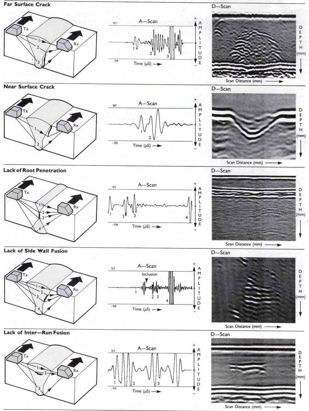
68 62

69 Annex F Additional ToFD Defect Images DEF STAN Part 5 Issue 3 (informative) Figure F.1 Remote surface breaking crack, D-scan Figure F.2 Shallow remote broken surface breaking flaw, D-scan 63

70 Figure F.3 Fatigue cracks at toe of tee-butt weld, D-scan Figure F.4 Thin plate remote surface crack, D-scan 64

71 Figure F.5 Embedded lack-of-fusion and near surface crack, D-scan Figure F.6 Intermittent HAZ crack and slag line, tee-butt weld toe, D-scan 65


72 Figure F.7 Crossing tee-butt weld and defective weld repair area, D-scan Figure F.8 Column type broken flaw at crossing tee-butt weld, D-scan 66
73 Annex G Ultrasonic Phased Array Technique DEF STAN Part 5 Issue 3 (informative) G.1 Basic Principles G.1.1 The ultrasonic phased array technique is not new; the concept of utilising multiple piezoelectric crystals within a single probe has been around for many years. Typically these early phased array probes contained a relatively small number of comparatively large crystals that resulted in a broad, paintbrush style, ultrasound beam. While these were effective as a coarse wide-area screening probe, particularly as compression wave search units checking for plate delaminations, they generally did not have the necessary resolution for the detection and sizing of welding flaws. G.1.2 Today s weld inspection ultrasonic phased array technology relies on many of the advances in medical ultrasound, electronic miniaturisation, fabrication and computer processing technology. Resulting in powerful manual and automated phased array inspection systems, that are finding greater application in industry. G.1.3 Phased array transducers now contain anything from 8 to 128 crystals or elements. The elements can be arranged in a linear, annular (circular doughnut-shaped elements) or a matrix configuration. In a linear array the width of each element can range from 0.5 mm to 2.5 mm and is generally much smaller than its length. A 32-element linear transducer with a 2.5 mm grid would therefore be at least 80 mm long. Each element within the array can act as a separate ultrasonic transducer. Although independently driven they can be pulsed in-groups was well as individually in a time sequence to produce various wavefronts. When pulsed, each element emits a small ultrasonic wave and the wavefronts from each element interfere, both destructively and constructively, generating an overall wavefront, as illustrated in Figure G.1. To ensure that the sound beam is in phase with constructive interference each active element of the transducer is pulsed at slightly different time, i.e. computer-controlled excitation of amplitude and delay of the individual elements. ELECTRONIC PULSE ELEMENTS WAVEFRONT Figure G.1 Phased Array Transducer 67
74 G.1.4 The control over which element or group of elements are to be activated and the width and time delay (measured in nanoseconds) of the high voltage triggering pulse for each element are known as Delay or Focal laws. These focal laws allow the generation of various sound beams and gives the ability to; electronically focus at different depths, electronically scan across the transducer elements, electronically steer the sound beam to different angles, and electronically sweep the sound beam over a range of angles, typically a ±30 range from a flat transducer. G.1.5 Like conventional ultrasonic transducers, the phased array transducer must act as both a transmitter and as a receiver. In transmission mode, after receiving a trigger signal the inspection system fires each element with a high-voltage pulse, width and time delay defined by the delay or focal law, creating a beam with a specific angle and focus depth. This beam interacts with the defect and is reflected back to the transducer. The transducer acting now as a receiver picks up these return signals. The inspection system then processes the returned signals in accordance with the receiving focal law (time-shifts the signals for each element) and generates a composite ultrasonic signal that is displayed and recorded. G.1.6 While it is possible to electronically steer the sound beam over a range of angles with a flat transducer, G.1.4, it is not possible to cover the range of angles used in the inspection of welds. Like conventional ultrasonic transducers the phased array transducer is therefore coupled to a wedge of material (usually acrylic) in order to achieve the spread of angles necessary for weld inspection. Again, like conventional ultrasonics this produces shear wave sound beams at a nominal angle in the material being examined in accordance with Snell's law. It has been found that the sound beam can be effectively swept over a ±15 angular range about this nominal probe angle, e.g. a swept range of 40 to 70 in shear would have a nominal angle of about 55 in shear. Which covers the three-principle inspection angles, 45, 60 and 70 within one probe. G.2 Beam Scanning Techniques There are three main beam scanning techniques, which are illustrated in Figure G.2 and described below. a) Dynamic Depth Focusing: Scanning along the beam axis is performed at different focal depths. Typically a single transmitted pulse is used and the focus point is moved along the line of the nominal beam axis by varying the focal law. For dynamic depth focusing, the focal law takes the form of a parabola with the delay increasing from the edges of the array towards the centre. The delay on the central element will double as the focal distance is halved. This technique is an alternative to using several transducers to focus at different depths. b) Electronic Scanning: Electronic or linear scanning involves energising a smaller sub-set of the phased array elements to form the desired beam profile and then electronically multiplexing this focal law along the aperture (length) of the array. When angled wedges are used, the focal law has to be modified to take into account the different time delays within the wedge for each element. This is the electronic equivalent to mechanically raster scanning a probe of a smaller aperture across the length of the larger phased array probe. This can be combined with dynamic depth focusing and electronic steering to sweep a focused, angled or a focused and angled beam across the length of the probe. c) Electronic Steering: In electronic steering or sectorial scanning (also called azimuthal or angular scanning) different delays are applied to individual elements to steer the sound beam to a fixed angle or to sweep the sound beam over a range of angles. When angled wedges are used the focal law has a parabolic shape for the given angle calculated from Snell's law. To obtain angles lower than the Snell's law value, the parabolic shape is modified by increasing the pulse delay on the elements from the back toward the front of the probe. To obtain angles greater than the Snell's law value the pulse delay is higher for the elements at the back of the probe, as the sound from the front elements have a longer path in the wedge material and must be excited first. 68

75 DELAY/FOCAL LAW ELECTRONIC SCANNING DELAY/FOCAL LAW DYNAMIC DEPTH FOCUSING BEAM MOVEMENT ELECTRONIC STEERING Figure G.2 Beam Scanning Techniques G.3 Beam Coverage G.3.1 To ensure that the inspection set-up is appropriate and that either full coverage or at least coverage of the weld region of interest is achieved, it is important to generate coverage diagrams, beam plots, prior to the examination. These coverage diagrams, examples are given in Figure G.3 and Figure G.4, model the beam angle and scanning (linear or sectorial/azimuthal) and defines the index point in accordance with the focal law applied. The model defines the stand-off required to achieve the desired coverage and the final probe position if raster scanning is also required. Figure G.3 Linear Scan Coverage Diagram 69

76 Figure G.4 Sectorial or Azimuthal Scan Coverage Diagram NOTE For clarity the two coverage diagrams do not include raster scan lines, which would be required if full weld coverage was needed. G.4 Phased Array Imaging Phased array scanning of welds is usually performed with a mechanical scanning rig which can be either motor or manually driven over the material under examination. In both cases positional feedback from an encoder must be provided to the controlling computer to allow data collection. The data collected can then be displayed in a variety of views or any combination of views for interpretation. Electronic B-scan, displays data from the multiple A-scans generated from a linear scan. Sectorial scan or S-scan, displays the data from a sectorial or azimuthal scan. The S-scan display has been adapted from medical ultrasound to fit industrial inspection applications. Positional B-scan, displays the data from the electronic B-scans or S-scans along with probe movement (raster position) to generate a linear B-scan image. Positional C-scan, displays a composite image from the multiple A-scans generated from either a linear or sectorial scan and from raster movement along with probe movement along the weld. Positional D-scan, displays a composite image from the multiple A-scans generated from either a linear or sectorial scan along with probe movement along the weld. 70

 S-scan Figure G.")
77 G.4.1 Examples of various display types from actual weld examinations are given in Figures G.5 to G.7. Figure G.5 Sectorial (azimuthal) S-scan Figure G.6 Linear Electronic Angled Beam Scan 71

78 Echo-dynamic B-scan C-scan D-scan A-scan Figure G.7 Combined, A-scan, Electronic B-scan, C-scan, D-scan, and Echo-dynamic views G.5 Optimising Phased Array Techniques G.5.1 The number and size of elements within a phased array transducer is a factor which may affect the inspection accuracy. Increasing the number of elements improves the signal to noise ratio. This however may limit the ability to perform an effective linear scan of the elements. The calculation of the start and finish stand-off positions and the production of coverage diagrams is essential for linear scans, particularly for thick section welds, to ensure full coverage of the weld or the region of interest. G.5.2 The probe wedges used for phased array transducers are typically general purpose wedges with little design considerations for standing echoes or sound reverberations within the wedges. It is important that details of standing echoes and probe reverberations are understood and identified as such. It is possible that for a given array spacing, wedge angle and focal law, diffraction grating side lobes may be produced. The effect of these diffraction grating lobes is to be minimised. For specific applications specially designed probes and wedges will be beneficial and where the same phased array scanning techniques are in routine used then wedge design is recommended. G.5.3 As yet there are no specific national standards for phased array transducers or inspection procedures. The application of phased array techniques should therefore be supported with a technical procedure sheet that details the probe geometry, wedge design, focal laws, calibration, sensitivity etc. Assessment of the probe and wedge performance should be made with reference to BS EN part 2 as a starting point. Establishing the sensitivity of the phased array techniques is much more complex than for conventional ultrasonic techniques, as the sensitivity will vary for each focal law applied and for each mode of scanning. One approach is to select the optimum sensitivity setting that provides detectability of the defects within a given test-piece geometry and material, e.g. the defect image is visible against the background noise, probe or geometry echoes. To achieve this it is usual to set the sensitivity at 80% full screen height for a particular target, e.g. a 3 mm diameter side drilled hole, in a test-block at the desired region of interest. In this way the sensitivity can be compared with that from a conventional ultrasonic set-up with conventional probes. 72
79 Annex H Characterisation of Phased Array Generated Ultrasound Beams (normative) H.1 Characterisation of Ultrasound Beams H.1.1 A method for the rapid and reproducible characterisation of the ultrasound beams generated by phased array transducer/wedge combinations in terms of the generated sound beam angle or angles and the index point is outlined. This utilises the response from a specific target, 3 mm diameter side drilled hole (SDH), in a calibration block to determine the true beam angle and corresponding probe/wedge index point for the applied focal law. The calibration block should be machined from the same or ultrasonically similar material to that under examination and should contain a number of target SDH's. Details of a suggested calibration block are given in Figure H.1. The length of the block should be five times the length of the probe, it should be 60 mm or twice the weld/plate thickness under examination deep and it should be at least 50 mm thick. 20mm 10% PROBE MOVEMENT MEASURED BY ENCODER 15% REFERENCE POINT 40% 30mm 30mm GENERATED ULTRASOUND BEAM 50% 100% ALL SIDED DRILLED HOLES (SDH) ARE ø3mm 60mm MIN. 2T MAX. 100% 10% 15% 30mm 2.5 x PROBE LENGTH 2.5 x PROBE LENGTH Figure H.1 Phased Array Calibration Block H.1.2 With the probe movement encoder calibrated in accordance with the prescribed instructions for the equipment in use, a line scan across the calibration block is performed as indicated in Figure H.1. The response from the principle target, the 3 mm diameter SDH at 30 mm down and 30 mm from the block's centre-line, is displayed and assessed to give the beam characteristics. The beam angle can be determined from the depth of the indication while the index point is determined from the horizontal location of the indication. Values of acceptable tolerances for various beam angles and probe frequencies are given in Table 7. H.1.3 Examples of scans performed with a 32 element probe generating a 45 beam, from a focal law applied to a 12 element group (21 focal laws in total), from the 1 st (elements 1 to 12) and the 21 st (elements 21 to 32) focal laws are given in Figure H.2. In each case the maximum response, indicated by the intensity of the red spot, lies within the allowable tolerance a 3 mm diameter SDH at 30 mm depth with a 5 MHz 45 beam angle. 73
 Index point tolerance mm Frequency 2 MHz >2 MHz 2 MHz >2 MHz 2 MHz >2 MHZ 30 ±3 ±2")
80 Table H.1 Phased Array Beam Tolerance Values Beam angle Beam angle tolerance degree Hole depth tolerance (% of hole depth) Index point tolerance mm Frequency 2 MHz >2 MHz 2 MHz >2 MHz 2 MHz >2 MHZ 30 ±3 ±2 ±3% ±2% ±1 or 2 ±1 45 ±3 ±2 ±5% ±3% ±1 or 2 ±1 60 ±3 ±2 ±8% ±6% ±1 or 2 ±1 70 ±3 ±2 ±17% ±11% ±1 or 2 ±1 1 st Focal law group 21 st Focal law group Figure H.2 Focal Law Images H.1.4 The probe/wedge performance can then be checked over the desired beam path by scanning towards one of the groups of three SDH's near the edges of the block. H.2 Coverage Diagrams H.2.1 This block can also be used to confirm or develop coverage diagrams for the scans that are going to be used in the examination. Having characterised the beam and confirmed that the focal laws are generating beams of the desired angle and scan type, linear or sectorial. The probe is positioned on the calibration block so that the response from the target is maximised for the 1 st focal law, e.g. first beam in a linear scan or lowest angle in a sectorial scan. The position of the index point is recorded along with the distance to the target. The probe is then repositioned to maximise the response from the last focal law, e.g. the final linear beam or highest sectorial angle and the position of the index point and distance to the target is recorded. From the measurements the beam coverage can be confirmed and a coverage diagram generated. 74
New Highly Productive Phased Array Ultrasonic Testing Machine for Aluminium Plates for Aircraft Applications
 19 th World Conference on Non-Destructive Testing 2016 New Highly Productive Phased Array Ultrasonic Testing Machine for Aluminium Plates for Aircraft Applications Christoph HENKEL 1, Markus SPERL 1, Walter
UNIFIED FACILITIES GUIDE SPECIFICATIONS
 USACE / NAVFAC / AFCEC / NASA UFGS-41 36 30.00 10 (January 2008) ---------------------------------- Preparing Activity: USACE Superseding UFGS-41 36 30.00 10 (April 2006) UNIFIED FACILITIES GUIDE SPECIFICATIONS
Inspection of CANDU Reactor Pressure Tubes Using Ultrasonics
 17th World Conference on Nondestructive Testing, 25-28 Oct 2008, Shanghai, China Inspection of CANDU Reactor Pressure Tubes Using Ultrasonics Michael TRELINSKI Inspection & Maintenance Services Ontario
In-Service Inspection of Ammonia Storage Tanks
 White Paper In-Service Inspection of Ammonia Storage Tanks By: Ole Noerrekaer Mortensen, Business Manager, Advanced NDT Global at FORCE Technology Personnel ready for mounting the Inspection System in
STANDARD SPECIFICATION FOR SPLIT TEES (HOT TAP MATERIAL)
") STANDARD SPECIFICATION FOR SPLIT TEES (HOT TAP MATERIAL) TEE (HOT TAPPING MATERIAL) S-04-02-040 Page 1 of 7 1.0 SCOPE This specification covers the basic requirements for the design, manufacture and supply
STANDARD SPECIFICATION FOR SPLIT TEES (HOT TAP MATERIAL) TEE (HOT TAPPING MATERIAL) S-04-02-040 Page 1 of 7 1.0 SCOPE This specification covers the basic requirements for the design, manufacture and supply
Pressure Equipment Directive PED 2014/68/EU Commission's Working Group "Pressure"
 F. INTERPRETATION OF THE ESSENTIAL SAFETY REQUIREMENTS ON MANUFACTURING Guideline F-01 Guideline related to: Annex 1 Section 3.1.2 According to section 3.1.2 (permanent joining) of Annex I, the third party
Standard Practice for Ultrasonic Contact Examination of Weldments 1
 Designation: E 164 03 Standard Practice for Ultrasonic Contact Examination of Weldments 1 This standard is issued under the fixed designation E 164; the number immediately following the designation indicates
Contents. 1. Non Destructive Testing Requirements. 2. Non Destructive Testing Methods Magnetic Particle Examination
 1 Contents 1. Non Destructive Testing Requirements 2. Non Destructive Testing Methods Magnetic Particle Examination 3. Non Destructive Testing Methods Dye Penetrant Examination 4. Non Destructive Testing
Accreditation for In-Service Inspection of Transportable Pressure Receptacles (TPRs)
") RG 3 Edition 4 December 2018 Accreditation for In-Service Inspection of Transportable Pressure Receptacles (TPRs) RG 3 / Edition: 4 Page 1 of 8 Contents 1. Introduction 2 2. Scope - Inspection Services
RG 3 Edition 4 December 2018 Accreditation for In-Service Inspection of Transportable Pressure Receptacles (TPRs) RG 3 / Edition: 4 Page 1 of 8 Contents 1. Introduction 2 2. Scope - Inspection Services
This document is a preview generated by EVS
 INTERNATIONAL STANDARD ISO 16148 Second edition 2016-04-15 Gas cylinders Refillable seamless steel gas cylinders and tubes Acoustic emission examination (AT) and follow-up ultrasonic examination (UT) for
The Use of Ultrasonic Inspections at Elevated Temperature
 18th World Conference on Nondestructive Testing, 16-20 April 2012, Durban, South Africa The Use of Ultrasonic Inspections at Elevated Temperature Alex McLAY, Jan VERKOOIJEN, TÜV Rheinland Sonovation 4906AZ
Employer s Unit of Competence Magnetic particle testing of materials, products and plant
 Employer s Unit of Competence Magnetic particle testing of materials, products and plant Image - if cover page required Supported by lead employer Overview This unit identifies the competencies required
APPENDIX 1. PART 10: Leak Detection Inspector, Level 1, 2 and 3 CERTIFICATION SCHEME FOR PERSONNEL. 3 rd Edition, February 2016
 CERTIFICATION SCHEME FOR PERSONNEL Document No. CSWIP-ISO-NDT-11/93-R Requirements for the Certification of Personnel Engaged in Non- Destructive Testing in accordance with the requirements of BS EN ISO
Guided Wave Testing (GWT)
") Guided Wave Testing (GWT) Use of guided wave testing for the detection and monitoring of corrosion under insulation Peter Philipp Independent GWT consultant Level 3 GUL Level 3 PCN GWT BINDT-ICorr. - 12/05/2013
Guided Wave Testing (GWT) Use of guided wave testing for the detection and monitoring of corrosion under insulation Peter Philipp Independent GWT consultant Level 3 GUL Level 3 PCN GWT BINDT-ICorr. - 12/05/2013
MANUFACTURING PROCEDURE SPECIFICATION INSPECTION TEST PLAN
 TEST PLAN 1.0 SCOPE The purpose of this work instruction is to establish and maintain documented procedure to ensure that the magnetic particle inspection of bend body over extrados and intrados is carried
RECENT IMPROVEMENTS REGARDING ULTRASONIC CRACK INSPECTION OF PIPELINES Herbert Willems, Thomas Hennig NDT Global, Stutensee, Germany
 RECENT IMPROVEMENTS REGARDING ULTRASONIC CRACK INSPECTION OF PIPELINES Herbert Willems, Thomas Hennig NDT Global, Stutensee, Germany ABSTRACT Crack inspection of pipelines using conventional ultrasonic
Standard Practice for Eddy-Current Examination of Steel Tubular Products Using Magnetic Saturation 1
 Designation: E 309 95 An American National Standard Standard Practice for Eddy-Current Examination of Steel Tubular Products Using Magnetic Saturation 1 This standard is issued under the fixed designation
Air Diving Inspection of ABC Mock-Up Caisson Project 123
 Air Diving Inspection of ABC Caisson Project 123 Client: CLIENT Facility: CDE, Norway Item Inspected: ABC Caisson Inspection Method: Manual Surface Eddy Current Date Commenced: 04 November 2013 Date of
RULES FOR CLASSIFICATION Naval vessels. Part 1 Classification and surveys Chapter 5 Surveys for submarines. Edition January 2016 DNV GL AS
 RULES FOR CLASSIFICATION Naval vessels Edition January 2016 Part 1 Classification and surveys Chapter 5 The content of this service document is the subject of intellectual property rights reserved by ("DNV
BRITISH STANDARD BS 341-4: Transportable gas container valves. Part 4: Pressure relief devices ICS
 BRITISH STANDARD BS 341-4:2004 Transportable gas container valves Part 4: Pressure relief devices ICS 23.060.40 This British Standard, having been prepared under the direction of the Standards Policy and
AEROSPACE MATERIAL SPECIFICATION
 400 Commonwealth Drive, Warrendale, PA 15096-0001 AEROSPACE MATERIAL SPECIFICATION Submitted for recognition as an American National Standard AMS 2630B Issued JUN 1960 Revised MAR 1995 Superseding AMS
Title: Standard Operating Procedure for R&R Environmental Devices Model MFC201 Gas Dilution Calibrator
 Procedure No: SOP-029 Revision No: 1.1 (December 29, 2010) Page No.: 1 of 7 1. INTRODUCTION AND SCOPE To obtain timely data for the purpose of air quality assessment, air quality trend reporting, air quality
EXPERIMENTAL RESULTS OF GUIDED WAVE TRAVEL TIME TOMOGRAPHY
 18 th World Conference on Non destructive Testing, 16-20 April 2012, Durban, South Africa EXPERIMENTAL RESULTS OF GUIDED WAVE TRAVEL TIME TOMOGRAPHY Arno VOLKER 1 and Hendrik VOS 1 TNO, Stieltjesweg 1,
ISO INTERNATIONAL STANDARD. Hydraulic fluid power Filter elements Determination of resistance to flow fatigue using high viscosity fluid
 INTERNATIONAL STANDARD ISO 23181 First edition 2007-08-15 Hydraulic fluid power Filter elements Determination of resistance to flow fatigue using high viscosity fluid Transmissions hydrauliques Éléments
INSPECTION OF RECOVERY BOILERS
 INSPECTION OF RECOVERY BOILERS W. B. A. (Sandy) Sharp SharpConsultant, Columbia, Maryland, U.S.A. TAPPI Kraft Recovery Short Course St. Petersburg, Florida, January 7-10, 2008 OUTLINE Purpose of inspections
Other Si min/max. Cr min/max. 0.4/ / / / Bal.
 178.46 Specification 3AL seamless aluminum cylinders. (a) Size and service pressure. A DOT 3AL cylinder is a seamless aluminum cylinder with a imum water capacity of 1000 pounds and minimum service pressure
SEMFWE305 HY20 04 Welding materials by the Semi-Automatic MIG/MAG and Flux Cored Arc processes
 SEMFWE305 HY20 04 Welding materials by the Semi-Automatic MIG/MAG and Flux Cored Overview This standard identifies the competencies you need to prepare and operate semi-automatic MIG, MAG and flux cored
Standard Operating Procedure Measuring & Testing Equipment
 Standard Operating Procedure Measuring & Testing Equipment Purpose: 7.6 Responsibility: 7.6d Scope To have a procedure to ensure that all is controlled, maintained and calibrated to ensure that Product
TECHNICAL REPORT ON CAPACITY BUILDING IN USE OF EDDY CURRENT TESTING EQUIPMENT
 REFERENCE NO. PNRA-CNS-NDT-49-13 MAY, 2013 TECHNICAL REPORT ON CAPACITY BUILDING IN USE OF EDDY CURRENT TESTING EQUIPMENT PAKISTAN NUCLEAR REGULATORY AUTHORITY P.O. BOX 1912, ISLAMABAD i Intentionally
EFFECTIVE & RELIABLE INSPECTION OF FIN-FAN COOLER TUBES
 7 th MENDT Conference Bahrain - 2015 EFFECTIVE & RELIABLE INSPECTION OF FIN-FAN COOLER TUBES ANDREAS BOENISCH & ABDUL RAHMAN TAQATEQ CONTENT - Short overview Fin Fan Cooler & Tube Types, Tube corrosion
P-04 Stainless Steel Corrugated Hoses and Metal Bellows Expansion Joints
 Guideline No.P-04 (201510) P-04 Stainless Steel Corrugated Hoses and Metal Bellows Expansion Joints Issued date: 20 th October 2015 China Classification Society Foreword This Guideline is a part of CCS
Status Date Prepared Reviewed Endorsed Approved
 Discipline Engineering Standard NSW Category Signalling Title Rerailing Precautions to be Taken Reference Number SMP 26 (RIC Standard: SC 00 52 00 26 SI) Document Control Status Date Prepared Reviewed
Accreditation for In-Service Inspection of Pressure Systems/Equipment
 RG 2 Edition 5 November 2018 - Draft for consultation Accreditation for In-Service Inspection of Pressure Systems/Equipment RG 2 / Edition: 5 Page 1 of 10 Contents 1. Introduction 2 2. Scope - Inspection
Combined NDT advanced techniques as an alternative to radiography for NDT of primary component circumferential welds. Ready for industrialization.
 Combined NDT advanced techniques as an alternative to radiography for NDT of primary component circumferential welds. Ready for industrialization. More info about this article: http://www.ndt.net/?id=22514
Survey of Underwater NDT Technologies for Offshore Assets
 Survey of Underwater NDT Technologies for Offshore Assets Ayman Amer, Fadl Abdellatif, Ali Outa, Hassane Trigui, Sahejad Patel, Ameen Obedan, Fernando Diaz Ledezma, Hamad Al Saiari and Ihsan Taie, Saudi
Ultrasonic Inspection of In-Service Composite Bicycles and Components
 Ultrasonic Inspection of In-Service Composite Bicycles and Components Cyclitech 6-7 Dec 2016 Raoul Luescher Director Luescher Teknik Pty Ltd Personal Background Diploma of Mech Eng 1989. Level 2 NDI technician
TG GUIDELINES CONCERNING CALIBRATION INTERVALS AND RECALIBRATION
 GUIDELINES CONCERNING CALIBRATION INTERVALS AND RECALIBRATION Approved By: Senior Manager: Mpho Phaloane Revised By: Field Manager: Neville Tayler Date of Approval: 2015-08-26 Date of Implementation: 2015-08-26
Cutting and shaping materials using thermal cutting equipment
 Unit 824 Cutting and shaping materials using thermal cutting equipment UAN: H/600/5883 Level: Level 2 Credit value: 14 GLH: 64 Relationship to NOS: This unit has been derived from national occupational
GB/T Translated English of Chinese Standard: GB/T NATIONAL STANDARD OF THE
 Translated English of Chinese Standard: GB/T8361-2001 www.chinesestandard.net Sales@ChineseStandard.net GB NATIONAL STANDARD OF THE PEOPLE S REPUBLIC OF CHINA GB/T 8361-2001 Replacing GB/T 8361-1987 The
Ultrasonic testing procedures for volumetric and surface inspection of CANDU pressure tubes
 IV Conferencia Panamericana de END Buenos Aires Octubre 2007 Ultrasonic testing procedures for volumetric and surface inspection of CANDU pressure tubes Michael Trelinski Senior Technical Expert UT Fuel
JAPANESE PD EXAMINATIONS FOR DEPTH SIZING OF SCC IN AUSTENITIC STAINLESS STEEL PIPES FROM 2006 TO 2012
 JAPANESE PD EXAMINATIONS FOR DEPTH SIZING OF SCC IN AUSTENITIC STAINLESS STEEL PIPES FROM 2006 TO 2012 Keiji Watanabe, Hajime Shohji, and Koichiro Hide PD center, Central Research Institute of Electric
AEROSPACE MATERIAL SPECIFICATION
 400 Commonwealth Drive, Warrendale, PA 15096-0001 AEROSPACE MATERIAL SPECIFICATION AMS 2632A Issued MAR 1974 Revised MAR 1995 Superseding AMS 2632 Inspection, Ultrasonic, of Thin Materials 0.50 Inch (12.7
A comparison of the Magnetic Flux Leakage and Ultrasonic methods in the detection and measurement of corrosion pitting in ferrous plate and pipe.
 A comparison of the Magnetic Flux Leakage and Ultrasonic methods in the detection and measurement of corrosion pitting in ferrous plate and pipe. J. C. Drury I.Eng. M.Inst.NDT Silver Wing (UK) Limited
INSPECTION, TESTING AND CERTIFICATION OF GASFITTING WORK DONE UNDER SUPERVISION
 ISSN 1172-3416 NZ GCP 1 : 1993 NEW ZEALAND GAS CODE OF PRACTICE for INSPECTION, TESTING AND CERTIFICATION OF GASFITTING WORK DONE UNDER SUPERVISION Issued by the Secretary of Commerce in accordance with
GUIDELINES. Systems. Pressure. Guidelines Acceptance of equipment, establishment of safe operating limits and fitness for service
 GUIDELINES Pressure Systems Guidelines Acceptance of equipment, establishment of safe operating limits and fitness for service Document Reference: PSG 16 Issue 04 Dated 13/09/16 The Safety Assessment Federation
MSC Guidelines for Pressure Vessels
 References: a. 46 CFR Part 54 Pressure Vessels S. T. Brady, CDR, Chief, Engineering Division b. ASME Boiler and Pressure Vessel Code (BPVC), Section VIII, Division 1, (1998 Edition) c. Navigation and Inspection
Testing Procedures of Watertight Compartments
 (1996) (Rev.1 Feb 2001) (Rev.2 May 2001) (Rev.3 May 2010) (Rev.4 Aug 2012) Testing Procedures of Watertight Compartments.1 Application Revision 4 of this UR is to be complied with in respect of the testing
Liquefied gas cargo tanks and process pressure vessels
 .1 -.3 Liquefied gas cargo tanks and process pressure vessels.1 General.1.1 The present texts give the general principles which are applied by Classification Societies for approval and survey of the relevant
IAPMO GUIDE CRITERIA FOR BALL VALVES IAPMO IGC PURPOSE
 INTERNATIONAL ASSOCIATION OF PLUMBING AND MECHANICAL OFFICIALS IAPMO GUIDE CRITERIA FOR BALL VALVES IAPMO IGC 157-20067 1 PURPOSE 1.1 The purpose of this standard is to establish an acceptable standard
Non-Destructive Testing of Rail (for Internal & Surface Defects)
") Division / Business Unit: Function: Document Type: Enterprise Services Track & Civil Standard Non-Destructive Testing of Rail (for Internal & Surface Defects) Applicability ARTC Network Wide SMS Publication
Division / Business Unit: Function: Document Type: Enterprise Services Track & Civil Standard Non-Destructive Testing of Rail (for Internal & Surface Defects) Applicability ARTC Network Wide SMS Publication
SPECIFICATION FOR INSTALLATION OF RAISED PAVEMENT MARKERS. This specification shall apply to the installation of raised pavement markers.
 SPECIFICATION FOR INSTALLATION OF RAISED PAVEMENT MARKERS 1 SCOPE This specification shall apply to the installation of raised pavement markers. 2 DEFINITIONS Type A Marker - Retroreflective raised pavement
INTERNATIONAL STANDARD
 INTERNATIONAL STANDARD ISO 10464 First edition 2004-08-15 Gas cylinders Refillable welded steel cylinders for liquefied petroleum gas (LPG) Periodic inspection and testing Bouteilles à gaz Bouteilles rechargeables
SEMMME3-073 Checking that completed assemblies comply with specification
 Checking that completed assemblies comply with specification Overview This unit identifies the competences you need to carry out checks on mechanical assemblies, in accordance with approved procedures.
Standard Recommended Practice. Field Measurement of Surface Profile of Abrasive Blast-Cleaned Steel Surfaces Using a Replica Tape
 NACE Standard RP0287-2002 Item No. 21035 Standard Recommended Practice Field Measurement of Surface Profile of Abrasive Blast-Cleaned Steel Surfaces Using a Replica Tape This NACE International standard
Moor, Tend Mooring And Unmoor Ship - Supervisor Level -
 Marine Terminal Operations Competency Standard Moor, Tend Mooring And Unmoor Ship - Supervisor Level - Industry : Oil, Chemical and Gas Industry Competency Category : 2.0 Moor, tend mooring and unmoor
ISO INTERNATIONAL STANDARD. Steel wire ropes for the petroleum and natural gas industries Minimum requirements and terms of acceptance
 INTERNATIONAL STANDARD ISO 10425 First edition 2003-08-15 Steel wire ropes for the petroleum and natural gas industries Minimum requirements and terms of acceptance Câbles en acier pour les industries
Flexible hoses - Non-metallic materials
 CLASS PROGRAMME Type approval DNVGL-CP-0183 Edition December 2015 The electronic pdf version of this document, available free of charge from http://www.dnvgl.com, is the officially binding version. FOREWORD
1 Exam Prep. Tabs and Highlights
 1 Exam Prep NFPA 14: Standard for the Installation of Standpipe and Hose Systems Tabs and s These 1 Exam Prep tabs are based on the NFPA 14: Standard for the Installation of Standpipe and Hose Systems,
SEMFEW205 - SQA Unit Code H1VP 04 Joining materials by the manual MIG/MAG and other continuous wire processes
 Joining materials by the manual MIG/MAG and other continuous wire Overview This unit identifies the competencies you need to prepare and operate manual MIG, MAG or cored-wire arc welding equipment, in
SEMEEE36 Checking the compliance of electrical equipment against the specification
 Checking the compliance of electrical equipment against the Overview This unit identifies the competences you need to carry out compliance checks on electrical equipment, in accordance with approved procedures.
PORTS AUSTRALIA. PRINCIPLES FOR GATHERING AND PROCESSING HYDROGRAPHIC INFORMATION IN AUSTRALIAN PORTS (Version 1.5 November 2012)
") PORTS AUSTRALIA PRINCIPLES FOR GATHERING AND PROCESSING HYDROGRAPHIC INFORMATION IN AUSTRALIAN PORTS (Version 1.5 November 2012) PREFACE These Principles have been prepared by the Hydrographic Surveyors
PORTS AUSTRALIA PRINCIPLES FOR GATHERING AND PROCESSING HYDROGRAPHIC INFORMATION IN AUSTRALIAN PORTS (Version 1.5 November 2012) PREFACE These Principles have been prepared by the Hydrographic Surveyors
Standard Practice for Fabricating and Checking Aluminum Alloy Ultrasonic Standard Reference Blocks 1
 Designation: E 127 98 AMERICAN SOCIETY FOR TESTING AND MATERIALS 100 Barr Harbor Dr., West Conshohocken, PA 19428 Reprinted from the Annual Book of ASTM Standards. Copyright ASTM Standard Practice for
DIFFERENT SOLUTIONS TO INSPECT PLATFORM RISERS. By R van Agthoven and H Quakkelsteijn, ApplusRTD, Rotterdam, The Netherlands
 DIFFERENT SOLUTIONS TO INSPECT PLATFORM RISERS By R van Agthoven and H Quakkelsteijn, ApplusRTD, Rotterdam, The Netherlands SUMMARY The need for the inspection of pipelines and risers is growing, as the
1. Scope: This document describes the procedure for verifying the performance of vaccine vial monitors.
 PQS Independent type-testing protocol WHO/PQS/E06/IN05.VP.2 Original: English Distribution: General TITLE: Vaccine Vial Monitor Product verification protocol: E06/IN05.VP.2 Applies to specification ref(s):
Figure 1 - JPIF proposal for ISO standardisation of the CAI test method
 DEPC-MN 36 INTRODUCTION The use of the compression-after-impact (CAI) test method for laminated fibrereinforced plastic (FRP) materials, particularly where the critical loading mode (compression) is directly
Industry Guidelines POLYETHYLENE (PE) PIPES AND FITTINGS FOR COMPRESSED AIR ISSUE 6.8
 PIPES AND FITTINGS FOR COMPRESSED AIR ISSUE 6.8") Industry Guidelines POLYETHYLENE (PE) PIPES AND FITTINGS FOR COMPRESSED AIR ISSUE 6.8 Ref: POP002 19 APR 2009 Disclaimer In formulating this guideline PIPA has relied upon the advice of its members and,
Industry Guidelines POLYETHYLENE (PE) PIPES AND FITTINGS FOR COMPRESSED AIR ISSUE 6.8 Ref: POP002 19 APR 2009 Disclaimer In formulating this guideline PIPA has relied upon the advice of its members and,
Australian Standard. Bourdon tube pressure and vacuum gauges AS
 AS 1349 1986 Australian Standard Bourdon tube pressure and vacuum gauges [Title allocated by Defence Cataloguing Authority: GAUGES, PRESSURE AND VACUUM (Bourdon Tube Type)... NSC Gp 66] This Australian
SLOP RECEPTION AND PROCESSING FACILITIES
 RULES FOR CLASSIFICATION OF SHIPS NEWBUILDINGS SPECIAL SERVICE AND TYPE ADDITIONAL CLASS PART 5 CHAPTER 8 SLOP RECEPTION AND PROCESSING FACILITIES JANUARY 2011 CONTENTS PAGE Sec. 1 General Requirements...
Agenda Item 6-ATM Coordination (Airspace restructuring, AIS and SAR agreements)
") BOBASIO/5 IP06 31 st August-2 nd September 2015 The Fifth ATS Coordination meeting of Bay of Bengal, Arabian Sea and Indian Ocean Region (BOBASIO/5) New Delhi, India, 31 st August -2 nd September, 2015.
BOBASIO/5 IP06 31 st August-2 nd September 2015 The Fifth ATS Coordination meeting of Bay of Bengal, Arabian Sea and Indian Ocean Region (BOBASIO/5) New Delhi, India, 31 st August -2 nd September, 2015.
CLASS D - SENSITIVE LEAK TEST GAS AND BUBBLE METHOD. 1.1 To provide definitive requirements for PNEUMATIC pressure testing of piping systems.
 Page 1 of 7 CLASS D - SENSITIVE LEAK TEST GAS AND BUBBLE METHOD 1. SCOPE 1.1 To provide definitive requirements for PNEUMATIC pressure testing of piping systems. 1.2 The piping system as used herein is
Opening and closing force guidelines
 Opening and closing force guidelines This document has been complied under guidance of ASDMA membership to provide information on the requirements of Part M of the Building regulations with regards to
Guide to Documentation and Marking Part 5 Lifting Accessories, Slings
 Guide to Documentation and Marking Part 5 Lifting Accessories, Slings Document reference LEEA 059-5 version 1 dated 31.07.14 Introduction. This guide is aimed at manufacturers, distributors and users of
MAINTENANCE AND SAFETY OF CNG REFUELLING STATIONS
 ISSN 1172-3416 NZ GCP 2 : 1993 NEW ZEALAND GAS CODE OF PRACTICE for MAINTENANCE AND SAFETY OF CNG REFUELLING STATIONS Issued by the Secretary of Commerce in accordance with the Gas Act 1992 THE GAS ACT
General Accreditation Guidance. User checks and maintenance of laboratory balances
 General Accreditation Guidance User checks and maintenance of laboratory balances January 2018 Copyright National Association of Testing Authorities, Australia 2010 All intellectual property rights in
CALIBRATION SYSTEM REQUIREMENTS. ESCC Basic Specification No
 Page 1 of 8 CALIBRATION SYSTEM REQUIREMENTS ESCC Basic Specification Issue 4 February 2014 Document Custodian: European Space Agency see https://escies.org PAGE 2 LEGAL DISCLAIMER AND COPYRIGHT European
BCGA GUIDANCE NOTE 17
 BCGA GUIDANCE NOTE 17 BCGA POLICY AND GUIDANCE FOR THE SAFE FILLING OF THIRD-PARTY OWNED AND / OR MAINTAINED TANKS Revision 2: 2013 BCGA GUIDANCE NOTE 17 BCGA POLICY AND GUIDANCE FOR THE SAFE FILLING OF
Low Voltage Electricity System Safety Rules & Associated Safety Guidance
 Annex J To Loughborough University Facilities Management (FM) Health and Safety Policy Low Voltage Electricity System Safety Rules & Associated Safety Guidance 1. Introduction a. These Safety Rules are
Installing, Repairing or Modifying Construction Resources by Heating, Welding, Brazing, Soldering and Thermal Cutting in the Workplace L/505/0144
 Unit Title Ofqual unit reference number (code) Organisation Reference QCF 665 Unit Level Unit Sub Level Installing, Repairing or Modifying Construction Resources by Heating, Welding, Brazing, Soldering
MIL-STD-883H METHOD EXTERNAL VISUAL
 * EXTERNAL VISUAL 1. PURPOSE. The purpose of this test method is to verify the workmanship of hermetically packaged devices. This test method shall also be utilized to inspect for damage due to handling,
TECHNICAL SPECIFICATION
 TECHNICAL SPECIFICATION IEC TS 61245 Edition 2.0 2015-03 Artificial pollution tests on high-voltage ceramic and glass insulators to be used on d.c. systems INTERNATIONAL ELECTROTECHNICAL COMMISSION ICS
Vibrating Wire Load Cell (3, 4, 5 And 6 Gauge Cells) User Manual
 User Manual") Vibrating Wire Load Cell (3, 4, 5 And 6 Gauge Cells) User Manual Man 188 1.1.0 06/08/2014 Chris Rasmussen Philip Day Chris Rasmussen Manual No. Revision Date Originator Checked Authorised for Issue User
Vibrating Wire Load Cell (3, 4, 5 And 6 Gauge Cells) User Manual Man 188 1.1.0 06/08/2014 Chris Rasmussen Philip Day Chris Rasmussen Manual No. Revision Date Originator Checked Authorised for Issue User
National Standard for Commercial Vessels
 National Standard for Commercial Vessels Part E Operations Published 17 May 2013 Endorsed by the Standing Council on Transport and Infrastructure 10 May 2013 Commonwealth of Australia This work is copyright.
Status Date Prepared Reviewed Endorsed Approved
 Discipline Engineering Standard NSW Category Signalling Title Introduction to Signalling Maintenance Procedures Reference Number SMP 01 (RIC Standard: SC 00 52 00 01 SI) Document Control Status Date Prepared
ICE LOADS MONITORING SYSTEMS
 Guide for Ice Loads Monitoring Systems GUIDE FOR ICE LOADS MONITORING SYSTEMS MAY 2011 American Bureau of Shipping Incorporated by Act of Legislature of the State of New York 1862 Copyright 2011 American
14/10/2013' Bathymetric Survey. egm502 seafloor mapping
 egm502 seafloor mapping lecture 10 single-beam echo-sounders Bathymetric Survey Bathymetry is the measurement of water depths - bathymetry is the underwater equivalent of terrestrial topography. A transect
CORESTA RECOMMENDED METHOD N 6
 CORESTA RECOMMENDED METHOD N 6 DETERMINATION OF VENTILATION DEFINITIONS AND MEASUREMENT PRINCIPLES (2015 Revision September 2016) 1. SCOPE This CORESTA Recommended Method specifies a method for the determination
Performance Standards for Non-Turf Cricket Pitches Intended for Outdoor Use [TS6] ecb.co.uk
![Performance Standards for Non-Turf Cricket Pitches Intended for Outdoor Use [TS6] ecb.co.uk](/thumbs/74/69661289.jpg "Performance Standards for Non-Turf Cricket Pitches Intended for Outdoor Use [TS6] ecb.co.uk") Performance Standards for Non-Turf Cricket Pitches Intended for Outdoor Use [TS6] ecb.co.uk 01 Introduction and Scope This Standard describes the requirements for non-turf cricket pitch systems intended
Performance Standards for Non-Turf Cricket Pitches Intended for Outdoor Use [TS6] ecb.co.uk 01 Introduction and Scope This Standard describes the requirements for non-turf cricket pitch systems intended
Outline for Safety Performance Supervisory Inspection of Boiler and Pressure Vessel Products
 Outline for Safety Performance Supervisory Inspection of Boiler and Pressure Vessel Products Appendix 1 Supervisory Inspection Rule for Safety Performance of Boiler and Pressure Vessel Products Published
TECH TIPS: ROPE DEFECTS
 Hoist Ropes: Why must they be inspected? A hoist rope is not made to last forever. This is a useful fact, as the kinds of wear that appear on a rope can indicate areas of problems within an installation
R1 Maule Aerospace Technology, Inc.: Amendment ; Docket No. FAA ; Directorate Identifier 98-CE-01-AD.
 98-15-18 R1 Maule Aerospace Technology, Inc.: Amendment 39-17690; Docket No. FAA-2013-0725; Directorate Identifier 98-CE-01-AD. (a) Effective. Date This AD is effective January 21, 2014. (b) Affected ADs
E2K-L. Liquid Level Sensor That Is Unaffected by the Color of the Pipe or Liquid. Liquid Level Sensor. Ordering Information
 Liquid Level EK-L CSM_EK-L_DS_E 3 Liquid Level That Is Unaffected by the Color of the or Liquid Mount to bypass pipes. Fit a wide range of pipe diameters: 8 to mm or to mm Built-in Amplifiers to save space.
MIL-STD-883G METHOD
 STEADY-STATE LIFE 1. PURPOSE. The steady-state life test is performed for the purpose of demonstrating the quality or reliability of devices subjected to the specified conditions over an extended time
Use of Underwater Dry Welding for In Situ Repair to Offshore Structures. Sabine Powell 02/12/2016
 Use of Underwater Dry Welding for In Situ Repair to Offshore Structures Sabine Powell engineering@neptunems.com 02/12/2016 In Situ Welding Steel Structures Suitability of Repair Methods Mobile Offshore
Specifications for Synchronized Sensor Pipe Condition Assessment (AS PROVIDED BY REDZONE ROBOTICS)
") Specifications for Synchronized Sensor Pipe Condition Assessment (AS PROVIDED BY REDZONE ROBOTICS) A. Scope of Work The work covered by these specifications consists of furnishing all materials, labor,
Specifications for Synchronized Sensor Pipe Condition Assessment (AS PROVIDED BY REDZONE ROBOTICS) A. Scope of Work The work covered by these specifications consists of furnishing all materials, labor,
ASME and PED Requirements for Drum Level Instrumentation. Presented by: Amir Hedayatnia Clark-Reliance Corp.
 ASME and PED Requirements for Drum Level Instrumentation 2017 Presented by: Amir Hedayatnia Clark-Reliance Corp. Topics Gage Glasses and Remote Reading Instruments ASME Code Section I Requirements for
OPENINGS AND REINFORCEMENTS 26
 ASME BPVC.VIII.1-2015 UG-35.2 UG-36 (4) It is recognized that it is impractical to write requirements to cover the multiplicity of devices used for quick access, or to prevent negligent operation or the
DNVGL-CP-0187 Edition March 2016
 CLASS PROGRAMME Type approval DNVGL-CP-0187 Edition March 2016 The electronic pdf version of this document, available free of charge from http://www.dnvgl.com, is the officially binding version. FOREWORD
INSPECTORATE FOR DIVING EQUIPMENT SERVICING & TESTING CODE OF PRACTICE CP11:2011
 D003 INSPECTORATE FOR DIVING EQUIPMENT SERVICING & TESTING CODE OF PRACTICE CP11:2011 For INSPECTING and TESTING Transportable Pressure Receptacles (Cylinders) for Breathing Gases manufactured from Steel
Acoustic Pulse Reflectometry Brings an End to Tube Inspection Sampling By Dr. Noam Amir, Chief Technology Officer, AcousticEye
 SINCE2011 Singapore International NDT Conference & Exhibition, 3-4 November 2011 Acoustic Pulse Reflectometry Brings an End to Tube Inspection Sampling By Dr. Noam Amir, Chief Technology Officer, AcousticEye
PASSENGER SHIPS Guidelines for preparation of Hull Structural Surveys
 (Feb 2010) PASSENGER SHIPS Guidelines for preparation of Hull Structural Surveys Contents 1 Introduction 2 Preparations for Survey 2.1 General 2.2 Conditions for survey 2.3 Access to structures 2.4 Survey