How to make my Air Glide S work properly
|
|
|
- Aleesha Mills
- 6 years ago
- Views:
Transcription
1 How to make my Air Glide S work properly Originally written by Horst Rupp. Many thanks to Richard Frawley who edited and retranslated this article into proper English. 2014/11/21. The basic prerequisite for the Air Glide S, in particular the AHRS part, to work properly so that the extraneous noise (gusts, wind shifts, perturbations etc) can be removed is to ensure that it is set up correctly. The instrument is very sensitive and the installation needs to be done in a way that ensures that only the correct inputs are being sensed. Most legacy instrument installations take all pressures from probes at the rudder fin. And most unfortunately, many of them use the total energy (TE) pressure from the fin to feed in parallel a mass-measurement variometer with a capacity flask (in Germany mostly a Winter) and a pressure sensor probe variometer such as the Air Glide S (no capacity flask). There are many publications indicating the deterioration (mostly damping) of the pressure sensor probe measurements by the stream of air mass in and out of the capacity flask. So, it is obviously a somewhat bad idea to do that to your Air Glide S. This interference with a mass measuring instruments is certainly not compliant with the above mentioned basic prerequisite. Fortunately, the Air Glide S can be compensated by total pressure (called electronic compensation as opposed to TE compensation). This is a new feature of the Air Glide S arriving with V 1.1. Total pressure and TE pressure carry more or less (depends on quality of probe) the same information - but for the sign : Total pressure is static pressure PLUS pitot pressure, TE pressure is static pressure MINUS pitot pressure (probe compensation factor (~)-1). Thus, for a modern flight computer like in the Air Glide S it is no problem to derive the compensation signal from total pressure (electronic compensation). The advantage of electronic compensation is twofold: It makes the tubing so much simpler and it gets rid of the above mentioned deterioration. You may reserve the existing TE compensation pressure for the mass measuring variometer, as in legacy installations, but there is no need for a TE compensation pressure connection necessary at the Air Glide S. If you go that avenue, you will end up with a free inlet at the Air Glide S sensor box. This inlet should then be connected to static pressure (in parallel to the dedicated static pressure inlet. In the Air Glide S setup there is a setting to tell the instrument it should use the electronic compensation method. The appropriate value in the Air Glide S setup has to be set to 100% (see details below).
2 According to my experience the vario function of Air Glide S speeds up by a factor of 2 3 when the TE probe is disconnected from a mass-measuring variometer and electronic compensation is used instead. In my plane I had to increase the damping factors. The most crucial point for the proper functioning of your Air Glide S is where and how the Air Glide S sensor box is fitted to your ship. The place to put the box must be free of all varying magnetic fields, be it the compass, moving magneto-metallic parts, or electrical gear or cables which run a lot of current and are switched on and off intermittently or periodically. There is an immediate yet coarse test for this condition. Switch to the horizon page and observe the compass course indication. Now move flaps, gear and brakes and rudder. The compass should stay stable. Then (except for the Air Glide S itself ) switch on and off your electronic gadgetry. Here also, the compass should stay stable. On top of that, the Air Glide S sensor box should be fixed exactly in flight axis and without any big elevation angle error (positive or negative) relative to the plane in even flight attitude. Sure, you will not be able to attain that with absolute accuracy. Small errors in azimuth are compensated by the algorithm described further down, small errors in elevation are not compensated but they are not really relevant. They do lead to a horizon picture in the Air Glide S display where the horizon is a bit high or low, but they do not prevent the AHRS from working.
3 Next step is the compass compensation flight : A pattern of 8, starting in direction north. Start with a full circle left at 40 bank. When reaching north again, immediately start another circle to the right at 40 bank. As you fly through the pattern the compass compensation quality indication should climb from 0 to 9. It might even go up and down a bit, but it should end at 8 or 9 when you are through the second circle and you straighten out for a north course again. The Air Glide S will eventually say compensated and it squeaks a bit, as the Kalman filters get new starting values and have to adjust. The system needs about 15 minutes to completely stabilize after the compensation before it becomes fully reliable. The Kalman filters are adaptive, that is to say the output of the inertial platform is getting better with usage time. You may check at once if the compensation was truly successful. Go to the horizon page, it should show an even horizon. If the horizon is askew, the compensation was no good. Don t be afraid when the compensation does not work the first time. Do it again. Only if after 5 tries you do not reach 8 or 9 as quality factor, look for a different location for the box or think about interfering factors which could be eliminated. After many trials I had to ban my AirPath compass from the cockpit. It always messed up the compensation. It took a while to find out. When, after you gave the system half an hour to settle, you fly an docile circle in calm air, you should see the wind arrow smoothly turn with your circle, and the wind speed should not vary by more than +-3 km/h. If the speed varies in a larger interval then you should consider using the IAS-CAS correction possibilities (see at the very end of the paper). It might happen that the total pressure measurement in your ship is a tiny bit off (it is so in most ships). There are two error sources for that : The air mass flowing along the fuselage is accelerated by the volume dislocation of the fuselage and it might still be a tiny bit fast in relation to the non-disturbed air around your ship when it hits the fin probe. If on your plane s static and total pressures happen to be taken from the nose and the side of the fuselage, there is a systematic mismeasurement of your plane s speed (most plane types show this behaviour, check your Owner s Flight Manual). When CAS at the sensor input is too big, then in the downwind part of a circle the wind will be calculated as too small, vice versa in the headwind part of the circle as too big.


4 All further preparations of the Air Glide S are done by configurations in the various SETUP-menus of the variometer. Be warned. It is easily possible to misconfigure the device in such a way that it can be rendered pretty much useless in flight. However, the below set of baseline setup values will give you acceptable results right away and you can always fall back to these values. This warning should not stop you from modifying and potentially optimising these values for your aircraft and flying style as you get acquainted with understanding how settings work and interact. Menue : Setup / Vario First picture : Speed command error filter set to 0.0 sec!! In this way the current SC indication works best IMHO. I am not happy with the SC signal behavior and I am in constant discussion with Butterfly about this issue. I do hope there will be improvements soon. Third picture : The plane DGNeu is from my own collection of polar curves (glider.xml). If you have no file glider.xml on the USB stick in subdirectory <polars>, then Butterfly uses a built-in collection of polar curves from which you can choose. The DG800 polar curve in that collection seemed a bit conservative for my taste. So I replaced it. TE Kompensation % means electronic compensation by total pressure. 0 % means compensation via TE probe. All values between -10 and 100 % are possible, indicating the mixture between the compensation sources. Butterfly recommends values of 100 % for electronic compensation and between -10 to +10 % for TE compensation (al gusto).


5 Menue : Setup / Voice First picture : SF Vario tunes. When selected, the SC audio is replaced by vario audio tunes during climb in cruise mode. There are three possible criteria to decide when the SC tune is replaced by the audio tune or you can select no tune replacement and you will always listen to the pipiep-pipiep-sc-audio signal. Menue : Setup / Voice in General and Setup / Voice Timing


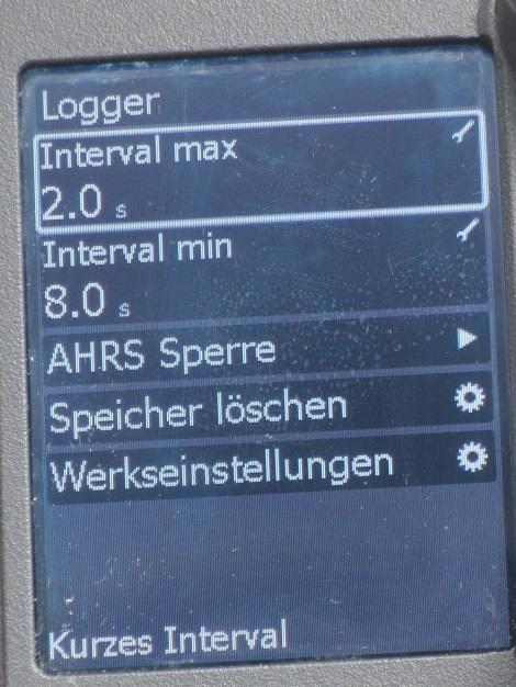
6 Menue : Setup / Voice / Limits Menue : Setup / Logger


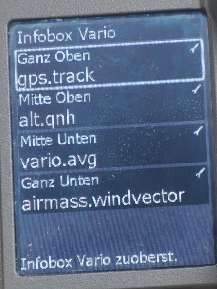
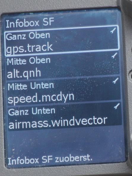

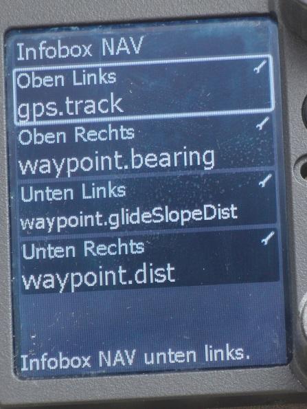

7 Menue : Setup / NMEA Einheit Menue : Setup / Gerät und Info-Boxen

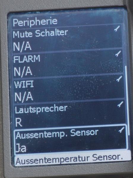
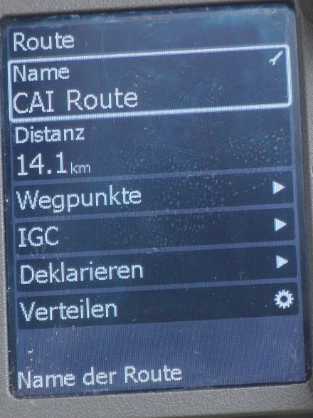
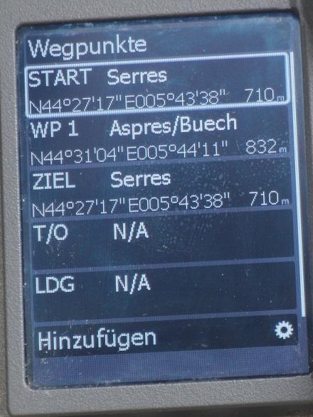
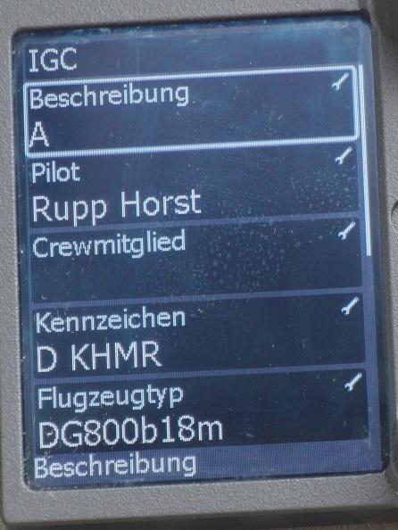
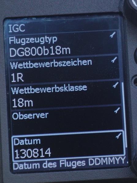
8 Menue : Setup / Peripherie Menue : Setup / Route Wegpunkte - IGC

9 In expert mode (press ESC then Menue): Expert-Menue : Setup / ISU IAS CAS correction
Air Glide S without frustration?!
 Air Glide S without frustration?! Zuletzt aktualisiert am Sonntag, 08. Mai 2016 18:48 Veröffentlicht am Montag, 18. August 2014 16:47 Geschrieben von Horst After publishing an article on "How to set up
LX Compass module 3 Electronic compass device User manual
 LX Compass module 3 Electronic compass device User manual LX navigation d.o.o., Tkalska 10 SLO 3000 Celje, tel: + 386 3 490 46 70, fax: + 386 3 490 46 71 info@lxnavigation.si, http://www.lxnavigation.com
Flight Dynamics II (Stability) Prof. Nandan Kumar Sinha Department of Aerospace Engineering Indian Institute of Technology, Madras
 Prof. Nandan Kumar Sinha Department of Aerospace Engineering Indian Institute of Technology, Madras") Flight Dynamics II (Stability) Prof. Nandan Kumar Sinha Department of Aerospace Engineering Indian Institute of Technology, Madras Module No. # 13 Introduction to Aircraft Control Systems Lecture No. #
Flight Dynamics II (Stability) Prof. Nandan Kumar Sinha Department of Aerospace Engineering Indian Institute of Technology, Madras Module No. # 13 Introduction to Aircraft Control Systems Lecture No. #
Fail Operational Controls for an Independent Metering Valve
 Group 14 - System Intergration and Safety Paper 14-3 465 Fail Operational Controls for an Independent Metering Valve Michael Rannow Eaton Corporation, 7945 Wallace Rd., Eden Prairie, MN, 55347, email:
frequently asked questions
 Hydra Pilot Fault Codes What do the fault codes for the Hydra Pilot mean? Fault Cause FAULT 100 FAULT 101 FAULT 102 FAULT 103 FAULT 104 FAULT 105 FAULT 106 FAULT 108 FAULT 109 FAULT 110 FAULT 111 FAULT
Autopilot setup. VRF (Virtual Rudder Feedback) calibration. Software setup NSS evo2 Installation Manual
 calibration. Software setup NSS evo2 Installation Manual") Autopilot setup Verifying the autopilot connection When an AC12N, AC42N, or SG05 is connected to the NSS evo2 system, the NSS evo2 will automatically detect the autopilot and an Autopilot menu icon will
Autopilot setup Verifying the autopilot connection When an AC12N, AC42N, or SG05 is connected to the NSS evo2 system, the NSS evo2 will automatically detect the autopilot and an Autopilot menu icon will
AN31E Application Note
 Balancing Theory Aim of balancing How an unbalance evolves An unbalance exists when the principle mass axis of a rotating body, the so-called axis of inertia, does not coincide with the rotational axis.
Answer Key. Page 1 of 5. 1) What is the maximum flaps-extended speed? A. 100 MPH. B. 65 MPH. C. 165 MPH. 2) Altimeter 1 indicates
 What is the maximum flaps-extended speed? A. 100 MPH. B. 65 MPH. C. 165 MPH. 2) Altimeter 1 indicates") Name: Answer Key Score: 1) What is the maximum flaps-extended speed? A. 100 MPH. B. 65 MPH. C. 165 MPH. 2) Altimeter 1 indicates A. 10,500 feet. B. 1,500 feet. C. 500 feet. 3) In the Northern Hemisphere,
Name: Answer Key Score: 1) What is the maximum flaps-extended speed? A. 100 MPH. B. 65 MPH. C. 165 MPH. 2) Altimeter 1 indicates A. 10,500 feet. B. 1,500 feet. C. 500 feet. 3) In the Northern Hemisphere,
PERFORMANCE MANEUVERS
 Ch 09.qxd 5/7/04 8:14 AM Page 9-1 PERFORMANCE MANEUVERS Performance maneuvers are used to develop a high degree of pilot skill. They aid the pilot in analyzing the forces acting on the airplane and in
Lesson: Pitch Trim. Materials / Equipment Publications o Flight Training Manual for Gliders (Holtz) Lesson 4.4 Using the Trim Control.
 Lesson 4.4 Using the Trim Control.") 11/18/2015 Pitch Trim Page 1 Lesson: Pitch Trim Objectives: o Knowledge o An understanding of the aerodynamics related to longitudinal (pitch) stability o Skill o Use of the pitch trim system to control
11/18/2015 Pitch Trim Page 1 Lesson: Pitch Trim Objectives: o Knowledge o An understanding of the aerodynamics related to longitudinal (pitch) stability o Skill o Use of the pitch trim system to control
Lesson: Airspeed Control
 11/20/2018 Airspeed Control Page 1 Lesson: Airspeed Control Objectives: o Knowledge o An understanding of the aerodynamics related to airspeed control o Skill o The ability to establish and maintain a
NORMAL TAKEOFF AND CLIMB
 NORMAL TAKEOFF AND CLIMB CROSSWIND TAKEOFF AND CLIMB The normal takeoff is one in which the airplane is headed directly into the wind or the wind is very light, and the takeoff surface is firm with no
A Performanced Based Angle of Attack Display
 A Performanced Based Angle of Attack Display David F. Rogers, Phd, ATP www.nar-associates.com The Problem The current angle of attack displays basically warn you about the approach to stall with yellow
II.E. Airplane Flight Controls
 References: FAA-H-8083-3; FAA-8083-3-25 Objectives Key Elements Elements Schedule Equipment IP s Actions SP s Actions Completion Standards The student should develop knowledge of the elements related to
Attitude Instrument Flying and Aerodynamics
 Attitude Instrument Flying and Aerodynamics 2.1 TURNS 1. An airplane requires a sideward force to make it turn. a. When the airplane is banked, lift (which acts perpendicular to the wingspan) acts not
REACTOR 40 MECHANICAL Configuration Guide
 REACTOR 40 MECHANICAL Configuration Guide Important Safety Information WARNING See the Important Safety and Product Information guide in the product box for product warnings and other important information.
NORMAL TAKEOFF PILOT TRAINING MANUAL KING AIR 200 SERIES OF AIRCRAFT
 NORMAL TAKEOFF Climb-Out 1. Accelerate to 160 KIAS 2. Landing/Taxi lights: Out 3. Climb Checklist complete 1. 160 KIAS up to 10,000 ft 2. Decrease 2 KIAS per 1,000 ft above 10,000 ft to 130 KIAS at 25,000
Constant Pressure Inlet (CCN) Operator Manual
 Operator Manual") Constant Pressure Inlet (CCN) Operator Manual DOC-0125 Revision J 2545 Central Avenue Boulder, CO 80301-5727 USA C O P Y R I G H T 2 0 1 1 D R O P L E T M E A S U R E M E N T T E C H N O L O G I E S, I
Constant Pressure Inlet (CCN) Operator Manual DOC-0125 Revision J 2545 Central Avenue Boulder, CO 80301-5727 USA C O P Y R I G H T 2 0 1 1 D R O P L E T M E A S U R E M E N T T E C H N O L O G I E S, I
Visualized Flight Maneuvers Handbook
 Visualized Flight Maneuvers Handbook For High Wing Aircraft Third Edition For Instructors and Students Aviation Supplies & Academics, Inc. Newcastle, Washington Visualized Flight Maneuvers Handbook for
Fail operational controls for an independent metering valve
 Failure mode and CMA valves Fail operational controls for an independent metering valve By: Michael Rannow email: michaelrannow@eaton.com Eaton Corporation, 7945 Wallace Rd. Eden Prairie, MN, 55347 As
PROCEDURES GUIDE. FLIGHT MANEUVERS for the SPORT PILOT
 Page 1 of 10 PROCEDURES GUIDE FLIGHT MANEUVERS for the SPORT PILOT * Author s Note: Whereas this procedures guide has been written for a specific application, it can easily be modified to fit many different
Improvement of an Artificial Stall Warning System for Sailplanes
 Improvement of an Artificial Stall Warning System for Sailplanes Loek M. M. Boermans and Bart Berendsen Delft University of Technology, Faculty of Aerospace Engineering P.O.Box 5058, 2600 GB Delft, The
Basics of Speed to Fly for Paragliding Pilots
 Page 1 of 10 San Francisco and Northern California's Premier Paragliding School Up is GOOD!!! Basics of Speed to Fly for Paragliding Pilots The expression Speed to Fly represents the adjustments to a Paraglider's
VI.A-E. Basic Attitude Instrument Flight
 References: FAA-H-8083-3; FAA-8083-3-15 Objectives Key Elements Elements Schedule Equipment IP s Actions SP s Actions Completion Standards The student should develop knowledge of the elements related to
Front Cover Picture Mark Rasmussen - Fotolia.com
 Flight Maneuvers And Stick and Rudder Skills A complete learn to fly handbook by one of aviation s most knowledgeable and experienced flight instructors Front Cover Picture Mark Rasmussen - Fotolia.com
One of the most important gauges on the panel is
 stick & rudder flight advisor Is Your Airspeed Indicator Honest? An accuracy how-to H.C. SKIP SMITH One of the most important gauges on the panel is the airspeed indicator. This is particularly true if
BAPI Pressure Line of Products - FAQs
 Table of Contents 1. Several manufacturers produce pressure transmitters, why should I purchase from BAPI?... p. 2 2. BAPI makes several styles of pressure transmitters. What are the features of each?...
Review of. Bell B206 Replica Torque Pedals. Manufactured by OE-XAM
 Review of Bell B206 Replica Torque Pedals Manufactured by OE-XAM Intro During my quest around flight simulation hardware I have set my focus on hardware manufactured specifically for helicopter flight
TR Electronic Pressure Regulator. User s Manual
 TR Electronic Pressure Regulator Page 2 of 13 Table of Contents Warnings, Cautions & Notices... 3 Factory Default Setting... 4 Quick Start Procedure... 5 Configuration Tab... 8 Setup Tab... 9 Internal
Line Following with RobotC Page 1
 Line Following with RobotC Page 1 Line Following with By Michael David Lawton Introduction Line following is perhaps the best way available to VEX Robotics teams to quickly and reliably get to a certain
Ops Manual 05 Page 40
 Ops Manual 05 Page 40 Ops Manual 05 Pg 41 I. PRE -FLIGHT PREPARATION. (a) EXTERNAL CHECKS --Before entering the cockpit, a detailed inspection of the sailplane for proper condition should be carried out
Principles of glider flight
 Principles of glider flight [ Lecture 2: Control and stability ] Richard Lancaster Email: Richard@RJPLancaster.net Twitter: @RJPLancaster ASK-21 illustrations Copyright 1983 Alexander Schleicher GmbH &
Winnipeg Headingley Aero Modellers. Things About Airplanes.
 Winnipeg Headingley Aero Modellers Things About Airplanes. Table of Contents Introduction...2 The Airplane...2 How the Airplane is Controlled...3 How the Airplane Flies...6 Lift...6 Weight...8 Thrust...9
"Aircraft setup is a constant process really. Every
 The R/C Aircraft Proving Grounds - Aerobatics Setup Set Up for Success by: Douglas Cronkhite "Aircraft setup is a constant process really. Every time something is changed, there is the chance it will affect
CIVIL AIR PATROL United States Air Force Auxiliary Cadet Program Directorate. Cessna 172 Maneuvers and Procedures
 CIVIL AIR PATROL United States Air Force Auxiliary Cadet Program Directorate Cessna 172 Maneuvers and Procedures This study guide is designed for the National Flight Academy Ground School. The information
Tecnam Eaglet Standard Operating Procedures and Maneuvers Supplement
 Tecnam Eaglet Standard Operating Procedures and Maneuvers Supplement Normal Takeoff Flaps Take Off Trim set Fuel pump on Check for traffic Line up on white stripe Full power Stick should be located in
Cessna 152 Standardization Manual
 Cessna 152 Standardization Manual This manual is to be utilized in conjunction with the manufacturers approved POH/ AFM and the Airplane Flying Handbook (FAA-H-8083-3A). This manual should be used as a
Accident Prevention Program
 Accident Prevention Program SAFE FLYING FOR AGRICULTURAL AVIATION By Ansel H. McAllaster The basic safety elements, method for executing an applicator swath run and turnaround at the end of a swath run,
MANEUVERS GUIDE. Liberty Aerospace 1383 General Aviation Drive Melbourne, FL (800)
") MANEUVERS GUIDE Liberty Aerospace 1383 General Aviation Drive Melbourne, FL 32935 (800) 759-5953 www.libertyaircraft.com Normal/Crosswind Takeoff and Climb 1. Complete the runup and before takeoff checklist.
MANEUVERS GUIDE Liberty Aerospace 1383 General Aviation Drive Melbourne, FL 32935 (800) 759-5953 www.libertyaircraft.com Normal/Crosswind Takeoff and Climb 1. Complete the runup and before takeoff checklist.
Overview. 2 Module 13: Advanced Data Processing
 2 Module 13: Advanced Data Processing Overview This section of the course covers advanced data processing when profiling. We will discuss the removal of the fairly gross effects of ship heave and talk
Cessna 172S Skyhawk Standardization Manual
 Cessna 172S Skyhawk Standardization Manual This manual is to be utilized in conjunction with the manufacturers approved POH/ AFM and the Airplane Flying Handbook (FAA-H-8083-3A). This manual should be
XII.A-D. Basic Attitude Instrument Flight
 References: FAA-H-8083-3; FAA-8083-3-15 Objectives Key Elements Elements Schedule Equipment IP s Actions SP s Actions Completion Standards The student should develop knowledge of the elements related to
Task of this Manual. This manual applies to all standard instruments of the SB-7 type from serial number 5515 onwards (Manufacturer's code SB-702 )
") 2 Task of this Manual This manual gives all information required by the owner or user to understand the functioning of the instrument, to install it, and if necessary to program it, to maintain it, and
2 Task of this Manual This manual gives all information required by the owner or user to understand the functioning of the instrument, to install it, and if necessary to program it, to maintain it, and
FAA-S-ACS-6 June 2016 Private Pilot Airplane Airman Certification Standards. Task ACS Settings
 FAA-S-ACS-6 June 2016 Private Pilot Airplane Airman Certification Standards Cessna 172: mixture rich, carb heat out if below the green arc. Clearing Turns all manuevers! Task ACS Settings Traffic Pattern
Pre Solo Written For Schweizer 2-33 Glider. Eagles Sport Aviation Club
 Pre Solo Written For Schweizer 2-33 Glider Eagles Sport Aviation Club Student Date: Instructor 1) What is the maximum gross weight for the 2-33? Empty Weight? 2) What position should the trim level be
Stability and Flight Controls
 Stability and Flight Controls Three Axes of Flight Longitudinal (green) Nose to tail Lateral (blue) Wing tip to Wing tip Vertical (red) Top to bottom Arm Moment Force Controls The Flight Controls Pitch
Discuss: 1. Instrument Flight Checklist
 INST 1 Prerequisites: 1. OFT: Tac 1 2. CBT: Basic Instrument Flight, IFR Navigation I & II Lessons P2 501, P2 502, & P2 503. Discuss: 1. Instrument Flight Checklist NATOPS 13.1.3 Instrument Flight Checklist
FLIGHT PERFORMANCE AND PLANNING (2) PERFORMANCE
 PERFORMANCE") 1 Any acceleration in climb, with a constant power setting, A improves the climb gradient if the airspeed is below VX. B decreases the rate of climb and the angle of climb. C decreases rate of climb and
1 Any acceleration in climb, with a constant power setting, A improves the climb gradient if the airspeed is below VX. B decreases the rate of climb and the angle of climb. C decreases rate of climb and
Detailed study 3.4 Topic Test Investigations: Flight
 Name: Billanook College Detailed study 3.4 Topic Test Investigations: Flight Ivanhoe Girls Grammar School Questions 1 and 2 relate to the information shown in the diagram in Figure 1. z Question 1 y Figure
Deploying the TCM-1 Tilt Current Meter in an Inverted (Hanging) Orientation By: Nick Lowell, Founder & President
 Orientation By: Nick Lowell, Founder & President") Lowell Instruments Application Note #TCMA Deploying the TCM-1 Tilt Current Meter in an Inverted (Hanging) Orientation By: Nick Lowell, Founder & President 1 Introduction The TCM-1 Tilt Current Meter (TCM)
Lowell Instruments Application Note #TCMA Deploying the TCM-1 Tilt Current Meter in an Inverted (Hanging) Orientation By: Nick Lowell, Founder & President 1 Introduction The TCM-1 Tilt Current Meter (TCM)
Low Flying Introduction
 Advanced Manoeuvres Low Flying Introduction Commonly, low flying refers to any flight at or below 500 feet agl that may be practised only in designated low flying zones. By maintaining good situational
Trimming and Flying a Hand Launch Glider A basic and beginners guide by Kevin Moseley
 Trimming and Flying a Hand Launch Glider A basic and beginners guide by Kevin Moseley First and foremost, I am by no means a master at what I have done, or do, in hlg or the class. I am fortunate enough
Installation and Operation Manual
 Manual Static pressure transducer with controller Differential static pressure transducer with analog output and optional PI control mode Large diaphragm element with differential transformer Transducer
RM-80 respiration monitor
 RM-80 respiration monitor User Manual September 18, 2015 0025-003M 950 North Hague Avenue Columbus, Ohio 43204-2121 USA Sales: sales@colinst.com Service: service@colinst.com Phone: (614) 276-0861 Fax:
Wiimote Visualization Through Particles
 1 Abstract Wiimote Visualization Through Particles Joshua Jacobson Since 2006, the Wii video game console has been found within homes throughout out the world. The Wiimote exists as the primary input method
Compass Use. Objective To turn accurately onto and maintain compass headings, compensating for known errors in the magnetic compass.
 Instrument Flying Compass Use The magnetic compass is the primary navigation aid for most light aeroplanes. It is the only instrument in most light aeroplanes that indicates the correct heading. The directional
LAPL(A)/PPL(A) question bank FCL.215, FCL.120 Rev PRINCIPLES OF FLIGHT 080
/PPL(A) question bank FCL.215, FCL.120 Rev PRINCIPLES OF FLIGHT 080") PRINCIPLES OF FLIGHT 080 1 Density: Is unaffected by temperature change. Increases with altitude increase. Reduces with temperature reduction. Reduces with altitude increase. 2 The air pressure that acts
PRINCIPLES OF FLIGHT 080 1 Density: Is unaffected by temperature change. Increases with altitude increase. Reduces with temperature reduction. Reduces with altitude increase. 2 The air pressure that acts
Brief Maintenance Manual DAR-Solo
 Brief Maintenance Manual DAR-Solo Sofia 2009 Page: 1 TABLE OF CONTENTS Introduction 3 Limitations and safety information 4 General view of DAR-Solo prototype 7 Technical Data 8 Inspection before and after
The Discussion of this exercise covers the following points: Range with an elevated or suppressed zero Suppressed-zero range Elevated-zero range
 Exercise 4-3 Zero Suppression and Zero Elevation EXERCISE OBJECTIVE In this exercise, you will learn the effect that mounting a pressure transmitter above or below the reference level has on the hydrostatic
IVAO International Virtual Aviation Organization Training department
 1 Introduction IVAO International Virtual Aviation Organization Training department TRAFFIC PATTERN DESCRIPTION An aerodrome traffic pattern is used by VFR traffic for training purpose or to prepare the
Operating instructions for. For visualization of your measurements
 Operating instructions for For visualization of your measurements FermVis operating instructions Important message In the interest of preventing operator errors and incorrect measurement results, you must
Cessna 172R Profiles
 Cessna 172R Profiles TRAFFIC PATTERNS (Verify pattern altitude) Start your first climbing turn within 300' of pattern altitude Enter 45 degree angle to the downwind leg Depart the traffic pattern straight-out,
FFI Formation Guidelines and Standard Procedures Mooney Supplement (28 Dec, 2018; Rev 12)
") FFI Formation Guidelines and Standard Procedures Mooney Supplement (28 Dec, 2018; Rev 12) This document describes formation flight differences between RV and Mooney aircraft. In conjunction with the FFI
FFI Formation Guidelines and Standard Procedures Mooney Supplement (28 Dec, 2018; Rev 12) This document describes formation flight differences between RV and Mooney aircraft. In conjunction with the FFI
SWS Option: Well Pressures. SWS Option: Stretch Correction (Corrected depth) SWS Option: MMD (Magnetic Marks Detection) ASEP Products
 SWS Option: MMD (Magnetic Marks Detection) ASEP Products") SWS Option: Well Pressures PART NUMBER L-8531039779 The SmartMonitor can simultaneously measure, display and record depth and up to four different well pressures (for example, Control Line Pressure, Tubing
SWS Option: Well Pressures PART NUMBER L-8531039779 The SmartMonitor can simultaneously measure, display and record depth and up to four different well pressures (for example, Control Line Pressure, Tubing
Model 130M Pneumatic Controller
 Instruction MI 017-450 May 1978 Model 130M Pneumatic Controller Installation and Operation Manual Control Unit Controller Model 130M Controller is a pneumatic, shelf-mounted instrument with a separate
Flightlab Ground School 7. Longitudinal Dynamic Stability
 Flightlab Ground School 7. Longitudinal Dynamic Copyright Flight Emergency & Advanced Maneuvers Training, Inc. dba Flightlab, 2009. All rights reserved. For Training Purposes Only Introduction to is the
XI.C. Power-Off Stalls
 References: FAA-H-8083-3; POH/AFM Objectives Key Elements Elements Schedule Equipment IP s Actions SP s Actions Completion Standards The student should develop knowledge of stalls regarding aerodynamics,
LAPL/PPL question bank FCL.215, FCL.120 Rev PRINCIPLES OF FLIGHT 080
 LAPL/PPL question bank FCL.215, FCL.120 Rev. 1.7 11.10.2018 PRINCIPLES OF FLIGHT 080 1 Density: Reduces with temperature reduction. Increases with altitude increase. Reduces with altitude increase. Is
Introduction. The Shearwater Petrel is an advanced technical diving computer for open and closed circuit divers.
 Introduction The Shearwater Petrel is an advanced technical diving computer for open and closed circuit divers. Although we strive to make the Petrel easy enough to use without reading the manual, please
Flight Profiles are designed as a guideline. Power settings are recommended and subject to change based
 MANEUVERS AND PROCEDURES Flight Profiles are designed as a guideline. Power settings are recommended and subject to change based upon actual conditions (i.e. aircraft weight, pressure altitude, icing conditions,
Bench Trimming A Stunt Ship
 Bench Trimming A Stunt Ship by Brett Buck "Bench Trimming" - this refers to setting up the initial trim of the airplane in the shop prior to flight. Since people have been flying stunt in its current form
485 Annubar Primary Flow Element Installation Effects
 ROSEMOUNT 485 ANNUBAR 485 Annubar Primary Flow Element Installation Effects CONTENTS Mounting hole diameter Alignment error Piping Geometry Induced Flow Disturbances Pipe reducers and expansions Control
I2103 WORKSHEET. Planned Route: Takeoff: KNSE, RWY 32 Altitude: 12,000 Route: RADAR DEPARTURE. Syllabus Notes None
 Planned Route: Takeoff: KNSE, RWY 32 Altitude: 12,000 Route: RADAR DEPARTURE Syllabus Notes None I2103 WORKSHEET Special Syllabus Requirements Proceed direct to homefield using any available NAVAID. Discuss
Takeoffs & Landings Refresher. By Wally Moran
 Takeoffs & Landings Refresher By Wally Moran About Wally Moran Wally Moran is a retired airline captain and spent much of his career as a training instructor and check airman on aircraft including the
Instruction Manual Dräger MSI P7 and MSI P7 plus
 Dräger MSI GmbH Rohrstraße 32 58093 Hagen Tel.: +49-2331 / 9584-0 Fax: +49-2331 / 9584-29 e-mail: info@draeger-msi.de D 923; Edition 2011-01-01 Content 1. General Hints Page 4 2. The Instrument 2.1 Front
Southern Eagles Soaring
 Southern Eagles Soaring N56LS Standard Cirrus Disassembly / Assembly Procedure. Version 2, 2017 You landed out so what now? First, hopefully you made arrangements with someone who has a hitch on their
SECTION 6-16 FLIGHT INSTRUMENTS
 SECTION 6-16 SYSTEMS DESCRIPTION Index Page Pitot-Static System... 6-16-2 Airspeed Indicator... 6-16-4 Vertical Speed Indicator... 6-16-4 Instantaneous Vertical Speed Indicator IVSI (Optional)... 6-16-5
Transparent mode In transparent mode (OFF) autopilot transmits signals from the receiver directly to the servos and motor controller.
 autopilot transmits signals from the receiver directly to the servos and motor controller.") Step by step autopilot setup instructions Autopilot control signals Autopilot is controlled by typical PPM signals sent directly from the RC receiver. The system can be connected by a multicore cable directly
Step by step autopilot setup instructions Autopilot control signals Autopilot is controlled by typical PPM signals sent directly from the RC receiver. The system can be connected by a multicore cable directly
VFR Circuit Tutorial. A Hong Kong-based Virtual Airline. VOHK Training Team Version 2.1 Flight Simulation Use Only 9 July 2017
 A Hong Kong-based Virtual Airline VFR Circuit Tutorial VOHK Training Team Version 2.1 Flight Simulation Use Only 9 July 2017 Copyright 2017 Oasis Hong Kong Virtual Page 1 Oasis Hong Kong Virtual (VOHK)
Preliminary Design Review (PDR) Aerodynamics #2 AAE-451 Aircraft Design
 Aerodynamics #2 AAE-451 Aircraft Design") Preliminary Design Review (PDR) Aerodynamics #2 AAE-451 Aircraft Design Aircraft Geometry (highlight any significant revisions since Aerodynamics PDR #1) Airfoil section for wing, vertical and horizontal
Preliminary Design Review (PDR) Aerodynamics #2 AAE-451 Aircraft Design Aircraft Geometry (highlight any significant revisions since Aerodynamics PDR #1) Airfoil section for wing, vertical and horizontal
Ideal gas law. Introduction
 Ideal gas law Introduction We think of a gas as a collection of tiny particles in random, thermal motion. When they collide with the sides of a container, they exert a force on the container walls. The
CIRCLING THE HOLIGHAUS WAY -
 CIRCLING THE HOLIGHAUS WAY - OR DO YOU REALLY WANT TO KEEP THE YAW STRING CENTERED? BY RICHARD H. JOHNSON ANSWERS: 1. During Straight Flight - YES, that minimizes drag and maximizes the sailplane's performance.
Cessna 172 Profiles. TRAFFIC PATTERNS (Check Chart Supplement prior to flight) Index
 Index") Cessna 172 Profiles TRAFFIC PATTERNS (Check Chart Supplement prior to flight) Index When Cleared for Takeoff - Landing/Taxi lights ON Mixture-As Required Power-Check Takeoff RPM Power Climb at Vy Start
Cessna 172 Profiles TRAFFIC PATTERNS (Check Chart Supplement prior to flight) Index When Cleared for Takeoff - Landing/Taxi lights ON Mixture-As Required Power-Check Takeoff RPM Power Climb at Vy Start
Cover Page for Lab Report Group Portion. Pump Performance
 Cover Page for Lab Report Group Portion Pump Performance Prepared by Professor J. M. Cimbala, Penn State University Latest revision: 02 March 2012 Name 1: Name 2: Name 3: [Name 4: ] Date: Section number:
Compiled by Matt Zagoren
 The information provided in this document is to be used during simulated flight only and is not intended to be used in real life. Attention VA's - you may post this file on your site for download. Please
IBU3 Manual Addendum 1
 This addendum covers the follow items. Connection of airsoft micro switch Connection of Taigen airsoft recoil units Selecting airsoft mode Settings for clutch style gearboxes Motor enable selection Confirmation
Aerodynamic Terms. Angle of attack is the angle between the relative wind and the wing chord line. [Figure 2-2] Leading edge. Upper camber.
![Aerodynamic Terms. Angle of attack is the angle between the relative wind and the wing chord line. [Figure 2-2] Leading edge. Upper camber.](/thumbs/82/86661300.jpg "Aerodynamic Terms. Angle of attack is the angle between the relative wind and the wing chord line. [Figure 2-2] Leading edge. Upper camber.") Chapters 2 and 3 of the Pilot s Handbook of Aeronautical Knowledge (FAA-H-8083-25) apply to powered parachutes and are a prerequisite to reading this book. This chapter will focus on the aerodynamic fundamentals
Chapters 2 and 3 of the Pilot s Handbook of Aeronautical Knowledge (FAA-H-8083-25) apply to powered parachutes and are a prerequisite to reading this book. This chapter will focus on the aerodynamic fundamentals
BRITISH MICROLIGHT AIRCRAFT ASSOCIATION SERVICE BULLETIN
 BRITISH MICROLIGHT AIRCRAFT ASSOCIATION SERVICE BULLETIN Reference: BMAA Service Bulletin 2624 issue 1 Title: Savannah Pitch Control and Trim Systems Configuration Applicability: All UK Savannah MXP-740
CCT-7320/ROC-2313 Reverse Osmosis Controller
 CCT-7320/ROC-2313 Reverse Osmosis Controller 1 General The instrument is a combined control instrument of a reverse osmosis controller and an on-line conductivity instrument. It can perform the operation
TECHNIQUES FOR OFF AIRPORT OPERATIONS
 Off Airport Ops Guide TECHNIQUES FOR OFF AIRPORT OPERATIONS Note: This document suggests techniques and procedures to improve the safety of off-airport operations. It assumes that pilots have received
Operating instructions Pitot Static Tube
 Operating instructions Pitot Static Tube halstrup-walcher GmbH Stegener Straße 10 D-79199 Kirchzarten, Germany Phone: +49 (0) 76 61/39 63-0 Fax: +49 (0) 76 61/39 63-99 E-mail: info@halstrup-walcher.de
VIII.A. Straight and Level Flight
 VIII.A. Straight and Level Flight References: FAA-H-8083-3; FAA-H-8083-25 Objectives Key Elements Elements Schedule Equipment IP s Actions SP s Actions Completion Standards The student should develop the
9A5N Solid State CW Paddle
 9A5N Solid State CW Paddle User manual Table of contents: 1. General description 2. Before you begin 3. Finger piece and/or battery installation 4. Interconnection 5. Lever(s) sensitivity adjustment 6.
TAKEOFF & LANDING IN ICING CONDITIONS
 Original idea from Captain A. Wagner T TAKEOFF & LANDING IN ICING CONDITIONS here have been a number of accidents related to take-off in conditions in which snow and/or other forms of freezing precipitation
Airbus Series Vol.2 (c) Wilco Publishing feelthere.com
 Wilco Publishing feelthere.com") Airbus Series Vol.2 (c) Wilco Publishing feelthere.com Frequently Asked Questions Fuel Planning The fuel planner has been improved (since Volume 2 SP1) and is now quite accurate. Nevertheless, you should
Airbus Series Vol.2 (c) Wilco Publishing feelthere.com Frequently Asked Questions Fuel Planning The fuel planner has been improved (since Volume 2 SP1) and is now quite accurate. Nevertheless, you should
DISCLAIMER: This scanned version of the Schweizer 2-33A Sailplane manual is provided without warranty of completeness or accuracy.
 DISCLAIMER: This scanned version of the Schweizer 2-33A Sailplane manual is provided without warranty of completeness or accuracy. It is solely as a service to builders of scale model aircraft who are
Lesson: Turning Flight. Prerequisites: Airspeed Control
 2/16/2016 Turning Flight Page 1 Lesson: Turning Flight Prerequisites: Airspeed Control Objectives: o Knowledge o An understanding of the aerodynamics related to directional (yaw) stability o A basic understanding
Standard League Robot Soccer EV3 Compass Training Curriculum Brian Thomas
 Standard League Robot Soccer EV3 Compass Training Curriculum Brian Thomas RoboCup Junior Australia Inc Copyright 2018 1 Standard League Robot Soccer EV3 Compass Training Welcome! The aim of this curriculum
Building Instructions ME 163 B 1a M 1:5 Turbine
 Building Instructions ME 163 B 1a M 1:5 Turbine Thank you for choosing our kit of the Me-163B. We ask you to read the instruction once in advance before building this kit in order to avoid mistakes. Make
STUDY OF LANDING TECHNIQUE DURING VISUAL APPROACH
 24 TH INTERNATIONAL CONGRESS OF THE AERONAUTICAL SCIENCES STUDY OF LANDING TECHNIQUE DURING VISUAL APPROACH Hiroshi TAKAHARA*, Takashi KONDO*, Shinji SUZUKI** *All Nippon Airways Co., LTD., **University