Air Glide S without frustration?!
|
|
|
- Henry Hoover
- 5 years ago
- Views:
Transcription

1 Air Glide S without frustration?! Zuletzt aktualisiert am Sonntag, 08. Mai :48 Veröffentlicht am Montag, 18. August :47 Geschrieben von Horst After publishing an article on "How to set up Air Glide S" on this web site in German, I received comments indicating a large demand for a translation. I tried to do that - with mixed success. As I am not a native speaker I was happy that Richard Frawley from down-under helped me with a re-editing (let's be honest : it was a re-translation) to get rid of my soddy English. Thanks a bunch, Richard. The main reason for the demand for this article lies with the poor documentation, which leaves the owner of newly acquired variometers more or less alone. I have built variometers and flight computers for myself since In recent times I had my own computer tied up to a PNI compass, and my goal was to tweak it to give me a fast and accurate wind indication. Yet, besides the job my time was limited as were my abilities and possibilities to create complex PCBs, and so I did not fully succeed. When the Butterfly gang first presented their vario at the Deutscher Segelfliegertag in Darmstadt in 2012 (German Soaring Convention), it dawned to me immediately, that they had built the sensor platform I was striving for since years, without success. And so I placed my order right away.
2 The really new assets of this vario are the turn and acceleration sensors in all axes. Derived sensor values are combined in a complex algorithm to make up a quasi inertial platform. The algorithm is based on Kalman filtering. For those who are interrested, Kalman was a Hungarian mathematician who devised these numerical methods in the 1950-ies. As far as I know they are part of all inertial navigation systems. Now, Stefan Leutenegger and Sam Gisiger adapted them, in cooperation with Butterfly, for what in Butterfly jargon is called "AHRS", an inertial platform to derive athmospheric data (lateral wind, vertical movement). Back to my order: Like everybody else I had to wait for, as I felt, ages to receive the product, and then to be completely disappointed by what I got - or got not. Many of the features from the papers did not work : No automatic climb-cruise-switching, no usable SC-signal or audio, no usable wind, etc, etc. Beforehand I used a CAI 302, as my measure to judge the Butterfly by and it failed by far. So, through the complaints, I got in touch with the Butterfly people. Many of the problems I encountered in the Butterfly seemed to be old acquaintances of mine, pretty well remembered from my own years of experience in vario and flight computer construction attempts. And I dared to utter a hint or two. From the first reluctance to accept unsolicited advice, now after four years, the relation between the Butterflys and me has changed so that they take advantage of my experience and solid hints. I have proudly acquired the status of an alpha-plus to beta tester :-) I hope Marc Förderer is happy with my presentation of this modest influence I take on the ongoing Butterfly development. Now two years hence, with the emerging version 1.1 of the SW, IMHO the variometers is pretty fully fledged. My list of requirements and improvements is finite and cleared with Marc, and I know more or less with what priority what will when be added to the SW. But most importantly, as it is now with V1.1, the vario works perfectly, better than the CAI 302 which was my measure of things in this realm. The wind indication has a swiftness and accuracy not known in any other device. It is exactly the way I wanted it for 20 some years. The wind indication is so fast, that any Butterfly newcomer falls in doubt if that indication could be really true. But, according to my experience and after all my own doubts have evaporated, I can assure you the indications are correct, even when at a given moment they seem to be implausible. Concerning wind measurement, the Butterfly is from a different world. If we deem an indication implausible, this is due to the fact that until now we never saw such a fast indication, and we had a too simplified model of the wind field around us. Wind is by far not as homogeneous an air movement as we all thought. The only remaining itch I have is the SC and the SC indication. There is a lot of potential for improvement here, but I also know from Marc, that this is the topmost item on the list.
3 Now, after this lengthy introduction, here is my list of todo items in order to have a smoothly ticking Butterfly variometer. CONTINUED BELOW, ON NEXT PAGE
4 How to make my Air Glide S work properly Originally written by Horst Rupp. Many thanks to Richard Frawley who edited and retranslated this article into proper English. 2014/11/21. The basic prerequisite for the Air Glide S, in particular the AHRS part, to work properly so that the extraneous noise (gusts, wind shifts, perturbations etc) can be removed is to ensure that it is set up correctly. The instrument is very sensitive and the installation needs to be done in a way that ensures that only the correct inputs are being sensed. Most legacy instrument installations take all pressures from probes at the rudder fin. And most unfortunately, many of them use the total energy (TE) pressure from the fin to feed in parallel a mass-measurement variometer with a capacity flask (in Germany mostly a Winter) and a pressure sensor probe variometer such as the Air Glide S (no capacity flask). There are many publications indicating the deterioration (mostly damping) of the pressure sensor probe measurements by the stream of air mass in and out of the capacity flask. So, it is obviously a somewhat bad idea to do that to your Air Glide S. This interference with a mass measuring instruments is certainly not compliant with the above mentioned basic prerequisite. Fortunately, the Air Glide S can be compensated by total pressure (called electronic compensation as opposed to TE compensation). This is a new feature of the Air Glide S arriving with V 1.1. Total pressure and TE pressure carry more or less (depends on quality of probe) the same information - but for the sign : Total pressure is static pressure PLUS pitot pressure, TE pressure is static pressure MINUS pitot pressure (probe compensation factor (~)-1). Thus, for a modern flight computer like in the Air Glide S it is no problem to derive the compensation signal from total pressure (electronic compensation). The advantage of electronic compensation is twofold: It makes the tubing so much simpler and it gets rid of the above mentioned deterioration. You may reserve the existing TE compensation pressure for the mass measuring variometer, as in legacy installations, but there is no need for a TE compensation pressure connection necessary at the Air Glide S. If you go that avenue, you will end up with a free inlet at the Air Glide S sensor box. This inlet should then be connected to static pressure (in parallel to the dedicated static pressure inlet. In the Air Glide S setup there is a setting to tell the instrument it should use the electronic compensation method. The appropriate value in the Air Glide S setup has to be set to 100% (see details below).
5 According to my experience the vario function of Air Glide S speeds up by a factor of 2 3 when the TE probe is disconnected from a mass-measuring variometer and electronic compensation is used instead. In my plane I had to increase the damping factors. The most crucial point for the proper functioning of your Air Glide S is where and how the Air Glide S sensor box is fitted to your ship. The place to put the box must be free of all varying magnetic fields, be it the compass, moving magneto-metallic parts, or electrical gear or cables which run a lot of current and are switched on and off intermittently or periodically. There is an immediate yet coarse test for this condition. Switch to the horizon page and observe the compass course indication. Now move flaps, gear and brakes and rudder. The compass should stay stable. Then (except for the Air Glide S itself ) switch on and off your electronic gadgetry. Here also, the compass should stay stable. On top of that, the Air Glide S sensor box should be fixed exactly in flight axis and without any big elevation angle error (positive or negative) relative to the plane in even flight attitude. Sure, you will not be able to attain that with absolute accuracy. Small errors in azimuth are compensated by the algorithm described further down, small errors in elevation are not compensated but they are not really relevant. They do lead to a horizon picture in the Air Glide S display where the horizon is a bit high or low, but they do not prevent the AHRS from working.
6 Next step is the compass compensation flight : A pattern of 8, starting in direction north. Start with a full circle left at 40 bank. When reaching north again, immediately start another circle to the right at 40 bank. As you fly through the pattern the compass compensation quality indication should climb from 0 to 9. It might even go up and down a bit, but it should end at 8 or 9 when you are through the second circle and you straighten out for a north course again. The Air Glide S will eventually say compensated and it squeaks a bit, as the Kalman filters get new starting values and have to adjust. The system needs about 15 minutes to completely stabilize after the compensation before it becomes fully reliable. The Kalman filters are adaptive, that is to say the output of the inertial platform is getting better with usage time. You may check at once if the compensation was truly successful. Go to the horizon page, it should show an even horizon. If the horizon is askew, the compensation was no good. Don t be afraid when the compensation does not work the first time. Do it again. Only if after 5 tries you do not reach 8 or 9 as quality factor, look for a different location for the box or think about interfering factors which could be eliminated. After many trials I had to ban my AirPath compass from the cockpit. It always messed up the compensation. It took a while to find out. When, after you gave the system half an hour to settle, you fly an docile circle in calm air, you should see the wind arrow smoothly turn with your circle, and the wind speed should not vary by more than +-3 km/h. If the speed varies in a larger interval then you should consider using the IAS-CAS correction possibilities (see at the very end of the paper). It might happen that the total pressure measurement in your ship is a tiny bit off (it is so in most ships). There are two error sources for that : The air mass flowing along the fuselage is accelerated by the volume dislocation of the fuselage and it might still be a tiny bit fast in relation to the non-disturbed air around your ship when it hits the fin probe. If on your plane s static and total pressures happen to be taken from the nose and the side of the fuselage, there is a systematic mismeasurement of your plane s speed (most plane types show this behaviour, check your Owner s Flight Manual). When CAS at the sensor input is too big, then in the downwind part of a circle the wind will be calculated as too small, vice versa in the headwind part of the circle as too big.


7 All further preparations of the Air Glide S are done by configurations in the various SETUP-menus of the variometer. Be warned. It is easily possible to misconfigure the device in such a way that it can be rendered pretty much useless in flight. However, the below set of baseline setup values will give you acceptable results right away and you can always fall back to these values. This warning should not stop you from modifying and potentially optimising these values for your aircraft and flying style as you get acquainted with understanding how settings work and interact. Menue : Setup / Vario First picture : Speed command error filter set to 0.0 sec!! In this way the current SC indication works best IMHO. I am not happy with the SC signal behavior and I am in constant discussion with Butterfly about this issue. I do hope there will be improvements soon. Third picture : The plane DGNeu is from my own collection of polar curves (glider.xml). If you have no file glider.xml on the USB stick in subdirectory <polars>, then Butterfly uses a built-in collection of polar curves from which you can choose. The DG800 polar curve in that collection seemed a bit conservative for my taste. So I replaced it. TE Kompensation % means electronic compensation by total pressure. 0 % means compensation via TE probe. All values between -10 and 100 % are possible, indicating the mixture between the compensation sources. Butterfly recommends values of 100 % for electronic compensation and between -10 to +10 % for TE compensation (al gusto).


8 Menue : Setup / Voice First picture : SF Vario tunes. When selected, the SC audio is replaced by vario audio tunes during climb in cruise mode. There are three possible criteria to decide when the SC tune is replaced by the audio tune or you can select no tune replacement and you will always listen to the pipiep-pipiep-sc-audio signal. Menue : Setup / Voice in General and Setup / Voice Timing


9 Menue : Setup / Voice / Limits Menue : Setup / Logger


10 Menue : Setup / NMEA Einheit Menue : Setup / Gerät und Info-Boxen


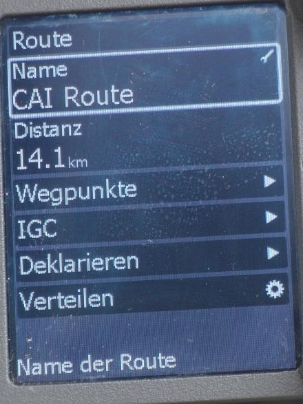


11 Menue : Setup / Peripherie Menue : Setup / Route Wegpunkte - IGC

12 In expert mode (press ESC then Menue): Expert-Menue : Setup / ISU IAS CAS correction
How to make my Air Glide S work properly
 How to make my Air Glide S work properly Originally written by Horst Rupp. Many thanks to Richard Frawley who edited and retranslated this article into proper English. 2014/11/21. The basic prerequisite
LX Compass module 3 Electronic compass device User manual
 LX Compass module 3 Electronic compass device User manual LX navigation d.o.o., Tkalska 10 SLO 3000 Celje, tel: + 386 3 490 46 70, fax: + 386 3 490 46 71 info@lxnavigation.si, http://www.lxnavigation.com
PERFORMANCE MANEUVERS
 Ch 09.qxd 5/7/04 8:14 AM Page 9-1 PERFORMANCE MANEUVERS Performance maneuvers are used to develop a high degree of pilot skill. They aid the pilot in analyzing the forces acting on the airplane and in
Flight Dynamics II (Stability) Prof. Nandan Kumar Sinha Department of Aerospace Engineering Indian Institute of Technology, Madras
 Prof. Nandan Kumar Sinha Department of Aerospace Engineering Indian Institute of Technology, Madras") Flight Dynamics II (Stability) Prof. Nandan Kumar Sinha Department of Aerospace Engineering Indian Institute of Technology, Madras Module No. # 13 Introduction to Aircraft Control Systems Lecture No. #
Flight Dynamics II (Stability) Prof. Nandan Kumar Sinha Department of Aerospace Engineering Indian Institute of Technology, Madras Module No. # 13 Introduction to Aircraft Control Systems Lecture No. #
One of the most important gauges on the panel is
 stick & rudder flight advisor Is Your Airspeed Indicator Honest? An accuracy how-to H.C. SKIP SMITH One of the most important gauges on the panel is the airspeed indicator. This is particularly true if
AN31E Application Note
 Balancing Theory Aim of balancing How an unbalance evolves An unbalance exists when the principle mass axis of a rotating body, the so-called axis of inertia, does not coincide with the rotational axis.
Autopilot setup. VRF (Virtual Rudder Feedback) calibration. Software setup NSS evo2 Installation Manual
 calibration. Software setup NSS evo2 Installation Manual") Autopilot setup Verifying the autopilot connection When an AC12N, AC42N, or SG05 is connected to the NSS evo2 system, the NSS evo2 will automatically detect the autopilot and an Autopilot menu icon will
Autopilot setup Verifying the autopilot connection When an AC12N, AC42N, or SG05 is connected to the NSS evo2 system, the NSS evo2 will automatically detect the autopilot and an Autopilot menu icon will
Fail Operational Controls for an Independent Metering Valve
 Group 14 - System Intergration and Safety Paper 14-3 465 Fail Operational Controls for an Independent Metering Valve Michael Rannow Eaton Corporation, 7945 Wallace Rd., Eden Prairie, MN, 55347, email:
II.E. Airplane Flight Controls
 References: FAA-H-8083-3; FAA-8083-3-25 Objectives Key Elements Elements Schedule Equipment IP s Actions SP s Actions Completion Standards The student should develop knowledge of the elements related to
Translation of 109 high speed trials. Spring Plane: 109 F with G wings W.Nr Original german text is included.
 Translation of 109 high speed trials Spring 1943 Plane: 109 F with G wings W.Nr. 9228 Original german text is included. What is so special about the 109 horizontal stabilizer trim? Like modern jets the
frequently asked questions
 Hydra Pilot Fault Codes What do the fault codes for the Hydra Pilot mean? Fault Cause FAULT 100 FAULT 101 FAULT 102 FAULT 103 FAULT 104 FAULT 105 FAULT 106 FAULT 108 FAULT 109 FAULT 110 FAULT 111 FAULT
Basics of Speed to Fly for Paragliding Pilots
 Page 1 of 10 San Francisco and Northern California's Premier Paragliding School Up is GOOD!!! Basics of Speed to Fly for Paragliding Pilots The expression Speed to Fly represents the adjustments to a Paraglider's
Answer Key. Page 1 of 5. 1) What is the maximum flaps-extended speed? A. 100 MPH. B. 65 MPH. C. 165 MPH. 2) Altimeter 1 indicates
 What is the maximum flaps-extended speed? A. 100 MPH. B. 65 MPH. C. 165 MPH. 2) Altimeter 1 indicates") Name: Answer Key Score: 1) What is the maximum flaps-extended speed? A. 100 MPH. B. 65 MPH. C. 165 MPH. 2) Altimeter 1 indicates A. 10,500 feet. B. 1,500 feet. C. 500 feet. 3) In the Northern Hemisphere,
Name: Answer Key Score: 1) What is the maximum flaps-extended speed? A. 100 MPH. B. 65 MPH. C. 165 MPH. 2) Altimeter 1 indicates A. 10,500 feet. B. 1,500 feet. C. 500 feet. 3) In the Northern Hemisphere,
A Performanced Based Angle of Attack Display
 A Performanced Based Angle of Attack Display David F. Rogers, Phd, ATP www.nar-associates.com The Problem The current angle of attack displays basically warn you about the approach to stall with yellow
Principles of glider flight
 Principles of glider flight [ Lecture 2: Control and stability ] Richard Lancaster Email: Richard@RJPLancaster.net Twitter: @RJPLancaster ASK-21 illustrations Copyright 1983 Alexander Schleicher GmbH &
Lesson: Airspeed Control
 11/20/2018 Airspeed Control Page 1 Lesson: Airspeed Control Objectives: o Knowledge o An understanding of the aerodynamics related to airspeed control o Skill o The ability to establish and maintain a
ZIPWAKE DYNAMIC TRIM CONTROL SYSTEM OUTLINE OF OPERATING PRINCIPLES BEHIND THE AUTOMATIC MOTION CONTROL FEATURES
 ZIPWAKE DYNAMIC TRIM CONTROL SYSTEM OUTLINE OF OPERATING PRINCIPLES BEHIND THE AUTOMATIC MOTION CONTROL FEATURES TABLE OF CONTENTS 1 INTRODUCTION 3 2 SYSTEM COMPONENTS 3 3 PITCH AND ROLL ANGLES 4 4 AUTOMATIC
PROCEDURES GUIDE. FLIGHT MANEUVERS for the SPORT PILOT
 Page 1 of 10 PROCEDURES GUIDE FLIGHT MANEUVERS for the SPORT PILOT * Author s Note: Whereas this procedures guide has been written for a specific application, it can easily be modified to fit many different
REACTOR 40 MECHANICAL Configuration Guide
 REACTOR 40 MECHANICAL Configuration Guide Important Safety Information WARNING See the Important Safety and Product Information guide in the product box for product warnings and other important information.
Lesson: Pitch Trim. Materials / Equipment Publications o Flight Training Manual for Gliders (Holtz) Lesson 4.4 Using the Trim Control.
 Lesson 4.4 Using the Trim Control.") 11/18/2015 Pitch Trim Page 1 Lesson: Pitch Trim Objectives: o Knowledge o An understanding of the aerodynamics related to longitudinal (pitch) stability o Skill o Use of the pitch trim system to control
11/18/2015 Pitch Trim Page 1 Lesson: Pitch Trim Objectives: o Knowledge o An understanding of the aerodynamics related to longitudinal (pitch) stability o Skill o Use of the pitch trim system to control
"Aircraft setup is a constant process really. Every
 The R/C Aircraft Proving Grounds - Aerobatics Setup Set Up for Success by: Douglas Cronkhite "Aircraft setup is a constant process really. Every time something is changed, there is the chance it will affect
Improvement of an Artificial Stall Warning System for Sailplanes
 Improvement of an Artificial Stall Warning System for Sailplanes Loek M. M. Boermans and Bart Berendsen Delft University of Technology, Faculty of Aerospace Engineering P.O.Box 5058, 2600 GB Delft, The
THERMALLING TECHNIQUES. Preface
 DRAFT THERMALLING TECHNIQUES Preface The following thermalling techniques document is provided to assist Instructors, Coaches and Students as a training aid in the development of good soaring skills. Instructors
Stability and Flight Controls
 Stability and Flight Controls Three Axes of Flight Longitudinal (green) Nose to tail Lateral (blue) Wing tip to Wing tip Vertical (red) Top to bottom Arm Moment Force Controls The Flight Controls Pitch
Constant Pressure Inlet (CCN) Operator Manual
 Operator Manual") Constant Pressure Inlet (CCN) Operator Manual DOC-0125 Revision J 2545 Central Avenue Boulder, CO 80301-5727 USA C O P Y R I G H T 2 0 1 1 D R O P L E T M E A S U R E M E N T T E C H N O L O G I E S, I
Constant Pressure Inlet (CCN) Operator Manual DOC-0125 Revision J 2545 Central Avenue Boulder, CO 80301-5727 USA C O P Y R I G H T 2 0 1 1 D R O P L E T M E A S U R E M E N T T E C H N O L O G I E S, I
CIRCLING THE HOLIGHAUS WAY -
 CIRCLING THE HOLIGHAUS WAY - OR DO YOU REALLY WANT TO KEEP THE YAW STRING CENTERED? BY RICHARD H. JOHNSON ANSWERS: 1. During Straight Flight - YES, that minimizes drag and maximizes the sailplane's performance.
Deploying the TCM-1 Tilt Current Meter in an Inverted (Hanging) Orientation By: Nick Lowell, Founder & President
 Orientation By: Nick Lowell, Founder & President") Lowell Instruments Application Note #TCMA Deploying the TCM-1 Tilt Current Meter in an Inverted (Hanging) Orientation By: Nick Lowell, Founder & President 1 Introduction The TCM-1 Tilt Current Meter (TCM)
Lowell Instruments Application Note #TCMA Deploying the TCM-1 Tilt Current Meter in an Inverted (Hanging) Orientation By: Nick Lowell, Founder & President 1 Introduction The TCM-1 Tilt Current Meter (TCM)
Overview. 2 Module 13: Advanced Data Processing
 2 Module 13: Advanced Data Processing Overview This section of the course covers advanced data processing when profiling. We will discuss the removal of the fairly gross effects of ship heave and talk
Preliminary Design Review (PDR) Aerodynamics #2 AAE-451 Aircraft Design
 Aerodynamics #2 AAE-451 Aircraft Design") Preliminary Design Review (PDR) Aerodynamics #2 AAE-451 Aircraft Design Aircraft Geometry (highlight any significant revisions since Aerodynamics PDR #1) Airfoil section for wing, vertical and horizontal
Preliminary Design Review (PDR) Aerodynamics #2 AAE-451 Aircraft Design Aircraft Geometry (highlight any significant revisions since Aerodynamics PDR #1) Airfoil section for wing, vertical and horizontal
Review of. Bell B206 Replica Torque Pedals. Manufactured by OE-XAM
 Review of Bell B206 Replica Torque Pedals Manufactured by OE-XAM Intro During my quest around flight simulation hardware I have set my focus on hardware manufactured specifically for helicopter flight
Fail operational controls for an independent metering valve
 Failure mode and CMA valves Fail operational controls for an independent metering valve By: Michael Rannow email: michaelrannow@eaton.com Eaton Corporation, 7945 Wallace Rd. Eden Prairie, MN, 55347 As
Instruction Manual Dräger MSI P7 and MSI P7 plus
 Dräger MSI GmbH Rohrstraße 32 58093 Hagen Tel.: +49-2331 / 9584-0 Fax: +49-2331 / 9584-29 e-mail: info@draeger-msi.de D 923; Edition 2011-01-01 Content 1. General Hints Page 4 2. The Instrument 2.1 Front
CIVIL AIR PATROL United States Air Force Auxiliary Cadet Program Directorate. Cessna 172 Maneuvers and Procedures
 CIVIL AIR PATROL United States Air Force Auxiliary Cadet Program Directorate Cessna 172 Maneuvers and Procedures This study guide is designed for the National Flight Academy Ground School. The information
Trimming and Flying a Hand Launch Glider A basic and beginners guide by Kevin Moseley
 Trimming and Flying a Hand Launch Glider A basic and beginners guide by Kevin Moseley First and foremost, I am by no means a master at what I have done, or do, in hlg or the class. I am fortunate enough
Accident Prevention Program
 Accident Prevention Program SAFE FLYING FOR AGRICULTURAL AVIATION By Ansel H. McAllaster The basic safety elements, method for executing an applicator swath run and turnaround at the end of a swath run,
Front Cover Picture Mark Rasmussen - Fotolia.com
 Flight Maneuvers And Stick and Rudder Skills A complete learn to fly handbook by one of aviation s most knowledgeable and experienced flight instructors Front Cover Picture Mark Rasmussen - Fotolia.com
NORMAL TAKEOFF PILOT TRAINING MANUAL KING AIR 200 SERIES OF AIRCRAFT
 NORMAL TAKEOFF Climb-Out 1. Accelerate to 160 KIAS 2. Landing/Taxi lights: Out 3. Climb Checklist complete 1. 160 KIAS up to 10,000 ft 2. Decrease 2 KIAS per 1,000 ft above 10,000 ft to 130 KIAS at 25,000
MANUAL. P C - C E N T E R Version Copyright by Dinand van het Reve CONTENTS
 P C - C E N T E R Version 4.00 Copyright 1995-2004 by Dinand van het Reve CONTENTS 1. Introduction 2. Installing PC-CENTER 3. Licence 4. Using PC-CENTER 5. Description of 'Small Windows' 6. Main Menu Description
Cessna 152 Standardization Manual
 Cessna 152 Standardization Manual This manual is to be utilized in conjunction with the manufacturers approved POH/ AFM and the Airplane Flying Handbook (FAA-H-8083-3A). This manual should be used as a
Test Glides Before Landing
 Test Glides Before Landing As soon as you achieve some comfort in the air, start preparing for the landing while you still have plenty of battery. Before attempting a landing, you should get acquainted
Attitude Instrument Flying and Aerodynamics
 Attitude Instrument Flying and Aerodynamics 2.1 TURNS 1. An airplane requires a sideward force to make it turn. a. When the airplane is banked, lift (which acts perpendicular to the wingspan) acts not
VI.A-E. Basic Attitude Instrument Flight
 References: FAA-H-8083-3; FAA-8083-3-15 Objectives Key Elements Elements Schedule Equipment IP s Actions SP s Actions Completion Standards The student should develop knowledge of the elements related to
Ops Manual 05 Page 40
 Ops Manual 05 Page 40 Ops Manual 05 Pg 41 I. PRE -FLIGHT PREPARATION. (a) EXTERNAL CHECKS --Before entering the cockpit, a detailed inspection of the sailplane for proper condition should be carried out
Pressure is our Business
 Pressure is our Business Count on gauges and calibrators that perform Wherever you work Reduce Measurement Error Protect against diminished accuracy from environmental conditions, accidental damage, and
Standard League Robot Soccer EV3 Compass Training Curriculum Brian Thomas
 Standard League Robot Soccer EV3 Compass Training Curriculum Brian Thomas RoboCup Junior Australia Inc Copyright 2018 1 Standard League Robot Soccer EV3 Compass Training Welcome! The aim of this curriculum
C-130 Reduction in Directional Stability at Low Dynamic Pressure and High Power Settings
 C-130 Reduction in Directional Stability at Low Dynamic Pressure and High Power Settings The C-130 experiences a marked reduction of directional stability at low dynamic pressures, high power settings,
TAKEOFF & LANDING IN ICING CONDITIONS
 Original idea from Captain A. Wagner T TAKEOFF & LANDING IN ICING CONDITIONS here have been a number of accidents related to take-off in conditions in which snow and/or other forms of freezing precipitation
NORMAL TAKEOFF AND CLIMB
 NORMAL TAKEOFF AND CLIMB CROSSWIND TAKEOFF AND CLIMB The normal takeoff is one in which the airplane is headed directly into the wind or the wind is very light, and the takeoff surface is firm with no
GEN II Robot Soccer EV3 Compass Training Curriculum Brian Thomas
 GEN II Robot Soccer EV3 Compass Training Curriculum Brian Thomas RoboCup Junior Australia Inc Copyright 2015 1 GEN II EV3 Robot Soccer Training Overview Welcome! The aim of this curriculum is to guide
Rules of Soccer Simulation League 2D
 Rules of Soccer Simulation League 2D (RoboCup2016 Leipzig, Germany) This document contains the rules for the RoboCup2016 Soccer Simulation League 2D competition in Leipzig, Germany. 1. Soccer Simulator
STUDY OF LANDING TECHNIQUE DURING VISUAL APPROACH
 24 TH INTERNATIONAL CONGRESS OF THE AERONAUTICAL SCIENCES STUDY OF LANDING TECHNIQUE DURING VISUAL APPROACH Hiroshi TAKAHARA*, Takashi KONDO*, Shinji SUZUKI** *All Nippon Airways Co., LTD., **University
485 Annubar Primary Flow Element Installation Effects
 ROSEMOUNT 485 ANNUBAR 485 Annubar Primary Flow Element Installation Effects CONTENTS Mounting hole diameter Alignment error Piping Geometry Induced Flow Disturbances Pipe reducers and expansions Control
Line Following with RobotC Page 1
 Line Following with RobotC Page 1 Line Following with By Michael David Lawton Introduction Line following is perhaps the best way available to VEX Robotics teams to quickly and reliably get to a certain
FLIGHT PERFORMANCE AND PLANNING (2) PERFORMANCE
 PERFORMANCE") 1 Any acceleration in climb, with a constant power setting, A improves the climb gradient if the airspeed is below VX. B decreases the rate of climb and the angle of climb. C decreases rate of climb and
1 Any acceleration in climb, with a constant power setting, A improves the climb gradient if the airspeed is below VX. B decreases the rate of climb and the angle of climb. C decreases rate of climb and
Introduction. The Shearwater Petrel is an advanced technical diving computer for open and closed circuit divers.
 Introduction The Shearwater Petrel is an advanced technical diving computer for open and closed circuit divers. Although we strive to make the Petrel easy enough to use without reading the manual, please
Viva TPS. TS11/15 Total Stations Check and Adjust Procedure. October Summary
 Viva TPS October 2010 TS11/15 Total Stations Summary Leica builds total stations to the highest quality and calibrates each instrument before it leaves the Factory. After the instrument is shipped or used
Transparent mode In transparent mode (OFF) autopilot transmits signals from the receiver directly to the servos and motor controller.
 autopilot transmits signals from the receiver directly to the servos and motor controller.") Step by step autopilot setup instructions Autopilot control signals Autopilot is controlled by typical PPM signals sent directly from the RC receiver. The system can be connected by a multicore cable directly
Step by step autopilot setup instructions Autopilot control signals Autopilot is controlled by typical PPM signals sent directly from the RC receiver. The system can be connected by a multicore cable directly
Operating instructions Pitot Static Tube
 Operating instructions Pitot Static Tube halstrup-walcher GmbH Stegener Straße 10 D-79199 Kirchzarten, Germany Phone: +49 (0) 76 61/39 63-0 Fax: +49 (0) 76 61/39 63-99 E-mail: info@halstrup-walcher.de
SECTION 6-16 FLIGHT INSTRUMENTS
 SECTION 6-16 SYSTEMS DESCRIPTION Index Page Pitot-Static System... 6-16-2 Airspeed Indicator... 6-16-4 Vertical Speed Indicator... 6-16-4 Instantaneous Vertical Speed Indicator IVSI (Optional)... 6-16-5
2018 Basic Known Guide IMAC Judge s Training
 2018 Basic Known Guide IMAC Judge s Training Gary Hunt: Graphics / Layout IMAC North Central, Art Director Ty Lyman: Rules Check / Layout IMAC Chief Judging Instructor 1) Aileron Roll. 2) Hammerhead /
Winnipeg Headingley Aero Modellers. Things About Airplanes.
 Winnipeg Headingley Aero Modellers Things About Airplanes. Table of Contents Introduction...2 The Airplane...2 How the Airplane is Controlled...3 How the Airplane Flies...6 Lift...6 Weight...8 Thrust...9
Visualized Flight Maneuvers Handbook
 Visualized Flight Maneuvers Handbook For High Wing Aircraft Third Edition For Instructors and Students Aviation Supplies & Academics, Inc. Newcastle, Washington Visualized Flight Maneuvers Handbook for
Bench Trimming A Stunt Ship
 Bench Trimming A Stunt Ship by Brett Buck "Bench Trimming" - this refers to setting up the initial trim of the airplane in the shop prior to flight. Since people have been flying stunt in its current form
SWS Option: Well Pressures. SWS Option: Stretch Correction (Corrected depth) SWS Option: MMD (Magnetic Marks Detection) ASEP Products
 SWS Option: MMD (Magnetic Marks Detection) ASEP Products") SWS Option: Well Pressures PART NUMBER L-8531039779 The SmartMonitor can simultaneously measure, display and record depth and up to four different well pressures (for example, Control Line Pressure, Tubing
SWS Option: Well Pressures PART NUMBER L-8531039779 The SmartMonitor can simultaneously measure, display and record depth and up to four different well pressures (for example, Control Line Pressure, Tubing
Cessna 172S Skyhawk Standardization Manual
 Cessna 172S Skyhawk Standardization Manual This manual is to be utilized in conjunction with the manufacturers approved POH/ AFM and the Airplane Flying Handbook (FAA-H-8083-3A). This manual should be
Task of this Manual. This manual applies to all standard instruments of the SB-7 type from serial number 5515 onwards (Manufacturer's code SB-702 )
") 2 Task of this Manual This manual gives all information required by the owner or user to understand the functioning of the instrument, to install it, and if necessary to program it, to maintain it, and
2 Task of this Manual This manual gives all information required by the owner or user to understand the functioning of the instrument, to install it, and if necessary to program it, to maintain it, and
Author s Name Name of the Paper Session. Positioning Committee. Marine Technology Society. DYNAMIC POSITIONING CONFERENCE September 18-19, 2001
 Author s Name Name of the Paper Session PDynamic Positioning Committee Marine Technology Society DYNAMIC POSITIONING CONFERENCE September 18-19, 2001 POWER PLANT SESSION A New Concept for Fuel Tight DP
Discuss: 1. Instrument Flight Checklist
 INST 1 Prerequisites: 1. OFT: Tac 1 2. CBT: Basic Instrument Flight, IFR Navigation I & II Lessons P2 501, P2 502, & P2 503. Discuss: 1. Instrument Flight Checklist NATOPS 13.1.3 Instrument Flight Checklist
XII.A-D. Basic Attitude Instrument Flight
 References: FAA-H-8083-3; FAA-8083-3-15 Objectives Key Elements Elements Schedule Equipment IP s Actions SP s Actions Completion Standards The student should develop knowledge of the elements related to
Compass Use. Objective To turn accurately onto and maintain compass headings, compensating for known errors in the magnetic compass.
 Instrument Flying Compass Use The magnetic compass is the primary navigation aid for most light aeroplanes. It is the only instrument in most light aeroplanes that indicates the correct heading. The directional
Airbus Series Vol.2 (c) Wilco Publishing feelthere.com
 Wilco Publishing feelthere.com") Airbus Series Vol.2 (c) Wilco Publishing feelthere.com Frequently Asked Questions Fuel Planning The fuel planner has been improved (since Volume 2 SP1) and is now quite accurate. Nevertheless, you should
Airbus Series Vol.2 (c) Wilco Publishing feelthere.com Frequently Asked Questions Fuel Planning The fuel planner has been improved (since Volume 2 SP1) and is now quite accurate. Nevertheless, you should
Pre Solo Written For Schweizer 2-33 Glider. Eagles Sport Aviation Club
 Pre Solo Written For Schweizer 2-33 Glider Eagles Sport Aviation Club Student Date: Instructor 1) What is the maximum gross weight for the 2-33? Empty Weight? 2) What position should the trim level be
1 Thermal recognition and thermal detection
 Thermalling 1 Thermal recognition and thermal detection A basic skill in gliding is to recognise a thermal as you approach it. A thermal cannot rise through the lower atmosphere without leaving some sort
Four common PRESSURE CALIBRATION PAIN POINTS
 Four common PRESSURE CALIBRATION PAIN POINTS Pressure calibration is often critical to process control systems, helping to optimize operations and ensure plant safety. While pressure instrumentation can
Cover Page for Lab Report Group Portion. Pump Performance
 Cover Page for Lab Report Group Portion Pump Performance Prepared by Professor J. M. Cimbala, Penn State University Latest revision: 02 March 2012 Name 1: Name 2: Name 3: [Name 4: ] Date: Section number:
TR Electronic Pressure Regulator. User s Manual
 TR Electronic Pressure Regulator Page 2 of 13 Table of Contents Warnings, Cautions & Notices... 3 Factory Default Setting... 4 Quick Start Procedure... 5 Configuration Tab... 8 Setup Tab... 9 Internal
Aerobatic Trimming Chart
 Aerobatic Trimming Chart From RCU - Chip Hyde addresses his view of Engine/Motor thrust. I run almost no right thrust in my planes and use the thottle to rudd mix at 2% left rudd. to throttle at idle.
Glide Calculator SGS (e-version Jan 2007)
") PILOT's OPERATING INSTRUCTIONS Glide Calculator SGS 1-26 (e-version 1.0 26 Jan 2007) Figure 1 A. AMOUNT of altitude you need to accomplish your plan. B. Statute miles-to-go to your destination. C. Mileage
PILOT's OPERATING INSTRUCTIONS Glide Calculator SGS 1-26 (e-version 1.0 26 Jan 2007) Figure 1 A. AMOUNT of altitude you need to accomplish your plan. B. Statute miles-to-go to your destination. C. Mileage
Detailed study 3.4 Topic Test Investigations: Flight
 Name: Billanook College Detailed study 3.4 Topic Test Investigations: Flight Ivanhoe Girls Grammar School Questions 1 and 2 relate to the information shown in the diagram in Figure 1. z Question 1 y Figure
Cover Page for Lab Report Group Portion. Head Losses in Pipes
 Cover Page for Lab Report Group Portion Head Losses in Pipes Prepared by Professor J. M. Cimbala, Penn State University Latest revision: 02 February 2012 Name 1: Name 2: Name 3: [Name 4: ] Date: Section
Project 1 Those amazing Red Sox!
 MASSACHVSETTS INSTITVTE OF TECHNOLOGY Department of Electrical Engineering and Computer Science 6.001 Structure and Interpretation of Computer Programs Spring Semester, 2005 Project 1 Those amazing Red
Pneumatic high-pressure controller Model CPC7000
 Calibration technology Pneumatic high-pressure controller Model CPC7000 WIKA data sheet CT 27.63 Applications Healthcare and avionics industry Industry (laboratory, workshop and production) Transmitter
Installation and Operation Manual
 Manual Static pressure transducer with controller Differential static pressure transducer with analog output and optional PI control mode Large diaphragm element with differential transformer Transducer
Hitting The Driver Made Easy
 Table of Contents Introduction 3 Equipment 4 The Golf Shaft 4 The Golf Grip 5 The Club Head 6 Equipment Summary 7 The Setup And Swing 9 The Grip 10 Ball Position 12 Alignment 12 Posture 14 The Take-Away
Measurement Technology
 In the field of compressed air, measuring pressure provides the data basis for rating the correct pressure head of pressure differences in the distribution system as well as for controlling and regulating
ECL Comfort 110, application 131 (valid as of software version 2.00)
") Operating Guide ECL Comfort 110, application 131 (valid as of software version 2.00) English version www.danfoss.com How to navigate? Adjust temperatures and values. Switch between menu lines. Select /
Operating Guide ECL Comfort 110, application 131 (valid as of software version 2.00) English version www.danfoss.com How to navigate? Adjust temperatures and values. Switch between menu lines. Select /
VFR Circuit Tutorial. A Hong Kong-based Virtual Airline. VOHK Training Team Version 2.1 Flight Simulation Use Only 9 July 2017
 A Hong Kong-based Virtual Airline VFR Circuit Tutorial VOHK Training Team Version 2.1 Flight Simulation Use Only 9 July 2017 Copyright 2017 Oasis Hong Kong Virtual Page 1 Oasis Hong Kong Virtual (VOHK)
Flight Profiles are designed as a guideline. Power settings are recommended and subject to change based
 MANEUVERS AND PROCEDURES Flight Profiles are designed as a guideline. Power settings are recommended and subject to change based upon actual conditions (i.e. aircraft weight, pressure altitude, icing conditions,
Flight Control Systems Introduction
 Flight Control Systems Introduction Dr Slide 1 Flight Control System A Flight Control System (FCS) consists of the flight control surfaces, the respective cockpit controls, connecting linkage, and necessary
FLIGHT CREW TRAINING NOTICE
 SAFETY REGULATION GROUP FLIGHT CREW TRAINING NOTICE 06/2009 Applicability: RETRE, TRIE, TRE, SFE, TRI, SFI Effective: Immediate AIRBORNE COLLISION AVOIDANCE SYSTEM (ACAS) TRAINING 1 The purpose of this
Operating instructions for. For visualization of your measurements
 Operating instructions for For visualization of your measurements FermVis operating instructions Important message In the interest of preventing operator errors and incorrect measurement results, you must
Dynamic Positioning Control Augmentation for Jack-up Vessels
 DYNAMIC POSITIONING CONFERENCE October 9-10, 2012 Design and Control Session Dynamic Positioning Control Augmentation for Jack-up Vessels By Bradley Deghuee L-3 Communications 1 Introduction Specialized
Test of. Boeing CH-47D Chinook. Produced by Virtavia
 Test of Boeing CH-47D Chinook Produced by Virtavia The Boeing CH-47 Chinook is a twin engine, tandem rotor, heavy-lift helicopter originally built by Boeing Vertol back in the early 1960 s (today Boeing
RM-80 respiration monitor
 RM-80 respiration monitor User Manual September 18, 2015 0025-003M 950 North Hague Avenue Columbus, Ohio 43204-2121 USA Sales: sales@colinst.com Service: service@colinst.com Phone: (614) 276-0861 Fax:
C-5 SAM-S WEATHER COMMAND
 C-5 SAM-S WEATHER COMMAND User s Manual Version 1.0 September 26, 2005 P/N 0302121001 Coastal Environmental Systems 820 First Avenue South, Seattle, WA 98134 Telephone: 206-682-6048 1-800-488-8291 Fax:
Low Flying Introduction
 Advanced Manoeuvres Low Flying Introduction Commonly, low flying refers to any flight at or below 500 feet agl that may be practised only in designated low flying zones. By maintaining good situational
Flightlab Ground School 7. Longitudinal Dynamic Stability
 Flightlab Ground School 7. Longitudinal Dynamic Copyright Flight Emergency & Advanced Maneuvers Training, Inc. dba Flightlab, 2009. All rights reserved. For Training Purposes Only Introduction to is the
Tecnam Eaglet Standard Operating Procedures and Maneuvers Supplement
 Tecnam Eaglet Standard Operating Procedures and Maneuvers Supplement Normal Takeoff Flaps Take Off Trim set Fuel pump on Check for traffic Line up on white stripe Full power Stick should be located in
GRUNDFOS CRE range. Customised pump solutions Optimised for water treatment
 GRUNDFOS CRE range Customised pump solutions Optimised for water treatment Get upgraded. Twice. A double upgrade for water treatment Your first upgrade: The CRE with three-phase motors You already know
2600T Series Pressure Transmitters Plugged Impulse Line Detection Diagnostic. Pressure Measurement Engineered solutions for all applications
 Application Description AG/266PILD-EN Rev. C 2600T Series Pressure Transmitters Plugged Impulse Line Detection Diagnostic Pressure Measurement Engineered solutions for all applications Increase plant productivity