GMD20..NL, GMD30..NL* GHV20..NL, GHV30..NL* GHV40..NL, GTKS20..NL* Series
|
|
|
- Hortense George
- 5 years ago
- Views:
Transcription

1 GMD20..NL, GMD30..NL* GHV20..NL, GHV30..NL* GHV40..NL, GTKS20..NL* Series Fixed and Variable speed Booster sets Maximum operating pressure 16 bar. Flow rates up to 56 m 3 /h 50 Hz * FOR NEDERLAND MARKET ONLY
2 GMD20../NL - GMD30../NL SERIES HYDRAULIC PERFORMANCE RANGE AT 50 Hz GHV20../NL - GHV30../NL GHV40..NL - GTKS20../NL SERIES HYDRAULIC PERFORMANCE RANGE AT 50 Hz PRINT
3 CONTENTS Range...5 Operation description...6 Characteristics of electric pumps Fixed speed Water Booster Sets...11 Hydraulic performance tables...15 Electrical data table...19 GMD20../NL...21 GMD30../NL...25 Operating characteristics at 50 Hz...29 Variable speed Hz Water Booster Sets...43 Hydraulic performance tables...49 Electrical data table...51 GHV20../NL...53 GHV30../NL...57 GHV40../NL...61 GTKS20../NL...63 Operating characteristics at Hz...66 Accessories...75 Technical Appendix
4 4
5 RANGE RANGE The fixed and variable speed water boosters sets for industrial and building applications features model with two or three pumps available in a variety of material configurations to suit the specific requirements of different applications. GMD20,30../NL SERIES SETS Three-phase power supply, fixed speed and pressure switch control. For two, three CA, CEA and SV series electric pumps, with up to 5,5 kw power. Head up to 150 m. Flow rate up to 54 m 3 /h. GHV20,30,40../NL SERIES SETS Single-phase or three-phase power supply, variable speed and control by pressure transducers and Hydrovar Modular electronic speed controllers mounted on the motor. For two, three, four SV series electric pumps with up to 5,5 kw power. Head up to 150 m. Flow rate up to 56 m 3 /h. GTKS20../NL SERIES SETS Single-phase power supply, variable speed and control by pressure transducers and Teknospeed electronic speed controllers integrated with the motor. For two SV, CEA, CA series electric pumps with up to 1,1 kw power. Head up to 96 m. Flow rate up to 28 m 3 /h. 5
6 OPERATIONS DESCRIPTION TWO-PUMP SETS WITH FIXED-SPEED MOTORS AND PRESSURE SURE SWITCH CONTROL The starting and stopping of the pumps are determined by the pressure values set on the pressure switches. Each pressure switch is connected to a single pump with a cyclic pump changeover. The differential pressure is the difference between starting pressure and switch-off pressure. It is set at the same value for both pumps. Figure 2 shows the operating mode with the pumps curves. On demand, water is drawn from the tank. When the pressure drops to the P1 value the first pump starts. If the water consumption increase and the pressure drops to the P2 value, the second pump starts. When consumption reduces and the pressure increases until it reaches the P2s value, one of the pumps is switched off. If consumption keeps reducing, the pump charges the tank and stops at P1s value. H Pmax P1s P2s P1 P2 Fig. 2 Q G20_0003_A_SC BOOSTER SETS WITH VARIABLE-SPEED MOTORS AND PRESSURE SURE TRANSMITTER TER CONTROL The starting and stopping of the pumps are determined based on the pressure values set on the controller. Each frequency converter is connected to a pressure transmitter. The converters exchange information with each other and provide for cyclic changeover. The figure 3 shows the operating mode of a two-pump booster set. On demand, water is drawn from the tank. When the pressure drops belows the PS setting the first pump starts and the speed is adjusted to maintain a costant pressure as demand increases. If the water consumption increases and the pump reaches maximum speed, the second pump starts and the speed is adjusted to maintain constant pressure. When consumption diminishes the speed is reduced until minimum speed is reached and one of the pump is switched off. If consumption keeps diminishes the pump slows down, fills the tank and stops at the PS setting. H Pmax PS Fig 3 G20_0007_A_SC Q 6
7 OPERATING CHARACTERISTICS S AND LIMITS Type of pumped liquids Water containing no gas or corrosive and/or aggresive substance Fluid temperature Above 0 C to +40 C Ambient temperature Above 0 C to +40 C Maximum operating pressure Max 7 bar, 10 bar, 16 bar depending on the type of pump Minimum inlet pressure According to NPSH curve and losses, with a minimum margin of 0,5m Maximum inlet pressure The inlet pressure added to the pressure of the pupm at zero flow must be lower than the maximum operating pressure of set Hourly starts Max 60 up to 3 kw. Above 3 kw and up to 5,5 kw max 40 Installation Noise levels Indoors, protected from the weather. Away from heat source. Max elevation 1000m ASL. Max humidity 50% without condesation See table gcom_nl_2p_b_ti MOTOR NOISE LEVELS, PUMP VERTICAL DESIGN 50 Hz 2900 min -1 LpA (db ±2) P2 (kw) IEC G..20 G..30 G..40 0,37 71R <70 <70-0,55 71 <70 <70 <70 0,75 80R <70 <70 <70 1,1 80 <70 <70 <70 1,5 90R <70 <70 <70 2,2 90R <70 < R < R ,5 132R MOTOR NOISE LEVELS, PUMP HORIZONTAL DESIGN 50 Hz 2900 min -1 LpA (db ±2) P2 (kw) IEC G..20 G..30 0,37 63 <70 <70 0,55 71 <70 <70 0,75 71 <70 <70 0,9 71 <70 <70 1,1 80 <70 <70 1,5 80 <70 <70 1,85 80 <70 <70 2,2 80 <70 < <70 71 gsv-nl_2p-en_a_tr gcea_ca_2p-en_a_tr 7
8 SELECTING A SET The first thing to do when selecting a set is to determine the quantity of water required and the pressure it must supply. CALCULATING THE FLOW RATE The quantity of water called water requirement depends on the type of users, e.g. homes, offices, schools, as well as their number. The theoretic requirement is the total amount of water required by all the users. In actual fact, since it is very unlikely that there should be a simultaneous demand by all the users, the real requirement is lower than the theoretic one. CALCULATING THE HEAD The pressure required depends on the type of user. A number of factors must be taken into account, including the height of the building, the suction conditions and the flow resistance in the pipes. SELECTING A BOOSTER SET According to the required flow rate and head values, it is possible to identify the most suitable type of electric pump. On two-pump sets the pumps normally act as back-up for one another. A single pump is normally sufficient to provide for average requirements, while in conditions of high demand the back up pump may be called in to assist. With the cyclic changeover function duty assignment is rotated to ensure both pumps remain active and with even running hours, so wear is uniform and the use factor is reduced for longer pump life. This system also ensures continuity of operation in case one of the pumps needs maintenance. TANK Frequent demand or small system losses determine pressure variations that may be compensated for by using a tank. Correct selection of a diaphragm tank reduces the number of pump starts and, if it is installed near the booster set, helps reduce the effect of water hammer. The booster sets are ready for installation of diaphragm tanks directly on the delivery manifold, and additional tanks can be connected to the unused end of the manifold. A simplified calculation method, developed from experience, is provided in the Appendix. It supplies useful flow rate and head values for most common requirements, as well as a method for calculating diaphragm tank size. Variable speed booster sets need smaller tanks compared to traditional systems. Generally speaking, a tank with a litre capacity of just 10% of the nominal capacity of a single pump, expressed in litres per minute, is needed. 8
9 CHARACTERISTICS S OF THE ELECTRIC PUMPS USED IN GHV,, GTKS AND GMD SERIES BOOSTER SETS SV2, 4, 8 ELECTRIC PUMPS Multistage centrifugal vertical electric pumps. All metal parts in contact with pumped liquid are made of stainless steel. T version: oval flanges, in-line discharge and suction ports, AISI 304. Reduced axial thrusts enable the use of standard motors that are easily found on the market. The surface motors have efficiency values that fall within the range normally referred to as efficiency class 2. Mechanical seal according to EN (ex DIN24960) and ISO Easy maintenance. No special tools required for assembly or disassembly. CEA,, CA ELECTRIC PUMPS Close-coupled, threaded centrifugal electric pumps, single impeller (CEA) and twin-impeller type (CA). Stainless steel pump body, seal housing, impeller and diffuser. Compact construction, with pump coupled directly to motor; special motor shaft extension supported by ball bearings. Rotating assembly has back pull-out design, no need to disconnect the pump body from the pipe line. Threaded suction and discharge ports (Rp UNI-ISO 7). High performance closed impeller made of AISI 304 stainless steel. Mechanical seal with ceramic/carbon rings, NBR Elastomers, other parts are made of AISI 304 stainless steel. Mounting dimensions according to EN (ex DIN 24960) and ISO NBR O-rings -rings. REFERENCE STANDARDS The booster sets are marked CE in conformity with the following directives: - Machinery Directive 98/37/EC - Low Voltage Directive 73/23/EEC and subsequent amendments - Electromagnetic Compatibility Directive 89/336/EEC and subsequent amendments. Electric pump performances are declared to comply with the following standard: ISO 9906-A Rotodynamic pumps Hydraulic performance tests and acceptance criteria. 9
10 10
11 FIXED SPEED WATER BOOSTER SETS 11

12 ELECTRIC PANEL GMD BOOSTER SETS The fixed speed booster sets NL market series come with an electrical panel on which are installed motor protection circuit breaker for each pump. Sets with two or three pumps, three-phase power supply, come with an electrical panel with metal casing, featuring a main switch with external operation and door interlock and motor protection circuit breaker for each pump. Protection class: IP54. Direct on line starter The panel is ready for connection of accessories for protection against dry running. Is possible to adjust the off delay time. In the external panel are installed: - Door interlocked external front operation; - Dry running protection reset push-button; - Electronic card SM20C series, with function keys and led (Two pumps Booster Sets GMD20../NL). - Electronic card DCL series, with function keys, led and LCD display (Three pumps Booster Sets GMD30../NL). GM../NL Is available special version with clock-counter (one for each pump) on the front door control panel. Input terminal: - Dry running protection device; - Pressure switches; - External OFF/ON. Free voltage contacts available on terminals: - Pumps running / stopped; - Pumps tripping; - Power on 12
13 IDENTIFICATION TION CODES GM D 30 / SV407T11T / PA / NL NL Netherlands market. Options: PA =Minimum pressure switch on suction side. SCA =Without suction manifold *. IP55 = Protection class IP55 Electric panel. CC = Clock-counter on the control panel. Electric pump series (see table). 20 = 2 pumps. 30 = 3 pumps. D = direct on line. Y = star/delta. Booster series sets GM = pressure switch control. * Notes: The PA option is not available with the SCA versions (without suction manifold). SPECIAL VERSIONS Special versions featuring different material/operating temperatures and electrical panels with additional functions are available on request. 13
14 MAIN COMPONENTS STANDARD VERSIONS Multistage vertical electric pumps, SV series T in line ports, oval flanges. Single impeller (CEA) and twin impeller (CA) horizontal centrifugal electric pumps. One suction manifold made of AISI 304 stainless steel with threaded ports with one stainless steel cap included (see drawings). Threaded coupling for water priming (one stainless steel cover included). One delivery manifold made of AISI 304 stainless steel with threaded ports with one stainless steel cap included (see drawings). Fitted with two Rp3/4" threaded female coupling with cover to allow connection of optional diaphragm vessels (stainless steel 3/4" cover included). Gate valves made of nickel-plated brass on suction and discharge side of each pump, fullway ball valves with geared hand-wheel. Threaded coupling. KIWA approved. Non-return valves made of brass on discharge side of each pump. Closing system type double axial guiding with return spring. Drilled losses ¼ with plugs. KIWA approved. A pressure gauge with cover in ABS, etching brass plug. A pressure switch for each pump made of stainless steel on delivery side. Pump mounting base and panel mounting bracket made of: Steel zinc-plated or Carbon steel painting depending on the pump type. Miscellaneous pipe fitting made of nickel-plated brass. Bolts, screws, nuts made of AISI 304 stainless steel. Rubber feet (vibration dampers) included for baseplate. Electrical panel for control and protection, with metal enclosure made of painted steel, IP54 protection class, equipped with: - Electronic card SM20C series, with function keys and (Two pumps Booster Sets GMD20../NL). - Electronic card DCL series, with function keys, led and LCD display (Three pumps Booster Sets GMD30../NL). - Door interlocked external front operation. - Motor Protection Circuit Breaker for each pump. - Dry running protection. - Input Terminals. - Free voltage contacts. The panel provides protection against dry running and is ready for installation of an external device. For further technical information, see control panel paragraph. All cables are supported by appropriate systems like polyethylene cable guides. The set comes pre-assembled and tested, complete with operating instructions and panel wiring diagram. ACCESSORIES SORIES AVAILABLE AILABLE ON REQUEST (supplied separately): Device against dry running in the following versions: - Float switch. - Minimum pressure switch. The minimum pressure switch is sealable. Diaphragm expansion vessel: - Kit featuring a 8, 12, 18, 25-litre 10 bar, diaphragm expansion vessel equipped with a special re-flow device. - Kit featuring a 8, 12-litre 16 bar, diaphragm expansion vessel equipped with a special re-flow device. - Kit featuring a 24-litre 10 bar, diaphragm expansion vessel AISI 304 equipped with a ball valve made of AISI 316. On request available a 24-litre 16 bar, diaphragm expansion vessel Carbon-steel painted and coupling flange made of AISI 304. For further technical information, see vessel paragraph. For further accessories, see accessories paragraph. SPECIAL VERSIONS (To contact the Technical Servicing Trades) - Without suction manifold (SCA). - Pump mounting base made of AISI304 stainless steel. - Special electrical panel. 14
15 TWO-PUMP BOOSTER SETS, HORIZONTAL DESIGN HYDRAULIC PERFORMANCE TABLE AT 50 Hz PUMP TYPE NOMINAL Q = DELIVERY POWER l/min m 3 /h 0 3,6 4,8 7,2 9, ,4 16,8 19,2 21, H = TOTAL HEAD METRES COLUMN OF WATER kw CEA 70/3 2 x 0, ,1 19,1 16,6 12,8 CEA 70/5 2 x 0,55 31,1 28,8 27,7 24,7 20,2 CEA 80/5 2 x 0, ,3 27,4 24,7 21 CEA 120/3 2 x 0,55 22,4 18,9 17,5 15, ,8 9,2 CEA 120/5 2 x 0,9 31,8 28,2 26,5 24,6 22, ,3 CEA 210/2 2 x 0,75 17,7 16,5 16,1 15, ,4 12,6 10,4 CEA 210/3 2 x 1,1 20,8 19,7 19, , ,5 14,4 CEA 210/4 2 x 1,5 25,5 24,8 24, , ,3 19 CEA 210/5 2 x 1, ,2 27,9 27,5 27,1 26,6 25,1 23,1 PUMP TYPE NOMINAL Q = DELIVERY POWER l/min m 3 /h 0 3,6 4,8 6 7,2 8,4 9, , ,6 12,6 kw CA 70/33 2 x 0,75 42,9 38,8 36,9 34,6 31,7 28,2 23,9 CA 70/34 2 x 0,9 48,8 45,1 43,2 40,7 37,7 34,0 29,5 CA 70/45 2 x 1,1 56,2 52,0 49,8 47,1 43,9 39,9 35,3 CA 120/33 2 x 1,1 44,3 39,1 37,8 36,4 34,8 31,4 27,6 21,0 CA 120/35 2 x 1,5 54,0 49,4 48,1 46,6 44,9 41,2 36,8 29,3 CA 120/55 2 x 2,2 63,8 59,6 58,2 56,6 54,8 50,6 45,7 37,1 CA 200/33 2 x 1,85 43,2 41,8 41,2 40,6 39,9 38,3 36,4 33,2 29,5 25,5 CA 200/35 2 x 2,2 53,5 52,4 51,9 51,4 50,7 49,2 47,5 44,3 40,6 36,5 CA 200/55 2 x 3 62,6 61,0 60,6 60,1 59,5 58,2 56,6 53,8 50,4 46,2 The tables refer to performance with 2 pumps running H = TOTAL HEAD METRES COLUMN OF WATER gfix20o_nl_2p50_a_th 15
16 TWO-PUMP BOOSTER SETS, VERTICAL DESIGN HYDRAULIC PERFORMANCE TABLE AT 50 Hz PUMP NOMINAL Q = DELIVERY TYPE POWER l/min m 3 /h 0 2,4 3,6 4,8 6 7,2 8, , kw H = TOTAL HEAD METRES COLUMN OF WATER SV202T03T 2 x 0,37 21,5 18, ,5 7,5 SV203T03T 2 x 0, , ,5 15,5 11 SV204T05T 2 x 0,55 42,5 37, , ,5 15 SV205T07T 2 x 0,75 53, , SV206T07T 2 x 0, ,5 38, SV207T11T 2 x 1, , ,5 26 SV208T11T 2 x 1,1 85, ,5 41,5 30 SV209T11T 2 x 1, ,5 68, ,5 32,5 SV211T15T 2 x 1, SV212T15T 2 x 1, SV214T22T 2 x 2, SV402T03T 2 x 0, ,5 10,5 7,5 5 SV403T05T 2 x 0, , ,5 SV404T07T 2 x 0, , SV405T11T 2 x 1, , , ,5 12,5 SV406T11T 2 x 1, , , SV407T11T 2 x 1, , SV408T15T 2 x 1, , ,5 21 SV409T15T 2 x 1., , ,5 65, ,5 23 SV411T22T 2 x 2, , ,5 80, SV413T22T 2 x 2, SV414T30T 2 x , SV802T11T 2 x 1, , ,5 17,2 13,2 SV803T15T 2 x 1, , ,5 25,8 20 SV804T22T 2 x 2, , ,5 26,5 SV805T22T 2 x 2, , SV806T30T 2 x , , SV808T40T 2 x ,5 81, SV809T40T 2 x , SV811T55T 2 x 5, The table refer to perfotrmance with 2 pumps running gfix20v_nl_2p50_b_th 16
17 THREE-PUMP BOOSTER SETS, HORIZONTAL DESIGN HYDRAULIC PERFORMANCE TABLE AT 50 Hz PUMP TYPE NOMINAL Q = DELIVERY POWER l/min m 3 /h 0 5,4 7,2 10,8 14, ,6 25,2 28,8 32, H = TOTAL HEAD METRES COLUMN OF WATER kw CEA 70/3 3 x 0, ,1 19,1 16,6 12,8 CEA 70/5 3 x 0,55 31,1 28,8 27,7 24,7 20,2 CEA 80/5 3 x 0, ,3 27,4 24,7 21 CEA 120/3 3 x 0,55 22,4 18,9 17,5 15, ,8 9,2 CEA 120/5 3 x 0,9 31,8 28,2 26,5 24,6 22, ,3 CEA 210/2 3 x 0,75 17,7 16,5 16,1 15, ,4 12,6 10,4 CEA 210/3 3 x 1,1 20,8 19,7 19, , ,5 14,4 CEA 210/4 3 x 1,5 25,5 24,8 24, , ,3 19 CEA 210/5 3 x 1, ,2 27,9 27,5 27,1 26,6 25,1 23,1 PUMP TYPE NOMINAL Q = DELIVERY POWER l/min m 3 /h 0 5,4 7,2 9 10,8 12,6 14, , ,4 37,8 kw CA 70/33 3 x 0,75 42,9 38,8 36,9 34,6 31,7 28,2 23,9 CA 70/34 3 x 0,9 48,8 45,1 43,2 40,7 37,7 34,0 29,5 CA 70/45 3 x 1,1 56,2 52,0 49,8 47,1 43,9 39,9 35,3 CA 120/33 3 x 1,1 44,3 39,1 37,8 36,4 34,8 31,4 27,6 21,0 CA 120/35 3 x 1,5 54,0 49,4 48,1 46,6 44,9 41,2 36,8 29,3 CA 120/55 3 x 2,2 63,8 59,6 58,2 56,6 54,8 50,6 45,7 37,1 CA 200/33 3 x 1,85 43,2 41,8 41,2 40,6 39,9 38,3 36,4 33,2 29,5 25,5 CA 200/35 3 x 2,2 53,5 52,4 51,9 51,4 50,7 49,2 47,5 44,3 40,6 36,5 CA 200/55 3 x 3 62,6 61,0 60,6 60,1 59,5 58,2 56,6 53,8 50,4 46,2 The tables refer to performance with 3 pumps running H = TOTAL HEAD METRES COLUMN OF WATER gfix30o_nl_2p50_a_th 17
18 THREE-PUMP BOOSTER SETS, VERTICAL DESIGN HYDRAULIC PERFORMANCE TABLE AT 50 Hz PUMP NOMINAL Q = DELIVERY TYPE POWER l/min m 3 /h 0 3,6 5,4 7,2 9 10,8 12, , kw H = TOTAL HEAD METRES COLUMN OF WATER SV202T03T 3 x 0,37 21,5 18, ,5 7,5 SV203T03T 3 x 0, , ,5 15,5 11 SV204T05T 3 x 0,55 42,5 37, , ,5 15 SV205T07T 3 x 0,75 53, , SV206T07T 3 x 0, ,5 38, SV207T11T 3 x 1, , ,5 26 SV208T11T 3 x 1,1 85, ,5 41,5 30 SV209T11T 3 x 1, ,5 68, ,5 32,5 SV211T15T 3 x 1, SV212T15T 3 x 1, SV214T22T 3 x 2, SV402T03T 3 x 0, ,5 10,5 7,5 5 SV403T05T 3 x 0, , ,5 SV404T07T 3 x 0, , SV405T11T 3 x 1, , , ,5 12,5 SV406T11T 3 x 1, , , SV407T11T 3 x 1, , SV408T15T 3 x 1, , ,5 21 SV409T15T 3 x 1., , ,5 65, ,5 23 SV411T22T 3 x 2, , ,5 80, SV413T22T 3 x 2, SV414T30T 3 x , SV802T11T 3 x 1, , ,5 17,2 13,2 SV803T15T 3 x 1, , ,5 25,8 20 SV804T22T 3 x 2, , ,5 26,5 SV805T22T 3 x 2, , SV806T30T 3 x , , SV808T40T 3 x ,5 81, SV809T40T 3 x , SV811T55T 3 x 5, The table refer to perfotrmance with 3 pumps running gfix30v_nl_2p50_b_th 18
19 FIXED SPEED BOOSTER SETS ELECTRICAL DATA A TABLE 50 Hz GMD20 GMD30 PUMP NOMINAL ABSORBED ABSORBED ABSORBED TYPE POWER CURRENT CURRENT CURRENT 3 x 400 V 3 x 400 V 3 x 400 V kw A A A CEA 70/ ,45 2,9 4,35 CEA 70/ ,65 3,3 4,95 CEA 80/ ,11 4,22 6,33 CEA 120/ ,58 3,16 4,74 CEA 120/ ,61 5,22 7,83 CEA 210/ ,17 4,34 6,51 CEA 210/ ,7 5,4 8,1 CEA 210/ ,49 6,98 10,47 CEA 210/ ,82 9,64 14,46 CA 70/ ,18 4,36 6,54 CA 70/ ,61 5,22 7,83 CA 70/45 (44) 1.1 3,02 6,04 9,06 CA 120/ ,92 5,84 8,76 CA 120/ ,8 7,6 11,4 CA 120/ ,13 10,26 15,39 CA 200/ ,87 9,74 14,61 CA 200/ ,3 10,6 15,9 CA 200/55 3 6,3 12,6 18,9 SV202T03T 0,37 1,34 2,68 4,02 SV203T03T 0,37 1,34 2,68 4,02 SV204T05T ,43 2,86 4,29 SV205T07T ,02 4,04 6,06 SV206T07T ,02 4,04 6,06 SV207T11T 1.1 2,61 5,22 7,83 SV208T11T 1.1 2,61 5,22 7,83 SV209T11T 1.1 2,61 5,22 7,83 SV211T15T 1,5 3,45 6,9 10,35 SV212T15T 1,5 3,45 6,9 10,35 SV214T22T 2,2 5,03 10,06 15,09 SV402T03T 0,37 1,34 2,68 4,02 SV403T05T 0,55 1,43 2,86 4,29 SV404T07T 0,75 2,02 4,04 6,06 SV405T11T 1.1 2,61 5,22 7,83 SV406T11T 1.1 2,61 5,22 7,83 SV407T11T 1.1 2,61 5,22 7,83 SV408T15T 1.5 3,45 6,9 10,35 SV409T15T 1.5 3,45 6,9 10,35 SV411T22T 2,2 5,03 10,06 15,09 SV413T22T 2,2 5,03 10,06 15,09 SV414T30T 3 6,01 12,02 18,03 SV802T11T 1,1 2,61 5,22 7,83 SV803T15T 1.5 3,45 6,9 10,35 SV804T22T 2.2 5,03 10,06 15,09 SV805T22T 2.2 5,03 10,06 15,09 SV806T30T 3 6,01 12,02 18,03 SV808T40T 4 8,02 16,04 24,06 SV809T40T 4 8,02 16,04 24,06 SV811T55T 5,5 10,1 20,2 30,3 The current shown is the maximum current absorbed by the set gfix_nl-2p50_b_te 19
20 20
21 Booster sets GMD20../NL Series MARKET SECTORS BUILDING TRADES, AGRICULTURE APPLICATIONS Water network supply in condominiums, offices, hotels, shopping centres, factories. Water supply to agricultural water networks (e.g. irrigation). SPECIFICATIONS Flow rate up to 36 m 3 /h. Head up to 150 m. Electrical panel supply voltage: 3 x 400V ± 10%. Frequency: 50 Hz. Electric panel protection class: IP54. Maximum temperature of pumped liquid : over 0 C to+40 C. Horizontal design pump: - CEA-CA series. Maximum operating pressure: 7 bar. Vertical design pump: - SV..T series. Maximum operating pressure: 16 bar. Maximum electric pump power: 2 x 5,5 kw. Direct motor start. 21
22 GMD20../NL SERIES BOOSTER SETS TWO HORIZONTAL ELECTRIC PUMPS WITH NON-RETURN VAL ALVE ON DISCHARGE SIDE - THREE-PHASE POWER SUPPLY GMD 20/NL DNA DNM A B C H H1 H2 CEA70/3 R 2" R 1 "1/ CEA70/5 R 2" R 1 "1/ CEA80/5 R 2" R 1 "1/ CEA120/3 R 2" R 2" CEA120/5 R 2" R 2" CEA210/2 R 2" 1/2 R 2 "1/ CEA210/3 R 2" 1/2 R 2 "1/ CEA210/4 R 2" 1/2 R 2 "1/ CEA210/5 R 2" 1/2 R 2 "1/ CA70/33 R 2" R 1 "1/ CA70/34 R 2" R 1 "1/ CA70/45 R 2" R 1 "1/ CA120/33 R 2" R 2" CA120/35 R 2" R 2" CA120/55 R 2" R 2" CA200/33 R 2" 1/2 R 2" CA200/35 R 2" 1/2 R 2" CA200/55 R 2" 1/2 R 2" gmd20nl_or_b_td 22
23 GMD20../NL SERIES BOOSTER SETS TWO VERTICAL ELECTRIC PUMPS WITH NON-RETURN VAL ALVE ON DISCHARGE SIDE - THREE-PHASE POWER SUPPLY GMD 20/NL DNA DNM A B C D E H H1 H2 SV202T03T R 2" R 2" SV203T03T R 2" R 2" SV204T05T R 2" R 2" SV205T07T R 2" R 2" SV206T07T R 2" R 2" SV207T11T R 2" R 2" SV208T11T R 2" R 2" SV209T11T R 2" R 2" SV211T15T R 2" R 2" SV212T15T R 2" R 2" SV214T22T R 2" R 2" SV402T03T R 2" R 2" SV403T05T R 2" R 2" SV404T07T R 2" R 2" SV405T11T R 2" R 2" SV406T11T R 2" R 2" SV407T11T R 2" R 2" SV408T15T R 2" R 2" SV409T15T R 2" R 2" SV411T22T R 2" R 2" SV413T22T R 2" R 2" SV414T30T R 2" R 2" SV802T11T R 2"1/2 R 2"1/ SV803T15T R 2"1/2 R 2"1/ SV804T22T R 2"1/2 R 2"1/ SV805T22T R 2"1/2 R 2"1/ SV806T30T R 2"1/2 R 2"1/ SV808T40T R 2"1/2 R 2"1/ SV809T40T R 2"1/2 R 2"1/ gmd20nl_sv_b_td 23
24 GMD20../NL SERIES BOOSTER SETS TWO VERTICAL ELECTRIC PUMPS WITH NON-RETURN VAL ALVE ON DISCHARGE SIDE - THREE-PHASE POWER SUPPLY GMD 20/NL DNA DNM A B C D H H1 H2 SV811T55T R 2"1/2 R 2"1/ ghv20nl_sv8_a_td 24
25 Booster sets GMD30../NL Series MARKET SECTORS BUILDING TRADES, AGRICULTURE APPLICATIONS Water network supply in condominiums, offices, hotels, shopping centres, factories. Water supply to agricultural water networks (e.g. irrigation). SPECIFICATIONS Flow rate up to 54 m 3 /h. Head up to 150 m. Electrical panel supply voltage: 3 x 400V ± 10%. Frequency: 50 Hz. Electric panel protection class: IP54. Maximum temperature of pumped liquid : over 0 C to+40 C. Horizontal design pump: - CEA-CA series. Maximum operating pressure: 7 bar. Vertical design pump: - SV..T series. Maximum operating pressure: 16 bar. Maximum electric pump power: 3 x 5,5 kw. Direct motor start. 25
26 GMD30../NL SERIES BOOSTER SETS THREE HORIZONTAL ELECTRIC PUMPS WITH NON-RETURN VAL ALVE ON DISCHARGE SIDE - THREE-PHASE POWER SUPPLY GMD 30/NL DNA DNM A B C H H1 H2 CEA70/3 R 2" R 1 "1/ CEA70/5 R 2" R 1 "1/ CEA80/5 R 2" R 1 "1/ CEA120/3 R 2" 1/2 R 2" CEA120/5 R 2" 1/2 R 2" CEA210/2 R 2" 1/2 R 2 "1/ CEA210/3 R 2" 1/2 R 2 "1/ CEA210/4 R 2" 1/2 R 2 "1/ CEA210/5 R 2" 1/2 R 2 "1/ CA70/33 R 2" R 1 "1/ CA70/34 R 2" R 1 "1/ CA70/45 R 2" R 1 "1/ CA120/33 R 2" 1/2 R 2" CA120/35 R 2" 1/2 R 2" CA120/55 R 2" 1/2 R 2" CA200/33 R 2" 1/2 R 2" 1/ CA200/35 R 2" 1/2 R 2" 1/ CA200/55 R 2" 1/2 R 2" 1/ gmd30nl_or_b_td 26
27 GMD30../NL SERIES BOOSTER SETS THREE VERTICAL ELECTRIC PUMPS WITH NON-RETURN VAL ALVE ON DISCHARGE SIDE - THREE-PHASE POWER SUPPLY GMD 30/NL DNA DNM A B C D H H1 H2 SV202T03T R 2" R 2" SV203T03T R 2" R 2" SV204T05T R 2" R 2" SV205T07T R 2" R 2" SV206T07T R 2" R 2" SV207T11T R 2" R 2" SV208T11T R 2" R 2" SV209T11T R 2" R 2" SV211T15T R 2" R 2" SV212T15T R 2" R 2" SV214T22T R 2" R 2" SV402T03T R 2" R 2" SV403T05T R 2" R 2" SV404T07T R 2" R 2" SV405T11T R 2" R 2" SV406T11T R 2" R 2" SV407T11T R 2" R 2" SV408T15T R 2" R 2" SV409T15T R 2" R 2" SV411T22T R 2" R 2" SV413T22T R 2" R 2" SV414T30T R 2" R 2" SV802T11T R 2"1/2 R 2"1/ SV803T15T R 2"1/2 R 2"1/ SV804T22T R 2"1/2 R 2"1/ SV805T22T R 2"1/2 R 2"1/ SV806T30T R 2"1/2 R 2"1/ SV808T40T R 2"1/2 R 2"1/ SV809T40T R 2"1/2 R 2"1/ SV811T55T R 2"1/2 R 2"1/ gmd30nl_sv_b_td 27
28 28
29 BOOSTER SETS, HORIZONTAL DESIGN OPERATING CHARACTERISTICS S AT 50 Hz The performance curve do not take into account flow resistance in the valves and piping. The curves show the performance with one, two and three pumps running. These performances are valid for liquid with density ρ = 1.0 Kg/dm 3 and kinematic viscosity ν = 1 mm 2 /sec. The declared NPSH values are laboratory values; for practical use we recommend increasing these values by 0,5 m. 29
30 BOOSTER SETS, HORIZONTAL DESIGN OPERATING CHARACTERISTICS S AT 50 Hz The performance curve do not take into account flow resistance in the valves and piping. The curves show the performance with one, two and three pumps running. These performances are valid for liquid with density ρ = 1.0 Kg/dm 3 and kinematic viscosity ν = 1 mm 2 /sec. The declared NPSH values are laboratory values; for practical use we recommend increasing these values by 0,5 m. 30
31 BOOSTER SETS, HORIZONTAL DESIGN OPERATING CHARACTERISTICS S AT 50 Hz The performance curve do not take into account flow resistance in the valves and piping. The curves show the performance with one, two and three pumps running. These performances are valid for liquid with density ρ = 1.0 Kg/dm 3 and kinematic viscosity ν = 1 mm 2 /sec. The declared NPSH values are laboratory values; for practical use we recommend increasing these values by 0,5 m. 31
32 BOOSTER SETS, HORIZONTAL DESIGN OPERATING CHARACTERISTICS S AT 50 Hz The performance curve do not take into account flow resistance in the valves and piping. The curves show the performance with one, two and three pumps running. These performances are valid for liquid with density ρ = 1.0 Kg/dm 3 and kinematic viscosity ν = 1 mm 2 /sec. The declared NPSH values are laboratory values; for practical use we recommend increasing these values by 0,5 m. 32
33 BOOSTER SETS, HORIZONTAL DESIGN OPERATING CHARACTERISTICS S AT 50 Hz The performance curve do not take into account flow resistance in the valves and piping. The curves show the performance with one, two and three pumps running. These performances are valid for liquid with density ρ = 1.0 Kg/dm 3 and kinematic viscosity ν = 1 mm 2 /sec. The declared NPSH values are laboratory values; for practical use we recommend increasing these values by 0,5 m. 33
34 BOOSTER SETS, VERTICAL DESIGN OPERATING CHARACTERISTICS S AT 50 Hz The performance curve do not take into account flow resistance in the valves and piping. The curves show the performance with one, two and three pumps running. These performances are valid for liquid with density ρ = 1.0 Kg/dm 3 and kinematic viscosity ν = 1 mm 2 /sec. The declared NPSH values are laboratory values; for practical use we recommend increasing these values by 0,5 m. 34
35 BOOSTER SETS, VERTICAL DESIGN OPERATING CHARACTERISTICS S AT 50 Hz The performance curve do not take into account flow resistance in the valves and piping. The curves show the performance with one, two and three pumps running. These performances are valid for liquid with density ρ = 1.0 Kg/dm 3 and kinematic viscosity ν = 1 mm 2 /sec. The declared NPSH values are laboratory values; for practical use we recommend increasing these values by 0,5 m. 35
36 BOOSTER SETS, VERTICAL DESIGN OPERATING CHARACTERISTICS S AT 50 Hz The performance curve do not take into account flow resistance in the valves and piping. The curves show the performance with one, two and three pumps running. These performances are valid for liquid with density ρ = 1.0 Kg/dm 3 and kinematic viscosity ν = 1 mm 2 /sec. The declared NPSH values are laboratory values; for practical use we recommend increasing these values by 0,5 m. 36
37 BOOSTER SETS, VERTICAL DESIGN OPERATING CHARACTERISTICS S AT 50 Hz The performance curve do not take into account flow resistance in the valves and piping. The curves show the performance with one, two and three pumps running. These performances are valid for liquid with density ρ = 1.0 Kg/dm 3 and kinematic viscosity ν = 1 mm 2 /sec. The declared NPSH values are laboratory values; for practical use we recommend increasing these values by 0,5 m. 37
38 BOOSTER SETS, VERTICAL DESIGN OPERATING CHARACTERISTICS S AT 50 Hz The performance curve do not take into account flow resistance in the valves and piping. The curves show the performance with one, two and three pumps running. These performances are valid for liquid with density ρ = 1.0 Kg/dm 3 and kinematic viscosity ν = 1 mm 2 /sec. The declared NPSH values are laboratory values; for practical use we recommend increasing these values by 0,5 m. 38
39 BOOSTER SETS, VERTICAL DESIGN OPERATING CHARACTERISTICS S AT 50 Hz The performance curve do not take into account flow resistance in the valves and piping. The curves show the performance with one, two and three pumps running. These performances are valid for liquid with density ρ = 1.0 Kg/dm 3 and kinematic viscosity ν = 1 mm 2 /sec. The declared NPSH values are laboratory values; for practical use we recommend increasing these values by 0,5 m. 39
40 BOOSTER SETS, VERTICAL DESIGN OPERATING CHARACTERISTICS S AT 50 Hz The performance curve do not take into account flow resistance in the valves and piping. The curves show the performance with one, two and three pumps running. These performances are valid for liquid with density ρ = 1.0 Kg/dm 3 and kinematic viscosity ν = 1 mm 2 /sec. The declared NPSH values are laboratory values; for practical use we recommend increasing these values by 0,5 m. 40
41 BOOSTER SETS, VERTICAL DESIGN OPERATING CHARACTERISTICS S AT 50 Hz The performance curve do not take into account flow resistance in the valves and piping. The curves show the performance with one, two and three pumps running. These performances are valid for liquid with density ρ = 1.0 Kg/dm 3 and kinematic viscosity ν = 1 mm 2 /sec. The declared NPSH values are laboratory values; for practical use we recommend increasing these values by 0,5 m. 41
42 42
43 VARIABLE SPEED Hz WATER WA BOOSTER SETS 43

44 MAIN CHARACTERISTICS S OF FREQUENCY CONVERTERS USED IN THE VARIABLE BOOSTER SETS HYDROVAR FREQUENCY CONVERTER Converters with power up to 22 kw can be mounted directly on to the motor. The pressure is measured by a pressure transmitter which uses a standard ma signal. The system pressure value can be read on the converter s display. A simple user interface allows you to set the desired pressure value for optimal adjustment, as well as to view the operating data, such as the hours of operation and any alarms triggered. Indicator lights signal power status, pump running and malfunctions. Hydrovar and Teknospeed frequency converter, automatic devices those adjusts the speed of the electric pump in order to maintain constant pressure in the system. A password is required to access sensitive settings that allow you to configure the converter in order to adapt it to any control requirements, such as flow resistance compensation, external control, periodic testing and so on. Hydrovar Modular When more than one pump is used, the converters exchange information with each other through an RS485 serial line which can connect up to 6 Hydrovar devices plus one external unit for remote control. The Pump-link and Pump-watcher dedicated systems, connected to the Hydrovar, enable remote control through a traditional telephone line or mobile telephony. A serial port available as standard up to 11 kw allows you to control the Hydrovar converters from a Modbus field serial bus line. The converter is equipped with two potential-free relays which can be used for remote signalling of pump running and malfunction status, plus a programmable voltage analogue output for signalling the frequency or pressure. Standard version with two sensors inputs for implementing of two actual values signals within one system (min/ max, difference) or for a second sensor for safety reasons. Specific digital inputs are used for protection against water failure, motor overtemperature, as well as for external enable signal and remote control. The converter also incorporates a dry running protection function via an adjustable minimum pressure threshold. Class A filter. E.g. Industrial areas, technical areas of any building fed from a dedicated transformer are examples of environment locations. Class B filter. E.g. Houses, apartments, commercial premises or offices in a residential building are examples of environment locations. Further information are available into Hydrovar manual SPECIFICATIONS Converter Motor Model * Power supply (V) IP Class Install. Power supply (V) Power (kw) HV x230 IP 55 Motor 3x230 0,75-1,5 HV x230 IP 55 Motor 3x230 2,2 HV x400 IP 55 Motor 3x400 1,1-2,2 HV x400 IP 55 Motor 3x400 3 HV x400 IP 55 Motor 3x400 4 HV x400 IP 55 Motor 3x400 5,5 * The new Hydrovar Modular is available above 2,2kW up to 11kW three phase power supply only gnl_hv-2p-en_a_te 44

 IP class Install.")
.")
45 TEKNOSPEED FREQUENCY CONVERTER Integrated into the motor of each electric pump, designed to control the speed in order to maintain a constant pressure. It is equipped with: - Power on - Pump running and malfunction indicator lights - A relay for remote overload alarm signal - Water failure, - Overtemperature. A serial line for information transmission between the two units so as to ensure cyclic changeover, simultaneous operation at times of peak demand and continuous duty if one of the pumps is deactivated. SPECIFICATIONS Tecknospeed Converter Motor Power supply (V) IP class Install. Power supply (V) Power (kw) 1x230 IP 55 Motore 3x230 0,75-1,1 ELECTRICAL PANELS Gnl_tk-2p_a_te The variable speed booster sets NL market series come with an electrical panel on which are installed automatic line protection circuit breakers ers for each frequency converter (Hydrovar / Teknospeed). ELECTRICAL PANEL GHV BOOSTER SETS Sets with two or more pumps, single and three-phase power supply, come with an electrical panel with metal casing, featuring a main switch with external operation and door interlock and thermal-magnetic protection switches (for each frequency converter). Protection class: IP54. The panel is ready for connection of accessories for protection against dry running. Is possible to adjust the off delay time. In the front panel are installed: - Door interlocked external front operation; - Dry running protection reset push-button. Input terminal: - Dry running protection system. - External OFF/ON for each frequency converter (only Hydrovar). - Standard ModBus terminals strip. Free voltage contacts available on terminals: - Hydrovar running / stopped (for GHV20/30 booster set); - Hydrovar fault (for GHV20/30 booster set); ELECTRICAL PANEL GTKS BOOSTER SETS Sets with two pumps, single phase power supply, come with an electrical panel with plastic casing, with thermal-magnetic protection switches (for each frequency converter). Protection class: IP54. The panel is ready for connection of accessories for protection against dry running. Is possible to adjust the off delay time. In the external panel is installed: - Dry running protection reset push-button. Input terminal: - Dry running protection system. Free voltage contacts available on terminals: - Teckospeed fault. Converter 45
46 IDENTIFICATION TION CODES GHV 30 / SV407T11T / M / PA / NL NL Netherlands market. Options: PA =Minimum pressure switch on suction side. SCA =Without suction manifold *. 2S = Double sensor. _ = Three-phase (over 2,2 kw). T = Three-phase (up to 2,2 kw). M = Single-phase (up to 2,2 kw). Electric pump series (see table). 20 = 2 pumps. 30 = 3 pumps (only sets GHV). Booster series sets GHV = Hydrovar Frequency Converter. GTKS = Teknospeed Frequency Converter. * Notes: The PA option is not available with the SCA versions without suction manifold. BF standard for single-phase power supply. AF standard for three-phase power supply. SPECIAL VERSIONS Special versions featuring different material/operating temperatures and electrical panels with additional functions are available on request. 46
47 FEATURES VERSIONS INTRODUCTION The HYDROVAR Modul Concept consists mechanically of two main parts, the Power Unit and the Control Card. In its basic configuration (consists only of the Power Unit) the HYDROVAR can be used as Basic Inverter without the need of the Control Card. In that form the HYDROVAR can be used as a sequence pump in a multi pump system, with at least one master inverter. By extending this Basic Inverter with the additional Control Card and LCD display, the HYDROVAR Master Unit is able to work in different modes and can be extended by the implementation of different modules. OPTIONAL FEATURES VERSIONS CASCADE SERIAL (MASTER + BASIC) In this mode there are various possibilities to combine the different versions of the HYDROVAR. In general, each of the pumps is equipped with a HYDROVAR unit. Each pump of the system (extended up to 8 pumps) is equipped with a HYDROVAR unit (at least one Master Inverter and the others can be Basic Inverters in order to ensure a proper control of the system) which are connected via the serial interface. Minimum requirement: One Master Inverter and the others equipped with Basic Inverters. The whole control is performed via the Master Inverter every time, but also an automatic change over of the lag pumps to achieve even operating hours is possible. Following versions are available: Power size above 2.2kW up to 11 kw motor mounted and three phase power supply. General description of booster name: GHV [ ][ ]: First digit: total number of pump, Second digit: number of Basic units. Example: - GHV21: two pumps booster set, one Master Inverter and one Basic Inverter configuration. - GHV31: three pumps booster set, two Master Inverter and one Basic Inverter configuration. - GHV32: three pumps booster set, one Master Inverter and two Basic Inverter configuration. NOTE: Special versions featuring different materials/operating temperatures and panel with additional functions are available on request. (Contact the Commercial Service Centre). 47
48 MAIN COMPONENTS STANDARD VERSIONS Multistage vertical electric pumps, SV series T in line ports, oval flanges. Single impeller (CEA) and twin impeller (CA) horizontal centrifugal electric pumps. Hydrovar (GHV20/30) or Teknospeed (GTKS20) frequency inverter mounted on the motor of each electric pump, designed to control the speed in order to maintain a constant pressure. One suction manifold made of AISI 304 stainless steel with threaded ports with one stainless steel cap included (see drawings). Threaded coupling for water priming (one stainless steel cover included). One delivery manifold made of AISI 304 stainless steel with threaded ports with one stainless steel cap included (see drawings). Fitted with two Rp3/4" threaded female coupling with cover to allow connection of optional diaphragm vessels (stainless steel 3/4" cover included). Gate valves made of nickel-plated brass on suction and discharge side of each pump, fullway ball valves with geared hand-wheel. Threaded coupling. KIWA approved. Non-return valves made of brass on discharge side of each pump. Closing system type double axial guiding with return spring. Drilled losses ¼ with plugs. KIWA approved. A pressure gauge with cover in ABS, etching brass plug. A pressure transmitter controls for each converter made of stainless steel on delivery side. Pump mounting base and panel mounting bracket made of: Steel zinc-plated or Carbon steel painting depending on the pump type. Miscellaneous pipe fitting made of nickel-plated brass. Bolts, screws, nuts made of AISI 304 stainless steel. Rubber feet (vibration dampers) included for baseplate. Electrical panel for control and protection, with metal enclosure made of painted steel, IP55 protection class (GHV booster sets) or plastic enclosure IP55 protection class (GTKS booster sets), equipped with: - Thermal-magnetic protectors for each converter. - Input Terminals. - Free voltage contacts. - Dry running protection reset push-button. The panel provides protection against dry running and is ready for installation of an external device. For further technical information, see control panel paragraph. All cables are supported by appropriate systems like polyethylene cable guides. The set comes pre-assembled and tested, complete with operating instructions and panel wiring diagram. ACCESSORIES SORIES AVAILABLE AILABLE ON REQUEST (supplied separately): Device against dry running in the following versions: - Float switch. - Minimum pressure switch. The minimum pressure switch is sealable. Diaphragm expansion vessel: - Kit featuring a 8, 12, 18, 25-litre 10 bar, diaphragm expansion vessel equipped with a special re-flow device. - Kit featuring a 8, 12-litre 16 bar, diaphragm expansion vessel equipped with a special re-flow device. - Kit featuring a 24-litre 10 bar, diaphragm expansion vessel AISI 304 equipped with a ball valve made of AISI 316. On request available a 24-litre 16 bar, diaphragm expansion vessel Carbon-steel painted and coupling flange made of AISI 304. For further technical information, see vessel paragraph. For further accessories, see accessories paragraph. SPECIAL VERSIONS (To contact the Technical Servicing Trades) - Without suction manifold (SCA). - Pump mounting base made of AISI304 stainless steel. - Special electrical panel. 48
49 TWO-PUMP BOOSTER SETS, HORIZONTAL DESIGN HYDRAULIC PERFORMANCE TABLE AT 50 Hz PUMP TYPE NOMINAL Q = DELIVERY POWER l/min m 3 /h 0 3,6 4,8 7,2 9, ,4 16,8 19,2 21, kw H = TOTAL HEAD METRES COLUMN OF WATER CEA 80/5 2 x 0, ,3 27,4 24,7 21 CEA 120/5 2 x 0,9 31,8 28,2 26,5 24,6 22, ,3 CEA 210/2 2 x 0,75 17,7 16,5 16,1 15, ,4 12,6 10,4 CEA 210/3 2 x 1,1 20,8 19,7 19, , ,5 14,4 PUMP TYPE NOMINAL Q = DELIVERY POWER l/min m 3 /h 0 3,6 4,8 6 7,2 8,4 9, , ,6 12,6 kw H = TOTAL HEAD METRES COLUMN OF WATER CA 70/33 2 x 0,75 42,9 38,8 36,9 34,6 31,7 28,2 23,9 CA 70/34 2 x 0,9 48,8 45,1 43,2 40,7 37,7 34,0 29,5 CA 70/45 2 x 1,1 56,2 52,0 49,8 47,1 43,9 39,9 35,3 CA 120/33 2 x 1,1 44,3 39,1 37,8 36,4 34,8 31,4 27,6 21,0 The tables refer to performance with 2 pumps running gvs20o_nl_2p50_a_th TWO-PUMP BOOSTER SETS, VERTICAL DESIGN HYDRAULIC PERFORMANCE TABLE AT 50 Hz PUMP NOMINAL Q = DELIVERY TYPE POWER l/min m 3 /h 0 2,4 3,6 4,8 6 7,2 8, , kw H = TOTAL HEAD METRES COLUMN OF WATER SV204T05T 2 x 0,55 42,5 37, , ,5 15 SV205T07T 2 x 0,75 53, , SV206T07T 2 x 0, ,5 38, SV207T11T 2 x 1, , ,5 26 SV208T11T 2 x 1,1 85, ,5 41,5 30 SV209T11T 2 x 1, ,5 68, ,5 32,5 SV211T15T 2 x 1, SV212T15T 2 x 1, SV214T22T 2 x 2, SV403T05T 2 x 0, , ,5 SV404T07T 2 x 0, , SV405T11T 2 x 1, , , ,5 12,5 SV406T11T 2 x 1, , , SV407T11T 2 x 1, , SV408T15T 2 x 1, , ,5 21 SV409T15T 2 x 1., , ,5 65, ,5 23 SV411T22T 2 x 2, , ,5 80, SV413T22T 2 x 2, SV414T30T 2 x , SV802T11T 2 x 1, , ,5 17,2 13,2 SV803T15T 2 x 1, , ,5 25,8 20 SV804T22T 2 x 2, , ,5 26,5 SV805T22T 2 x 2, , SV806T30T 2 x , , SV808T40T 2 x ,5 81, SV809T40T 2 x , SV811T55T 2 x 5, The table refer to perfotrmance with 2 pumps running gsv20_nl_2p50_b_th 49
50 THREE-PUMPS BOOSTER SETS, VERTICAL DESIGN HYDRAULIC PERFORMANCE TABLE AT 50 Hz PUMP NOMINAL Q = DELIVERY TYPE POWER l/min m 3 /h 0 3,6 5,4 7,2 9 10,8 12, , kw H = TOTAL HEAD METRES COLUMN OF WATER SV204T05T 3 x 0,55 42,5 37, , ,5 15 SV205T07T 3 x 0,75 53, , SV206T07T 3 x 0, ,5 38, SV207T11T 3 x 1, , ,5 26 SV208T11T 3 x 1,1 85, ,5 41,5 30 SV209T11T 3 x 1, ,5 68, ,5 32,5 SV211T15T 3 x 1, SV212T15T 3 x 1, SV214T22T 3 x 2, SV403T05T 3 x 0, , ,5 SV404T07T 3 x 0, , SV405T11T 3 x 1, , , ,5 12,5 SV406T11T 3 x 1, , , SV407T11T 3 x 1, , SV408T15T 3 x 1, , ,5 21 SV409T15T 3 x 1, , ,5 65, ,5 23 SV411T22T 3 x 2, , ,5 80, SV413T22T 3 x 2, SV414T30T 3 x , SV802T11T 3 x 1, , ,5 17,2 13,2 SV803T15T 3 x 1, , ,5 25,8 20 SV804T22T 3 x 2, , ,5 26,5 SV805T22T 3 x 2, , SV806T30T 3 x , , SV808T40T 3 x ,5 81, SV809T40T 3 x , SV811T55T 3 x 5, The table refer to perfotrmance with 3 pumps running gsv30_nl_2p50_b_th FOUR-PUMPS BOOSTER SETS, VERTICAL DESIGN HYDRAULIC PERFORMANCE TABLE AT 50 Hz PUMP NOMINAL Q = DELIVERY TYPE POWER l/min m 3 /h 0 4,8 7,2 9, ,4 16, , kw H = TOTAL HEAD METRES COLUMN OF WATER SV403T05T 4 x 0, , ,5 SV404T07T 4 x 0, , SV405T11T 4 x 1, , , ,5 12,5 SV406T11T 4 x 1, , , SV407T11T 4 x 1, , SV408T15T 4 x 1, , ,5 21 SV409T15T 4 x 1, , ,5 65, ,5 23 SV411T22T 4 x 2, , ,5 80, SV413T22T 4 x 2, SV414T30T 4 x , SV802T11T 4 x 1, , ,5 17,2 13,2 SV803T15T 4 x 1, , ,5 25,8 20 SV804T22T 4 x 2, , ,5 26,5 SV805T22T 4 x 2, , SV806T30T 4 x , , SV808T40T 4 x ,5 81, SV809T40T 4 x , SV811T55T 4 x 5, The table refer to perfotrmance with 4 pumps running gsv40_nl_2p50_a_th 50
51 VARIABLE SPEED BOOSTER SETS ELECTRICAL DATA A TABLE 50 Hz GTKS20.. GHV20../M GHV20../T GHV30../M GHV30../T GHV40../T PUMP NOMINAL ABSORBED ABSORBED ABSORBED ABSORBED ABSORBED ABSORBED TYPE POWER CURRENT CURRENT CURRENT CURRENT CURRENT CURRENT 1 x 230 V 1 x 230 V 3 x 400 V 1 x 230 V 3 x 400 V 3 x 400 V kw A A A A A A CEA 80/ , CEA 120/ , CEA 210/ , CEA 210/ , CA 70/ , CA 70/ , CA 70/45 (44) , CA 120/ , SV204T05T 0,55-8,92-13, SV205T07T 0,75 9,8 12,60-18, SV206T07T 0,75 9,8 12,60-18, SV207T11T 1,1 13,6 16,28 5,50 24,42 8,25 - SV208T11T 1,1 13,6 16,28 5,50 24,42 8,25 - SV209T11T 1,1 13,6 16,28 5,50 24,42 8,25 - SV211T15T 1,5-21,60 7,26 32,40 10,89 - SV212T15T 1,5-21,60 7,26 32,40 10,89 - SV214T22T 2,2-31,40 10,56 47,10 15,84 - SV403T05T 0,55-8,92-13, SV404T07T 0,75 9,8 12,60-18, SV405T11T 1,1 13,6 16,28 5,50 24,42 8,25 11,00 SV406T11T 1,1 13,6 16,28 5,50 24,42 8,25 11,00 SV407T11T 1,1 13,6 16,28 5,50 24,42 8,25 11,00 SV408T15T 1,5-21,60 7,26 32,40 10,89 14,52 SV409T15T 1,5-21,60 7,26 32,40 10,89 14,52 SV411T22T 2,2-31,40 10,56 47,10 15,84 21,12 SV413T22T 2,2-31,40 10,56 47,10 15,84 21,12 SV414T30T ,62-18,93 25,24 SV802T11T 1,1 13,6 16,28 5,50 24,42 8,25 11,00 SV803T15T 1,5-21,60 7,26 32,40 10,89 14,52 SV804T22T 2,2-31,40 10,56 47,10 15,84 21,12 SV805T22T 2,2-31,40 10,56 47,10 15,84 21,12 SV806T30T ,62-18,93 25,24 SV808T40T ,84-25,26 33,68 SV809T40T ,84-25,26 33,68 SV811T55T 5, ,00-31,50 42,00 The current shown is the maximum current absorbed by the set gsv_nl_2p50_c_te 51
52 52
53 Booster sets GHV20../NL Series MARKET SECTORS CIVIL, INDUSTRIAL APPLICATIONS Water network supply in condominiums, offices, hotels, shopping centres, factories. Water supply to agricultural water networks (e.g. irrigation). SPECIFICATIONS Flow rate up to 28 m 3 /h. Head up to 150 m. Electrical panel supply voltage: 1 x 230V ± 10% (for power up to 2,2 kw). 3 x 400V ± 10% (for power 1,1 kw to 4 kw). Frequency: 50 Hz. External control voltage: 5 10 V. Maximum electric pump power 2 x 5,5 kw. Progressive motor start. Vertical design pump: - SV..T series (motor protection class IP55). Maximum operating pressure: 16 bar. Maximum temperature of pumped liquid : +40 C. Protection class: - electrical panel: IP54. - converter: IP55. 53
54 GHV20..M/NL SERIES BOOSTER SETS TWO VERTICAL ELECTRIC PUMPS WITH NON-RETURN VAL ALVE ON DISCHARGE SIDE - SINGLE-PHASE POWER SUPPLY GHV 20/NL DNA DNM A B C D E H H1 H2 SV204T05T R 2" R 2" SV205T07T R 2" R 2" SV206T07T R 2" R 2" SV207T11T R 2" R 2" SV208T11T R 2" R 2" SV209T11T R 2" R 2" SV211T15T R 2" R 2" SV212T15T R 2" R 2" SV214T22T R 2" R 2" SV403T05T R 2" R 2" SV404T07T R 2" R 2" SV405T11T R 2" R 2" SV406T11T R 2" R 2" SV407T11T R 2" R 2" SV408T15T R 2" R 2" SV409T15T R 2" R 2" SV411T22T R 2" R 2" SV413T22T R 2" R 2" SV802T11T R 2"1/2 R 2"1/ SV803T15T R 2"1/2 R 2"1/ SV804T22T R 2"1/2 R 2"1/ SV805T22T R 2"1/2 R 2"1/ ghv20nl-m_sv_b_td 54
55 GHV20../NL SERIES BOOSTER SETS TWO VERTICAL ELECTRIC PUMPS WITH NON-RETURN VAL ALVE ON DISCHARGE SIDE - THREE-PHASE POWER SUPPLY GHV 20/NL DNA DNM A B C D E H H1 H2 SV207T11T R 2" R 2" SV208T11T R 2" R 2" SV209T11T R 2" R 2" SV211T15T R 2" R 2" SV212T15T R 2" R 2" SV214T22T R 2" R 2" SV405T11T R 2" R 2" SV406T11T R 2" R 2" SV407T11T R 2" R 2" SV408T15T R 2" R 2" SV409T15T R 2" R 2" SV411T22T R 2" R 2" SV413T22T R 2" R 2" SV414T30T R 2" R 2" SV802T11T R 2"1/2 R 2"1/ SV803T15T R 2"1/2 R 2"1/ SV804T22T R 2"1/2 R 2"1/ SV805T22T R 2"1/2 R 2"1/ SV806T30T R 2"1/2 R 2"1/ SV808T40T R 2"1/2 R 2"1/ SV809T40T R 2"1/2 R 2"1/ ghv20nl-t_sv_b_td 55
56 GHV20../NL SERIES BOOSTER SETS TWO VERTICAL ELECTRIC PUMPS WITH NON-RETURN VAL ALVE ON DISCHARGE SIDE - THREE-PHASE POWER SUPPLY GHV 20/NL DNA DNM A B C D H H1 H2 SV811T55T R 2"1/2 R 2"1/ ghv20nl_sv8_a_td 56
57 Booster sets GHV30../NL Series MARKET SECTORS CIVIL, INDUSTRIAL APPLICATIONS Water network supply in condominiums, offices, hotels, shopping centres, factories. Water supply to agricultural water networks (e.g. irrigation). SPECIFICATIONS Flow rate up to 42 m 3 /h. Head up to 150 m. Electrical panel supply voltage: 1 x 230V ± 10% (for power up to 2,2 kw). 3 x 400V ± 10% (for power 1,1 kw to 4 kw). Frequency: 50 Hz. External control voltage: 5 10 V. Maximum electric pump power 3 x 5,5 kw. Progressive motor start. Vertical design pump: - SV..T series (motor protection class IP55). Maximum operating pressure: 16 bar. Maximum temperature of pumped liquid : +40 C. Protection class: - electrical panel: IP54. - converter: IP55. 57
58 GHV30..M/NL SERIES BOOSTER SETS THREE VERTICAL ELECTRIC PUMPS WITH NON-RETURN VAL ALVE ON DISCHARGE SIDE - SINGLE-PHASE POWER SUPPLY GHV 30/NL DNA DNM A B C D H H1 H2 SV204T05T R 2" R 2" SV205T07T R 2" R 2" SV206T07T R 2" R 2" SV207T11T R 2" R 2" SV208T11T R 2" R 2" SV209T11T R 2" R 2" SV211T15T R 2" R 2" SV212T15T R 2" R 2" SV214T22T R 2" R 2" SV405T11T R 2" R 2" SV406T11T R 2" R 2" SV407T11T R 2" R 2" SV408T15T R 2" R 2" SV409T15T R 2" R 2" SV411T22T R 2" R 2" SV413T22T R 2" R 2" SV802T11T R 2"1/2 R 2"1/ SV803T15T R 2"1/2 R 2"1/ SV804T22T R 2"1/2 R 2"1/ SV805T22T R 2"1/2 R 2"1/ ghv30nl-m_sv_a_td 58
59 GHV30../NL SERIES BOOSTER SETS THREE VERTICAL ELECTRIC PUMPS WITH NON-RETURN VAL ALVE ON DISCHARGE SIDE - THREE-PHASE POWER SUPPLY GHV 30/NL DNA DNM A B C D H H1 H2 SV207T11T R 2" R 2" SV208T11T R 2" R 2" SV209T11T R 2" R 2" SV211T15T R 2" R 2" SV212T15T R 2" R 2" SV214T22T R 2" R 2" SV405T11T R 2" R 2" SV406T11T R 2" R 2" SV407T11T R 2" R 2" SV408T15T R 2" R 2" SV409T15T R 2" R 2" SV411T22T R 2" R 2" SV413T22T R 2" R 2" SV414T30T R 2" R 2" SV802T11T R 2"1/2 R 2"1/ SV803T15T R 2"1/2 R 2"1/ SV804T22T R 2"1/2 R 2"1/ SV805T22T R 2"1/2 R 2"1/ SV806T30T R 2"1/2 R 2"1/ SV808T40T R 2"1/2 R 2"1/ SV809T40T R 2"1/2 R 2"1/ SV811T55T R 2"1/2 R 2"1/ ghv30nl_sv_b_td 59
60 60
61 Booster sets GHV40../NL Series MARKET SECTORS CIVIL, INDUSTRIAL APPLICATIONS Water network supply in condominiums, offices, hotels, shopping centres, factories. Water supply to agricultural water networks (e.g. irrigation). SPECIFICATIONS Flow rate up to 56 m 3 /h. Head up to 150 m. Electrical panel supply voltage: 3 x 400V ± 10%. Frequency: 50 Hz. External control voltage: 5 10 V. Protection class: - electrical panel: IP54. - converter: IP55. Maximum electric pump power 4 x 5,5 kw. Progressive motor start. Vertical design pump: - SV..T series (motor protection class IP55). Maximum operating pressure: 16 bar. Maximum temperature of pumped liquid : +40 C. 61
62 GHV40../NL SERIES BOOSTER SETS FOUR VERTICAL ELECTRIC PUMPS WITH NON-RETURN VAL ALVE ON DISCHARGE SIDE - THREE-PHASE POWER SUPPLY GHV 40/NL DNA DNM A B C D H H1 H2 SV405T11T R 2"1/2 R 2" SV406T11T R 2"1/2 R 2" SV407T11T R 2"1/2 R 2" SV408T15T R 2"1/2 R 2" SV409T15T R 2"1/2 R 2" SV411T22T R 2"1/2 R 2" SV413T22T R 2"1/2 R 2" SV414T30T R 2"1/2 R 2" SV802T11T R 3" R 3" SV803T15T R 3" R 3" SV804T22T R 3" R 3" SV805T22T R 3" R 3" SV806T30T R 3" R 3" SV808T40T R 3" R 3" SV809T40T R 3" R 3" SV811T55T R 3" R 3" ghv40nl_sv_a_td 62
63 Booster sets GTKS20../NL Series MARKET SECTORS CIVIL, INDUSTRIAL APPLICATIONS Water network supply in condominiums, offices, hotels, shopping centres, factories. Water supply to agricultural water networks (e.g. irrigation). SPECIFICATIONS Flow rate up to 36 m 3 /h. Head up to 100 m. Electrical panel supply voltage: 1 x 230V ± 10%. Frequency: 50 Hz. External control voltage: 5 10 V. Protection class: - electrical panel: IP54. - converter: IP55. Maximum electric pump power 2 x 1,1 kw. Progressive motor start. Maximum temperature of pumped liquid : +40 C. Horizontal design pump: - CEA-CA series. Maximum operating pressure: 7 bar. Vertical design pump: - SV..T series (motor protection class IP55). Maximum operating pressure: 16 bar. 63
64 GTKS20../NL SERIES BOOSTER SETS TWO HORIZONTAL ELECTRIC PUMPS WITH NON-RETURN VAL ALVE ON DISCHARGE SIDE - SINGLE-PHASE POWER SUPPLY GTKS 20/NL DNA DNM A B C H H1 H2 CEA80/5 R 2" R 1 "1/ CEA120/5 R 2" R 2" CEA210/2 R 2" 1/2 R 2 "1/ CEA210/3 R 2" 1/2 R 2 "1/ CA70/33 R 2" R 1 "1/ CA70/34 R 2" R 1 "1/ CA70/45 R 2" R 1 "1/ CA120/33 R 2" R 2" gtks20nl_or_b_td 64
65 GTKS20../NL SERIES BOOSTER SETS TWO VERTICAL ELECTRIC PUMPS WITH NON-RETURN VAL ALVE ON DISCHARGE SIDE - SINGLE-PHASE POWER SUPPLY GTKS 20/NL DNA DNM A B C D E H H1 H2 SV205T07T R 2" R 2" SV206T07T R 2" R 2" SV207T11T R 2" R 2" SV208T11T R 2" R 2" SV209T11T R 2" R 2" SV404T07T R 2" R 2" SV405T11T R 2" R 2" SV406T11T R 2" R 2" SV407T11T R 2" R 2" SV802T11T R 2"1/2 R 2"1/ gtks20nl_sv_b_td 65
66 BOOSTER SETS OPERATING CHARACTERISTICS S AT Hz The performance curve do not take into account flow resistance in the valves and piping. The curves show the performance with one and two pumps operating at minimum and maximum speed. These performances are valid for liquid with density ρ = 1.0 Kg/dm 3 and kinematic viscosity ν = 1 mm 2 /sec. The declared NPSH values are laboratory values; for practical use we recommend increasing these values by 0,5 m. 66
67 BOOSTER SETS OPERATING CHARACTERISTICS S AT Hz The performance curve do not take into account flow resistance in the valves and piping. The curves show the performance with one and two pumps operating at minimum and maximum speed. These performances are valid for liquid with density ρ = 1.0 Kg/dm 3 and kinematic viscosity ν = 1 mm 2 /sec. The declared NPSH values are laboratory values; for practical use we recommend increasing these values by 0,5 m. 67
68 BOOSTER SETS OPERATING CHARACTERISTICS S AT Hz The performance curve do not take into account flow resistance in the valves and piping. The curves show the performance with one, two and three pumps operating at minimum and maximum speed. These performances are valid for liquid with density ρ = 1.0 Kg/dm 3 and kinematic viscosity ν = 1 mm 2 /sec. The declared NPSH values are laboratory values; for practical use we recommend increasing these values by 0,5 m. 68
69 BOOSTER SETS OPERATING CHARACTERISTICS S AT Hz The performance curve do not take into account flow resistance in the valves and piping. The curves show the performance with one, two and three pumps operating at minimum and maximum speed. These performances are valid for liquid with density ρ = 1.0 Kg/dm 3 and kinematic viscosity ν = 1 mm 2 /sec. The declared NPSH values are laboratory values; for practical use we recommend increasing these values by 0,5 m. 69
70 BOOSTER SETS OPERATING CHARACTERISTICS S AT Hz The performance curve do not take into account flow resistance in the valves and piping. The curves show the performance with one, two, three and four pumps operating at minimum and maximum speed. These performances are valid for liquid with density ρ = 1.0 Kg/dm 3 and kinematic viscosity ν = 1 mm 2 /sec. The declared NPSH values are laboratory values; for practical use we recommend increasing these values by 0,5 m. 70
71 BOOSTER SETS OPERATING CHARACTERISTICS S AT Hz The performance curve do not take into account flow resistance in the valves and piping. The curves show the performance with one, two, three and four pumps operating at minimum and maximum speed. These performances are valid for liquid with density ρ = 1.0 Kg/dm 3 and kinematic viscosity ν = 1 mm 2 /sec. The declared NPSH values are laboratory values; for practical use we recommend increasing these values by 0,5 m. 71
72 BOOSTER SETS OPERATING CHARACTERISTICS S AT Hz The performance curve do not take into account flow resistance in the valves and piping. The curves show the performance with one, two, three and four pumps operating at minimum and maximum speed. These performances are valid for liquid with density ρ = 1.0 Kg/dm 3 and kinematic viscosity ν = 1 mm 2 /sec. The declared NPSH values are laboratory values; for practical use we recommend increasing these values by 0,5 m. 72
73 BOOSTER SETS OPERATING CHARACTERISTICS S AT Hz The performance curve do not take into account flow resistance in the valves and piping. The curves show the performance with one, two, three and four pumps operating at minimum and maximum speed. These performances are valid for liquid with density ρ = 1.0 Kg/dm 3 and kinematic viscosity ν = 1 mm 2 /sec. The declared NPSH values are laboratory values; for practical use we recommend increasing these values by 0,5 m. 73
74 BOOSTER SETS OPERATING CHARACTERISTICS S AT Hz The performance curve do not take into account flow resistance in the valves and piping. The curves show the performance with one, two, three and four pumps operating at minimum and maximum speed. These performances are valid for liquid with density ρ = 1.0 Kg/dm 3 and kinematic viscosity ν = 1 mm 2 /sec. The declared NPSH values are laboratory values; for practical use we recommend increasing these values by 0,5 m. 74
75 ACCESSORIES SORIES 75
76 DIAPHRAGM VESSELS SELS The booster sets are ready for installation, directly on the delivery manifold, of 25-litre diaphragm vessel in combination with a special re-flow device that allowed there isn t old water in the vessel. To permit the correct working of this, should be installed only one vessel for booster sets. More vessels can be installed with a special mini-manifold to connect to delivery manifold. The sets are also equipped with cover to close off the unused couplings. Re-flow system include the following accessories available on request: diaphragm vessel + operating instructions. special re-flow device + operating instructions. Volume PN DIMENSIONS (mm) Materials Litre bar ø A B Re-flow Fixed Re-flow Vessel Device Diaphragm Device /4" MF Butyl Painted steel Brass /4" MF Butyl Painted steel Brass /4" MF Butyl Painted steel Brass /4" MF Butyl Painted steel Brass /4" MF Butyl Painted steel Brass /4" MF Butyl Painted steel Brass g-vmb-sp en a td Another Kit featuring the following accessories is available on request: diaphragm vessel. on/off ball valve. operating instructions. packaging. Volume PN DIMENSIONS (mm) Materials Litres bar ø A B Valve Diaphragm Vessel Valve /4" MF Butyl AISI 304 Stainless steel AISI 316 Stainless steel gcom1-vmb_en_a_td Note: the choose of the vessels must be in function of kind of system. MINI - MANIFOLD To install more diaphragm vessels and re-flow device are available on request special mini-manifolds made of stainless steel to connect to delivery manifold. DIMENSIONS (mm) MATERIAL TYPE DNP PN L 1" 1/ Stainless steel 2" Stainless steel 2"1/ Stainless steel 3" Stainless steel gcom-mm_en_a_td 76
77 COUNTERFLANGE KIT Manifolds up to 3 in diameter are usually supplied with threaded couplings and caps on unused end. Counterflange coupling kits made of zinc-plated or stainless steel are available on request. The counterflange kits are equipped with: threaded flange gasket and bolts/screws threaded counterflange (weld-on type for 3 diameter) THREADED COUNTERFLANGES KIT DIMENSIONS (mm) HOLES TYPE DN ø C ø A B ø D H ø F N PN 2" 50 Rp " ½ 65 Rp 2 ½ " 80 Rp Gcom-ctf-tonde-f-en_a_td 77
78 KIT RUBBER EXPANTION JOINT The anti-vibrating joints or compensation joints can be used in order to absorb deformations, expansions, noises in the piping and to reduced ram blows. Moreover they can resist a high degree of empty that allows the absorption of negative expansions for depression. Being of elastic material it can be become deformed and be dilated facilitating therefore the installation, that it becomes simpler and fast, also in which the piping they are not aligned. It does not need assembly joints. TABELLA 1 TABLE 1 GIUNTI ELASTICI A-B-C-D non possono essere sommati A-B-C-D can not be cumulative L A B C D RUBBER EXPANSION JOINT COMPRESSIONE ESTENSIONE SPOSTAMENTO FLESSIONE ANGOLARE COMPRESSION EXTENSION TRANSVERSE ANGULAR MOVEMENT mm mm mm mm ( ) DN 32 1"1/ "1/ " "1/ " " " " " " " " " " " GD_JOINT_A_TD VIBRATION DAMPERS DIMENSIONS (mm) TYPE SHORE ø A H L M VIBRATION DAMPER P20X VIBRATION DAMPER P40X VIBRATION DAMPER P100X Note: Available versions M/F and F/F bst-ant-piedini-en_a_td 78
79 DRY RUNNING PROTECTION SYSTEMS Dry run shutdown systems should be installed to protect the pumps in case of insufficient water supply. FLOAT SWITCH PROTECTION METHOD The float switch protection system is used when the water supply comes from open tanks. A float switch immersed in the tank can be connected directly to the frequency converter (GHV10 sets) or to the electrical panel for the GHV20, 30, GTKS20 and GMD20, 30 sets. If the water supply is insufficient, the float switch opens the electric contact and the pumps stop running. Gcom-pms1_a_dd MINIMUM PRESSURE SURE SWITCH PROTECTION METHOD The minimum pressure switch protection system is used when the water supply comes from water networks or pressurized tanks. The pressure switch is connected to the electrical panel equipped with control circuit (for the GHV20, 30, GTKS20 and GMD20, 30 sets). For single-pump sets (GHV10) the pressure switch is connected directly to the frequency converter. If the water supply is insufficient, the pressure switch opens the electric contact and the pumps stop running. The package include drain device to tested the protection and the connection to water priming. Gcom-pms3_a_dd OPTOELECTRONIC SENSOR PROTECTION METHOD (ONLY GHV) The optoelectronic sensor protection system is used to protect the pump by installing a sensor directly on the body of each pump.the device is mounted onto the fill plug using an adapter, if needed. The sensor is electrically connected to the frequency converter which powers it. The sensor cuts in if the water supply is insufficient or if there is air in the area of the pump body where it is positioned. For installations where lack of water is a normal condition when the pump is off, the control system must be equipped with a pump running electric contact. Gcom-pms4_a_dd Gcom-pms5nl_a_dd 79
80 80
81 TECHNICAL APPENDIX 81
82 WATER REQUIREMENTS IN CIVIL USERS Determination of the water requirement depends on the type of users and contemporaneity factor. The calculation may be subject to regulations, standards or customs that may vary from country to country. The calculation method shown below is an example based on practical experience, designed to provide a reference value and not a substitute for detailed analytical calculation. Water requirements in condominiums The consumption table shows the maximum values for each delivery point, depending on the plumbing amenities. MAXIMUM CONSUMPTION FOR EACH DELIVERY POINT TYPE CONSUMPTION (l/min) Sink 9 Dishwasher 10 Washing machine 12 Shower 12 Bathtub 15 Washbasin 6 Bidet 6 Flush tank WC 6 Controlled flushing system WC 90 G-at-cm_a_th The sum of the water consumption values of each delivery point determines the maximum theoretical requirement, which must be reduced according to the contemporaneity coefficient, because in actual fact the delivery points are never used all together. f = 1 ( 0,857x Nrx Na) Coefficient for apartments with one bathroom and flush tank WC f = 1 ( 0,857x Nrx Na) Coefficient for apartments with one bathroom and controlled flushing system WC f = 1,03 ( 0,545x Nrx Na) Coefficient for apartments with two bathrooms and flush tank WC f = 0,8 ( 0,727x Nrx Na) Coefficient for apartments with two bathrooms and controlled flushing system WC f= coefficient; Nr= number of delivery points; Na= number of apartments The table of water requirements in civil users shows the maximum contemporaneity flow-rate values based on the number of apartments and the type of WC for apartments with one bathroom and two bathrooms. As regards apartments with one bathroom, 7 drawing points have been taken into consideration, while 11 points have been considered for apartments with two bathrooms. If the number of drawing points or apartments is different, use the formulas to calculate the requirement. TECHNICAL APPENDIX 82
83 TABLE OF WATER REQUIREMENTS IN CIVIL USERS NUMBER OF WITH FLUSH TANK WC WITH CONTROLLED FLUSHING SYSTEM WC APARTMENTS FLOW RATE (l/min) For seaside resorts, a flow rate increased by at least 20% must be considered. G-at-fi_a_th 83 TECHNICAL APPENDIX
84 WATER REQUIREMENTS FOR COMMUNITY BUILDINGS The requirements of buildings intended for specific uses, such as offices, residential units, hotels, department stores, nursing homes and so on, are different from those of condominiums, and both their global daily water consumption and the maximum contemporaneity flow rate are usually greater. The diagram of water requirements for community buildings shows the maximum contemporaneity flow rate of some types of communities, for guidance. These requirements must be determined case by case with the utmost accuracy, using analytical calculation methods, according to particular needs and local provisions. For seaside resorts, the flow rate must be increased by at least 20%. 1= Offices (N. of people) 2= Department stores (N. of people) 3= Nursing homes (N. of beds) 4= Hotels, residences (N. of beds) TECHNICAL APPENDIX 84
85 USE OF BOOSTER SET Water is usually delivered by public supply systems and the pressure is generally sufficient for the proper operation of the users water and sanitary equipment. When this pressure is not sufficient, booster sets are employed to increase water pressure and ensure an acceptable minimum value at the furthest points. Therefore, the water supply to a building, group of buildings or to a system in general can be considered satisfactory when all the user points can deliver the required quantity of water. Set connection methods (intake side) Water can be supplied to a booster set in two ways: 1 - By installing a water storage tank between the user s offtake and the booster set (indirect connection, fig ). 2 - By connecting the booster set directly between the user s offtake and the system (direct connection, fig ). The indirect connection does not allow the water system pressure to be utilized. Therefore, it requires pumps with greater head. IThe direct connection allows the water system pressure to be utilized, provided the pressure fluctuation ( p) does not exceed 1 bar. If it does, a pressure reducer must be installed for proper operation of the booster set. INDIRECT UTILISATION SUPPLY USER S OFFTAKE WATER STORAGE TANK BOOSTER SET WATER PIPE UNDER PRESSURE (1) SUPPLY DIRECT PRESSURE REDUCER IF p > Ibar BOOSTER SET USER S OFFTAKE (1) BY PIPE UNDER PRESSURE WE MEAN A WATER SYSTEM, A CLOSED TANK, ETC. (2) IN THE CASE OF A WATER SYSTEM INSTALL A CHECK VALVE (A) OR A DISCONNECTING DEVICE (B), UNLESS OTHERWISE PROVIDED BY LOCAL REGULATIONS fig TECHNICAL APPENDIX
86 Water supply systems in civil buildings The configuration of the supply system must comply with the following conditions: - The minimum pressure ensuring the proper operation of the equipment must be guaranteed at the most unfavourable drawing point (1.5 bar for valves and flush tank WC, and 2 bar for controlled flushing system WC). - At the most favourable drawing point, pressure must not exceed 5 bar. Once these parameters have been satisfied, in relation to the height of the building and to the set intake conditions, the water supply system can have one of the following configurations: SUPPLY SUPPLY A) THE SET SERVES THE ENTIRE BUILDING B) THE SET SERVES THE ENTIRE BUILDING, BUT THE LOWER FLOORS ARE CONNECTED THROUGH A PRESSURE REDUCER SINCE THE PRESSURE TO THE NEAREST UTILIZATION POINTS IS TOO HIGH fig fig SUPPLY WATER PIPE UNDER PRESSURE BOOSTER SET SUPPLY WATER PIPE UNDER PRESSURE BOOSTER SET C) THE SET SERVES THE UPPER FLOORS, WHEREAS THE LOWER FLOORS D) THIS CASE RESEMBLES THE PREVIOUS ONE ARE SUPPLIED BY THE WATER PIPE UNDER PRESSURE EXCEPT THAT PRESSURE REDUCERS NEED TO BE INSTALLED ON SOME OF THE LOWER FLOORS fig fig TECHNICAL APPENDIX 86
87 DETERMINING THE HEAD OF THE SET AND INTAKE CONDITIONS Level intake The delivery head of the set (H tot) is the sum of: - He : geodetic difference in level between the set and the furthest delivery point. - Hc : flow resistance along all the pipes and through other system components, such as valves, filters, etc.. - Hr : pressure required at the most unfavourable point. H tot = He+Hc+Hr Intake with positive head In this case, the necessary delivery head (H tot) will be reduced by the inlet pressure value (Hi). H tot = He+Hc+Hr- Hi Intake with negative head When the pumps suck from an underground tank or well, the necessary head will be increased by the value of the intake height (Ha):. H tot = He+Hc+Hr+ Ha In this case the intake height must be considered very carefully, bearing in mind that an excessive difference in level between the water storage tank and the set, or the wrong sizing of the intake pipe, can have adverse effects on pump operation, such as cavitation and unpriming. 87 TECHNICAL APPENDIX
88 NPSH The minimum operating values that can be reached at the pump suction end are limited by the onset of cavitation. Cavitation is the formation of vapour-filled cavities within liquids where the pressure is locally reduced to a critical value, or where the local pressure is equal to, or just below the vapour pressure of the liquid. The vapour-filled cavities flow with the current and when they reach a higher pressure area the vapour contained in the cavities condenses. The cavities collide, generating pressure waves that are transmitted to the walls. These, being subjected to stress cycles, gradually become deformed and yield due to fatigue. This phenomenon, characterized by a metallic noise produced by the hammering on the pipe walls, is called incipient cavitation. The damage caused by cavitation may be magnified by electrochemical corrosion and a local rise in temperature due to the plastic deformation of the walls. The materials that offer the highest resistance to heat and corrosion are alloy steels, especially austenitic steel. The conditions that trigger cavitation may be assessed by calculating the total net suction head, referred to in technical literature with the acronym NPSH (Net Positive Suction Head). The NPSH represents the total energy (expressed in m.) of the liquid measured at suction under conditions of incipient cavitation, excluding the vapour pressure (expressed in m.) that the liquid has at the pump inlet. To find the static height hz at which to install the machine under safe conditions, the following formula must be verified: hp + hz (NPSHr + 0.5) + hf + hpv ➀ where: hp is the absolute pressure applied to the free liquid surface in the suction tank, expressed in m. of liquid; hp is the quotient between the barometric pressure and the specific weight of the liquid. hz is the suction lift between the pump axis and the free liquid surface in the suction tank, expressed in m.; hz is negative when the liquid level is lower than the pump axis. hf is the flow resistance in the suction line and its accessories, such as: fittings, foot valve, gate valve, elbows, etc. hpv is the vapour pressure of the liquid at the operating temperature, expressed in m. of liquid. hpv is the quotient between the Pv vapour pressure and the liquid's specific weight. 0.5 is the safety factor. The maximum possible suction head for installation depends on the value of the atmospheric pressure (i.e. the elevation above sea level at which the pump is installed) and the temperature of the liquid. To help the user, with reference to water temperature (4 C) and to the elevation above sea level, the following tables show the drop in hydraulic pressure head in relation to the elevation above sea level, and the suction loss in relation to temperature. Water temperature ( C) Suction loss (m) Elevation above sea level (m) Suction loss (m) 0,2 0,7 2,0 5,0 7,4 15,4 21, ,55 1,1 1,65 2,2 2,75 3,3 Flow resistance is shown in the tables at pages of this catalogue. To reduce it to a minimum, especially in cases of high suction head (over 4-5 m.) or within the operating limits with high flow rates, we recommend using a suction line having a larger diameter than that of the pump's suction port. It is always a good idea to position the pump as close as possible to the liquid to be pumped. Make the following calculation: Liquid: water at 15 C γ = 1 kg/dm 3 Flow rate required: 10 m 3 /h Head for required delivery: 51 m. Suction lift: 4,5 m. The selection is an SV805 pump whose NPSH required value is, at 10 m 3 /h, 1.2 m. For water at 15 C hp = Pa = 10,33m, hpv = γ Pv γ = 0,174 m ( bar) The Hf flow resistance in the suction line with foot valves is ~ 2 m. By substituting the parameters in formula (1) with the numeric values above, we have: 10,33 + (-4,5) > (1,2 + 0,5) ,17 from which we have 5,8 > 3,9 The relation is therefore verified. TECHNICAL APPENDIX 88
89 TECHNICAL APPENDIX VAPOUR PRESSURE PS VAPOUR PRESSURE AND ρ DENSITY OF WATER TABLE t T ps ρ t T ps ρ t T ps ρ C K bar kg/dm 3 C K bar kg/dm 3 C K bar kg/dm ,15 0, , ,15 0, , ,15 1,9854 0, ,15 0, , ,15 0, , ,15 2,1145 0, ,15 0, , ,15 0, , ,15 2,2504 0, ,15 0, , ,15 0, , ,15 2,3933 0, ,15 0, , ,15 0, , ,15 2,5435 0, ,15 0, , ,15 0,1992 0, ,15 2,7013 0, ,15 0, , ,15 0,2086 0, ,15 2,867 0, ,15 0, , ,15 0,2184 0, ,15 3,041 0, ,15 0, , ,15 0,2286 0, ,15 3,223 0, ,15 0, , ,15 0,2391 0, ,15 3,414 0, ,15 0, , ,15 0,2501 0, ,15 3,614 0, ,15 0, , ,15 0,2615 0, ,15 4,155 0, ,15 0, , ,15 0,2733 0, ,15 5,433 0, ,15 0, , ,15 0,2856 0, ,15 6,181 0, ,15 0, , ,15 0,2984 0, ,15 7,008 0, ,15 0, , ,15 0,3116 0, ,15 7,920 0, ,15 0, , ,15 0,3253 0, ,15 8,924 0, ,15 0, , ,15 0,3396 0, ,15 10,027 0, ,15 0, , ,15 0,3543 0, ,15 11,233 0, ,15 0, , ,15 0,3696 0, ,15 12,551 0, ,15 0, , ,15 0,3855 0, ,15 13,987 0, ,15 0, , ,15 0,4019 0, ,15 15,550 0, ,15 0, , ,15 0,4189 0, ,15 17,243 0, ,15 0, , ,15 0,4365 0, ,15 19,077 0, ,15 0, , ,15 0,4547 0, ,15 21,060 0, ,15 0, , ,15 0,4736 0, ,15 23,198 0, ,15 0, , ,15 0,4931 0, ,15 25,501 0, ,15 0, , ,15 0,5133 0, ,15 27,976 0, ,15 0, , ,15 0,5342 0, ,15 30,632 0, ,15 0, , ,15 0,5557 0, ,15 33,478 0, ,15 0, , ,15 0,5780 0, ,15 36,523 0, ,15 0, , ,15 0,6011 0, ,15 39,776 0, ,15 0, , ,15 0,6249 0, ,15 43,246 0, ,15 0, , ,15 0,6495 0, ,15 46,943 0, ,15 0, , ,15 0,6749 0, ,15 50,877 0, ,15 0, , ,15 0,7011 0, ,15 55,058 0, ,15 0, , ,15 0,7281 0, ,15 59,496 0, ,15 0, , ,15 0,7561 0, ,15 64,202 0, ,15 0, , ,15 0,7849 0, ,15 69,186 0, ,15 0, , ,15 0,8146 0, ,15 74,461 0, ,15 0, , ,15 0,8453 0, ,15 80,037 0, ,15 0, , ,15 0,8769 0, ,15 85,927 0, ,15 0, , ,15 0,9094 0, ,15 92,144 0, ,15 0, , ,15 0,9430 0, ,15 98,70 0, ,15 0, , ,15 0,9776 0, ,15 105,61 0, ,15 0, , ,15 1,0133 0, ,15 112,89 0, ,15 0, , ,15 1,0878 0, ,15 120,56 0, ,15 0, , ,15 1,1668 0, ,15 128,63 0, ,15 0, , ,15 1,2504 0, ,15 146,05 0, ,15 0, , ,15 1,3390 0, ,15 165,35 0, ,15 0, , ,15 1,4327 0, ,15 186,75 0, ,15 0, , ,15 1,5316 0, ,15 210,54 0, ,15 0, , ,15 1,6362 0, ,15 647,30 221, , ,15 0, , ,15 1,7465 0, ,15 0, , ,15 1,8628 0,9445 G-at_npsh_a_sc 89 TECHNICAL APPENDIX
90 CHOOSING AND SIZING THE SURGE TANK The purpose of the surge tank is to limit the number of hourly starts of the pumps, placing part of its stock of water, which is maintained under pressure by the air above it, at the disposal of the system. The surge tank can be of the air cushion or diaphragm type. In the air cushion version there is no clear separation between air and water. Since part of the air tends to mix with water, it is necessary to restore it by means of air supply units or a compressor. In the diaphragm version, neither air supply units nor compressor are needed, as contact between air and water is prevented by a flexible diaphragm inside the tank. The following method, which is used to determine the volume of a surge tank, is valid both for horizontal and vertical surge tanks. When calculation the volume of the surge tank, it is generally sufficient to consider the first pump only. AIR-CUSHION SURGE TANK DIAPHRAGM TANK If you decide to use a diaphragm tank, the volume will be lower than that of the air-cushion tank. It can be calculated with the following formula: Vm = Qp x 1 4 x Z 1 - (Pmin - 2) Pmax where: Vm = Total volume of the air-cushion surge tank in m 3 Qp = Average pump flow rate in m 3 /h Pmax = Maximum pressure setting (wcm) Pmin = Minimum pressure setting (wcm) Z = Maximum number of starts per hour allowed by the motor Example: CN /22 pump Pmax = 32 mca Pmin = 22 mca Qp = 18 m 3 /h Z =30 Vm = Qp x 1 = 0,4 m 3 4 x Z 1 - (Pmin - 2) Pmax A 500-litre surge tank is therefore required. TECHNICAL APPENDIX 90
91 TABLE OF FLOW RESISTANCE IN 100 m OF STRAIGHT CAST IRON PIPELINE (HAZEN-WILLIAMS FORMULA C=100) FLOW RATE NOMINAL DIAMETER in mm and INCHES m 3 /h l/min /2" 3/4" 1" 1 1/4" 1 1/2" 2 2 1/2" 3" 4" 5" 6" 7" 8" 10" 12" 14" 16" 0,6 10 v 0,94 0,53 0,34 0,21 0,13 hr 16 3,94 1,33 0,40 0,13 The hr values must be multiplied by: 0,9 15 v 1,42 0,80 0,51 0,31 0, for galvanized or painted steel pipes hr 33,9 8,35 2,82 0,85 0, for stainless steel or copper pipes 1,2 20 v 1,89 1,06 0,68 0,41 0,27 0, for PVC or PE pipes hr 57,7 14,21 4,79 1,44 0,49 0,16 1,5 25 v 2,36 1,33 0,85 0,52 0,33 0,21 hr 87,2 21,5 7,24 2,18 0,73 0,25 1,8 30 v 2,83 1,59 1,02 0,62 0,40 0,25 hr ,1 10,1 3,05 1,03 0,35 2,1 35 v 3,30 1,86 1,19 0,73 0,46 0,30 hr ,0 13,5 4,06 1,37 0,46 2,4 40 v 2,12 1,36 0,83 0,53 0,34 0,20 hr 51,2 17,3 5,19 1,75 0,59 0, v 2,65 1,70 1,04 0,66 0,42 0,25 hr 77,4 26,1 7,85 2,65 0,89 0,25 3,6 60 v 3,18 2,04 1,24 0,80 0,51 0,30 hr ,6 11,0 3,71 1,25 0,35 4,2 70 v 3,72 2,38 1,45 0,93 0,59 0,35 hr ,7 14,6 4,93 1,66 0,46 4,8 80 v 4,25 2,72 1,66 1,06 0,68 0,40 hr ,3 18,7 6,32 2,13 0,59 5, v v 3,06 3,40 1,87 2,07 1,19 1,33 0,76 0,85 0,45 0,50 0,30 0,33 hr hr 77,5 94,1 23,3 28,3 7,85 9,54 2,65 3,22 0,74 0,90 0,27 0,33 7, v v 4,25 3,11 2,59 1,99 1,66 1,27 1,06 0,75 0,63 0,50 0,41 0,32 hr hr ,9 42,8 20,2 14,4 6,82 4,86 1,90 1,36 0,69 0,49 0,23 10,5 175 v 3,63 2,32 1,49 0,88 0,58 0,37 hr 79,7 26,9 9,07 2,53 0,92 0, v 4,15 2,65 1,70 1,01 0,66 0,42 hr ,4 11,6 3,23 1,18 0, v v 5,18 3,98 3,32 2,55 2,12 1,51 1,26 1,00 0,83 0,64 0,53 0,41 0,34 hr hr ,8 52,0 24,6 17,5 6,85 4,89 2,49 1,78 0,84 0,60 0,28 0, v v v v 5,31 6,63 5,10 5,94 3,40 4,25 3,02 3,52 2,01 2,51 1,99 2,32 1,33 1,66 1,27 1,49 0,85 1,06 0,82 0,95 0,54 0,68 0,57 0,66 0,38 0,47 0,42 0,49 hr hr hr hr , ,8 63,2 24,7 32,8 11,66 17,6 8,98 11,9 4,24 6,41 3,03 4,03 1,43 2,16 1,02 1,36 0,48 0,73 0,42 0,56 0,20 0,30 0,20 0, v v 6,79 7,64 4,02 4,52 2,65 2,99 1,70 1,91 1,09 1,22 0,75 0,85 0,55 0,62 hr hr ,0 52,3 15,3 19,0 5,16 6,41 1,74 2,16 0,72 0,89 0,34 0, v 5,03 3,32 2,12 1,36 0,94 0,69 0,53 hr 63,5 23,1 7,79 2,63 1,08 0,51 0, v 6,28 4,15 2,65 1,70 1,18 0,87 0,66 hr 96,0 34,9 11,8 3,97 1,63 0,77 0, v v 7,54 8,79 4,98 5,81 3,18 3,72 2,04 2,38 1,42 1,65 1,04 1,21 0,80 0,93 hr hr ,9 65,1 16,5 21,9 5,57 7,40 2,29 3,05 1,08 1,44 0,56 0, v 6,63 4,25 2,72 1,89 1,39 1,06 0,68 hr 83,3 28,1 9,48 3,90 1,84 0,96 0, v 8,29 5,31 3,40 2,36 1,73 1,33 0,85 hr ,5 14,3 5,89 2,78 1,45 0, v 6,37 4,08 2,83 2,08 1,59 1,02 0,71 hr 59,5 20,1 8,26 3,90 2,03 0,69 0, v 7,43 4,76 3,30 2,43 1,86 1,19 0,83 hr 79,1 26,7 11,0 5,18 2,71 0,91 0, v 8,49 5,44 3,77 2,77 2,12 1,36 0,94 hr ,2 14,1 6,64 3,46 1,17 0, v 6,79 4,72 3,47 2,65 1,70 1,18 hr 51,6 21,2 10,0 5,23 1,77 0, v 8,15 5,66 4,16 3,18 2,04 1,42 hr 72,3 29,8 14,1 7,33 2,47 1, v 6,61 4,85 3,72 2,38 1,65 1,21 hr 39,6 18,7 9,75 3,29 1,35 0, v 7,55 5,55 4,25 2,72 1,89 1,39 hr 50,7 23,9 12,49 4,21 1,73 0, v 8,49 6,24 4,78 3,06 2,12 1,56 1,19 hr 63,0 29,8 15,5 5,24 2,16 1,02 0, G-at-pct_a_th v 6,93 5,31 3,40 2,36 1,73 1,33 hr 36,2 18,9 6,36 2,62 1,24 0,65 hr = flow resistance for 100m of straight pipeline (m) V = water speed (m/s) 91 TECHNICAL APPENDIX
92 FLOW RESISTANCE TABLE OF FLOW RESISTANCE IN BENDS, VALVES AND GATES The flow resistance is calculated using the equivalent pipeline length method according to the table below: ACCESSORY TYPE Equivalent pipeline length (m) 45 bend 0,2 0,2 0,4 0,4 0,6 0,6 0,9 1,1 1,5 1,9 2,4 2,8 90 bend 0,4 0,6 0,9 1,1 1,3 1,5 2,1 2,6 3,0 3,9 4,7 5,8 90 smooth bend 0,4 0,4 0,4 0,6 0,9 1,1 1,3 1,7 1,9 2,8 3,4 3,9 Union tee or cross 1,1 1,3 1,7 2,1 2,6 3,2 4,3 5,3 6,4 7,5 10,7 12,8 Gate ,2 0,2 0,2 0,4 0,4 0,6 0,9 1,1 1,3 Non return valve 1,1 1,5 1,9 2,4 3,0 3,4 4,7 5,9 7,4 9,6 11,8 13,9 DN G-a-pcv_a_th The table is valid for the Hazen Williams coefficient C = 100 (cast iron pipework). For steel pipework, multiply the values by For stainless steel, copper and coated cast iron pipework, multiply the values by When the equivalent pipeline length has been determined, the flow resistance is obtained from the table of flow resistance. The values given are guideline values which are bound to vary slightly according to the model, especially for gate valves and non-return valves, for which it is a good idea to check the values supplied by the manufacturers. TECHNICAL APPENDIX 92
93 PERFORMANCE WITH VARYING SPEED EQUIVALENCE RELATIONS Fitting the electric pump with a frequency converter makes it possible to vary the pump rotation speed, normally according to the system pressure parameter. Variations in electric pump speed result in modified performances according to the equivalence relations. Flow rate Head Power n1 = initial speed; Q1 = initial flow rate; H1 = initial head; P1 = initial power; n2= speed required. Q2= flow rate required. H2= head required. P2= power required Frequency ratios can be used instead of speed in practical applications, keeping 30 Hz as the bottom limit. Example : 2-pole 50 Hz electric pump n1 =2900 (point A) Flow rate (A) = 100 l/min; Head (A) = 50m By reducing the frequency to 30 Hz the speed is reduced to approx. n2 = 1740 rpm (point B) Flow rate (B) = 60 l/min; Head (B) = 18 m The power of the new work point B is cut to about 22% of the initial power. SIZING THE DIAPHRAGM TANK IN SYSTEMS WITH SPEED VARIATION Variable speed booster sets need smaller tanks compared to traditional systems. Generally speaking, a tank with a litre capacity of just 10% of the nominal capacity of a single pump, expressed in litres per minute, is needed. The gradual starting of the pumps controlled by the frequency converters reduces the need to limit the number of hourly starts; the main purpose of the tank is to compensate for small system losses, stabilize the pressure and make up for pressure variations caused by sudden demand. Make the following calculation: Set made up of three electric pumps, each with a maximum flow rate of 400 l/min, for a total capacity of 1200 l/min. The volume required for the tank is 40 litres. This size can be obtained by using two 24-litre tanks mounted directly onto the set s manifold. The calculation establishes the minimum value needed for proper operation. 93 TECHNICAL APPENDIX
94 ASSESSMENT OF PROBABLE DEMAND (VALID IN U.K. ONLY) The method adopted is based on loading unit values as detailed in the Plumbing Engineering Design Guide published by the Institute of Plumbing. When designing a hot or cold water supply system an assessment must be made to obtain the maximum probable simultaneous demand. Depending on the type of services being provided it rarely occurs for all the appliances to be used at the same time therefore the design usually allows for a peak usage which is less than the maximum. Probable demand will depend on, the type of building and its use, type of appliances installed and frequency of use. The simultaneous demand in most installations can be calculated with an adequate degree of accuracy using the loading unit concept. The usage patterns and types of appliances in different installations will vary greatly. Sports and Leisure centres for example are usually calculated directly by the flow rates of each appliance, without diversity factors. Each case will need to be looked at in its own right and assessed accordingly. Judgement of the designer must prevail. Loading unit values vary for each type of appliance. A loading unit has no precise value in terms of litres per second. See loading unit table below. By multiplying the total number of each appliance by the appropriate loading unit number and adding the resultant totals together, the recommended flow can be read from chart. Loading unit table APPLIANCE Loading Recommended Unit Flow L/s WC 1,5 0,12 Wash basin (hot & cold) 3 0,3 Sink (hot & cold) 6 0,4 Bath (hot & cold) 20 0,6 Shower (hot & cold) 10 0,24 Washing machine 2 0,3 g_at_a_lu Working Example A block of standard flats containing a total of 70 dwellings Each standard flat is assumed to have: 1 x Hand basin hot & cold = 3 L/U x 70 = x WC cold only = 1.5 L/U x 70 = x Shower hot & cold = 10 L/U x 70 = x Sink hot & cold = 6 L/U x 70 = 420 Total Loading Unit =1435 This figure can now be read from chart opposite: total flow = 8.5 L/s LOADING UNITS FLOW L/s G_at_004a TECHNICAL APPENDIX 94
95 ASSESSING HEAD REQUIREMENT (VALID IN U.K. ONLY) The head required in a boosted cold water system consists of three components, static head, residual pressure and system friction losses. The values of these three components are added together to give the total required head at the system flow rate. Static head (He): This is the difference between the break tank low water line and the highest discharge point in the building. If the height of the build is not known, then metres per floor can be used to assess the building height. Residual pressure (Hr): This is the pressure required at the highest outlet device, normally 20metres. Note: some modern showers may require higher pressures. System friction losses (Hc): The total losses through pipework, pipework fittings, valves, PRV s and all other equipment fed through the pumpset must be added to find the total system losses. On conventional systems that do not include excessive runs of pipe or specialised components a rough guide would be to allow 0.05 metres friction loss for each metre of static head. G_at_005_a Hc Hr He H Example: Static head (He): Building height four 2.8m each = 11.2m + Residual pressure (Hr): Pressure at highest outlet = 20m + Friction loses (Hc): 11.2 (static head) x 0.05 = 0.56m Total pump head required (H) = 31.76m (3.11 Bar) Pressure limitations The designer must ensure that adequate precautions are taken to ensure that the system is capable of withstanding the closed valve head produced by the pump set. In cases where closed valve pressures cannot be tolerated, pressure reducing valves should be fitted down stream of the booster set. PIPE SIZE SUCTION PIPE DELIVERY PIPE Velocity Pipework within the system should be sized to limit the velocity to the figures stated in table below Higher velocities will lead to excessive noise, ware and higher running costs m/s m/s Less than 80mm 0,46 0,91 to 1, mm 0,55 1,22 to 1,52 200mm 0,76 1, and above 0,91 1,82 to 2,13 g_at_a_fs BOOSTER SIZING What information do we require to size a booster set? As a minimum we need to know: The total flow rate, or information to assess this. The total head at flow rate, or the height of building. If the pumps are to operate under positive head, or suction lift conditions. Where the set is to be sited, I.E. basement or roof. Preferred choice fixed or variable speed Additional information if available: How to split the duty for particular applications I.E. duty/standby or duty/assist. The size and material of the connecting pipework. Is a Jockey pump required. 95 TECHNICAL APPENDIX
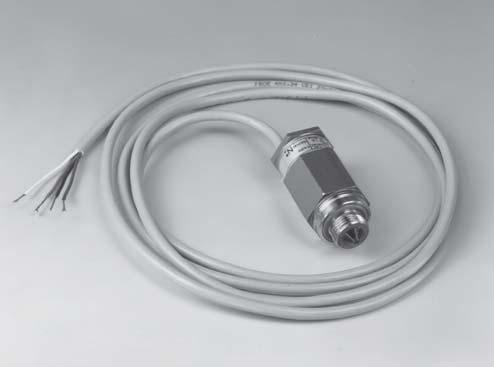
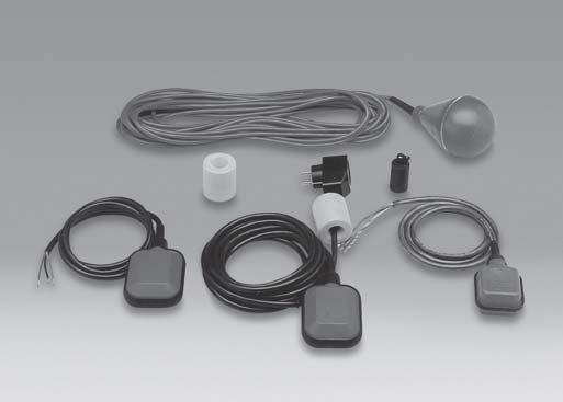
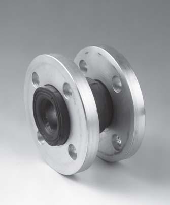
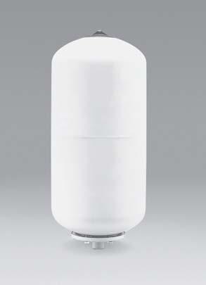
96 ACCESSORIES SORIES OPTICAL SENSORS FLOAT SWITCHES COUPLINGS CYLINDER WATER TANK NON-RETURN VALVE VALVE TECHNICAL APPENDIX 96
GRUNDFOS DATA BOOKLET. Hydro Solo-E. Complete pressure boosting systems 50/60 Hz
 GRUNDFOS DATA BOOKLET Complete pressure boosting systems 5/6 z Contents Product data Performance range 3 Operating conditions Inlet pressure Type key Product range 5 Construction 5 Installation 5 Mechanical
Multiple Pressure Booster Systems With Variable Speed Controller Type BL
 Multiple Pressure Booster Systems With Variable Speed Controller Type BL General Characteristics - Single or multistage pumps - Horizontal or vertical mounting - Total head 30m ~ 250m - Material construction:
50 Hz. GS20-GS21-GS30 Series. FIXED-SPEED PRESSURE BOOSTER SETS WITH HORIZONTAL CENTRIFUGAL ELECTRIC PUMPS FH and SH SERIES. Cod.
 Hz GS-GS1-GS3 Series FIXED-SPEED PRESSURE BOOSTER SETS WITH HORIZONTAL CENTRIFUGAL ELECTRIC PUMPS FH and SH SERIES Cod. 19191 Rev ev.b.b Ed./1 CONTENTS General introduction... Choice and selection...
Page - CONSTRUCTIONS 300 SECTIONAL VIEW DRAWING 300 SECTIONAL VIEW TABLE 301 ITEM QUANTITY FOR MODEL 302
 CONTENTS. Page - SPECIFICATIONS 200 SPECIFICATION 200 SELECTION CHART PFC 201 SELECTION CHART 202 TYPE KEY AND CURVE SPECIFICATIONS 203 PERFORMANCE CURVE 2 204 PERFORMANCE CURVE 3 205 PERFORMANCE CURVE
Installation, Operation and Maintenance Instructions for Electronically Controlled Pressurisation Units
 Installation, Operation and Maintenance Instructions for Electronically Controlled Pressurisation Units Models: EPS Single Pump EPT Twin Pump EPS-HP EPT-HP Single Pump High Pressure Twin Pump High Pressure
KIT. Small Automatic Water Boosters KIT MODELS
 KIT Small Automatic Water Boosters The electronic controller KIT orders the automatic start and stop of the water pump when opening or closing any tap or valve in the installation. There are four main
On-Off switch. Selectable manual control for commissioning. Remote start input for control via an irrigation controller, or external sensor.
 SPEEDMAN VARIABLE SPEED PUMP SET VARIABLE SPEED PUMP SET PRODUCT DESCRIPTION Variable speed / constant pressure system consisting of a Davey VM vertical multistage pump with Speedman controller, VSD unit,
APPLICATIONS. Pumping of clean, non-muddy liquids in the housing, agricultural and industrial sectors.
 OPERATING RANGES Flow rates of up to: 3 m 3 /h Manometric heads of up to: Max. delivery pressure: Max. intake pressure: Temperature range: 35 9 m CL 1 bar bar - 15 to +11 C* Max. ambient temperature: +
Hydro Dome GRUNDFOS INSTRUCTIONS
 GRUNDFOS INSTRUCTIONS Hydro Dome Installation and operating instructions Montage- und Betriebsanleitung Notice d installation et d entretien Istruzioni di installazione e funzionamento Instrucciones de
50Hz. water solutions. O SerieS DGO DRO
 Hz water solutions O SerieS DGO DRO D a t a b o o k l e t EN water solutions O SerieS DGO DRO Hz D a t a b o o k l e t O SERIES O Series General characteristics AISI stainless steel lifting and carrying
GS20-GS21-GS30 Series
 GS-GS1-GS3 Series Fixed-speed pressure booster sets with Horizontal Centrifugal electric pumps FH and SH series Hz WEB 1-1 CONTENTS General introduction... Choice and selection... 13 GS.../FH Series...13
Aquavar SOLO 2 Frequently Asked Questions
 Aquavar SOLO 2 Frequently Asked Questions How do I size the Aquavar SOLO 2 for the appropriate pump/motor combination? Can I use a 208 Volt motor? Can I run the Aquavar SOLO 2 up to 80HZ? What are the
CALEFFI. Ball zone valves. series /03 GB
 all zone valves series cert. n ISO / Function Zone valves are used to automatically shut-off the flow of carrier fluid distributed to a system. Specifically: -In central heating systems, they support the
Locator Locator-D-Lux Air-Saver G1 Air-Saver G2
 170663_air_saving_products 17-02-2011 16:42 Pagina 1 Locator Locator-D-Lux Air-Saver G1 Air-Saver G2 AIR SAVING PRODUCTS 170663_air_saving_products 17-02-2011 16:42 Pagina 2 170663_air_saving_products
COMPACT Booster Sets Data Book 50Hz
 Japanese Technology since 1912 COMPACT Booster Sets Data Book 50Hz 50Hz CONTENTS INDEX GP-GPE Page CONTENTS INDEX 2 DEFINITION AND USE OF PRESSURISATION UNITS 101 TYPICAL APPLICATIONS 101 PRINCIPLE OF
Euroswim Swimming pool pumps. 11/2010 Copyright of DWT GROUP 1
 Euroswim Swimming pool pumps 1 SWIMMING POOL PUMPS What EUROSWIM is an horizontal self-priming centrifugal electropump suitable for: Domestic swimming pools Residential swimming pools Agricoltural, industrial
SonoMeter 30 Energy Meters
 Data Sheet SonoMeter 30 Energy Meters Description The Danfoss SonoMeter 30 is a range of ultrasonic, compact energy meters intended for measuring energy consumption in heating and cooling applications
Self-priming makes priming unnecessary Exhausts the air inside the suction pipe to suck up liquid. Air operated type.
 Process Pump Series 3/5 Automatically Operated Type (Internal Switching Type)/Air Operated Type (External Switching Type) High abrasion resistance and low particle generation o sliding parts in wetted
ECONORESS ELECTRONIC EPS & EPT - ENHANCED PRESSURISATION SET INSTALLATION OPERATION & MAINTENANCE DOCUMENTATION
 ECONORESS ELECTRONIC EPS & EPT - ENHANCED PRESSURISATION SET INSTALLATION OPERATION & MAINTENANCE DOCUMENTATION OCT2010 STOKVIS ENERGY SYSTEMS 96R WALTON ROAD EAST MOLESEY SURREY KT8 0DL TEL: 020 87833050
DM01. Please visit our website: Battery Powered Precision Digital Gauge. Stainless Steel Sensor. class 0.05
 DM0 Battery Powered Stainless Steel Sensor class 0.05 Nominal pressure from 0 00 mbar up to 0... 00 bar Special characteristics modular sensor concept data logger graphic display stainless steel housing
SPECIFICATIONS ATTENTION
 VPS 504 S06 Installation Manual - P/N 80122 - Ed. 01/09 VPS 504 S06 and S05 Valve Proving System Installation Instructions VPS 1 6 Gases Natural gas, air and other inert gases. NOT suitable for butane
ETd 04. Battery Powered Precision Digital Gauge. Stainless Steel Sensor. Type: ETd 04. class 0.05
 Battery Powered Stainless Steel Sensor class 0.05 Nominal pressure from 0 100 mbar up to 0... 400 bar Special characteristics modular sensor concept data logger graphic display stainless steel housing
Submersible Electric Pumps for drainage of clean and slightly dirty water DIWA Series
 Submersible Electric Pumps for drainage of clean and slightly dirty water DIWA Series Submersible pumps for clean and slightly dirty water manufactured in AISI 304 stainless steel. Head up to 20 metres,
Process Pump Automatically Operated Type (Internal Switching Type) Air Operated Type (External Switching Type) How to Order
 Air Operated Type (External Switching Type) How to Order") Process Pump /5 Series Automatically Operated Type (Internal Switching Type)/Air Operated Type (External Switching Type) High abrasion resistance and low particle generation o sliding parts in wetted areas.
Process Pump /5 Series Automatically Operated Type (Internal Switching Type)/Air Operated Type (External Switching Type) High abrasion resistance and low particle generation o sliding parts in wetted areas.
BUBBLER CONTROL SYSTEM
 BUBBLER CONTROL SYSTEM Description: The HDBCS is a fully automatic bubbler system, which does liquid level measurements in water and wastewater applications. It is a dual air compressor system with, air
KSB Delta Compact Type Series Booklet
 Pressure Booster System KSB Delta Compact Type Series Booklet Legal information/copyright Type Series Booklet KSB Delta Compact All rights reserved. The contents provided herein must neither be distributed,
SINGLE VALVE WITH LOW-FLOW BYPASS
 CONTROL VALVES Pressure Reducing Valve Sizing Guide Sizing pilot operated reducing valves is not a complicated process. It starts with determining requirements and following these guidelines in valve size
Tightness controls TC 1 3 and TC 4
 Tightness controls TC 1 3 and TC 4 Test of both safety valves Short test period thanks to logical decision-making in the program sequence Adjustable test period which can be adapted to different systems
System Pressure Manager Standard & System Pressure Manager Plus
 System Pressure Manager Standard & System Pressure Manager Plus Installation, Commissioning & Servicing Instructions Note: THESE INSTRUCTIONS MUST BE READ AND UNDERSTOOD BEFORE INSTALLING, COMMISSIONING,
DM01. Battery Powered Precision Digital Gauge. Stainless Steel Sensor. class 0.05
 Battery Powered Stainless Steel Sensor class 0.05 Nominal pressure from 0 00 mbar up to 0... 00 bar Special characteristics modular sensor concept data logger graphic display stainless steel housing Ø
Measurement of Low GAS & Liquid Flows
 Measurement of Low GAS & Liquid Flows The Measurement Measurement with a float in a tapered borosilicate glass tube. Series 2100 with a 100 mm flow tube Series 2150 with a 150 mm flow tube Series 2300
KSB Delta Compact Type Series Booklet
 Pressure Booster System KSB Delta Compact Type Series Booklet Legal information/copyright Type Series Booklet KSB Delta Compact All rights reserved. The contents provided herein must neither be distributed,
Proportional pressure regulators VPPE
 Proportional pressure regulators VPPE Proportional pressure regulators VPPE Product range overview Function Version Pneumatic connection Proportional pressure regulator Nominal size for pressurisation/
Pressure independent control valve (PICV) FLOWMATIC
 FLOWMATIC") Pressure independent control valve (PICV) FLOWMATIC 145 series FM 21654 003 01262/19 GB replaces dp 01262/17 GB Function The pressure independent control valve is a device composed of an automatic flow
Pressure independent control valve (PICV) FLOWMATIC 145 series FM 21654 003 01262/19 GB replaces dp 01262/17 GB Function The pressure independent control valve is a device composed of an automatic flow
Axial piston pumps type PVC
 www.atos.com Table TA16-1/E Axial piston pumps type PV variable displacement, by a full line of mechanical controls PV are variable displacement axial piston pumps for medium pressure operation, low noise
Axial piston pumps type PVC
 www.atos.com Table TA16SK-1/E Axial piston pumps type PV variable displacement, by a full line of mechanical controls PV are variable displacement axial piston pumps for medium pressure operation, low
Pressure Measurement Single-range transmitters for general applications
 Siemens A 207 Overview Application The SITRANS P Compact pressure transmitter is designed for the special requirements of the food, pharmaceutical and biotechnology industries. The use of high-grade materials
Pneumatic high-pressure controller Model CPC7000
 Calibration technology Pneumatic high-pressure controller Model CPC7000 WIKA data sheet CT 27.63 Applications Healthcare and avionics industry Industry (laboratory, workshop and production) Transmitter
SIHI LPH-X - Liquid Ring Compressors
 - Liquid Ring Compressors LPH 50523 LPH 60527 Pressure range: Suction volume range: 0.2 to 1.5 bar 260 to 780 m³/h CONSTRUCTION Sterling SIHI liquid ring compressors are displacement compressors with a
IDL01. Battery Powered Precision Digital Gauge for Leak Testing. Stainless Steel Sensor. class 0.05
 IDL0 Battery Powered Precision Digital Gauge for Leak Testing Stainless Steel Sensor class 0.05 Nominal pressure from 0 00 mbar up to 0... 00 bar Special characteristics modular sensor concept data logger
Pneumatic high-pressure controller Model CPC7000
 Calibration technology Pneumatic high-pressure controller Model CPC7000 WIKA data sheet CT 27.63 Applications Automotive and avionics industry Industry (laboratory, workshop and production) Transmitter
Inverse Proportional Pressure-Relief Cart., Size 2 4
 Inverse Proportional Pressure-Relief Cart., Size Q max = l/min, p max = 35 bar Direct acting, electrically operated Description Compact construction for cavity type AL 3/-6 UNF Operated by a proportional
1. PARTS INTRODUCTION ELECTRICAL NOTES INSTALLATION 5/6. 5. START UP 6/7. 6. MAINTENANCE 7/8/9. 7. PRESSURE SWITCH ADJUSTMENTS 9/10.
 CONTENTS 1. PARTS 3. 2. INTRODUCTION 4. 3. ELECTRICAL NOTES 5. 4. INSTALLATION 5/6. 5. START UP 6/7. 6. MAINTENANCE 7/8/9. 7. PRESSURE SWITCH ADJUSTMENTS 9/10. 8. ELECTRICAL CONNECTIONS 10/11. 9. SPECIFICATIONS
C-Flow Coriolis Mass Flow Meters
 Coriolis Mass Flow Meters Ready for Take Off The New Compact C-Flow Küppers Elektromechanik GmbH The C-Flow The C-Flow Coriolis Mass Meters consist of two components: KCE Transmitter KCM Transducer 2 KEM
Proportional Pressure-Relief Cartridge Valve, Size 2...4
 Proportional Pressure-Relief Cartridge Valve, Size... Q max = l/min, p max = 3 bar Direct acting, electrically operated 1 Description proportional pressure-relief valves are direct acting screw-in cartridges
SITRANS P measuring instruments for pressure
 SITRANS P measuring instruments for pressure Z series for gage pressure Siemens AG 008 Overview Design The main components of the pressure transmitter are: Brass housing with silicon measuring cell and
High Pressure Breathing Air Compressors
 High Pressure Breathing Air Compressors [ Full variety for different applications] MSA offers a comprehensive range of high pressure breathing air compressors for both the firefighting and diving market,
Monitoring device NTS 30
 P R O D U C T I N F O R M A T I O N Electronic level- and temperature monitoring device Monitoring device NTS 30 Contents Description Description... 2 Operating... 3 Design and electrical data... 4 Circuit
Pneumatic spool valve islands
 Pneumatic spool valve islands P7.GB.R MEGA SPOOL VALVE ISLANDS MEGA pneumatic spool valve islands offer maximum performance along with flexibility, easy installation and simple operation. Due to their
COMPRESSED AIR SAVING PRODUCTS INDEX. Useful information AIR-SAVER G1 AIR-SAVER G2 LOCATOR. Condensate Management Specialist
 INDEX Useful information AIR-SAVER G1 AIR-SAVER G2 LOCATOR COMPRESSED AIR SAVING PRODUCTS Condensate Management Specialist Information provided herewith is believed to be accurate and reliable. However,
Proportional Pressure-Relief Cartridge Valve, Size 2...4
 Proportional Pressure-Relief Cartridge Valve, Size... Q max = l/min (6 gpm), p max = bar (58 psi) Direct acting, electrically operated Description proportional pressure-relief valves are direct acting
Air Operated Hydraulic Pumping Systems to 50,000 psi
 High Pressure Equipment Air Operated Hydraulic Pumping Systems to 50,000 psi PS-10: 10,000 psi PS-20: 20,000 psi PS-30: 30,000 psi PS-40: 40,000 psi PS-50: 50,000 psi PS-90: 90,000 psi High Pressure air
Electropneumatic Positioner and Pneumatic Positioner Type 3760 JIS
 Electropneumatic Positioner and Pneumatic Positioner Type 3760 Application Single-acting positioners for direct attachment to pneumatic control valves. Supplied with an electric input signal of 4 to 20
Inverse Proportional Pressure-Relief Cart., Size 2 4
 Inverse Proportional Pressure-Relief Cart., Size Q max = l/min, p max = 5 bar Direct acting, electrically operated 1 Description inverse proportional pressure-relief valves are direct acting screw-in cartridges
Liquid ring vacuum pumps in compact design
 Liquid ring vacuum pumps in compact design LEM 25, LEM 5 Pressure range: Suction volume flow: 33 to 113 mbar 4 to 6 m³/h CONSTRUCTION SIHI liquid ring vacuum pumps are displacement pumps of uncomplicated
Pressure Automated Calibration Equipment
 GE Measurement & control Pressure Automated Calibration Equipment Safety Instructions and User Guide - K0447 PACE5000 PACE6000 K0447 Issue No. 9 1 10 1 PACE5000 1 2 3 4 5 PACE6000 2 6 7 8 3 4 5 6 7 8 9
Types and approvals. Page 1/6. Data Sheet
 Page 1/6 Panel-mounting Thermostats EM Series as: Protection temperature monitor STW (STB) Protection temperature limiter STB tested to DIN 3440 and Pressure Equipment Directive 97/23/EC Brief description
![[Instruments for vacuum measurement, checking and adjustment] 3](/thumbs/94/121874202.jpg "[Instruments for vacuum measurement, checking and adjustment] 3")
BUBBLER CONTROL SYSTEM
 BUBBLER CONTROL SYSTEM Description: The LDBCS is a fully automatic bubbler system, which does liquid level measurements in water and wastewater applications. It is a dual air compressor system with, air
VPPL VARIABLE DISPLACEMENT AXIAL-PISTON PUMPS FOR INTERMEDIATE PRESSURE SERIES 10
 / ED VPPL VARIABLE DISPLACEMENT AXIAL-PISTON PUMPS FOR INTERMEDIATE PRESSURE SERIES OPERATING PRINCIPLE The VPPL are variable displacement axial-piston pumps with variable swash plate, suitable for applications
2 Overview. SITRANS P measuring instruments for pressure. Transmitters for gage and absolute pressure. Z series for gage pressure
 Z series for gage pressure Overview Design The main components of the pressure transmitter are: Brass housing with silicon measuring cell and electronics plate Process connection Electrical connection
Pressure Transmitters 36 F-27839
 Pressure Transmitters 36 F-27839 SPD310/SPD360 Air Differential schneider-electric.com 37 SPD310/SPD360 SPD310/SPD360 differential pressure transmitters are intended for use in air handling systems for
Installation, Operation and Maintenance Instructions for Electronically Controlled Pressurisation Units Digital Range
 Installation, Operation and Maintenance Instructions for Electronically Controlled Pressurisation Units Digital Range Models: DS 126 Single Pump / Single System DT 126 Twin Pump / Single System DS 160
Pressure transmitters EMP 2
 Data sheet Pressure transmitters EMP 2 The high accuracy pressure transmitter EMP 2 is designed for monitoring and control in marine and industial applications and offers a reliable pressure measurement,
Axial piston pumps type PVPY-C (-R, -L) variable displacement, with mechanical controls obsolete components - availability on request
 variable displacement, with mechanical controls obsolete components - availability on request") www.atos.com Table TA60obs/E Axial piston pumps type PVPY- (-R, -) variable displacement, with mechanical controls obsolete components - availability on request PVPY are variable displacement axial piston
www.atos.com Table TA60obs/E Axial piston pumps type PVPY- (-R, -) variable displacement, with mechanical controls obsolete components - availability on request PVPY are variable displacement axial piston
Liquid ring vacuum pumps in compact design
 Liquid ring vacuum pumps in compact design, Pressure range: Suction volume flow: 33 to 113 mbar 3 to 58 m³/h CONSTRUCTION TYPE SIHI liquid ring vacuum pumps are displacement pumps of uncomplicated and
Inverse Prop. Pressure-Relief Cart., Size 2 4
 Inverse Prop. Pressure-Relief Cart., Size Q max = l/min (6 gpm), p max = bar (58 psi) Direct acting, electrically operated Description inverse proportional pressure-relief valves are direct acting screw-in
ASX 176 Axial Pressure regulator
 ASX 176 Axial Pressure regulator ASX 176 Classification and Area of Application ASX 176 is a downstream pressure regulator, pilot controlled, for medium and high pressure applications. It is particularly
Measuring range Δp (span = 100%) Pa
 Pa") 4.4/ RLE 5: Volume-flow controller, continuous How energy efficiency is improved Enables demand-led volume flow control for the optimisation of energy consumption in ventilation systems. Areas of application
4.4/ RLE 5: Volume-flow controller, continuous How energy efficiency is improved Enables demand-led volume flow control for the optimisation of energy consumption in ventilation systems. Areas of application
Gas density monitor With integrated transmitter Model GDM-100-TI
 SF 6 gas solutions Gas density monitor With integrated transmitter Model GDM-100-TI grid Products WIKA data sheet SP 60.05 for further approvals see page 5 Applications Gas density monitoring of closed
OPERATING INSTRUCTIONS MANUAL FOR QACV PNEUMATIC DOSING PUMP
 This operating instructions contains safety information that if ignored can endanger life or result in serious injury. They are indicated by this icon. Use of this pump with radioactive chemicals is forbidden!
Inverse Proportional Pressure-Relief Cartridge, Size 10
 Inverse Proportional Pressure-Relief Cartridge, Size 1 Q max = 12 l/min, p max = 3 bar Seated pilot, spool-type main stage, damped design 1 Description inverse-proportional pressure-relief valves are size
Operating instructions Safety Rope Emergency Stop Switches ZB0052 / ZB0053 ZB0072 / ZB0073
 Operating instructions Safety Rope Emergency Stop Switches UK ZB0052 / ZB0053 ZB0072 / ZB0073 7390878 / 02 03 / 2011 Contents 1 Safety instructions...3 2 Installation / set-up...4 2.1 Applications...4
Process Pump. PAF3000 Series/PAF5000 Series
 Process Pump PAF3 Series/PAF Series RoHS The excellent corrosion resistance is achieved due to the new PFA wetted material construction! PPS/PFA dual construction, withstand pressure and heat cycle performance
TECHNICAL DESCRIPTION
 TECHNICAL DESCRIPTION Exhaust Hose Reel ser. 865, electric motor driven No. 981118101 Description Limit switches, for hose coiling and uncoiling integrated in drive unit. Motor turns drum via a planetary
Type 4708 Supply Pressure Regulator
 Type 478 Pressure Regulator Application pressure regulators used to provide pneumatic measuring and control equipment with a constant air supply Set point ranges. to. bar ( to 4 psi). to bar (8 to 9 psi)
RP series Rotor Pumps
 ontact etails RP series Rotor Pumps Nomenclature Features Low noise Substantial reduction of the operation noise, by to db (comparison with aikin products), and improved sound quality are achieved by adopting
Series MX pressure regulators 3/
 CATALOGUE > Release 8.8 > Series MX regulators Series MX pressure regulators MX2 ports: G/8, G1/2, G/4 - MX ports: G/4, G1 Manifold ports: G1/2 (MX2 only) Modular - Available with built-in pressure gauges
OPTIBAR P 1010 C Technical Datasheet
 Technical Datasheet Pressure transmitter with recessed diaphragm for general applications Wide variety thanks to modular design Measuring ranges up to 250 bar / 3750 psi High overload and temperature stability
Type 4708 Supply Pressure Regulator
 Type 478 Pressure Regulator Application pressure regulator used to provide pneumatic measuring and control equipment with a constant air supply Set point ranges. to.6 bar ( to 4 psi) or. to 6 bar (8 to
TECHNICAL DATA MAINTENANCE AIR COMPRESSOR MODEL G-1
 Dry 131h 1. DESCRIPTION The Viking Model G-1 Maintenance Air Compressor is an electric motor-driven, aircooled, single-stage, oil-less compressor. The unit is equipped with a check valve and provides a
SPOOL VALVES. pilot operated single/dual solenoid (mono/bistable function) ISO mm - pad mounting body M12 connection
 ISO mm - pad mounting body M12 connection") SPOOL VALVES pilot operated single/dual solenoid (mono/bistable function) ISO 07-8 mm - pad mounting body M connection x/ - / - / Series 0 ISO 07- (8 mm) FEATURES M connection on top of valve: reduces
SPOOL VALVES pilot operated single/dual solenoid (mono/bistable function) ISO 07-8 mm - pad mounting body M connection x/ - / - / Series 0 ISO 07- (8 mm) FEATURES M connection on top of valve: reduces
BOSS PULISCI PROVA IMPIANTI MEDIA
 BOSS PULISCI PROVA IMPIANTI MEDIA Pump for power flushing operations and removal of impurities, suitable for hydraulic, solar, floor systems and for cooling circuits of medium size. Suitable for buildings,
Torque Tube TB300 Digital Transmitters
 Page 1 of 7 7E.300-E Issue 4-2009 Description Series TB300 torque tube liquid level instruments utilize the buoyancy exerted on a displacer when immersed in a liquid. The buoyancy on the displacer is proportional
Compact differential pressure switch Flameproof enclosure Ex d Models DE, DEC
 Mechatronic pressure measurement Compact differential pressure switch Flameproof enclosure Ex d Models DE, DEC WIKA data sheet PV 35.41 Process Compact Series Applications Differential pressure monitoring
Expansion Vessels for Potable Installations
 4. Expansion Vessels for Potable Installations Domestic installations lose millions of litres of potable water due to expansion water leaking from the vent and expansion pipe. Flamco s Airfix diaphragm
MOYNO FLUID DETECTION CONTROL SERVICE MANUAL. Section: ACCESSORIES. Page: 1 of 8 Date: May 1, 1998 GENERAL
 MOYNO Section: ACCESSORIES Page: 1 of 8 Date: May 1, 1998 SERVICE MANUAL FLUID DETECTION CONTROL GENERAL The Moyno Fluid Detection Control prevents unnecessary loss of production time or repair costs to
2/2-Way Solenoid Control Valve
 2/2-Way Solenoid Control Valve Excellent range (1:200) Very good response Compact valve design Orifice sizes 0.05... 2.0 mm Port connection 1/8 or sub-base Type 2871 can be combined with Type 8605 Digital
AIR SAVING PRODUCTS ADDING VALUE AIR-SAVER LOCATOR LOCATOR-EV
 AIR SAVING PRODUCTS AIR-SAVER LOCATOR LOCATOR-EV ADDING VALUE REL LIABLE COMPRESSED AIR CONDENSATE MANAGEMENT AND ENERGY SAVING PRODUCTS Air saving products INDEX Chapter Content 1 Introduction to compressed
Booster Regulator/Air Tank
 Booster Regulator/Air Tank Increase factory air pressure by up to 4 times! Air-only operation requires no power supply, reduces heat generation, and Boost pressure allows easy installation. NEW Renewed
The M-Series Eletta Flow Meter High accuracy DP Flow Meter with multiple functions
 The M-Series Eletta Flow Meter High accuracy DP Flow Meter with multiple functions Flow Meter with multiple functions for gases and liquids M3 The M-series Flow Meter, with its versatile and user-friendly
Electronic Single and Twin Pump System Pressure Managers
 Electronic Single and Twin Pump System Pressure Managers Installation, Commissioning & Servicing Instructions Note: THESE INSTRUCTIONS MUST BE READ AND UNDERSTOOD BEFORE INSTALLING, COMMISSIONING, OPERATING
Prop. 3-Way Pressure-Reducing Cart., Size 5 / SAE 08
 Prop. -Way Pressure-Reducing Cart., Size / SAE 8 Q max = 1 l/min (4 gpm), p max = bar (6 psi) Direct acting, electrically operated 1 Description proportional -way pressure-reducing cartridges are size
Design Features. General Description
 Model thermal Mass Flow Controllers are designed to indicate and control set flow rates of gases. The combines the characteristics and accuracy of conventional mass flow devices into a unique compact design
Simple Set Max. Pressure Independent Control Valves 2 Way 2-1/ /09/18
 The Bray Simple Set Max is a flanged pressure independent control (PIC) valve designed for a wide variety of hot water and chilled water control applications. The SSM Series combines high rangeability
Level switches Series LD Vibrating fork level switch for liquids and solids
 Level switches Series LD Vibrating fork level switch for liquids and solids Robust and compact Suitable for liquids (model LD61) and solids (model LD60) No moving parts, low maintenance Corrosion resistant
Glass tube flowmeters Series 2000
 Glass tube flowmeters Series 2000 Variable area flowmeter for low flows of liquids and gases Short mounting length and compact construction, especially indicated for control panels Easy installation. No
Norval Pressure regulator
 Norval Pressure regulator NORVAL Classification and Field of Application The NORVAL is a downstream pressure regulator, self actuated, spring loaded for medium and low pressure applications. It is suitable
Electronic relative and differential pressure switch type 616
 Electronic relative and differential pressure switch type 616 Pressure range 0... 0.1 25 bar The switching points of the pressure switch type 616 can be potentiometer adjusted by the customer, or set in
Liquid ring vacuum pumps single-stage
 Liquid ring vacuum pumps single-stage LPH 40106, LPH 40411, LPH 40516 Pressure range: Suction volume flow: 150 to 1013 mbar 50 to 270 m³/h CONSTRUCTION TYPE Sterling SIHI liquid ring vacuum pumps are displacement