DANLOAD OPERATIONS MANUAL
|
|
|
- Elfrieda Laureen Patterson
- 5 years ago
- Views:
Transcription
1 DANLOAD OPERATIONS MANUAL DANIEL INDUSTRIES, INC. DANLOAD OPERATIONS REFERENCE MANUAL (including DANBLEND OPERATIONS) Part Number: Revision B June 1996
2
3 DANLOAD DANIEL INDUSTRIES, INC. DANBLEND OPERATIONS REFERENCE MANUAL (including DANBLEND OPERATIONS) NOTICE DANIEL INDUSTRIES, INC. AND DANIEL MEASUREMENT AND CONTROL ("DANIEL") SHALL NOT BE LIABLE FOR TECHNICAL OR EDITORIAL ERRORS IN THIS MANUAL OR OMISSIONS FROM THIS MANUAL. DANIEL MAKES NO WARRANTIES, EXPRESS OR IMPLIED, INCLUDING THE IMPLIED WARRANTIES OF MERCHANTABILITY AND FITNESS FOR A PARTICULAR PURPOSE WITH RESPECT TO THIS MANUAL AND, IN NO EVENT, SHALL DANIEL BE LIABLE FOR ANY SPECIAL OR CONSEQUENTIAL DAMAGES INCLUDING, BUT NOT LIMITED TO, LOSS OF PRODUCTION, LOSS OF PROFITS, ETC. PRODUCT NAMES USED HEREIN ARE FOR MANUFACTURER OR SUPPLIER IDENTIFICATION ONLY AND MAY BE TRADEMARKS/REGISTERED TRADEMARKS OF THESE COMPANIES. COPYRIGHT 1996 BY DANIEL MEASUREMENT AND CONTROL HOUSTON, TEXAS, U.S.A. All rights reserved. No part of this work may be reproduced or copied in any form or by any means - graphic, electronic or mechanical - without first receiving the written permission of Daniel Measurement and Control, Houston, Texas, U.S.A. PREFACE i
4 DANLOAD WARRANTY Daniel Measurement and Control ("Daniel") warrants all equipment manufactured by it to be free from defects in workmanship and material, provided that such equipment was properly selected for the service intended, properly installed, and not misused. Equipment which is returned, transportation prepaid to Daniel within twelve (12) months of the date of shipment (eighteen (18) months from date of shipment for destinations outside of the United States), which is found after inspection by Daniel to be defective in workmanship or material, will be repaired or replaced at Daniel s sole option, free of charge, and return-shipped at lowest cost transportation. All transportation charges and export fees will be billed to the customer. Warranties on devices purchased from third party manufacturers not bearing a Daniel label shall have the warranty provided by the third party manufacturer. Extended warranty - Models 2470, 2480 and 2500 are warranted for a maximum of twenty-four (24) months. The Danalyzer valves are warranted for the life of the instrument and the columns for five years. The warranties specified herein are in lieu of any and all other warranties, express or implied, including any warranty of merchantability or fitness for a particular purpose. Daniel shall be liable only for loss or damage directly caused by its sole negligence. Daniel s liability for any loss or damage arising out of, connected with, or resulting from any breach hereof shall in no case exceed the price allocable to the equipment or unit thereof which gives rise to the claim. Daniel s liability shall terminate one year after the delivery of the equipment except for overseas deliveries and extended warranty products as noted above. In no event, whether as a result of breach of warranty or alleged negligence, shall Daniel be liable for special or consequential damages, including, but not limited to, loss of profits or revenue; loss of equipment or any associated equipment; cost of capital; cost of substitute equipment, facilities or services; downtime costs; or claims of customers of the purchaser for such damages. ii PREFACE
5 DANLOAD TABLE OF CONTENTS 1.0 INTRODUCTION Description of Operation PHYSICAL LAYOUT OF SYSTEM DANMASTER Layout DANTROL Layout INITIAL POWER UP OF SYSTEM CALIBRATION: GENERAL INFORMATION Operational Set Up Select Language (Option #1) Communications Parameters Host/Comms (Option #2) DART Data Rates (Option #3) DANMASTER Address (Option #4) Temperature (Option #5) Dual Pulse (Option #6) Additives (Option #7) Preset Parameters Maximum Preset (Option #8) Minimum Preset (Option #9)...25 _ TABLE OF CONTENTS iii
6 DANLOAD 4.8 Alarm Parameters Low Flow Alarm (Option #15) Time to Min Flow Rate (Option #17) No Flow Time Out (Option #18) Unauthorized Flow Limit (Option #19) Pump Delay Parameters Line Pack Delay (Option #20) Pump Stop Delay (Option #21) Low Flow Parameters Low Meter Factor (Option #30) Low Flow Rate (Option #31) Low Flow Start Up (Option #32) Low Flow Shutdown (Option #33) Run Low Flow Test (Option #34) Medium Flow Parameters Medium Meter Factor (Option #35) Medium Flow Rate (Option #36) Run Medium Flow Test (Option #37) High Flow Parameters High Meter Factor (Option #38)...33 _ iv TABLEOFCONTENTS
7 DANLOAD High Flow Rate (Option #39) Run High Flow Test (Option #40) Status Points Status Pt. 1 - Type (Option #70) Status Pt. 1 - Invert (Option #71) Status Pt. 2 - Type (Option #72) Status Pt. 2 - Invert (Option #73) Status Pt. 3 - Type (Option #74) Status Pt. 3 - Invert (Option #75) Status Pt. 4 - Type (Option #76) Status Pt. 4 - Invert (Option #77) Alternative Calibration Sequencing Options Initiate Complete Calibration Sequence Resume Sequencing (Option #95) EXITING SET UP/CALIBRATION CALIBRATION OVERVIEW Calibration of the Meter GENERAL USER PROCEDURES...49 _ TABLE OF CONTENTS v
8 DANLOAD 8.0 PRODUCT SECURITY Primary Alarms Secondary Alarms GENERAL HARDWARE SET UP TROUBLESHOOTING GUIDE Overview DANMASTER Faults Preset Alarms Valve or System Faults CALIBRATION: AN IN DEPTH ANALYSIS Scope General Information Manual Calculations Uncertainties...89 APPENDIX A - DIAGRAMS...93 APPENDIX B - MISCELLANEOUS LITERATURE...95 Spare Parts Listing...96 APPENDIX C - THE DANBLEND...99 _ vi TABLEOFCONTENTS
9 DANLOAD 1.0 INTRODUCTION The purpose of this manual is to familiarize users with the functions of the DANLOAD system s hardware and software, as well as to provide the terminal staff with a basic understanding of troubleshooting and meter calibration. Each section is discussed in its entirety, with a general overview of that part of the system preceding each discussion. Operations staff should review this manual before attempting to operate, troubleshoot, or calibrate any of its equipment. In addition, this manual is written with the assumption that the operator is someone who is knowledgeable in the field of terminal operations, specifically load rack applications. This manual should be kept for quick reference when using DANLOAD equipment. Furthermore, Appendix C of this manual contains information on the DANBLEND system s hardware and software, which should be used in conjunction with the DANLOAD Operations Manual. The DANLOAD system firmware, including any related documentation is furnished to the purchaser under license for use on the system for which, or in connection with which it is supplied. The purchaser may reproduce or modify any such documentation only for use on that system, and only provided all reproductions and modifications carried out by the purchaser or their agents have specifically been approved by Daniel Automation Division, Daniel Industries, Inc.. The purchaser may not make the firmware, hardware, and related documentation or the contents thereof available to third parties without the written approval of Daniel Automation Division, Daniel Industries, Incorporated. The DANLOAD is an island based batch controller and is comprised of the following components: 1) DANMASTER 2) Explosion Proof Unit (EPU) 3) DANTROL 4) L.R. Turbine Meter 5) DANFLO Control Valve The DANMASTER is the central control unit and houses the Meter Control Units (MCU), Central Processing Unit (CPU), Program Storage (ROM), Power Supply Unit (PSU), and I.S. barriers. The DANMASTER and EPU are both housed in Nema 7 enclosures. The DANMASTER is strictly a low voltage D.C. device. All A.C. power in the system is terminated in the EPU. The EPU houses the A.C. to D.C. power supply and thirty-two solid state relays for control of circuits such as pumps, valves, and additive injectors. SECTION 1 1
10 DANLOAD The DANTROL unit is the operator interface to the system. The DANTROL has three Liquid Crystal Displays (LCDs); two are six-character numeric displays for the preset and delivered quantities; the third is a two line, sixteen-character per line, alpha-numeric display. The DANTROL also utilizes a keypad for driver input of data. The DANTROL is a U.L. rated, intrinsically safe device. Up to six DANTROL units can be interfaced to one DANMASTER/EPU set. The DANLOAD system can perform safe, accurate batch loading in a stand-alone environment. However, this may also be dependent on the degree with which the system is interfaced with the terminal automation system used at the terminal. This degree of independent operation is determined by the end user. The following topics cover the design features of the DANLOAD. Each feature is described on a per riser basis: 1) Capabilities A) Three K-factor inputs, for low, medium, and high flow rates, designed to linearize the meter accuracy curve. B) The DANLOAD provides low flow start-up and shutdown. The system can also control an intermediate flow rate if the maximum rate is unattainable due to under pumped conditions. This provides for operation at known points along the meter curve. C) The DANLOAD provides two levels of system security, primary and secondary. Secondary alarms provide local indication of the alarm on the alpha-numeric display and pulse an alarm contact at one second intervals. The secondary alarms are based on the four status point inputs and can be cleared simply by correcting the status point failure. 2 SECTION 1
11 DANLOAD Primary alarms also provide local indication of the problem on the display but holds the alarm contact indefinitely. The primary alarms must be reset by means of a key. Primary alarms are: no flow detected, flow rate too slow, unauthorized flow, dual pulse failure, temperature probe failure, and unable to close valve. D) The system is easily programmed via the prompting display and keypad. Parameters such as minimum preset amount, maximum preset amount, minimum flow rate, and minimum flow rate time out period are user programmable along with K-factors, flow rates and some time durations. The DANLOAD also offers a proving routine to assist in establishing K-factors and performing meter calibration. 2) Inputs A) Four permissive inputs per DANTROL, for status input monitoring. Inputs may include DART SYSTEM permissive, scully permissive, vapor recovery, grounding system, etc. At the minimum, we suggest monitoring the scully system. B) Raw meter pulse input, either singularly or in a dual pulse security mode. 3) Outputs A) One pulse per unit open collector, for whole unit output to an automation system such as the DART SYSTEM. B) One solid-state relay pump control circuit output with programmable line pack delay and shutoff delay time periods. SECTION 1 3
12 DANLOAD C) Two solid-state relays for "digital" valve control, such as the Daniel DANFLO valve, Smith 210 or Brooks 788 Models. D) One solid-state relay for alarm indication. E) Four additive control solid state relay outputs for additive pacing. Each additive ratio is user programmable. The L.R. TURBINE METER is responsible for accurate and repeatable measurement of the product. The L.R. was specifically designed for load rack applications. The meter features a unique self-cleaning ball bearing design and a patented self-cleaning hanger. The meter body is stainless steel and utilizes aluminum internals. There is also a carbon steel model. The driving force behind the design was to offer an extremely accurate and repeatable meter at a very competitive price. The DANFLO valve performs the actual product control. The DANFLO is a spring biased, positive sealing, fail-shut valve. There are two solenoids on the DANFLO which are controlled by the DANLOAD. These two solenoids are used to control product behind the piston. The product itself is, therefore, used to actually move the piston throughout its travel. The DANLOAD system analyzes the frequency of incoming pulses from the meter, compares this to the programmed parameters and then modulates the valve in both the low, medium, and high flow rates. 4 SECTION 1
13 DANLOAD 1.1 DESCRIPTION OF OPERATION During product flow, the DANLOAD system controls the valve solenoids to achieve the preset volume and to maintain the programmed flow rates on the basis of the pulse count and the established meter K-factors. Low flow start-up and shutdown periods are monitored and controlled using the gross volume. Additionally, the DANLOAD system computes the average valve closure period at the end of each normally terminated load. The average valve closure period is used to ensure that the product flow is halted at the preset volume. The current load total and meter totalizers are continuously stored in non-volatile memory to guard against data loss in the event of a power failure. Loss of line power results in immediate shutdown of the loading operations. Pulses are counted until full internal power failure occurs. When power is restored, the final counts are accessed by the system for use. All critical calibration functions are stored in non-volatile memory so that they may be retrieved when power is restored. When the temperature option is installed, five methods of calculating the net product flow are permitted by using one of five American Petroleum Institute (API) tables. Temperature samples are only averaged into the loading temperature when product is flowing. The DANLOAD temperature sub-system produces a true weighted average for the loaded volume in that the total number of samples is divided into the sum of all the temperatures taken. Additionally, these samples are taken on a volumetric basis instead of a timed basis. Additive injection outputs, of which there are four, are controlled using the ratios entered by the operator during system setup. The ratios are the number of units of measure loaded per one output pulse delivered to the additive relay. Each additive has an individually programmable ratio. Additive control is achieved by cycling the additive s relay on a 50% duty cycle each time the adjusted volume is equal to any multiple of the additive s ratio. This calculation is performed separately for each additive installed, thus permitting different ratios for each additive relay. SECTION 1 5
14 DANLOAD The units of measure displayed are a function of the meter calibration K-factor. The meter K-factor is given as the number of pulses input into the DANLOAD system per unit of measure pumped. This factor is usually marked on the meter by the factory (typically /-.5 for a 4" system). The meter K-factor is entered as "XX.XXXX". The DANLOAD system permits meter K-factors from 1.0 to Meter factors of less than 1.0 are not permitted because there would not be sufficient pulse generation per unit of measure for the system to control valve closure properly. A meter K-factor of 10.0 or greater is recommended. Valve control is achieved by stepping the valve, open or closed, until the desired flow rate is attained. The valve position is then adjusted every one second throughout the load, if necessary, to maintain the desired flow rate of + or - 5%. If the flow rate cannot be achieved, the DANLOAD steps down to the programmed medium flow rate, if it being used. If this rate cannot be achieved, the DANLOAD "locks-in" at the flow rate which is currently being pumped (see also Sections 5.0 and 11.0 on meter calibration). This feature results in true digital valve control and in the ability to maintain a stable flow rate even during varying pressure/demand situations. Additionally the more stable the flow, the better the results of meter repeatability. Operator selectable minimum flow rate and time-out values are used to continually check the current flow rate against the set values. If the flow rate remains below the minimum value for a period greater than the time-out value, the alarm relay is enabled and an alarm condition is declared. The operator also selects the time out period that is permitted after the product is authorized before pulses must be sensed. This limits the volume of product that would be permitted to flow in the event the pulser should fail. This value is also used to check for the loss of pulses during a load. A "no flow" condition causes the alarm relay to be enabled and an alarm condition is declared. During periods when product flow is not authorized, the DANLOAD system monitors the pulser input, looking for unauthorized product flow. The operator can program a value for the allowable unauthorized flow between loads. If the unauthorized flow value is exceeded, the system enables an alarm relay and declares an alarm condition. While normal loading is in progress, the user can stop the flow of product by pressing the "C", STOP LOAD, key. The DANLOAD system then ramps the DANFLO valve back into low flow and then stops the flow by fully closing the valve. To start flow again, the user must enter a new preset value. If the volume to load is the remainder of the original preset, the quantity may be obtained from the top numeric display. 6 SECTION 1
15 DANLOAD Pressing the "D", CANCEL LOAD, key immediately closes the valve and disables the pump control relay. This may result in "line shock" if the product is flowing at a very high rate. The user must preset the unit again to restart the product flow. The "B", START LOAD, key does not restart the loading operation after either the "C", or "D", keys are pressed, without first entering a new preset value. The "A", PRESET, "C", STOP LOAD, and "D", CANCEL LOAD, keys also cancel a preset before the "B", START LOAD, key is pressed. Additionally, when no preset or loading operation is taking place, pressing the "D" key causes the display of the totalizer value on the alpha-numeric display. Pressing the "C" key displays the current probe temperature as well as the average temperature of the last load (provided a temperature board is installed and the temperature option is selected). The pump relay is enabled for an operator selectable delay period (line pack delay) before the control valve attempts to open and is held enabled for an operator selectable delay period (pump stop delay) after a normal load termination. The operator may use a dual pulse transmitter with the DANLOAD system and program the permitted difference between the two pulser inputs. If a difference greater than the selected value is achieved, the system terminates the loading process, enables the alarm relay, and declares an alarm condition. The operator determines the maximum permissible preset volume. The DANLOAD system uses this value to prevent excess preset values that are sometimes used to bypass the low flow start-up and shutdown volumes. It is recommended that this parameter be set to a value less than or equal to the maximum compartment size of authorized vehicles. The minimum permissible preset volume is also programmed by the operator. The DANLOAD system should be programmed with a large enough value to permit proper valve closure control and yet small enough to provide for load "topping off". SECTION 1 7
16 DANLOAD This page intentionally left blank. 8 SECTION 1
17 DANLOAD 2.0 PHYSICAL LAYOUT OF SYSTEM PUMP EPU ADDITIVES VALVE ALARM METER AUTOMATION SYSTEM DANMASTER STATUS POINTS DANTROL SECTION 2 9
18 DANLOAD 2.1 DANMASTER LAYOUT The general card-slot assignment for the DANMASTER is as follows: Slot 1 - Power with Communications Board Slot 2 - MCU #1 - #4 Slot 6 - CPU Board Slot7-MUC#5 Slot 8 - ROM Board Slot 9 - Temperature Board NOTE: MCU #6 may be replaced by a temperature board, if applicable. Additionally, the CPU and 64K ROM boards are not labeled due to the fact they do not plug into a connector located in the backplane. They may be inserted anywhere between MCU #1 and MCU #6. 10 SECTION 2
19 DANLOAD 2.2 DANTROL LAYOUT The physical layout of the DANTROL is as follows: P R E S E T D E L I V E R E D PRESET READY KEYPAD A B C CLR 0 ENT D NOTE: An alarm reset switch is located on the DANTROL box to clear alarms. The DANTROL calibration switch is located within the DANTROL housing on the ACU board. SECTION 2 11
20 DANLOAD This page intentionally left blank. 12 SECTION 2
21 DANLOAD 3.0 INITIAL POWER UP OF SYSTEM Install the DANLOAD system in accordance with this manual and any applicable codes. It is strongly recommended that a qualified field service representative from Daniel be present during initial power up of the system. The electrical contractor should also be present at this time. All wiring should be checked to insure a safe, reliable start-up. In the case of a conflict arising with the installation, the National Electric Code takes precedence. However, the electrical contractor should first contact Daniel Automation Division, Daniel Industries, Incorporated, for verification prior to installation. As the system is powered up, the boot loader firmware loads the DANLOAD application program and performs an internal check to ensure that the program was properly loaded from the ROM board into the CPU s random access memory. After passing this initial check, the loading application program begins execution. The loading application program first checks areas of the battery-backed RAM to make certain that the battery-backed RAM had not been altered and that it may be written to. If the batterybacked RAM cannot be written to, the program prevents the system from initializing and running. If the "power on" situation is the first "power on" encountered by the battery-backed RAM, or if the battery-backed RAM has not been initialized using this program revision level, the system notes that there is a need to initialize the values stored in the battery-backed RAM before permitting the use of the DANLOAD system. The states of the ALARM RESET switch and the CALIBRATION switch are then checked. If either switch is in a position other than the normal run position, the operator is prompted with: SWITCH OFF and/or SWITCH OFF ALARM RESET CALIBRATION These messages are displayed until the operator takes the indicated action. SECTION 3 13
22 DANLOAD After the completion of the internal software initialization and a cursory hardware check, the DANLOAD system may prompt the operator with: ALARM PENDING RESET ALARM This message indicates that when the DANLOAD system was last powered down, there was an alarm condition pending. The operator must reset the alarm before the program permits the operator to continue. This is done by turning on the ALARM RESET switch. This action should not be taken until the operator has determined that the cause of the alarm condition has been properly cleared and that the DANLOAD system may be safely operated. After the ALARM RESET has been turned on, the operator is prompted with: SWITCH OFF ALARM RESET The operator must then turn off the ALARM RESET switch. As indicated before, the DANLOAD may note that the battery-backed RAM has not been previously initialized. If this circumstance occurs, the system prompts the following: CHECK TOTALIZERS This indicates that the operator must press the "D", CANCEL LOAD, key which also serves as the CHECK TOTALIZER key. The current gross totalizer which is stored in the battery-backed RAM is shown on the alpha-numeric display: GROSS TOTAL The message is displayed for approximately 10 seconds to allow the operator time to record this value for comparison with previous readings. 14 SECTION 3
23 DANLOAD If the temperature option has been selected, the DANLOAD system automatically displays the current net totalizer value stored in the battery-backed RAM: NET TOTAL This message is also displayed for 10 seconds. NOTE: While the loading application program is running, and there is no loading taking place on a DANTROL, the "D", CANCEL LOAD, key can be used at that time to display the gross and net totalizers on the alpha-numeric display. The operator is then prompted with the following message: SETUP REQUIRED VERIFY VALUES This indicates that the operator must turn on the calibration switch. This action permits the operator to verify that the values stored in the battery-backed RAM are correct and to allow the operator to change them if they are incorrect. For more information refer to the next section on operational setup. SECTION 3 15
24 DANLOAD This page intentionally left blank. 16 SECTION 3
25 DANLOAD 4.0 CALIBRATION: GENERAL INFORMATION There are a few rules which the operator may find helpful to know before stepping through the CALIBRATION process. 1. Numeric entries require that the ENTER key be pressed to terminate data entry. 2. Function key (A, B, C, D) entries do not require the use of the ENTER key. 3. While entering numeric data, the CLEAR key may be used at any time to return the cursor to its original position, erasing the previously entered keystrokes. A new series of keystrokes may be entered at the keypad until the ENTER key is pressed. 4. After pressing the ENTER key on numeric entries, the DANTROL momentarily displays "PLEASE WAIT". 5. The current stored value of a function key entry is displayed, right-justified, on the second line of the alpha-numeric display. 6. The current stored value of a numeric entry is displayed, left-justified, on the second line of the alpha-numeric display. 7. The current stored value of a numeric entry is displayed with each numeric prompt and may be retained by pressing the ENTER key without re-entering the data. 8. Function key entries are echoed with their corresponding text immediately after pressing the function key. 9. A numeric value preceded by a zero is interpreted as having a negative value. 10. Calibration set-up functions are identified by option number. These option numbers are required to operate the system in the selection mode. SECTION 4 17
26 DANLOAD 4.1 CALIBRATION: OPERATIONAL SETUP When the calibration switch, located in the DANTROL housing, is turned on, the DANMASTER switches to the CALIBRATION mode. While the CALIBRATION application program is being initialized, all DANTROLS associated with that DANMASTER display: PLEASE WAIT During the initialization process, the alarm relays are enabled for approximately three seconds. This serves as a check of the hardware "watch dog" timer. Only one DANTROL can be configured at a time. DANLOAD system briefly displays: On the DANTROL being configured, the A = YES B = NO This is strictly an informational message to let the operator know that any message followed by "Y/N" requires an "A" or "B" input. All other numeric entries require a value followed by the ENTER key. If the system recognizes that this is the first power up of the battery-backed RAM, the system prompts for all of the calibration options (unless otherwise indicated in certain sections) beginning with Section 4.2, "SELECT LANGUAGE." If this is not the initial power up, the system automatically enters a selection mode and displays the following message: ENTER SELECTION To make a calibration change, select an option number and press Enter. To review or change all of the options in sequence, select 0 and press Enter. If no number is entered, the selection will default to the last option chosen. The operator may exit CALIBRATION SET-UP at any time by turning OFF the Calibration switch. 18 SECTION 4
27 DANLOAD 4.2 SELECT LANGUAGE (Option #1) The DANLOAD system displays the message: SELECT LANGUAGE? The DANLOAD system offers a selection of language texts. Currently, the operator may choose either English or Spanish. Two additional language choices are reserved for future use. If an entry is made for a language not yet available, the system will default to English. All questions will be displayed in the language selected. Enter 0 for English or 1 for Spanish. SECTION 4 19
28 DANLOAD 4.3 COMMUNICATIONS PARAMETERS HOST/COMMS (Option #2) The DANLOAD system displays the message: HOST/ COMMS Y/N Select A (YES) if the DANMASTER is communicating with a host. DANMASTER is a stand-alone unit. Select B (NO) if the If the answer is YES, the DANLAOD system will prompt two additional communications parameters (Dart Data Rate and Danmaster Address). If the answer is NO, these options will not apply and will not be prompted DART DATA RATES (Option #3) The DANLOAD system displays the message: DART DATA RATE The Dart data rate is the baud rate at which the DANMASTER is communicating to a host computer. The operator may select an optional baud rate by entering a value from one to four ( 1=1200, 2=2400, 3=4800, 4=9600) DANMASTER ADDRESS (Option #4) The DANLOAD system displays the message: DANMASTER ADDR? To assure proper communication between the host and each DANMASTER, the operator must identify the DANMASTER by value (1-15). The sequence will not proceed until the DANMASTER has been identified. 20 SECTION 4
29 DANLOAD 4.4 TEMPERATURE (Option #5) The DANLOAD system displays the message: TEMPERATURE OPTION? Y/N If the operator responds with "YES", the temperature option for volume correction is installed. With net compensation now chosen, the system prompts: API 6A = 1 and API 54A = 3 and API 6D = 5 API 6B = 2 API 54B = 4 These are displayed, alternately, every few seconds until a selection is made. If API table 6A, 6B, or 6D is selected, the following message is displayed: GRAVITY? The operator must enter the appropriate three digit value for the specific gravity of the product to be pumped. The entry is in the format of XX.X. No decimal point may be entered, however, the system assumes the decimal point one place to the left of the last digit. For example an entry of 536 is recorded as If table 54A or 54B is selected, the following message is displayed: DENSITY? The operator must enter the appropriate six digit value for the density of the product to be pumped. The entry is in the format of XXXX.XX. Again, the decimal point is assumed. An entry of is recorded as SECTION 4 21
30 DANLOAD Following the operator s entry, the DANLOAD system interprets the entry and echoes the response with the decimal point in the proper location, using the appropriate prompt: CORRECT? Y/N or CORRECT? Y/N XX.X XXXX.XX If the operator selects "NO", the operator must re-enter the value for the appropriate gravity or density in the same manner as before. If the operator responds with "YES" the entry is accepted provided it is within the acceptable bounds of the chosen API table. 22 SECTION 4
31 DANLOAD 4.5 DUAL PULSE (Option #6) The DANLOAD displays the message: DUAL PULSE INPUT? Y/N If the operator responds with "YES", the DANLOAD system performs pulse checking on the dual pulse inputs from the meter and alerts the user of any meter errors which occur. The DANLOAD system displays the message: MAX ERROR COUNT The operator must then enter a value which is the maximum number of errors allowed. Dual pulse errors are generated by the detection of additional or missing pulses in either pulse stream, phase shifts, and frequency differences. Should this limit be exceeded, the system goes into an alarm condition and the alarm relay is enabled. SECTION 4 23
32 DANLOAD 4.6 ADDITIVES (Option #7) The DANLOAD system displays the message: # OF ADDITIVES? The value entered informs the DANLOAD of the number of additives that are to be used for that product. The operator must enter a value from zero to four. Any other entry is rejected and the prompt is displayed again. If a zero is entered, the program branches to the prompt concerning the maximum preset parameters (see Section 4.7, PRESET PARAMETERS). If a non-zero entry is made, the operator is prompted with: ADD #1 RATIO The operator must then enter the value to be used for the injector. This represents the number of units measured per additive injection. This prompt is repeated for the number of additives entered. 24 SECTION 4
33 DANLOAD 4.7 PRESET PARAMETERS MAXIMUM PRESET (Option #8) The DANLOAD system displays the message: MAXIMUM PRESET? The operator must then enter a positive numeric value which is the maximum load limit allowed per one preset operation. The value is, ideally, set to be the single largest vehicle compartment to be loaded at the riser MINIMUM PRESET (Option #9) The DANLOAD then prompts the operator with: MINIMUM PRESET? The operator enters a positive numeric value. This value limits the smallest load that may occur during any one preset operation. This value should be set to a value great enough for the DANLOAD system to gain full control of the valve while still allowing for "top-off" operations. SECTION 4 25
34 DANLOAD 4.8 ALARM PARAMETERS The DANLOAD system next prompts for several of the user programmable options for alarms. When these parameters are exceeded the system notifies the operator that an alarm condition has occurred and these instances should be investigated before proceeding. Some of these parameters not only have values but also time limits. An explanation proceeds these parameters and the operator should refer to the troubleshooting section, Section 10.0, to rectify these problems LOW FLOW ALARM (Option #15) The DANLOAD system displays the message: LOW FLOW ALARM The operator enters a positive value which denotes the slowest acceptable flow rate permitted at the loading position. Flow rates, at or below this rate, causes an alarm condition to be declared, the alarm relay to be enabled and loading to be terminated TIME TO MINIMUM FLOW RATE (Option #17) Slow flow rate conditions are permitted only for a certain period of time and the corresponding prompt is: TIME TO MIN FLW RATE This parameter is an operator specified time period in seconds for the flow rate to reach the minimum acceptable rate. The "MIN FLOW RATE" and "TIME TO MIN RATE" work together to ensure that the flow has not dropped to that which is below the acceptable standards (during a load). This is to prevent the user from "milking the meter". 26 SECTION 4
35 DANLOAD NO FLOW TIME OUT (Option #18) The DANLOAD system displays the message: NO FLW TIME OUT? The operator must enter a value which indicates the period of time in seconds that is permitted for the flow to begin, following the issuance of permissive to the valve. If pulses are not sensed within this period of time or at any time during the loading sequence, the system shuts down and declares an alarm condition. This value should be set high enough to allow the valve to open and achieve the programmed low flow rate. This value and all others should be discussed during start-up after the Daniel Service Representative has had adequate time to look over all conditions which may require special consideration for your terminal UNAUTHORIZED FLOW LIMIT (Option #19) The DANLOAD system displays the message: UNAUTH FLW LIMIT The operator enters a value which is the total number of units allowed while the DANTROL is in an unauthorized state before the system shuts down and declares a primary alarm condition. SECTION 4 27
36 DANLOAD 4.9 PUMP DELAY PARAMETERS LINE PACK DELAY (Option #20) The DANLOAD displays the message: LINE PACK DELAY? The operator must enter a positive value which indicates the period of time in seconds in which the pump runs before the valve is permitted to open. This parameter should be set to a value great enough for the line pressure to reach its maximum and to force product vapor back into liquid PUMP STOP DELAY (Option #21) The DANLOAD system displays the message: PUMP STOP DELAY? The operator must enter a positive value. The value indicates the period of time in seconds that is permitted to pass after the product has stopped flowing before the pump is disabled. At some terminals, a pump delay relay is utilized; however, if the capability does not already exist, the DANLOAD system can perform this task. Additionally, this permits the driver to move a loading arm and to begin the next load without cycling the pump off and then back on. This feature reduces the normal wear on the pump starter motor. 28 SECTION 4
37 DANLOAD 4.10 LOW FLOW PARAMETERS LOW METER FACTOR (Option #30) The DANLOAD system displays the message: LOW METER FACT? The operator must enter a positive value. This value indicates the number of meter pulses per unit of measure that is received at the low flow rate. This is referred to as the Low Flow K Factor. This value should initially be set to the value indicated on the meter. The Low Flow K Factor has an assumed decimal point with four significant digits. Previously entered values will appear on the second line. Following the operator entry, the DANLOAD system interprets the entry and echoes the response with the decimal point in the proper location, using the following prompt: CORRECT? Y/N XX.XXXX If the operator responds with "NO", the Low Flow K-factor is displayed again and the operator is allowed to view and change the factor LOW FLOW RATE (Option #31) The DANLOAD system displays the message: LOW FLOW RATE? The operator then enters a positive value. This value indicates the rate of flow at which the product is pumped during the start-up and shutdown periods of the load. SECTION 4 29
38 DANLOAD LOW FLOW START UP (Option #32) The DANLOAD system displays the message: LO-FLW START-UP? The operator must enter a positive value which indicates the volume which is initially loaded during start-up before the valve is allowed to open to its predetermined high flow rate. This feature reduces the probability of product "splash back" and static build up with some products LOW FLOW SHUTDOWN (Option #33) The DANLOAD system displays the message: LO-FLW SHUTDOWN? The operator enters a positive value which indicates the amount of product to be pumped at the low flow rate before the valve is to be closed and the loading terminated RUN LOW FLOW TEST (Option #34) The DANLOAD system displays the message: RUN LOW FLOW TEST? Y/N A "NO" response causes the program to execute the sequence under Section 4.12, HIGH FLOW PARAMETERS, while a "YES" response branches the system to Section 6.1, CALIBRATION OF THE METER. 30 SECTION 4
39 DANLOAD 4.11 MEDIUM FLOW PARAMETERS MEDIUM METER FACTOR (Option #35) The DANLOAD system displays the message: MEDIUM MTR FACT? The operator enters a positive value. This value indicates the factor utilized by the system at the medium flow rate. This is referred to as the Medium Flow K Factor. During the initial calibration, this factor should be set to the value indicated on the meter. The system then redisplays the value and prompts: CORRECT? Y/N XX.XXXX If the user responds with "No," the Medium Flow K Factor is displayed again and the operator is allowed to view and change the factor MEDIUM FLOW RATE (Option #36) The DANLOAD system displays the message: MED FLOW RATE? The operator must enter a positive value. This value indicates the rate of flow at which the product is pumped during its medium flow. Section 11.0 (CALIBRATION: AN IN-DEPTH ANALYSIS) deals with this topic in more detail. The medium flow rate serves two primary purposes. First, the medium flow rate is used to increase meter linearization. By establishing an additional proven meter factor between low and high flow rates, the measurement accuracy is increased during transitional periods (ramping from low to high and high to low). The medium meter factor is also utilized in under-pumped conditions which usually occur when two trucks load simultaneously. In this condition, the programmed high flow rate may not be obtainable. The system is designed to recognize the under-pumped condition by controlling flow at a proven flow rate (medium flow), resulting in increased accuracy. SECTION 4 31
40 DANLOAD If the high flow rate is set too high and two trucks are loading simultaneously, the system may not be able to achieve the predetermined high flow rate. Based on statistics from several meters, this change in flow rates may require the introduction of a medium flow rate. The system recognizes the change with two trucks loading and stabilizes its flow rate to a rate which it has been calibrated. This is the overall objective for having a medium flow rate calibration. The functionality of the medium flow rate can be eliminated by entering the same meter factor and flow rate for medium and high flow RUN MEDIUM FLOW TEST (Option #37) The DANLOAD system displays the message: RUN MEDIUM FLOW TEST? Y/N A "NO" response causes the program to execute the sequence under Section 4.12, HIGH FLOW PARAMETERS, while a "YES" response branches the system to Section 6.1, CALIBRATION OF THE METER. 32 SECTION 4
41 DANLOAD 4.12 HIGH FLOW PARAMETERS HIGH METER FACTOR (Option #38) The DANLOAD system displays the message: HIGH METER FACT? The operator must enter a positive value which indicates the meter factor to be utilized during the high flow rate. This is referred to as the High Flow K Factor. Again, this value should initially be set the value indicated on the meter. If the operator responds with "NO", the High Flow K-Factor is displayed again and the operator is allowed to view and change the factor. The system redisplays the value and prompts: CORRECT? Y/N XX.XXXX HIGH FLOW RATE (Option #39) The DANLOAD system displays the message: HIGH FLOW RATE? This value indicates the rate at which the product is to be pumped during its high flow operation. This value should be set such that the rate of flow is attainable, even under adverse conditions. Though a medium flow rate is installed, the operator should not assume this rate can be set to the maximum rate which the pump is capable of. REMEMBER, safety always takes the highest precedence. SECTION 4 33
42 DANLOAD RUN HIGH FLOW TEST (Option #40) The DANLOAD system displays the message: RUN HIGH FLOW TEST? Y/N A "NO" response causes the program to execute the sequence under Section 4.12, HIGH FLOW PARAMETERS, while a "YES" response branches the system to Section 6.1, CALIBRATION OF THE METER. 34 SECTION 4
43 DANLOAD 4.13 STATUS POINTS Each DANMASTER MCU is equipped with four hardware interfaces which monitor on/off status of external equipment. Each interface must be assigned a status point type. There are 17 status point types, 13 of which are preassigned by the DANMASTER. Four types are available for assignment by a host. The status point types are identified by numeric values as follows: 0 = no status point input type 1 = swing arm input 2 = host permissive 3 = safety system 4 = ground system 5 = permissive side one 6 = permissive side two 7 = safety system side one 8 = safety system side two 9 = ground system side one 10 = ground system side two 11 and 12 = not allowed for use = reserved for host computer To assign a status point type to the hardware interface, the operator must identify the type by value and indicate "Yes" or "No" if the contact switch at the the interface is opened or closed. SECTION 4 35
44 DANLOAD STATUS POINT 1 - TYPE (Option #70) The DANLOAD system displays the message: ST. PT. 1 TYPE To select a status point type, the operator must enter a numeric value from the list of types described in Section STATUS POINT 1 - INVERT (Option #71) The DANLOAD system displays the message: ST. PT. 1 INVERT Y/N At times it is necessary to invert a status point. A status point input is normally closed if it is in a true condition. If inverted, an open status point is in a true condition. To invert a status point, the operator must select "Yes". 36 SECTION 4
45 DANLOAD STATUS POINT 2 - TYPE (Option #72) The DANLOAD system displays the message: ST. PT. 2 TYPE To select a status point type, the operator must enter a numeric value from the list of types described in Section STATUS POINT 2 - INVERT (Option #73) The DANLOAD system displays the message: ST. PT. 2 INVERT Y/N At times it is necessary to invert a status point. A status point input is normally closed if it is in a true condition. If inverted, an open status point is in a true condition. To invert a status point, the operator must select "Yes" STATUS POINT 3 - TYPE (Option #74) The DANLOAD system displays the message: ST. PT. 3 TYPE To select a status point type, the operator must enter a numeric value from the list of types described in Section SECTION 4 37
46 DANLOAD STATUS POINT 3 - INVERT (Option #75) The DANLOAD system displays the message: ST. PT. 3 INVERT Y/N At times it is necessary to invert a status point. A status point input is normally closed if it is in a true condition. If inverted, an open status point is in a true condition. To invert a status point, the operator must select "Yes" STATUS POINT 4 - TYPE (Option #76) The DANLOAD system displays the message: ST. PT. 4 TYPE To select a status point type, the operator must enter a numeric value from the list of types described in Section STATUS POINT 4 - INVERT (Option #77) The DANLOAD system displays the message: ST. PT. 4 INVERT Y/N At times it is necessary to invert a status point. A status point input is normally closed if it is in a true condition. If inverted, an open status point is in a true condition. To invert a status point, the operator must select "Yes". 38 SECTION 4
47 DANLOAD 4.14 ALTERNATIVE CALIBRATION SEQUENCING OPTIONS INITIATE COMPLETE CALIBRATION SEQUENCE To review or change all of the calibration options in sequence, select 0 and press Enter. The system will start at the first option and continue to the end RESUME SEQUENCING (Option #95) To resume sequencing or to view or change a particular section, enter the option number you want to start with and complete the response. When the DANLOAD system returns to the "Enter Selection" prompt, enter #95. The system will display the next question in the sequence and proceed through to the end. This section concludes the calibration set-up sequence. SECTION 4 39
48 DANLOAD This page intentionally left blank. 40 SECTION 4
49 DANLOAD 5.0 EXITING SETUP/CALIBRATION To return to a specific setup option, enter the option value and press Enter when the following prompt appears: ENTER SELECTION To repeat the entire sequence, select "0" and press Enter. The operator may exit SETUP/CALIBRATION at any time by turning off the CALIBRATION switch. Once calibration is switched off, the DANLOAD system returns to normal operation. (Refer to Section 7.0, GENERAL USER PROCEDURES.) SECTION 5 41
50 DANLOAD This page intentionally left blank. 42 SECTION 5
51 DANLOAD 6.0 CALIBRATION OVERVIEW The DANLOAD system is easily field calibrated. The CALIBRATION mode is entered, as described in Section 4.0, OPERATIONAL SETUP. To calculate the correction factor, or K-factor, for a meter, a preset volume is manually entered into the system and product is loaded into or through a proving device. The actual volume observed by the prover is then entered into the DANTROL. The internal microcomputer calculates the correct meter K-factor. Although in depth analysis is given in Section 11.0, it is only necessary to know that the new K-factor is derived based on the following formula: METERED VOLUME NEW FACTOR = X OLD FACTOR OBSERVED VOLUME Calibration should be performed at two flow rates at the minimum. For the best possible results, all three flow rates should be calibrated. The low flow start-up, shutdown, as well as low, medium, and high flow rates are operator programmable. SECTION 6 43
52 DANLOAD 6.1 CALIBRATION OF THE METER If, during the process of calibration, the RUN TEST option is selected on any flow rate, the system displays the message: ENTER PRESET VOLUME The operator must then enter a positive value which is greater than or equal to the minimum load size and less than or equal to the maximum load size. Further, API recommends this value be one and one-half times greater than the flow rate being calibrated. The volumetric device being used for calibration should be one and one-half times greater than the high flow rate. This is also dependent on the type of measuring device being used by the terminal. If questions arise, NBS or State Weights and Measures shall take precedence. The following messages may occur: If the operator enters a value greater than the maximum load size, the DANLOAD system displays: LIMIT EXCEEDED TRY AGAIN The operator is then allowed to enter a new value. If the operator enters a new value that is less than the minimum load limit, the system displays the message: LOAD TOO SMALL TRY AGAIN The operator is again allowed to enter a new value. If the operator enters a zero or presses the enter key, the system returns to the RUN TEST prompt in CALIBRATION. 44 SECTION 6
53 DANLOAD If the operator enters an acceptable value, the DANLOAD system prompts the operator to: PRESS START WHEN READY A response of "B", START, begins product flow if all safety circuits are satisfied (see Section 8.2, SECONDARY ALARMS). Any other function key response causes the system to display the RUN TEST prompt again. Additionally, after a preset volume is entered, the entered volume is displayed on the top numeric display, indicating the volume remaining to be loaded, and the bottom display is zeroed, indicating the volume loaded displayed to the nearest.1 gal.. During the loading of product, these two displays are updated every second, giving the operator a current reading of the volumes loaded and remaining to be loaded. When the operator presses the "B", START, key, and has completed all of the safety circuits, the loading process begins, and the system displays the following: LOAD IN PROGRESS This message is displayed during the entire loading cycle or until the operator presses the STOP or CANCEL keys. Pressing either one of these keys causes the flow of product to terminate. The STOP key causes the valve to be staged down to the low flow rate before shutting off entirely. The CANCEL key causes the removal of the valve permissive entirely and may result in "line shock" if the system is flowing at a high flow rate at the time. In the event that a safety circuit is lost or an alarm occurs during a load, product flow is terminated, and the operator may resume loading as described in Section 8.0, PRODUCT SECURITY. At the normal termination of product flow, the DANTROL displays the following: VOLUME LOADED The amount of product which the meter recorded during the run is displayed to the nearest.01 gal. until the operator presses one of the four function keys. SECTION 6 45
54 DANLOAD Any function key pressed causes the system to prompts for: MEASURED VOLUME This volume is the actual gross volume measured to the nearest.01 gal. in the proving device. The value entered requires one of the two be input, gross or net, and should remain in either gross or net throughout the proving of the meter. It is recommended that these values remain in gross, and all variables be considered separately on your calibration data sheet. Again, this section only deals with the operator input of information. For an in depth analysis on calibration, please refer to Section The system displays: CORRECT? Y/N XXXX.XX If the operator selects "NO", the measured volume is displayed again and the operator may make changes as needed. If the operator presses "YES", the system proceeds to calculate a factor. If the system cannot compute a factor based on the information provided the following message is displayed: UNABLE TO COMPUTE FACTOR 46 SECTION 6
55 DANLOAD If the system can compute a factor, a warning message is displayed for a few seconds to indicate the factor about to be displayed is only a recommendation: FOLLOWING IS A SUGGESTED FACTOR Next, the system displays the factor: FACTOR OK? Y/N XX.XXXX If the operator selects "YES", the system proceeds to the "RUN FLOW TEST" prompt. If the operator selects "NO", the system displays: WISH TO ENTER A NEW FACTOR? Y/N If the operator enters "NO", the system returns to the "RUN FLOW TEST" prompt. If "YES" is entered, the system prompts for: METER FACT? XXXXXX After the meter factor is entered the system displays: CORRECT? Y/N XX.XXXX If a "NO" response is entered the meter factor is displayed again and the user may make changes as needed. A "YES" response causes the system to proceed to the "RUN FLOW TEST" prompt. SECTION 6 47
56 DANLOAD This page intentionally left blank. 48 SECTION 6
57 DANLOAD 7.0 GENERAL USER PROCEDURES When the user approaches a DANTROL, the following message is on the DANTROL alphanumeric display: PRESET READY This indicates that the DANLOAD system is ready for the next preset operation. The user only needs to press the "A", PRESET, key to be able to enter the preset volume to load. In the event that "PRESET READY" is not displayed, but an alarm message is displayed, the user should first notify the terminal staff to diagnose the fault. After pressing the "A", PRESET, key, the system prompts the user to: ENTER PRESET VOLUME The user enters a preset value which is either less than or equal to the maximum load size or greater than or equal to the minimum load size selected in the program. Ideally, this is the amount of the compartment to be loaded. A load size too small or too large is indicated as shown previously, and the user is allowed to re-enter that preset volume. Additionally, after a preset volume is entered, the entered volume is displayed on the top numeric display, indicating the volume remaining to be loaded, and the bottom display is zeroed, indicating the volume currently loaded. During the loading of the product, these two displays are updated approximately every second, giving the user a current reading of the volumes loaded and remaining to be loaded. If the user has chosen an acceptable value, the system next displays the message: PRESS START WHEN READY Pressing the "B", START, key, begins the product flowing. Any other function key response causes the system to display the "PRESET READY" prompt again. SECTION 7 49
58 DANLOAD The system makes checks of all safety circuits, if applicable, and allows loading to proceed. If any of the safety checks fail the system displays: SAFETY CIRCUIT NOT MADE NOTE: Not all terminals utilize the safety circuit inputs provided by the DANLOAD system. Terminal personnel should familiarize themselves with the applicable safety features of their system at the time of installation. Any failures which may occur should be diagnosed using Section 10.0 of this manual. Continual faults are very often the results of incorrect values entered in the system. During start-up of your system, please notify Daniel Industries of any quirks or unique features of your system. All documentation is placed on file at Daniel so as to allow for easier phone diagnostics. When the user presses the "B", START, key and has satisfied all safety circuits, the loading process begins and the display reads: LOAD IN PROGRESS 50 SECTION 7
59 DANLOAD The message is displayed during the entire loading process or until the user presses the "C", STOP, or "D", CANCEL, key. Pressing either of these two keys causes the load to be terminated and requires the user to re-enter the amount to be loaded as before. If the user loses a safety circuit during the load, the following message is displayed: SAFETY CIRCUIT NOT MADE This message does not require the user to re-enter any values but, instead, stops loading until the appropriate measures are taken to correct the safety circuit. After the correction is made, the system once again displays the message "PRESS START WHEN READY". At the normal termination of the load, the system displays the following message: PRESET READY At any time the DANTROL is displaying the PRESET READY message, the user may access the meter totalizers by pressing the "D", CANCEL, key. The meters gross totalizer is displayed for approximately ten seconds, followed by the meters net totalizer, (provided the temperature option has been selected and is installed). The displays appear in the following manner: GROSS TOTAL and NET TOTAL SECTION 7 51
60 DANLOAD This page intentionally left blank. 52 SECTION 7
61 DANLOAD 8.0 PRODUCT SECURITY The DANLOAD system has been designed to provide accurate measurement, convenient use and, most importantly, safe operation. Because safety has been a prime objective from the beginning, the user will find that the DANLOAD system requires a little knowledge of the system to perform safe loading operation. All the potentially hazardous conditions are called to the attention of the user as either primary or secondary alarms. The primary alarms terminate the loading process and prohibit further loading until the condition is cleared and the alarm is reset by the terminal operations staff. Secondary alarms can be cleared and reset by the driver and loading is allowed to continue without intervention of terminal staff. SECTION 8 53
62 DANLOAD 8.1 PRIMARY ALARMS Primary alarms may occur at any time during the operation of the DANLOAD system. When a primary alarm occurs, all loading in progress at the affected DANTROL is halted, the alarm relay is enabled and an alarm message is displayed to the user. The alarm relay should be connected to a visible or audible warning device and should be connected accordingly to serve as a hazard warning. If a primary alarm occurs, an operator must clear the alarm condition indicated by the alarm message, reset the alarm by switching the ALARM RESET switch on, and wait for the system to display the following: SWITCH OFF ALARM RESET After the operator has cleared the alarm, the display returns to: PRESET READY At this point the user may re-initiate loading. There are seven standard primary alarm conditions which may occur. The first primary alarm is concerned with the loss of a pulse stream while loading is in progress. When no meter pulses are received within the operator programmed period of time during an authorized load, an alarm condition is declared. This can occur if: 1. The valve is stuck in the closed position and will not open. 2. The meter wiring is defective. 3. The meter is damaged by foreign matter in the product line. 4. The meter pick-off or pre-amp is defective. 5. The MCU board is defective. 54 SECTION 8
63 DANLOAD 6. There is a deliberate attempt to steal product by disabling the meter. In the event that this primary alarm is encountered, the following message is displayed: TIMED OUT NO FLOW DETECTED Another of the primary alarms happens when the operator programmed minimum flow rate is not maintained for the programmed period of time. This alarm can occur if: 1. The valve is stuck in a near closed position and will not open further. 2. The product line pressure is too low to provide the required flow rate. 3. There is an obstruction in the product line. 4. The meter has been damaged during product flow. 5. The operator has not provided an adequate time period for the valve to open to the minimum flow rate. In the event this alarm is encountered, the following message is displayed: FLOW RATE TOO SLOW Another primary alarm occurs when a number of meter pulses are recorded during an unauthorized load condition. If this quantity exceeds the operator selected unauthorized flow limit, the following message appears: ILLEGAL FLOW EXCEEDS LIMITS A primary alarm condition also occurs when the DANLOAD system continues to sense pulses after the valve permissive has been removed at the termination of the load. The sensed pulses must exceed the operator programmed unauthorized flow quantity or continue for longer than ten seconds. SECTION 8 55
64 DANLOAD This alarm may occur if: 1. The valve is stuck in the open position. 2. The valve is very sluggish. 3. The valve has been recently installed and has air trapped behind the piston. In this event, the system displays the following message: UNABLE TO CLOSE VALVE In the event the operator has selected the dual pulse option, a primary alarm is registered when the error count between the two pulse streams exceeds the operator programmed maximum. This alarm occurs if: 1. One of the two pulsers fail. 2. One of the two pre-amps has failed. 3. The meter wiring is defective. 4. The pulse streams are out of phase. 5. The MCU board is defective. 6. The meter is damaged by foreign material in the line. In the event this alarm is encountered, the following message is displayed: PULSE TX FAILURE 56 SECTION 8
65 DANLOAD If the operator has selected the temperature option, a primary alarm can occur when a temperature probe failure has been sensed. Some causes of this alarm are: 1. The temperature board is not connected to the DANMASTER ribbon cable. 2. The address switch on the temperature board is not set properly. 3. The temperature probe is defective. 4. The wiring to the probe is defective. 5. The wrong size temperature element is being used. 6. The temperature board has failed. In the event that this alarm is encountered, the following message is displayed: TEMPERATURE PROBE FAILURE SECTION 8 57
66 DANLOAD 8.2 SECONDARY ALARMS Secondary alarms may occur either during a load or at the moment the user attempts to begin a load. When a secondary alarm occurs, loading is halted, the alarm relay is enabled, and an alarm message is displayed on the DANTROL. If a secondary alarm occurs during a load, the operator must clear the alarm condition indicated on the DANTROL and wait for the DANLOAD system to display the following message: PRESS START WHEN READY This allows loading to continue from the point at which loading was halted. The following secondary alarm messages are displayed if any of the three safety circuit inputs are not completed: SAFETY CIRCUIT 1 NOT MADE SAFETY CIRCUIT 2 NOT MADE SAFETY CIRCUIT 3 NOT MADE SAFETY CIRCUIT 4 NOT MADE 58 SECTION 8
67 DANLOAD NOTE: These messages are not always standard for each terminal and terminal personnel should familiarize themselves with which safety circuits they are utilizing. During start up, Daniel Industries will also record the use of safety circuits to allow for easier phone diagnostics. Customized messages may be utilized, if ordered, and may ease troubleshooting for terminal personnel. Some examples of customized safety circuit messages are: SCULLY NOT or VAPOR RECOVERY CONNECTED NOT MADE It is highly recommended that each of these status points be dedicated to a particular link in the permissive circuit. For example, DART permissive, scully device, deadman switch, etc. When all of these devices are connected in series through one status point, it makes it difficult for the user to determine which of these devices have caused the failure. It is strongly recommended that, at the very least, the scully dry contact be wired into safety circuit one (1). SECTION 8 59
68 DANLOAD NOTE: The use of safety circuits and messaging is simple. If a condition at the rack exists where the driver has forgotten something, the display informs the driver of any failed safety checks. At the same time, it does not lock the user out as in a FLOW TIME OUT primary alarm condition which requires terminal staff to come out and reset the alarm switch with a key. If the driver has simply forgotten to connect the scully, it is not considered as a condition which requires terminal staff intervention; but, rather, a driver mistake which needed minor corrections. It is, thus, preferable to handle this as a secondary alarm and avoid a lengthy shutdown and operator inconvenience. It is important to realize that these secondary alarm status points are intended to be used as a means to help the user identify problem areas; not for actual "permissive" control. 60 SECTION 8
69 DANLOAD 9.0 GENERAL HARDWARE SETUP The DANLOAD system hardware switches should be set up as follows: BOARD NUMBER BOARD NAME SWITCH SWITCH SETTING CPU N/A NOT APPLICABLE K ROM S1 SET 1 = OFF 2 = ON 3 = ON 4 = OFF 5 = ON 6 = ON 7 = ON 8 = ON POWER WITH S1 SET 1 = ON COMMUNICATIONS 2 = ON 3 = ON 4 = ON 5 = ON 6 = ON 7 = OFF 8 = ON 100 OHM TEMPERATURE S1 SET 1 = ON 200 OHM 2 = OFF = ON 4 = OFF 5 = ON 6 = ON 7 = ON 8 = ON METER CONTROL S1 SET 1 = ON UNIT # 1 2 = OFF 3 = ON 4 = OFF 5 = ON 6 = ON 7 = ON 8 = ON SECTION 9 61
70 DANLOAD BOARD NUMBER BOARD NAME SWITCH SWITCH SETTING METER CONTROL S1 SET 1 = ON UNIT # 2 2 = OFF 3 = ON 4 = OFF 5 = ON 6 = ON 7 = ON 8 = OFF METER CONTROL S1 SET 1 = ON UNIT # 3 2 = OFF 3 = ON 4 = OFF 5 = ON 6 = ON 7 = OFF 8 = ON METER CONTROL S1 SET 1 = ON UNIT # 4 2 = OFF 3 = ON 4 = OFF 5 = ON 6 = ON 7 = OFF 8 = OFF METER CONTROL S1 SET 1 = ON UNIT # 5 2 = OFF 3 = ON 4 = OFF 5 = ON 6 = OFF 7 = ON 8 = ON METER CONTROL S1 SET 1 = ON UNIT # 6 2 = OFF 3 = ON 4 = OFF 5 = ON 6 = OFF 7 = ON 8 = OFF 62 SECTION 9
71 DANLOAD BOARD NUMBER BOARD NAME SWITCH SWITCH SETTING ALPHA-NUMERIC ACU 1 CONNECTED LK1 SET 1 = ON MCU 1 2 = OFF 3 = OFF ACU BOARD 4 = OFF = OFF 6 = OFF 7 = OFF 8 = OFF ACU 2 CONNECTED LK1 SET 1 = OFF MCU 2 2 = ON 3 = OFF 4 = OFF 5 = OFF 6 = OFF 7 = OFF 8 = OFF ACU 3 CONNECTED LK1 SET 1 = ON MCU 3 2 = ON 3 = OFF 4 = OFF 5 = OFF 6 = OFF 7 = OFF 8 = OFF ACU 4 CONNECTED LK1 SET 1 = OFF MCU 4 2 = OFF 3 = ON 4 = OFF 5 = OFF 6 = OFF 7 = OFF 8 = OFF ACU 5 CONNECTED LK1 SET 1 = ON MCU 5 2 = OFF 3 = ON 4 = OFF 5 = OFF 6 = OFF 7 = OFF 8 = OFF SECTION 9 63
72 DANLOAD BOARD NUMBER BOARD NAME SWITCH SWITCH SETTING ACU 6 CONNECTED LK1 SET 1 = OFF MCU 6 2 = ON 3 = ON 4 = OFF 5 = OFF 6 = OFF 7 = OFF 8 = OFF 64 SECTION 9
73 DANLOAD 10.0 TROUBLESHOOTING GUIDE This troubleshooting guide is written with the expectation that terminal personnel performing the tasks be qualified in areas of terminal operations. Daniel Industries offers a training course on the DANLOAD system operation and equipment. Those who wish to be provided this training please contact: Daniel Automation Field Service Manager Daniel Industries, Incorporated Tel: (713) Fax: (713) Should you encounter any problems with the DANLOAD system installed at your terminal which cannot be solved with the help of the following guide, please contact field service at Daniel Automation as soon as possible: Daniel Automation Field Service Daniel Industries, Incorporated Tel: (713) Fax: (713) After Hours: (713) SECTION 10 65
74 DANLOAD 10.1 OVERVIEW Before troubleshooting any problem, recognition of the problem is of extreme importance. The following diagram is provided to familiarize terminal personnel with the components of the DANLOAD system. MCU # 1 ACU # 1-6 MCU # 2 PUMP EPU PSU CPU MCU # 3 METER ROM MCU # 4 VALVE MCU # 5 ADDITIVES MCU # 6 ALARMS The first three blocks control the entire system. Failure of these components are easily recognizable in that the DANLOAD system is affected as a whole. Block four contains only the MCU boards. Each MCU board controls only one riser and the lights on each MCU can give a good indication as to what is happening to your system, electronically. Block five represents the parts external to the DANMASTER and EPU. A typical load is run as follows: First the driver is required to hook up all the safety devices as well as any other permissive requirements. Next, the driver uses the keypad to enter a preset volume and to begin the load. The CPU then sends the information to the MCU, which through the solid-state relays, energizes the necessary pump and valves. As product begins to flow, the meter sends an electrical signal through the pre-amp to the MCU. This information is then transmitted back to the CPU. The CPU determines rate of flow, pump delays, and which meter factor to use based on rate of flow, etc., (as programmed in). The CPU instructs the MCU which sequence of events to perform next. The first section of this troubleshooting guide deals, almost exclusively, with electronic problems, while the latter section deals with other possible system failures. In order to eliminate unnecessary downtime, please troubleshoot and replace all defective boards with boards from your spares kit. If no spares are present, consideration should be given to purchasing those spares necessary to maintain system operation. 66 SECTION 10
75 DANLOAD NOTE: First, and foremost, look for activity of the red and green indicator lights on each MCU. Remember, when looking at the MCU board lights, that the red light is transmitting information out to the DANTROL and the green light is receiving information in from the DANTROL. SECTION 10 67
76 DANLOAD 10.2 DANMASTER FAULTS SYMPTOM PROBABLE CAUSE CORRECTIVE ACTION All MCU lights momentary power 1) recycle power blink in unison interruption DANLOAD program has malfunctioned 1) replace CPU board 2) replace ROM board Lights on all failure during 1) recycle power MCU s solid or program download 2) check +12 VDC on not on within MCU terminals 1&2 30 seconds after 3) check CPU reset power up switch for free movement 4) replace CPU board 5) replace ROM board Red light on MCU communication has 1) check switch blinks twice or failed between MCU settings more and ACU board 2) replace ACU board 3) disconnect keypad/ display to determine if it is loading communications down 4) check intrinsic safety barriers, if applicable Green light on communication has 1) check switch MCU blinks twice failed between ACU settings and MCU 2) replace MCU board Red or green defective wiring or 1) check all wiring light on MCU is board 2) if red light is out out, replace MCU 3) if green light is out, replace ACU DANTROL Displays communications 1) check lights and ACU RESET or failure troubleshoot as DEVICE OFFLINE before 68 SECTION 10
77 DANLOAD 10.3 PRESET ALARMS SYMPTOM PROBABLE CAUSE CORRECTIVE ACTION Temperature temperatures have 1) check resistance of probe failure failed probes/digital meter 2) check switch setting on temperature board 3) temperature option selected and should not have been Pulse "TX" dual pulse has 1) pick-off coil loose failure failed or dirty 2) pre-amp is defective 3) MCU defective 4) max error count set to low 5) pulsers wired in out of phase 6) dual pulse selected program & should not have been Illegal flow meter has turned 1) air trapped in line exceeds limit during unauthorized 2) valve open (refer to condition Section 10.4) Flow rate too DANLOAD unable 1) check strainers slow to achieve minimum 2) check block valves flow rate 3) check to see if pump is coming on 4) valve not opening fast enough (refer to Section 10.4) Timed out no meter has failed 1) pickoff coil flow detected to receive pulses defective within specified 2) pre-amp defective time period 3) MCU defective 4) valve not opening (Section 10.4) SECTION 10 69
78 DANLOAD SYMPTOM PROBABLE CAUSE CORRECTIVE ACTION Unable to close valve has failed 1) refer to Section valve to close 10.4 Unable to enter loading is taking 1) wait until loading calibration place on another is completed DANTROL Unable to information entered 1) continue with compute factor into system is calibration or enter invalid calculated factor Status point system has failed 1) driver failed to 1, 2, or 3 to recognize input complete safety not made circuits 2) MCU defective 3) check device wired to status point 70 SECTION 10
79 DANLOAD 10.4 VALVE OR SYSTEM FAULTS SYMPTOM PROBABLE CAUSE CORRECTIVE ACTION Valve will not open (no inlet pressure) 1) pump not on or cavitated 2) in-line block valve closed 3) strainer plugged 4) restriction in upstream line Valve will not insufficient down- 1) check drybreak on open (pressure stream pressure truck on inlet) 2) check internal valve on truck 3) check strainer 4) check pump for cavitation solenoids inoperative 1) check power, wiring, coils on solenoids 2) check poppet valves for damage 3) replace MCU board 4) replace solid-state relay board Valve opens inlet pressure too 1) check strainers slowly low 2) check pumps normally open solenoid not sealing or normally closed, not fully open 1) disassemble solenoids and inspect poppet 2) replace assemblies, if needed Valve opens calibration value 1) check low flow start fully from start incorrect value Valve is open solenoids energized 1) check for power on without starting or defective solenoids 2) inspect poppet assy 3) replace MCU 4) replace solid-state relay board SECTION 10 71
80 DANLOAD SYMPTOM PROBABLE CAUSE CORRECTIVE ACTION valve is not seated internally 1) remove valve from line and rebuild Valve cannot calibration limits 1) high flow rate set attain high flow set out of tolerance over maximum pump rate (solenoids capability click constantly) restrictions in line poppet assy. on upstream solenoid not seated; 1) check strainers 2) ensure pump still on 1) inspect and replace solenoid (if necessary) Valve fails to calibration out of 1) ensure low flow shut go into low tolerance down is set to an flow shutdown achievable limit 2) CPU defective solenoids inoperative 1) check for power at solenoids 2) MCU defective 3) solid-state relays defective 4) disassemble and inspect poppet on down stream solenoid Valve fails to downstream solenoid 1) check power/solenoids close at preset not seated or 2) disassemble & inspect amount upstream solenoid poppet assemblies not full open 3) replace MCU 4) replace solid-state relays valve defective 1) remove and rebuild valve 72 SECTION 10
81 DANLOAD 11.0 CALIBRATION: AN IN DEPTH ANALYSIS The following section provides an in depth analysis of meter calibration through the utilization of three meter factors. It is intended for those individuals who are knowledgeable in terminal operations, specifically: flow control, flow measurement and proving SCOPE This document provides a suggested method of calibration of the Daniel Automation DANLOAD system. The procedure assumes the calibration is done by competent individuals who are knowledgeable in the terminal operations listed above. The procedure, specifically, omits safety and environmental considerations. Both items are of paramount importance. Calibration and proving must be accomplished in accordance with the current rules, practices and procedures dictated by the terminal manager. Calibration and proving must be accomplished in accordance with all applicable laws, regulations, codes and standards. In case of conflict, this procedure shall be subservient. SECTION 11 73
82 DANLOAD 11.2 GENERAL INFORMATION A good understanding of the functional operation of the system is helpful during calibration. General information is listed in this section. More concise and detailed data is contained in the Section 4.0, CALIBRATION:GENERAL INFORMATION. The DANLOAD system is, basically, a computer based flow rate monitor and flow totalizer. The computer runs on a real-time multi-tasking operating system. The computer acquires flow data from the flow meter, reviews the flow data and sends signals to the control valve. Although the control valve is the actual flow modulating member, the computer is the primary controlling device. The computer accomplishes other calculations and functions that are not directly related to this discussion. If the computer senses a condition that is in violation of the safety or security parameters, the computer stops all flow and provides a text message on the display regarding the improper condition. The DANLOAD system controls the flow during the complete loading cycle. In the most frequent application, the initial portion of the load is accomplished at the low flow rate. After the initial quantity has been loaded, the system then utilizes a high flow rate. The last portion of the load is completed at the low flow rate. A typical loading sequence is illustrated in Figure 1. The initial low flow rate quantity and the final low flow quantity are programmable. The low flow rate, initial and final quantities, are independent constants that do not vary with the total load quantity delivered. These values must conform to the values dictated by the terminal. The low flow rate and high flow rate are programmable and must also conform to the values dictated by the terminal. The DANLOAD system controls the rate of flow to within plus or minus five percent of the assigned (programmed) flow rate. Further, when two factors are used, the computer determines the midpoint between the high flow rate and the low flow rate. When the flow rate is greater than the midpoint, the computer utilizes the high flow K factor in all calculations. When the flow rate is less than the midpoint, the computer utilizes the low flow rate meter K factor in all calculations. Figure 2 illustrates the utilization of the two factors. For example, a 150 GPM low flow rate and a 750 GPM high flow rate have a midpoint at 450 GPM. When the flow rate is equal to or less than 450 GPM, the computer utilizes the low flow meter K factor. If the flow rate is greater than 450 GPM, the computer utilizes the high flow meter K factor. 74 SECTION 11
83 DANLOAD In some applications, the pumping system may not be able to consistently achieve the high flow rate. A typical low pumping capacity loading cycle is shown in Figure 3. The DANLOAD system has the ability to compensate for limited capacity pumps or other foreseeable flow rate limiting events. When the pumping system is unable to produce and maintain the assigned high flow rate, the computer senses the unusual condition and initiates remedial action. The DANLOAD system immediately stops attempts to achieve the high flow rate and begins to control a lesser, medium flow rate. The magnitude of the medium flow rate must be determined by the terminal. The determination should include theoretical evaluation, as well as field test. A practical experiment can be conducted in the worst operating condition, usually multiple risers in simultaneous operation. SECTION 11 75
84 DANLOAD Experiment: 1. Reprogram the preset on both risers to specify both medium and high flow rates much higher than the system ability, perhaps 1500 GPM. 2. Load from both risers, starting simultaneously. 3. After the low flow rate quantity has been delivered, observe the delivered quantity register. Observe and record an initial value and time for one minute. At the end of one minute, observe and record the final value. 4. The system flow rate is equal to the difference between final and initial values. To provide precise flow rate control, the medium flow rate must be less than the observed system flow rate. The medium flow rate actually utilized should be approximately 90% of the observed flow rate. Further, the medium flow rate actually utilized should not be greater than 85% of the high flow rate. Example A: High flow rate (single riser): 700 GPM Observed flow rate (dual riser): 550 GPM 550 X 0.90 = X 0.85 = 595 Use 500 GPM for medium flow rate. 500 GPM is approximately 90% of the observed flow rate. 500 GPM is less than 85% of the 700 GPM high flow rate. 76 SECTION 11
85 DANLOAD A medium flow rate K factor is associated with the medium flow rate. The computer determines the midpoint between the low flow rate and the medium flow rate. The computer also determines the midpoint between the medium flow rate and the high flow rate. When the flow rate is equal to or less than the low/medium midpoint, the system utilizes the low flow K factor in all calculations. When the flow rate is greater than the low/medium midpoint, but equal to or less than the medium/high midpoint, the computer utilizes the medium meter K factor in all calculations. When the flow rate is greater than the medium/high midpoint, the computer uses the high flow meter K factor in all calculations. Figure 4 illustrates the use of the low flow and medium flow K factors in a loading cycle with limited capacity. Figure 5 illustrates the use of the low flow, medium flow, and high flow meter K factors in a normal loading cycle. Figure 6 illustrates the relationship between nominal flow rates, flow rate tolerance bands and K factor division lines. SECTION 11 77
86 DANLOAD Procedure: 1. Fully initialize the DANLOAD system and its associated DANTROLs, if they have not been initialized. This procedure is self-explanatory, however, if the operator needs help, a description is provided in previous sections of this manual. 2. To begin the setup and calibration set the Mode Selection Switch inside the DANTROL to the "Setup/Calibration Mode". 3. Enter or accept a low flow rate meter K factor to the nearest ten-thousandth. Enter all six digits. The display shows the proper decimal point placement (XX.XXXX). Initially, enter the factor that is supplied by the maker of the meter or the pulse transmitter. 4. Enter or accept a low flow rate to be used for the product to be associated with the preset in use. The selected flow rate must conform to the operating company s policy and product safety considerations. 5. Enter or accept a low flow rate start-up quantity as required by the operating company s policy and product safety considerations. 6. Enter or accept a low flow rate shutdown quantity of at least 50 gallons. However, 70 gallons or more is recommended to insure the DANLOAD system can gain full control of the valve at the low flow rate before encountering the predicted valve closure period. 7. If the medium and high flow rate meter K factors and flow rates were entered during initialization of the DANLOAD system, proceed to calibrate the meter at the low flow rate. To begin to calibrate the meter, answer "YES" to the "RUN LOW FLOW TEST" prompt. 8. Complete all safety interlocks. 9. Enter the quantity to be used for the calibration load at the "ENTER PRESET VOLUME" prompt. The quantity must be at least two hundred gallons or the DANLOAD does not attempt to compute a low flow rate meter K factor. 10. When ready, press the "B", START, key on the DANTROL. 78 SECTION 11
87 DANLOAD 11. At the normal termination of the calibration load, the DANLOAD system displays the amount of the metered load on the DANTROL to the nearest one-hundredth. The display remains until the operator presses any one of the four function keys. 12. Enter the amount loaded, as indicated by the proving vessel at the "MEASURED VOLUME" prompt. This amount must be entered to the nearest one-hundredth. The DANLOAD system displays the entered amount with the decimal point in place for confirmation purposes. For example, a prover volume of is entered as The quantity is displayed. 13. The DANLOAD system computes a low flow rate meter K factor based on the flow rate registers, and the amount entered by the operator as the measured volume using the following formula: Total Pulses Rec d = New Factor Measured Volume Total Pulses Rec d Metered Volume = Old Factor NOTE: A warning is displayed indicating that the meter K factor that is about to be displayed is only a recommendation. This is necessary because the DANLOAD system does not have the ability to perform interpolation. It cannot be permitted to remember previous calibration loads and use this information to average the K factors. As a result, the computer meter K factor may tend to "jump" about a central point. The operator is able to spot this trend and, using interpolation, be able to select a meter K factor for use by the DANLOAD system. SECTION 11 79
88 DANLOAD 14. The computed low flow rate meter K factor is displayed and the operator is prompted to accept or reject the computed factor. If the operator answers "YES" to the "FACTOR OK" prompt, the computer factor is recorded in non-volatile memory for future use. Otherwise, the computed factor is discarded and the operator is asked if a new, manually computed low flow rate meter K factor should be entered. If the operator answers "NO" to the "ENTER NEW FACTOR" prompt, the old low flow rate meter K factor is retained. However, if the operator answers "YES", the DANLOAD system allows the operator to enter a new low flow rate meter K factor. The new factor is recorded in nonvolatile memory for future use and the old factor is discarded. 15. The DANLOAD system then prompts the operator with "RUN LOW FLOW TEST" again. The operator may answer "YES" and repeat the steps above. After arriving at a low flow rate meter K factor, additional loads using the factor should be made to ensure the new factor is correct and to check repeatability of the meter. By answering "NO", the operator may begin calibrating the meter at the medium flow rate. 16. Choose a medium flow rate to be used for the product associated with the DANTROL in use. This flow rate should be in accordance with the terminal instructions. NOTE: The high flow rate must be high enough to avoid interference between the medium flow rate meter K factor and the high flow rate meter K factor during the calibration of the meter at the medium flow rate. Thus, it is recommended that the high flow rate be set to a value 50% greater than medium flow rate for the medium flow rate meter calibration loads only. 80 SECTION 11
89 DANLOAD NOTE: The DANLOAD system attempts to control the high flow rate within + 5% of the entered high flow rate. The medium flow rate is controlled to within + 5% of its assigned rate. Thus, if the medium flow rate is set to a value within 10% of the high flow rate, the DANLOAD system is unable to make full use of the medium flow rate meter K factor. Since the medium flow rate is determined by the mechanical system s capability, the high flow rate should be changed. It can be either reduced and the medium flow rate eliminated, or if the pump can provide more flow during single riser loading, the high flow rate may be increased. NOTE: If the product associated with the riser being calibrated has adequate pumping facilities, the medium flow rate may be set to the same value as the high flow rate. This action disables the use of the medium flow rate. This also speeds the calibration process. It has little impact on the accuracy of the meter because a medium flow rate is only encountered very briefly during the transitional period when opening the valve to the high flow rate or closing the valve back down to the low flow rate. SECTION 11 81
90 DANLOAD 17. Enter or accept a medium flow rate meter K factor to the nearest ten-thousandth. Initially, enter the factor that is supplied by the maker of the meter or pulse transmitter. Enter all six digits. The display shows the proper decimal position (XX.XXXX). 18. Enter or accept a medium flow rate as chosen in Step 17 above. 19. The operator may proceed to calibrate the meter at the medium flow rate by answering "YES" at the "RUN MEDIUM FLOW RATE TEST" prompt. 20. Complete all safety interlocks. 21. Enter the quantity to be used for the calibration load at the "ENTER PRESET VOLUME" prompt. This quantity must be greater than or equal to the low flow start-up quantity, and the low flow shutdown quantity, plus two hundred gallons, or the DANLOAD system does not attempt to calculate a meter K factor. 22. At the normal termination of the load, the DANLOAD system displays the amount of the metered load on the DANTROL to the nearest one-hundredth gallon. This display remains until the operator presses any one of the four function keys. 23. Enter the amount loaded as indicated by the proving vessel at the "MEASURED VOLUME" prompt. This amount must be entered to the nearest one-hundredth. The DANLOAD system displays this amount with the decimal point in place for confirmation purposes. For example, a prover volume of is entered as The quantity is then displayed. The following formulas are utilized to determine a medium flow rate meter factor: NOTE: Remember the medium flow rate is currently being calibrated; thus, the low flow rate is monitored but not used for calculations. 82 SECTION 11
91 DANLOAD Adjusted Prover Volume = New Medium K Factor = Low Flow Rate Pulses Low Flow K Factor Medium Flow Pulses Adjusted Prover Volume 24. The DANLOAD system computes a medium flow rate meter K factor based on the flow rate registers; the amount entered by the operator as the measured volume and the low flow rate meter K factor. 25. The computed medium flow rate K factor is displayed, and the operator is prompted to accept or reject the computed factor. If the operator answers "YES" to the "FACTOR OK" prompt, the computer factor is recorded in non-volatile memory for future use. Otherwise, the computer factor is discarded, and the operator is asked if a new, manually computed medium flow rate meter K factor should be entered. If the operator answers "NO" to the "WISH TO ENTER NEW FACTOR" prompt, the old medium meter K factor is retained. However, if the operator answers "YES", the system allows the operator to enter a new medium flow rate meter K factor. The new factor is recorded in non-volatile memory for future use and the old factor is discarded. 26. The DANLOAD system then prompts the operator with "RUN MEDIUM FLOW TEST" again. The operator may answer "YES" and repeat the steps above. After arriving at the medium flow rate meter K factor, additional loads using the factor should be made to ensure that the new factor is correct and to check for meter repeatability. By answering "NO", the operator may begin calibrating the meter at the high flow rate. 27. Enter or accept a high flow rate meter K factor to the nearest ten-thousandth. Initially, enter the factor that is supplied by the maker of the meter or pulse transmitter. Enter all six digits. The display shows the proper decimal point position (XX.XXXX). 28. Enter or accept a high flow rate to be used for the product associated with the DANTROL in use. Special attention is required because the high assigned rate may have adjusted to an artificially high value. 29. The operator may proceed to calibrate the meter at the high flow rate by answering "YES" to the "RUN HIGH FLOW TEST" prompt. SECTION 11 83
92 DANLOAD 30. Complete all safety interlocks. 31. Enter the quantity to be used for the calibration load at the "ENTER PRESET VOLUME" prompt. This quantity must be greater than or equal to the low flow start-up quantity plus the low flow shutdown quantity, plus two hundred gallons or the DANLOAD system does not attempt to compute a meter K factor. 32. At the normal termination of the load, the DANLOAD system displays the amount of the metered load on the DANTROL to the nearest one-hundredth. This display remains until the operator presses any one of the four function keys. 33. Enter the amount loaded as indicated by the proving vessel at the "MEASURED VOLUME" prompt. This amount must be to the nearest one-hundredth. The DANLOAD system displays the entered amount with the decimal point in place for confirmation purposes. For example, a prover volume of is entered as The display shows The DANLOAD system computes a high flow rate meter K factor based on the flow rate registers, the amount entered by the operator as the measured volume, the low flow rate meter K factor, and the medium flow rate meter K factor using the following algorithms: Adjusted = Measured - Low Flow Pulses ( + Medium Pulses ) Volume Volume Low Flow Factor Medium Factor New High K Factor = High Flow Pulses Adjusted Volume 35. The computed high flow rate meter K factor is displayed and the operator is prompted to accept or reject the new factor. If the operator answers "YES" to the "FACTOR OK" prompt, the computed factor is recorded in non-volatile memory for future use. Otherwise, the computed factor is discarded, and the operator is asked if a new manually computed high flow rate meter K factor should be entered. If the operator answers "NO" to the "WISH TO ENTER NEW FACTOR" prompt, the old high flow rate meter K factor is retained. However, if the operator answers "YES", the DANLOAD system allows the operator to enter a new high flow rate meter K factor. This new factor is recorded in non-volatile memory for future use and the old factor is discarded. 84 SECTION 11
93 DANLOAD 36. The DANLOAD system again prompts the operator with "RUN HIGH FLOW TEST". The operator may answer "YES" and repeat the steps above. By entering "NO", the operator may repeat the entire calibration process or return to the "Loading Mode". NOTE: The calibration process may be aborted by switching the Mode Selection Switch to the "Loading Mode". However, this switch is ignored by the DANLOAD system from the time the operator selects to perform a test load until the "RUN FLOW TEST" prompt is displayed again. SECTION 11 85
94 DANLOAD 11.3 MANUAL CALCULATIONS The DANLOAD system has the ability to calculate the flow meter K factors. It is not only easier to allow the computer to calculate a corrected K factor, but also more accurate for the computer to accomplish the calculation. The computer only calculates meter K factors based on the data from the most recent test. The computer does not have the ability to average meter K factors nor the ability to interpolate. Most importantly, the computer does not have the ability to reject erroneous information. For further explanation, please refer to Section 11.4, UNCERTAINTIES. At the completion of each test run, the computer should be asked to compute a meter K factor. A log of the computer calculated meter K factors allows for manual averaging or interpolation. Meter K factors can be calculated manually. The manual calculation can be used to verify the computer calculation. Or the manual calculation may be used if the computer calculation is lost or rendered inappropriate because of inadvertent keypad operation. A flow meter K factor is the ratio of pulses to the actual unit volume. Unfortunately, determination of the ratio requires some trial and error. calculation is: The classic form of Meter Indicated Volume New K Factor = Old Meter K Factor X ( ) Prover Volume This classic equation is valid for tests conducted in the low flow calibration mode only. This equation is not directly applicable to calibration at the medium or high flow rates. During the medium flow calibration tests, the initial and final portion of the loads are accomplished at the low flow rate. During those two periods of low flow, the computer utilizes the low flow rate meter K factor. Please refer to Figure 5. The low flow rate meter K factor was previously established with reasonable accuracy. The low flow rate quantities are small in comparison to the medium flow rate quantity. Therefore, it is proper to assume that volumetric errors are attributable to the trial medium flow rate meter K factor and to the volume delivered at the medium flow rate. The exact quantity of the fluid delivered at the low flow rate is not known with great precision. However, it is sufficient to assume that the low flow rate volume is exactly equal to the sum of the low flow start-up and the low flow shutdown quantities. 86 SECTION 11
95 DANLOAD Then the new meter K factor can be calculated as follows: A. Determine the gross error. Subtract the flow meter indicated volume from the corrected prover volume. Please observe that if the flow meter indicated volume is greater than the corrected prover volume, the error is negative. Obviously, the error would be positive if the corrected prover volume is greater than the indicated flow meter volume. Error = Corrected Prover Volume - Indicated Flow Meter Volume B. Determine the adjusted volume. First add the start-up volume to the shutdown volume. Next, subtract that total from the corrected prover volume. Adjusted = Corrected - (Start-up + Shutdown) Volume Prover Volume C. Determine the error ratio. Divide the error by the adjusted volume. Please note that the error ratio has the same sign (+) as the error. Error Ratio = Error Adjusted Volume D. Determine the correction factor. Subtract the error ratio from one (1). Please observe, the result is greater than one (1) if the error was negative. Correction Factor = 1 - Error E. Calculate the new meter K factor. Multiply the correction factor by the old meter K factor. New Meter K Factor = Old Meter K Factor X Correction Factor In the analysis of the medium flow calibration manual calculations, some assumptions are made. The same analysis is correct for the high flow calibrations done manually; if the medium flow rate meter K factor is determined prior to high flow rate calibration. Therefore, if the calibration is conducted in the low, medium, high sequence, the calculation method developed for the medium flow rate calibration is applicable to high flow rate calibration. SECTION 11 87
96 DANLOAD The individual steps in the calculation can be included in a single equation as follows: Corr. Prover - Ind. Meter Volume New K Factor = Old K Factor (1 - ) Corr. Prover Vol. - Start + Shut 88 SECTION 11
97 DANLOAD 11.4 UNCERTAINTIES Reference Documents I. Manual of Petroleum Measurement Standards: Chapter 4 - Proving Systems Chapter 5 - Metering Systems Chapter 13 - Application of Statistical Methods II. III. Specifications and Tolerances for Reference Standards and Field Standard Weights and Measures Specifications and Tolerances for Metal Volumetric Provers National Bureau of Standards Handbook National Bureau of Standards Measurement Uncertainty for Fluid Flow in Closed Conduits ANSI/ASME MFC - 2M American Society of Mechanical Engineers The reference documents listed above provide methods for the analysis of data and the estimate of error. The reference material goes far beyond the scope of this document. However, the statistical nature of flow measurements should be recognized. Some of the major sources of variation are listed below: A. Observer error is impossible to quantify. However, observer error is random in nature. Therefore, in a reasonably small number of tests, it is highly probable that observer error would not be repetitive. Hence, a significant observer error would be recognized as errant and the information would be discarded from the data set. B. It is impossible to observe tank level indications between the least graduations. It is possible to estimate the midpoint between the graduations and utilize the value. However, it is rational to utilize the least estimated reading as the maximum error. The variation could be expressed as the ratio of 1/2 the graduation reading to the nominal prover volume. SECTION 11 89
98 DANLOAD For example, a 1320 gallon tank prover with neck gauge graduation of 25 cubic inches would produce readings no more accurate than 12-1/2 cubic inches. Hence, the error would be: 12-1/2 / 231 Reading Error = = = % The gross reading error is gallons. C. Errors in temperature measurement can be minimized by proper selection and application of equipment. A large quantity of literature is available on the subject. Reading error is additive to the indication error. It is reasonable to estimate the least estimated reading as 1/2 of the graduation increment. For a 1320 gallon steel prover equipped with a thermometer with 1/2 degree Fahrenheit graduations, the gross error would be: Gross Temperature Error = 1320 X 1.86 X ,000 Gross Temperature Error = Gallons = % Hence, in the system described above, a variation as large as +.05 gallons could be experienced. Multiple tests and averaging of data tends to improve the information. Additional statistical calculations and methods can smooth the data and provide an analysis that minimizes the least reading error. D. Meter accuracy is frequently determined by comparing the gross meter indication to the corrected gross volume measured in the volumetric prover. This classic method is, universally, accepted. However, on some occasions, extremes in the environment may cause difficulties. Measuring a cool product on a warm day may cause some discrepancies. The product flowing through the meter enters the volumetric prover. 90 SECTION 11
99 DANLOAD The long residence time in the prover and the large surface area of the prover may allow the product to increase in temperature. If the fluid temperature, measured at the meter, displays a significant deviation from the fluid temperature, measured in the volumetric prover, corrections should be considered. Assume that during the load of unleaded gasoline (API 60), the temperature at the meter is 75 degrees F. At the completion of the load, the temperature measured in a 1320 gallon prover is 76 degrees F. The increase in temperature (1 degree F) would cause the product to expand. Since this product has a coefficient of expansion of per degree, the amount of expansion can be calculated. Expansion = 1320 X X 1 = gallons Hence, the corrected gross prover volume should be modified by subtracting 0.79 from the measurement. SECTION 11 91
100 DANLOAD This page intentionally left blank. 92 SECTION 11
101 DANLOAD APPENDIX A DIAGRAMS DK DANMASTER MCU WIRING (6 pages) FIG 8A - EXPLOSION PROOF UNIT FIELD CONNECTIONS AK EXPLOSION PROOF UNIT WIRING AK EXPLOSION PROOF UNIT WIRING TEMPERATURE BOARD APPENDIX A 93
102 DANLOAD This page intentionally left blank. 94 APPENDIXA
103
104
105
106
107
108
109
110
111
112
113 DANLOAD MISCELLANEOUS LITERATURE APPENDIX B TERMINAL: LOCATION: CUSTOMER CONTACT: TELEPHONE #: LOADSPOT #: PRODUCT: METER SERIAL #: PROM VERSION #: METER MOUNT-VERTICAL/HORIZONTAL: DANMASTER: DANTROL: CALIBRATION PARAMETERS Select language: Host Comms? Y/N: Host Data Rate: DANMASTER Address: Temperature Option: API Table: Gravity: Density: Dual Pulse Input: Max Error Count: # of Additives: Add #1 Ratio: Add #2 Ratio: Add #3 Ratio: Add #4 Ratio: Maximum Preset: Minimum Preset: Min Flow Rate: Time to Minimum Rate: No Flow Time Out: Unauthorized Flow Limit: APPENDIX B 95
114 DANLOAD Line Pack Delay: Pump Stop Delay: Low Meter Factor: Low Flow Rate: Low Flow Start-up: Low Flow Shut Down: Medium Meter Factor: Medium Flow Rate: High Meter Factor: High Flow Rate: SPARE PARTS LISTING The following list includes those items that will ensure complete coverage of your DANLOAD System. Please consult your field service representative for assistance in determining those items applicable to your specific system. ITEM QTY. NUMBER DESCRIPTION LOCATION C-MOS Card Numeric DANTROL Dual Display PCA C-MOS Card Alpha- DANTROL Numeric Single Display ACU PCA DANTROL DANMASTER CPU PCA DANMASTER Power w/communication DANMASTER PCA K ROM PCA DANMASTER Meter Control PCA DANMASTER DANMASTER Power DANMASTER Supply 110V PCA DANMASTER Relay DANMASTER w/16 Relays PCA D.C. Resistive ISBU Barrier U.L. Approved A Preamp Turbine Meter Danflo Assembly 4" Turbine Meter 150# RF STD Trim Dual Solenoid (prewired) 96 APPENDIX B
115 DANLOAD " LR Meter 150# RF Turbine Meter ANSI FL 304SS I.C. 16 pin U19 MCU I.C. 6 pin Coupler Q2/Q3 MCU I.C. 16 pin Hex U15, U16 MCU Contact Bounce Eliminator O-Power RAM CPU I.C. 20 pin U5 MCU Transceiver U1, U6, U7 CPU 19 Spare Solenoids 20 Fuse, 3AG SB 3A F2/F3 PCU 21 Fuse, 3AG SB 5A F1 PCU 22 Fuse, 3AG SB 3A F1 EPU 23 Fuse, 3AG SB 15A F2 EPU APPENDIX B 97
116 DANLOAD This page intentionally left blank. 98 APPENDIX B
117 DANBLEND APPENDIX C DANBLEND TABLE OF CONTENTS 1.0 INTRODUCTION Description of Operation PHYSICAL LAYOUT OF SYSTEM DANMASTER Layout DANTROL Layout INITIAL POWER UP OF SYSTEM OPERATIONAL SETUP General Information Select Language (Option #1) Communications Parameters (Option #2) DART Data Rates (Option #3) DANMASTER Address (Option #4) Temperature (Option #5) Dual Pulse (Option #6) Additives (Option #7) Preset Parameters Maximum Preset (Option #8) Minimum Preset (Option #9) APPENDIX C 99
118 DANBLEND Secondary Component (Option #10) Valve Control (Option #11) Clean Line End (Option #12) Alarm Parameters Low Flow Alarm Rate/A (Option #15) Low Flow Alarm Rate/B (Option #16) Time to Min. Flow Rate (Option #17) No Flow Time Out (Option #18) Unauthorized Flow Limit (Option #19) Pump Delay Parameters (Options #20-21) Low Flow Parameters (Options #30-34 for Meter A) (Options #50-54 for Meter B) 4.13 Medium Flow Parameters (Options #35-37 for Meter A) (Options #55-57 for Meter B) 4.14 High Flow Parameters (Options #38-40 for Meter A) (Options #58-60 for Meter B) 4.15 Status Points (Options #70-77) CALIBRATION OVERVIEW Calibration of the Meter EXITING SETUP/CALIBRATION APPENDIX C
119 DANBLEND 7.0 GENERAL USER PROCEDURES PRODUCT SECURITY Primary Alarms Secondary Alarms GENERAL HARDWARE SETUP TROUBLESHOOTING GUIDE Overview DANMASTER Faults Preset Alarms Valve or System Faults CALIBRATION: AN IN DEPTH ANALYSIS DIAGRAMS MISCELLANEOUS LITERATURE CALIBRATION PARAMETERS APPENDIX C 101
120 DANBLEND 1.0 INTRODUCTION Since the DANBLEND system is based on the DANLOAD system this manual only serves to define the differences in the two products. This manual is to be used in conjunction with the DANLOAD Operations Manual. The DANBLEND system is an island based batched blend controller. It can be used to blend products from a four to fifty percent component ratio and can also be used for straight product delivery of the main component. 1.1 DESCRIPTION OF OPERATION The DANBLEND hardware differs from the DANLOAD hardware in that there are two meters which are interfaced to one DANTROL. The primary blend meter, meter "A", is normally the meter associated with the product which has the highest percentage of the blend. The secondary blend meter, meter "B", is the meter of the product which has the lower percentage of the blend. The DANBLEND allows for three K factors (low, medium, and high), low flow startup and shutdown, primary and secondary alarms, and three status inputs. The DANBLEND also has four additive injection outputs. Their ratios are based on the primary blend meter s pulse count. Proportional blending occurs during the entire loading process with the important exception that the "secondary component" increases delivery rate during its shutdown so that its complete volume will be delivered, allowing for a "clean line" shutdown of the primary product. 102 APPENDIX C
121 DANBLEND 2.0 PHYSICAL LAYOUT OF SYSTEM Please refer to the DANLOAD Operations Manual. 2.1 DANMASTER LAYOUT The DANMASTER layout is the same as in the DANLOAD system except that the DANBLEND can support up to three two-component blends. 2.2 DANTROL LAYOUT The DANTROL layout is the same as described in the DANLOAD Operations Manual. APPENDIX C 103
122 DANBLEND 3.0 INITIAL POWER UP OF SYSTEM The initial power up of the system is the same as described in the DANLOAD manual however when the "D" key is pressed after the "CHECK TOTALIZERS" prompt, the gross and net totalizers are automatically displayed for both component meters. The primary meter is displayed first: GROSS TOTAL then NET TOTAL METER A METER A The message is displayed for approximately 10 seconds to allow the operator time to record the value for comparison with previous readings. Next, the system automatically displays the current gross totalizer for the secondary meter: GROSS TOTAL then NET TOTAL METER B METER B This message is also displayed for 10 seconds. NOTE: While the loading application program is running, and there is no loading taking place on a DANTROL, the "D", CANCEL LOAD, key can be used at that time to display the gross totalizers for both meters on the alphanumeric display. NOTE: The "C" key displays Vol A and Vol B blend percentage of the last load. 104 APPENDIX C
123 DANBLEND 4.0 OPERATIONAL SETUP Follow the procedures outlined in the DANLOAD Operations Manual under OPERATIONAL SETUP. If the system recognizes that this is the first power up of the battery-backed RAM, the system prompts for all of the calibration options (unless otherwise indicated) beginning with Section 4.2 (SELECT LANGUAGE). 4.1 GENERAL INFORMATION This section is the same as in the DANLOAD Operations Manual. 4.2 SELECT LANGUAGE (Option #1) This section is the same as in the DANLOAD Operations Manual. 4.3 COMMUNICATIONS PARAMETERS (Option #2) This section is the same as in the DANLOAD Operations Manual. 4.4 DART DATA RATES (Option #3) This section is the same as in the DANLOAD Operations Manual. 4.5 DANMASTER ADDRESS (Option #4) This section is the same as in the DANLOAD Operations Manual. 4.6 TEMPERATURE (Option #5) This section is the same as in the DANLOAD Operations Manual except that the TEMPERATURE OPTION prompt is displayed twice, once for meter A and once for meter B. 4.7 DUAL PULSE (Option #6) This section is the same as in the DANLOAD Operations Manual. APPENDIX C 105
124 DANBLEND 4.8 ADDITIVES (Option #7) The section is the same as in the DANLOAD Operations Manual except that each prompt will be displayed twice, once for meter A and once for meter B. 4.9 PRESET PARAMETERS MAXIMUM PRESET (Option #8) This section is the same as in the DANLOAD Operations Manual except that the maximum preset value also represents the total blended product amount MINIMUM PRESET (Option #9) This section is the same as in the DANLOAD Operations Manual except that the minimum preset value also represents the blended product amount SECONDARY COMPONENT (Option #10) The DANBLEND system prompts for the percentage of the secondary component of the blend: COMPONENT B% The operator must enter either a percentage number between four and fifty or enter zero. The percentage number must be entered in four digits. The decimal point is understood. For example, an entry of 4000 is recorded as 40% A zero entry indicates to the system that this DANTROL is going to be used to deliver straight product from the primary meter. A non-zero entry indicates to the system that the DANTROL is going to be used to deliver a blend using both meters A and B VALVE CONTROL (Option #11) If a blend has been requested, the system will prompt: CONTROL VALVE (A/B)? 106 APPENDIX C
125 DANBLEND Enter A or B to designate which of the two meters controls the component percentage CLEAN LINE END (Option #12) If a blend has been requested, the system will prompt: CLEAN LINE END (A/B)? Enter A or B to determine which product will be used to clean the line out at load termination ALARM PARAMETERS The alarm parameters are the same as the DANLOAD system except for the following differences: LOW FLOW ALARM RATE/Meter A (Option #15) The low flow alarm rate is requested for both meters. message for meter A: The system prompts the following LOW FLOW RATE A? LOW FLOW ALARM RATE/Meter B (Option #16) The system prompts the following message for meter B: LOW FLOW RATE B? TIME TO MINIMUM FLOW RATE (Option #17) This section is the same as in the DANLOAD Operations Manual. The flow rate entered will be applied to both meters. APPENDIX C 107
126 DANBLEND NO FLOW TIME OUT (Option #18) This section is the same as in the DANLOAD Operations Manual. The time out entered will apply to both meters UNAUTHORIZED FLOW LIMIT (Option #19) This section is the same as in the DANLOAD Operations Manual. The unauthorized flow limit will apply to each meter PUMP DELAY PARAMETERS (Options #20-21) This section is the same as in the DANLOAD Operations Manual LOW FLOW PARAMETERS (Options #30-34 for Meter A) (Options #50-54 for Meter B) This section is the same as in the DANLOAD Operations Manual. It is displayed twice, once for meter A and once for meter B. Both meters must be set at the same rates MEDIUM FLOW PARAMETERS (Options #35-37 for Meter A) (Options #55-57 for Meter B) This section is the same as in the DANLOAD Operations Manual. It is displayed twice, once for meter A and once for meter B. Meter A"s rate must be the appropriate blend percentage for its component, and it must compliment B HIGH FLOW PARAMETERS (Options #38-40 for Meter A) (Options #58-60 for Meter B) This section is the same as in the DANLOAD Operations Manual. It is displayed twice, once for meter A and once for meter B. Both rates must be set the same. After meter A has completed its sequence, the DANBLEND sysem will return to 4.12 LOW FLOW PARAMTERS and prompt for Meter B STATUS POINTS (Options #70-77) This section is the same as in the DANLOAD Operations Manual. 108 APPENDIX C
127 DANBLEND 5.0 CALIBRATION OVERVIEW The calibration procedures are the same as described in the DANLOAD Manual except for the following: 1. The calibration procedure for low, medium, and high flow is first done for meter A and then repeated in its entirety for meter B. 2. Each prompt has the meter name following the message. For example, for meter A: LO METER FACT A? The prompt for meter B is: LO METER FACT B? 3. The flow factors for meter A have two digits preceding the decimal point and four following as for a DANLOAD meter. For meter B, however, there are three digits preceding the decimal point and only three following. The display to check the flow factor for the secondary meter appears as: CORRECT? Y/N XXX.XXX 4. During calibration, all measurements for both meters are carried out to one hundredth of a unit. APPENDIX C 109
128 DANBLEND 5.1 CALIBRATION OF THE METERS Calibration of the meters is the same as described in the D.O.M. except that: 1. Low flow rates for A and B are set to the corresponding percentage of the total low flow, but only for the actual calibration. They are then set to the desired total low flow. If the desired low flow rate is 150 gpm and the blend percentage is 40 % during calibration of the meters, the low flow rate for A will be set a 90, which is 60 % of 150, and B will be set to 60, which is 40 % of 150. Both values will then be reset to 150 following meter proving. 2. Medium flow rates will be set to the corresponding percentage of the total desired high flow and will remain. In other words, if the desired high flow rate is 600 gpm and the blend percentage is 40 %, then the medium flow rate for A will be set to 360, which is 60 % of 600, and B will be set to 240, which is 40 % of 600. Actually, this latter value would be 250 gpm in the preceding example, because the program will not accept a value less than 100 gpm difference between low and high. 3. Both high flow rates will be set to the same amount, or the desired high rate. The A meter will be calibrated at this rate, while the derived meter factor for B s medium flow will also be used as its high meter factor. In other words, if the totalhigh flow rate desired is 600 gpm, both A and B high flow rates will be set at EXITING SETUP/CALIBRATION This procedure is the same as in the DANLOAD Operations Manual. 110 APPENDIX C
129 DANBLEND 7.0 GENERAL USER PROCEDURES When the user approaches a DANTROL, the following message is on the DANTROL alphanumeric display: DANBLEND READY This indicates that the DANBLEND system is ready for the next preset operation. In the event that "PRESET READY" is not displayed, but an alarm message is displayed, the user should first notify the terminal staff to diagnose the fault. The user presses the "A", PRESET, key and the system prompts the user for: BLEND? Y/N The system next displays the following: ENTER PRESET VOLUME If the user selects "YES" to the "BLEND" prompt or if the blend status is made, the preset volume entered is the total volume to load of the blended product. If the user selects "NO" to the "BLEND" prompt, only the primary meter is used and the preset volume entered is only for the straight primary product. It is not possible to load the secondary product alone as this will contaminate the "clean line" features of the DANBLEND. The user must enter a value which is either less than or equal to the maximum load size or greater than or equal to the minimum load size selected in the program. Ideally, this is the amount of the compartment to be loaded. APPENDIX C 111
130 DANBLEND If the user enters a value too small, the system displays the message: UNABLE TO COMPUTE BLEND Additionally, after a preset volume is entered, the entered volume is displayed on the top numeric display, indicating the volume remaining to be loaded, and the bottom display is zeroed, indicating the volume currently loaded. During the loading of the product, these two displays are updated continuously, giving the user a current reading of the volumes loaded and remaining to be loaded. If the user has chosen an acceptable value, the system next displays the message: PRESS START WHEN READY Pressing the "B", START, key, begins the product flowing. Any other function key response causes the system to display the "PRESET READY" prompt again. The system makes checks of all safety circuits, if applicable, and allows loading to proceed. If any of the safety checks fail the system displays: SAFETY SYSTEMS NOT CONNECTED 112 APPENDIX C
131 DANBLEND NOTE: Not all terminals utilize the safety circuit inputs provided by the DANLOAD system. Terminal personnel should familiarize themselves with the applicable safety features of their system at the time of installation. Any failures which may occur should be diagnosed using Section 10.0 of the DANLOAD Operations Manual. Continual faults are very often the results of incorrect values entered in the system. During startup of your system, please notify Daniel Industries of any quirks or unique features of your system. All documentation is placed on file at Daniel so as to allow for easier phone diagnostics. When the user presses the "B", START, key and has satisfied all safety circuits, the loading process begins and the display reads: BLEND IN PROGRESS NOTE: When a blend load is selected the fourth additive output on the MCU board for the secondary meter goes low. If a straight load is in progress the additive output stays high. This can be used for appropriate indicator lights. The message is displayed during the entire loading process or until the user presses the "C", STOP, or "D", CANCEL, key. Pressing either of these two keys causes the load to be terminated and requires the user to re-enter the amount to be loaded as before. APPENDIX C 113
132 DANBLEND If the user loses a safety circuit during the load, the following message is displayed: SAFETY SYSTEMS NOT CONNECTED This message does not require the user to re-enter any values but, instead, stops loading until the appropriate measures are taken to correct the safety circuit. After the correction is made, the system once again displays the message "PRESS START WHEN READY". At the normal termination of the load, the system displays the following message: DANBLEND READY At any time the DANTROL is displaying the "DANBLEND READY" message, the user may access the meter totalizers by pressing the "D", CANCEL, key. The primary meter s gross totalizer is displayed for approximately ten seconds, followed by the secondary meter s gross totalizer for ten seconds. The displays appear in the following manner: GROSS TOTAL and GROSS TOTAL METER A METER B NET TOTAL and NET TOTAL METER A METER B If the DANTROL is displaying the "DANBLEND READY" prompt and the user presses the "C", STOP, key, the system displays the details of the last load. If the last load was a blend load the displays appear as follows each remaining on the DANTROL display for ten seconds: AMT A LAST LOAD AMT B LAST LOAD BLEND % XXXXXX.X XXXXX.XX XX.XX 114 APPENDIX C
133 DANBLEND 8.0 PRODUCT SECURITY Please refer to the DANLOAD Operations Manual for this section. 8.1 PRIMARY ALARMS The primary alarm section is the same as described in the DANLOAD manual except for the following items: 1. Blend failure due to A/B (?) 2. After the operator has cleared an alarm, the display returns to: DANBLEND READY 3. There are only four standard primary alarm conditions instead of six as there is no dual pulse or temperature option. The two alarms not supported are "PULSE TX FAILURE" and "TEMPERATURE PROBE FAILURE". 8.2 SECONDARY ALARMS This section is exactly as described in the DANLOAD manual. APPENDIX C 115
134 DANBLEND 9.0 GENERAL HARDWARE SETUP This section is as described in the DANLOAD manual with the following exceptions: 1. There are only three ACU boards maximum to one DANBLEND. 2. The ACU board is only connected to the primary meter s MCU board. (i.e. MCUs 1, 3, and 5) 116 APPENDIX C
135 DANBLEND 10.0 TROUBLESHOOTING GUIDE This troubleshooting guide is written with the expectation that terminal personnel performing the tasks be qualified in areas of terminal operations. Daniel Industries offers a training course on the DANBLEND system operation and equipment. Those who wish to be provided this training please contact: Daniel Automation Field Service Manager Daniel Industries, Incorporated Tel: (713) Fax: (713) Should you encounter any problems with the DANBLEND system installed at your terminal which cannot be solved with the help of the following guide, please contact field service at Daniel Automation as soon as possible: Daniel Automation Field Service Daniel Industries, Incorporated Tel: (713) Fax: (713) After Hours: (713) APPENDIX C 117
136 DANBLEND 10.1 OVERVIEW Please follow the troubleshooting procedures as outlined in the DANLOAD manual. The overview section has only one difference for DANBLEND in that it can only be connected to a maximum of three ACUs DANMASTER FAULTS Please refer to the DANLOAD Operations Manual for this section. One difference in this section is that the red and green lights on the MCU boards for the secondary meter remain lit but do not flash as they are not connected to a DANTROL PRESET ALARMS Please refer to the DANLOAD Operations Manual for this section VALVE OR SYSTEM FAULTS Please refer to the DANLOAD Operations Manual for this section. 118 APPENDIX C
137 DANBLEND 11.0 CALIBRATION: AN IN DEPTH ANALYSIS Please refer to the DANLOAD Operations Manual for this entire section. Please also note the modifications added in Section 5.0 of this manual, CALIBRATION OF METER DIAGRAMS BK GENERIC DANBLEND WIRING (3 pages) APPENDIX C 119
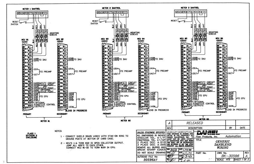
138
Operating instructions Electrical switching facility pco
 Operating instructions Electrical switching facility pco from software version V1.33 on TABLE OF CONTENTS 1. Before you start... 4 1.1 Brief description... 4 1.2 Using this manual... 4 2. pco integrated
RAM 4021 Operation Manual
 RAM 4021 Operation Manual Worldwide Manufacturer of Gas Detection Solutions TABLE OF CONTENTS RAM 4021 For your safety...3 Description...3 Set-up mode...4 Annunciator lights/alarms...4 Operation...5 Calibration...6
BUBBLER CONTROL SYSTEM
 BUBBLER CONTROL SYSTEM Description: The HDBCS is a fully automatic bubbler system, which does liquid level measurements in water and wastewater applications. It is a dual air compressor system with, air
User's Manual. Heavy Duty Dissolved Oxygen Meter. Model
 User's Manual Heavy Duty Dissolved Oxygen Meter Model 407510 Introduction Congratulations on your purchase of Extech's Heavy Duty Dissolved Oxygen / Temperature Meter which simultaneously displays Dissolved
Pegas 4000 MF Gas Mixer InstructionManual Columbus Instruments
 Pegas 4000 MF Gas Mixer InstructionManual Contents I Table of Contents Foreword Part I Introduction 1 2 1 System overview... 2 2 Specifications... 3 Part II Installation 4 1 Rear panel connections...
Scoreboard Operator s Instructions MPC Control
 Scoreboard Operator s Instructions MPC Control Some features on the keyboard overlay may not be included on the particular model being operated. Since 1934 Retain this manual in your permanent files 1/21/2011
ACV-10 Automatic Control Valve
 ACV-10 Automatic Control Valve Installation, Operation & Maintenance General: The Archer Instruments ACV-10 is a precision automatic feed rate control valve for use in vacuum systems feeding Chlorine,
Vehicle-mounted meters, pump supplied
 Purpose This inspection procedure outline (IPO) defines the minimum tests which must be performed to ensure that basic volumetric measuring devices comply with the legislation. Application Vehicle-mounted
A4s Operation Manual
 A4s Operation Manual Safety Instruction Please read this manual carefully, also with related manual for the machinery before use the controller. For installing and operating the controller properly and
Hydro-Control V User Guide
 Hydro-Control V User Guide Hydronix Part no: HD0193 Version 2.3.0 Revision date: July 2006 1 COPYRIGHT Neither the whole or any part of the information contained in nor the product described in this documentation
Specifications and information are subject to change without notice. Up-to-date address information is available on our website.
 www.smar.com Specifications and information are subject to change without notice. Up-to-date address information is available on our website. web: www.smar.com/contactus.asp LD302 - AssetView HMI LD302
! Warning, refer to accompanying documents.
 About this Manual To the best of our knowledge and at the time written, the information contained in this document is technically correct and the procedures accurate and adequate to operate this instrument
A4 Operation Manual. Fig.1-1 Controller Socket Diagram
 A4 Operation Manual Safety Instruction Please read this manual carefully, also with related manual for the machinery before use the controller. For installing and operating the controller properly and
Safety Manual. Process pressure transmitter IPT-1* 4 20 ma/hart. Process pressure transmitter IPT-1*
 Safety Manual Process pressure transmitter IPT-1* 4 20 ma/hart Process pressure transmitter IPT-1* Contents Contents 1 Functional safety 1.1 General information... 3 1.2 Planning... 4 1.3 Instrument parameter
TorMinal. Operating instructions V OCE-Rev.L_EN
 TorMinal Operating instructions 1-138 3800-20310V001-112016-0-OCE-Rev.L_EN Table of contents General Information... 4 Symbols... 4 General safety instructions... 4 Safety information for batteries... 4
GasSense NDIR User Manual
 INDEX INDEX... 1 1. OVERVIEW... 2 2. TECHNICAL DATA... 3 3. SPECIFICATIONS... 4 4. PRODUCT DESCRIPTION... 5 4.1 Mechanical details... 5 4.2 Piping... 7 4.3 Connections... 7 5. INSTALLATION... 10 6. CALIBRATION
RAM 4021-DPX Operation Manual
 RAM 4021-DPX Operation Manual Worldwide Manufacturer of Gas Detection Solutions TABLE OF CONTENTS ABL 4021-DPX / RAM 4021-DPX For Your Safety... 3 Description... 3 Setup Mode... 4 Lights/Alarms... 4 Operation...
92831 TEL: (714) FAX:
 FAX:") Document N0. 1800-03 Copyright 2010 Terra Universal Inc. All rights reserved. Revised Sept. 2010 Terra Universal, Inc. TerraUniversal.com 800 S. Raymond Ave. Fullerton, CA 92831 TEL: (714) 578-6000 FAX:
Document N0. 1800-03 Copyright 2010 Terra Universal Inc. All rights reserved. Revised Sept. 2010 Terra Universal, Inc. TerraUniversal.com 800 S. Raymond Ave. Fullerton, CA 92831 TEL: (714) 578-6000 FAX:
RAM Operation Manual. Worldwide Manufacturer of Gas Detection Solutions
 RAM 4021 Operation Manual Worldwide Manufacturer of Gas Detection Solutions TABLE OF CONTENTS RAM 4021 For Your Safety... 2 Description.... 2 Setup Mode.... 2 Lights/Alarms.... 3 Operation.... 4 Calibration....
Location of CC Number if not located with the identification:
 This checklist is used for Technical Policy U. Evaluating electronic digital indicators submitted separate from a measuring element. This section is intended for lab testing only. Is permanence necessary?
ELIMINATOR INSTRUCTIONS Table of Contents
 ELIMINATOR INSTRUCTIONS Table of Contents 1. PRACTICE MODE A. Toggling from Full to Pro Tree B. Toggling from 1 to 2 Users C. Toggling from Auto to Manual Reset D. Setting the Delay Boxes E. Setting a
INSTRUCTION MANUAL MP4AR Remote Convection Gauge Range: 1 x 10⁻³ Torr to 1 x 10+3 Torr
 INSTRUCTION MANUAL MP4AR Remote Convection Gauge Range: 1 x 10⁻³ Torr to 1 x 10+3 Torr A DIVISION OF THE FREDERICKS COMPANY 2400 PHILMONT AVE. HUNTINGDONVALLEY, PA 19006 PARTS LIST 1 3 4 2 # QTY ITEM DESCRIPTION
BGA244 Binary Gas Analyzer
 Quick Start Guide Revision 1.0 Certification Warranty Service certifies that this product met its published specification at the time of shipment. This product is warranted against defects in materials
RAM Operation Manual
 RAM 4021-1 Operation Manual Worldwide Manufacturer of Gas Detection Solutions TABLE OF CONTENTS RAM 4021-1 For Your Safety... 2 Description... 2 Setup Mode... 3 Lights/Alarms... 3 Operation... 4 Calibration...
Model GFC 7000T CO 2 Analyzer (Addendum to GFC 7000TA Manual, PN 07272)
") Manual Addendum Model GFC 7000T CO 2 Analyzer (Addendum to GFC 7000TA Manual, PN 07272) P/N M07273 DATE 06/11/13 TELEDYNE ELECTRONIC TECHNOLOGIES Analytical Instruments 16830 Chestnut Street City of Industry,
Manual Addendum Model GFC 7000T CO 2 Analyzer (Addendum to GFC 7000TA Manual, PN 07272) P/N M07273 DATE 06/11/13 TELEDYNE ELECTRONIC TECHNOLOGIES Analytical Instruments 16830 Chestnut Street City of Industry,
BUBBLER CONTROL SYSTEM
 BUBBLER CONTROL SYSTEM Description: The LDBCS is a fully automatic bubbler system, which does liquid level measurements in water and wastewater applications. It is a dual air compressor system with, air
Vehicle- or rack-mounted liquefied gas meters, pump supplied
 Purpose This inspection procedure outline (IPO) defines the minimum tests which must be performed to ensure that basic volumetric measuring devices comply with the legislation. Application Rack/fixed metering
Agilent Flowmeter ADM1000
 Agilent Flowmeter ADM1000 Operating Instructions Notices Agilent Technologies, Inc. 2003 No part of this manual may be reproduced in any form or by any means (including electronic storage and retrieval
RAM Operation Manual. Worldwide Manufacturer of Gas Detection Solutions
 RAM 4021 Operation Manual Worldwide Manufacturer of Gas Detection Solutions TABLE OF CONTENTS RAM 4021 For Your Safety... 2 Description.... 2 Setup Mode.... 2 Lights/Alarms.... 3 Operation.... 4 Calibration....
The Univentor 1250 Anaesthesia Unit
 THE UNIVENTOR 1200/1250 ANAESTHESIA UNIT The Univentor 1250 Anaesthesia Unit TABLE OF CONTENTS EDITION 1 Section 1 - WARRANTY & SERVICE 1.1. WARRANTY 2 1.2. DAMAGED SHIPMENTS 2 1.3. SERVICE 2 Section 2
INSTRUCTION MANUAL. FLOW CONTROL DRAWERS MANUAL / PLC CONTROL SERIES Model Version Perma Pure LLC Tel:
 PERMA PURE INSTRUCTION MANUAL FLOW CONTROL DRAWERS MANUAL / PLC CONTROL SERIES Model 3300 Version 4.06 Perma Pure LLC Tel: 732-244-0010 P.O. Box 2105, 8 Executive Drive Tel: 800-337-3762 (toll free US)
T i m i n g S y s t e m s. RACEAMERICA, Inc. P.O. Box 3469 Santa Clara, CA (408)
") RACEAMERICA T i m i n g S y s t e m s Demo Tree Controller Owner s Manual Models 3204D, 3204DW & 3204DX Rev D RACEAMERICA, Inc. P.O. Box 3469 Santa Clara, CA 95055-3469 (408) 988-6188 http://www.raceamerica.com
RACEAMERICA T i m i n g S y s t e m s Demo Tree Controller Owner s Manual Models 3204D, 3204DW & 3204DX Rev D RACEAMERICA, Inc. P.O. Box 3469 Santa Clara, CA 95055-3469 (408) 988-6188 http://www.raceamerica.com
DPC-30 DPC-100. Reference Manual
 DPC-30 DPC-100 Reference Manual 1. Introduction 1.1 Description The Martel DPC Digital Pneumatic Calibrator improves upon traditional dial gauge pneumatic calibrators. The Martel DPC improves accuracy,
SPECIFICATIONS APCEPH1
 APCEPH1 ph CONTROLLER SPECIFICATIONS APCEPH1 Input voltage 120 Volts AC Maximum amperage 14.5 amps @ 120 VAC ph Accuracy +/- 0.2 ph ph Control range Adjustable 4.5 8.5 ph Weight < 1 lbs Dimensions 3" x
RAM 4021-PR. Operation Manual. Worldwide Manufacturer of Gas Detection Solutions
 RAM 4021-PR Operation Manual Worldwide Manufacturer of Gas Detection Solutions TABLE OF CONTENTS RAM 4021-PR For Your Safety... 2 Description.... 2 Setup Mode.... 2 Lights/Alarms.... 3 Operation.... 4
URC Voltage Sensor SEN-VOLT for use with MRX units containing sensor ports
 URC Voltage Sensor SEN-VOLT for use with MRX units containing sensor ports URC Voltage Sensor SEN-VOLT 2013 Universal Remote Control, Inc. The information in this Owner s Manual is copyright protected.
MIL-STD-883G METHOD
 STEADY-STATE LIFE 1. PURPOSE. The steady-state life test is performed for the purpose of demonstrating the quality or reliability of devices subjected to the specified conditions over an extended time
These Terms and conditions apply to audit trails incorporated in weighing and measuring devices and systems 1.
 Title: Terms and Conditions for the Approval of Metrological Audit Trails Effective Date: 2006-03-16 Page: 1 of 9 Revision: 1.0 Application These Terms and conditions apply to audit trails incorporated
In Vivo Scientific, LLC INSTRUCTION MANUAL
 CO 2 Controller In Vivo Scientific, LLC INSTRUCTION MANUAL CONTENTS CONTENTS...1 ABOUT THIS MANUAL...2 INTRODUCTION...2 Cautions and Warnings...2 Parts List...2 Unpacking...2 INSTRUMENT DESCRIPTION...3
PROPORTIONING VALVE. Model 150 INSTRUCTION MANUAL. March 2017 IMS Company Stafford Road
 PROPORTIONING VALVE Model 150 INSTRUCTION MANUAL March 2017 IMS Company 10373 Stafford Road Telephone: (440) 543-1615 Fax: (440) 543-1069 Email: sales@imscompany.com 1 Introduction IMS Company reserves
MODEL 6600 Rev. B4 USER'S MANUAL LAVERSAB INC., 505 GILLINGHAM LANE. SUGAR LAND TX (281) FAX: (281)
 FAX: (281)") MODEL 6600 Rev. B4 USER'S MANUAL LAVERSAB INC., 505 GILLINGHAM LANE. SUGAR LAND TX 77478 (281) 325-8300 FAX: (281) 325-8399 Email: aservice@laversab.com Document Number : 9051 REV B4 Date: June 07, 2011.
MODEL 6600 Rev. B4 USER'S MANUAL LAVERSAB INC., 505 GILLINGHAM LANE. SUGAR LAND TX 77478 (281) 325-8300 FAX: (281) 325-8399 Email: aservice@laversab.com Document Number : 9051 REV B4 Date: June 07, 2011.
Technical Data Sheet MF010-O-LC
 Technical Data Sheet MF010-O-LC - 1 - 1. Properties The oxygen measuring system MF010-O-LC determines the oxygen content in gas mixtures up to a temperature of 250 C. It is particularly suitable for the
Roller AC Servo System
 Safely Instruction Roller AC Servo System HMI-15 User Manual Please read this manual carefully, also with related manual for the machinery before use the controller. For installing and operating the controller
Built-in Purge Control Functions
 Built-in Purge Control Functions Why clean a sensor? As the velocity sensor was calibrated clean, operating it clean also preserves the best calibration. Any build up of material on a thermal sensor tends
PTG100 Precision Test Gauge
 PTG100 Precision Test Gauge User Manual PD1007 Rev B 03/28/2014 Palmer Instruments Inc. 234 Old Weaverville Road Asheville, NC 28804 Toll Free: 800-421-2853 Phone: 828-658-3131 Fax: 828-658-0728 Email:
AHE58/59 AC Servo System
 AHE58/59 AC Servo System HMI-12 User Manual Safely INstruction Please read this manual carefully, also with related manual for the machine head before use. For perfect operation and safety, installing
210 Series Transmitter with External Electrochemical Sensor
 210 Series Transmitter with External Electrochemical Sensor INSTRUCTIONS Installation and Operation of the AMC-210 Series Transmitter with External Electrochemical Sensor IMPORTANT: Please read these installation
MODEL 100 NITROGEN INFLATION CART
 MODEL 100 NITROGEN INFLATION CART Installation & Operation Information Branick Industries, Inc. 4245 Main Avenue P.O. Box 1937 Fargo, North Dakota 58103 REV120106 P/N: 81-0113 TABLE OF CONTENTS SAFETY
Golf Performance Monitors. PureContact Operating Guide. Version of 9
 PureContact Operating Guide Version 5.1 www.zelocity.com 1 of 9 PureContact Metrics: Measured Ball Velocity Carry Distance Other PureContact Features: Instantly, Accurately Displays & Records Critical
Calibration Gas Instrument INSTRUCTION MANUAL. Release I. Advanced Calibration Designs, Inc.
 Advanced Calibration Designs, Inc. Calibration Gas Instrument INSTRUCTION MANUAL Release I www.goacd.com Instruction Manual Gas Generator Release I TABLE OF CONTENTS I. General Description Page 2 II. Start-Up
L 100. Bubble-Tube Level System. Installation, Operation and Maintenance Instructions
 L 100 Bubble-Tube Level System Installation, Operation and Maintenance Instructions Figure 1 Contents Section Description Page 1.0 Introduction 2 2.0 Specifications 3 3.0 Installation 3 4.0 Warranty 6
MP-70/50 Series Scoreboard Controller User Guide
 MP-70/50 Series Scoreboard Controller User Guide Document No. 98-0002-29 Revision Date: 08-01-12 Effective with firmware ver. 3.05 CONVENTIONS USED IN THIS GUIDE Introduction The following conventions
Basic Nitriding Sampling System Hydrogen Analyzer with Calculated % DA, % NH 3, and K N Values. Operations Manual
 Basic Nitriding Sampling System Hydrogen Analyzer with Calculated % DA, % NH 3, and K N Values Operations Manual Please read, understand, and follow these instructions before operating this equipment.
Safety Manual VEGAVIB series 60
 Safety Manual VEGAVIB series 60 NAMUR Document ID: 32005 Contents Contents 1 Functional safety... 3 1.1 General information... 3 1.2 Planning... 4 1.3 Adjustment instructions... 6 1.4 Setup... 6 1.5 Reaction
Compiled by: B Beard. Approved by: SH Carstens. Description of requirements and procedures for compact provers to be used as verification standards.
 1. Scope Description of requirements and procedures for compact provers to be used as verification standards. 2. Reference documents Trade Metrology Act SANS1698 3. Policy A. BASIC REQUIREMENTS Compact
FireHawk M7 Interface Module Software Instructions OPERATION AND INSTRUCTIONS
 FireHawk M7 Interface Module Software Instructions OPERATION AND INSTRUCTIONS WARNING THE WARRANTIES MADE BY MSA WITH RESPECT TO THE PRODUCT ARE VOIDED IF THE PRODUCT IS NOT USED AND MAINTAINED IN ACCORDANCE
BI-680 Online Dissolved Oxygen Controller Instruction Manual
 BI-680 Online Dissolved Oxygen Controller Instruction Manual BANTE INSTRUMENTS CO., LTD BI-680 Online Dissolved Oxygen Controller 1 Introduction Thank you for selecting the BI-680 online dissolved oxygen
SAPCON. User Manual. Capacitance Continuous Level Indicator. . Introduction. . General Description. . Principle of Operation. .
 User Manual Capacitance Continuous Level Indicator Comprehensive User s Manual. Introduction. General Description. Principle of Operation. Specifications. Connection Diagrams. Quick Calibration Chart.
Ultima. X Series Gas Monitor
 Ultima X Series Gas Monitor Safety Manual SIL 2 Certified " The Ultima X Series Gas Monitor is qualified as an SIL 2 device under IEC 61508 and must be installed, used, and maintained in accordance with
Application Notes. SLP85xD Load Cells
 Application Notes Load Cells Table of Contents 1 Introduction 3 2 Description of the Filling Cycle 4 3 Filling Optimization 7 4 Filling Monitor 8 4.1 Weight-Based Filling Monitor... 8 4.2 Time-Based Filling
SCIENTIFIC DATA SYSTEMS, INC. Depth Tension Line Speed Panel. DTLS Manual
 SCIENTIFIC DATA SYSTEMS, INC. Depth Tension Line Speed Panel DTLS Manual This document contains proprietary information. Copyright 2015 Scientific Data Systems, Inc. All rights reserved. 1 Depth Tension
LENNOX SLP98UHV DIAGNOSTIC CODES
 Code Status of Equipment Action required to clear and recover - Idle mode (Decimal blinks at 1 Hertz -- 0.5 second ON, 0.5 second OFF) A Cubic feet per minute (cfm) setting for indoor blower (1 second
E2K-L. Liquid Level Sensor That Is Unaffected by the Color of the Pipe or Liquid. Liquid Level Sensor. Ordering Information
 Liquid Level EK-L CSM_EK-L_DS_E 3 Liquid Level That Is Unaffected by the Color of the or Liquid Mount to bypass pipes. Fit a wide range of pipe diameters: 8 to mm or to mm Built-in Amplifiers to save space.
Description of Device Parameters Proline Prowirl 200 HART. Vortex flowmeter. Products Solutions Services. Main menu Language.
 GP01019D/06/EN/02.15 71308256 Valid as of version 01.02.zz (Device firmware) Products Solutions Services of Device Parameters Proline Prowirl 200 HART Vortex flowmeter XXXXXXXXX 20.50 Main menu 0104-1
CONSOLE-320 ENGLISH. 230A: CONSOLE-320 with cable data output Item 230B: CONSOLE-320 with cable + wireless radio data output
 CONSOLE-320 Item 230A: CONSOLE-320 with cable data output Item 230B: CONSOLE-320 with cable + wireless radio data output Table of contents 1. INTRODUCTION...2 1.1 Power supply...2 1.2 Connections...2 1.3
LM6 LEATHER MOISTURE METER
 CHECK LINE BY ELECTROMATIC LM6 LEATHER MOISTURE METER Operating Manual TABLE OF CONTENTS 1.0 Introduction..... 2 1.1 Operation and handling 1.2 Measuring procedure 2.0 Calibration curves....... 3 2.1 Selection
Overview. Front Panel: Keypad and Display
 Overview The GA-200B is an analyzer that integrates a gas sampling system with sensors to measure and display the concentrations of oxygen and carbon dioxide in a sample as the percentage of a gas in the
NB/NBR NITROGEN BOOSTER FOR AVIATION SERVICE
 NB/NBR NITROGEN BOOSTER FOR AVIATION SERVICE INSTALLATION, OPERATION & MAINTENANCE MANUAL INTERFACE DEVICES, INC. 230 Depot Road, Milford, CT 06460 Ph: (203) 878-4648, Fx: (203) 882-0885, E-mail: info@interfacedevices.com
OPERATING INSTRUCTIONS V 5.3
 1 OPERATING INSTRUCTIONS V 5.3 DM 06/ 07 EGO 06/ 07 ION /SP8 MINI Proto Matrix 07 Proto Rail Shocker Seventh Element, Inc WARNING Failure to follow directions may result in damage to board. Do not pull
Marschalk Model # 94000
 Marschalk Model # 94000 12-volt DC Portable oil-less Air Compressor Operation Manual 27250006 REV 1 9/13/05 Table of Contents CHAPTER 1: SYSTEM DESCRIPTION... 5 FUNCTION AND THEORY... 5 SYSTEM COMPONENTS...
ASE SOLVENT CONTROLLER INSTALLATION INSTRUCTIONS Dionex Corporation
 ASE SOLVENT CONTROLLER INSTALLATION INSTRUCTIONS 2000 Dionex Corporation Document No. 031277 Revision 03 April 2000 2000 Dionex Corporation All rights reserved worldwide. Printed in the United States of
Agilent Auxiliary Gas Module AGM 2. User s Guide
 Agilent Auxiliary Gas Module AGM 2 User s Guide Notices Agilent Technologies, Inc. 1992, 1996, 1999, 2010 No part of this manual may be reproduced in any form or by any means (including electronic storage
AA100 Acoustic Actuator
 AA100 Acoustic Actuator Operating Manual REV. A, September 2001 COPYRIGHT 2001. ALL RIGHTS RESERVED Return Procedure It is necessary to obtain from ORE Offshore a Returned Material Evaluation (RMA) number
OEM Manual. MODEL ½ Digit DRUM SCALE
 OEM Manual MODEL 4020-3 ½ Digit DRUM SCALE Scaletron Industries, Ltd. Bedminster Industrial Park 53 Apple Tree Lane P.O. Box 365 Plumsteadville, PA 18949 USA Toll Free: 1-800-257-5911 (USA & Canada) Phone:
6 digital caliper with case
 6 digital caliper with case Model 98563 Set up And Operating Instructions Diagrams within this manual may not be drawn proportionally. Due to continuing improvements, actual product may differ slightly
Safety Manual VEGAVIB series 60
 Safety Manual VEGAVIB series 60 Contactless electronic switch Document ID: 32002 Contents Contents 1 Functional safety... 3 1.1 General information... 3 1.2 Planning... 4 1.3 Adjustment instructions...
User s Guide Temperature Sensor Converter TSC-599
 User s Guide Temperature Sensor Converter TSC-599 ILX Lightwave Corporation 31950 Frontage Road Bozeman, MT, U.S.A. 59715 U.S. & Canada: 1-800-459-9459 International Inquiries: 406-556-2481 Fax 406-586-9405
700 SERIES BMS II BUBBLER MONITORING SYSTEM
 1 700 SERIES BMS II BUBBLER MONITORING SYSTEM VISIT OUR WEBSITE AT SIGMACONTROLS.COM 700 SERIES BMS II MANUAL 062114 2 TABLE OF CONTENTS INTRODUCTION 3 Physical Specifications WIRING 5 PROGRAMMING & SETUP..
SG36KTL-M Quick Installation Guide. 1 Unpacking and Inspection
 SG36KTL-M Quick Installation Guide This guide provides a general instruction of the installation procedures of SG36KTL-M. In no case shall this guide substitute for the user manual or related notes on
Alimak Lift Control, ALC II User s Manual
 Alimak Lift Control, ALC II User s Manual This manual is only applicable if the manufacturing number indicated below corresponds to the manufacturing number stamped on the identification sign of the equipment.
MODEL 6500 Rev. E USER'S MANUAL
 MODEL 6500 Rev. E USER'S MANUAL LAVERSAB INC., 505 GILLINGHAM LANE SUGAR LAND TX, 77478 (281) 325-8300 FAX: (281) 325 8399 Email: service@laversab.com Document Number : 9014 REV.E Date: June 6, 2005. WARRANTY
RGC-IR Remote Gas Calibrator for IR400
 Remote Gas Calibrator for IR400 The information and technical data disclosed in this document may be used and disseminated only for the purposes and to the extent specifically authorized in writing by
SPS-5. Rate Computing Scale. Operation Manual
 SPS-5 Rate Computing Scale Operation Manual Revision 1.0 October 17, 1996 1996 Transcell Technology, Inc. Contents subject to change without notice. Transcell Technology, Inc. 975 Deerfield Parkway Buffalo
Race Screen: Figure 2: Race Screen. Figure 3: Race Screen with Top Bulb Lock
 Eliminator Competition Stand Alone Mode - Instruction Manual Main Menu: After startup, the Eliminator Competition will enter the Main Menu. Press the right/left arrow buttons to move through the menu.
Series 3730 and Series 3731 EXPERTplus Valve Diagnostics with Partial Stroke Test (PST)
") Series 3730 and Series 3731 EXPERTplus Valve Diagnostics with Partial Stroke Test (PST) Application Positioner firmware for early detection of control valve faults giving maintenance recommendations. Valid
Series 3730 and Series 3731 EXPERTplus Valve Diagnostics with Partial Stroke Test (PST) Application Positioner firmware for early detection of control valve faults giving maintenance recommendations. Valid
MONSOON 6V Pump Control System
 MONSOON 6V Pump Control System Installation and Operating Instructions Please pass these instructions on to the operator of this equipment. INTRODUCTION MONSOON 6V Pump Controller The MONSOON 6V pump control
Digital Vacuum Regulator
 Temperature Control for Research and Industry Digital Vacuum Regulator User s Manual Model 300 INDEX SECTION PAGE 1. QUICK OPERATING INSTRUCTIONS........................... 3 Safety Notices.................................................
SPECIFICATIONS ATTENTION
 VPS 504 S06 Installation Manual - P/N 80122 - Ed. 01/09 VPS 504 S06 and S05 Valve Proving System Installation Instructions VPS 1 6 Gases Natural gas, air and other inert gases. NOT suitable for butane
MP15 Jockey Pump Controller
 Setup and Operating Instructions MP15 Jockey Pump Controller This manual provides general information, installation, operation, maintenance, and system setup information for Metron Model MP15 Jockey Pump
Model 106 DPI "Micro-switch" Installation and Operating Instructions
 Mid-West Instrument Model 106 DPI "Micro-switch" Installation and Operating Instructions BULLETIN NO. IM116DPImicro/09A Replaces --- INSPECTION Before installation carefully check the Model Number on each
92831 TEL: (714) FAX:
 FAX:") Document No. 1800-75 Respiration Test Chamber Copyright 2010 Terra Universal Inc. All rights reserved. Revised September 2010 Terra Universal, Inc. TerraUniversal.com 800 S. Raymond Ave. Fullerton, CA
Document No. 1800-75 Respiration Test Chamber Copyright 2010 Terra Universal Inc. All rights reserved. Revised September 2010 Terra Universal, Inc. TerraUniversal.com 800 S. Raymond Ave. Fullerton, CA
REASONS FOR THE DEVELOPMENT
 7 Series 7 Series +24VDC VDC OUTPUT MICROPROCESS. E P IN EXH OUT 7 Series 7 ø,8 8 7 Series 9 5 8 9 7 Series Display features The proportional regulator has a 3 /2 digit display and a three-pushbutton
HAI UPB 15A Relay Switch and Auxiliary Switch Installation and Operating Instructions
 HAI UPB 15A Relay Switch and Auxiliary Switch Installation and Operating Instructions For the following Models: 40A00-1 HAI 15A Relay Switch (referred to as HAI UPB Wall Switch, in this document), and
The benefits of the extended diagnostics feature. Compact, well-proven, and flexible
 ABB MEASUREMENT & ANALYTICS TECHNICAL INFORMATION PositionMaster EDP300 Extended Diagnostics Compact, well-proven, and flexible The benefits of the extended diagnostics feature The PositionMaster EDP300
The HumiSys. RH Generator. Operation. Applications. Designed, built, and supported by InstruQuest Inc.
 The HumiSys RH Generator Designed, built, and supported by InstruQuest Inc. Versatile Relative Humidity Generation and Multi-Sensor System The new HumiSys with single or dual RH probes capabilities is
PART 5 - OPTIONS CONTENTS 5.1 SYSTEM EXPANSION 5-3
 PART 5 - OPTIONS CONTENTS Para Page 5.1 SYSTEM EXPANSION 5-3 5.2 SENSORS 5-3 5.2.1 Trim Angle Sensor 5-3 5.2.2 Mast Rotation Sensor 5-3 5.2.3 Heel Angle Sensor 5-3 5.2.4 Barometric Pressure Sensor 5-3
UNITY 2 TM. Air Server Series 2 Operators Manual. Version 1.0. February 2008
 UNITY 2 TM Air Server Series 2 Operators Manual Version 1.0 February 2008 1. Introduction to the Air Server Accessory for UNITY 2...2 1.1. Summary of Operation...2 2. Developing a UNITY 2-Air Server method
Operating Instructions
 ELECTRIC AND GAS FRYER AUTOMATIC BASKET LIFT SYSTEM Operating Instructions 302 Spencer Lane P.O. Box 5369 San Antonio, Texas 78201 (800) 525-8130 (210) 731-5000 Fax: (210) 731-5099 www.ultrafryer.com PREFACE
Pressure switch Type BCP
 Data sheet Pressure switch Type BCP The BCP type is a series of dedicated switches for safety and monitoring of steam and hot water boilers. The BCP incorporates a single-pole changeover microswitch where
DeeterFlow Automatic Liquid Dispenser
 DeeterFlow Automatic Liquid Dispenser Table of Contents 1. Introduction... 3 2. Installation... 4 3. Volume Accuracy... 5 4. Operator Controls... 5 5. Operating States... 6 5.1 Power-up... 6 5.2 Ready