Measure to solve technical subjects in UCS replacement. Experimental Fast Reactor Joyo Oarai R&D Center, JAEA
|
|
|
- Melvin Preston
- 5 years ago
- Views:
Transcription


1 1 Measure to solve technical subjects in UCS replacement Experimental Fast Reactor Joyo Oarai R&D Center, JAEA
2 2 Configuration of equipment in UCS replacement

 UCS GL-6100 (Sodium level during operation)")
 UCS (during construction) GL-9460 : Bottom of UCS")
3 6330mm 2710mm 2266mm Structure of UCS GL-3110 : Top of R/P Large rotating plug Small rotating plug S-R/P GL-3130 : Top of UCS φ1160mm φ1130mm 444mm φ1070mm φ1010mm UCS guide Sleeve (GS) UCS GL-6100 (Sodium level during operation) φ1100mm φ1060mm UCS (Weight : ~16.5ton) UCS (during construction) GL-9460 : Bottom of UCS GL-9490 : Top of subassemblies 3
4 Outline of UCS replacement Wire jack-up equipment UCS Screw jack-up equipment Cask Door valve Cask S-R/P L-R/P UCS Temporary pit cover Guide tube Ed-UCS is extracted through small-diameter part. (1) Jack-up of ed-ucs (2) Retrieval of ed-ucs (3) Installation of n-ucs ed-ucs : existing damaged UCS Plant condition : n-ucs : new UCS - Fuel S/As are remained in reactor vessel. >>> Sodium level is maintained at 50 mm below top of fuel S/A. - Temperature of sodium is approximately 200deg-C, and temperature of cover gas is approximately 140~160deg-C. 4
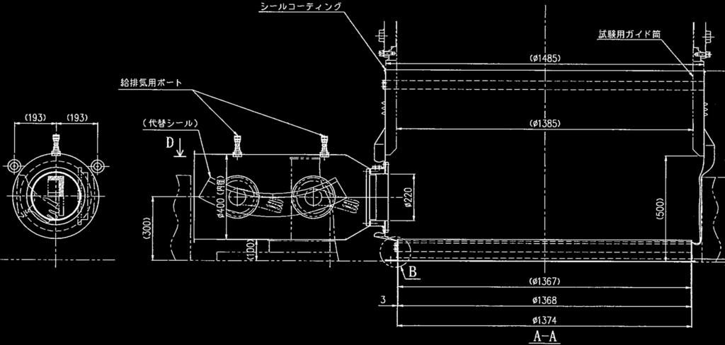
5 Equipment Configuration in ed-ucs jack-up ed-ucs jack-up equipment Adjustment bolt in horizontal Guide pin Temporary pit cover Jack-up ed-ucs to 1000 mm Load measuring device Guide tube Vinyl bag Guide bolt R/P ed-ucs Level measuring device Inflate seal Support Hanging plate Hanging bolt Liner fastening bolt Gap monitoring equipment Fitting area monitoring equipment 5
6 6 Equipment Configuration in ed-ucs retrieval Cask Wire jack equipment Base frame for wire jack equipment Door-valve ed-ucs Retrieve ed-ucs into cask Ed-UCS bottom observation equipment Simplified boundary R/P
7 7 Equipment Configuration in n-ucs installation n-ucs Install n-ucs R/P
8 8 Measure to solve technical subjects in UCS replacement
9 9 Major subjects in UCS replacement (1) Prevention of deformation of ed-ucs and GS (2) Detection of interference and contact between ed-ucs and GS (3) Insurance of cover gas boundary (4) Measure for unexpected incident (Ex. failure of ed-ucs jack-up/pulling-up)
10 Measure to prevent of deformation > To prevent deformation of ed-ucs and GS, allowable load is investigated using Abaqus/Standard Version with 3-D modeling. > To prevent interference and contact between ed-ucs and GS, allowable inclination is investigated. And, to achieve a strict control, following two measures are implemented in the design of jack-up equipment. - Applying three-point suspension - Inclination monitoring with level- and load-measuring devices 10
11 Investigation of allowable load in ed-ucs jack-up and pulling-up Pulling height (mm) Allowable load (t) Resistance 0 ~ Sodium bridge shearing force notes Jack-up speed : <2mm/h *1 2 ~ Sodium bridge shearing force 484 ~ Interference resistance 862 ~ 1.73 Contact resistance *1: Deformation at the point of force application of wringing force (3.37t) is unlikely owing to its thick structure. However, in the case that sodium bridge shearing is incomplete, there may be a risk of guide sleeve deformation due to rapid release of the wringing force. jack-up speed is limited to below 2 mm/h to prevent permanently deforming guide sleeve. To prevent deformation of ed-ucs and guide sleeve with applying above allowable load 11
12 Investigation of allowable load in n-ucs installation Pulling height (mm) Allowable load (t) Resistance ~ ~ ~ Interference resistance (between UCS bottom and GS) Interference resistance (between UCS and GS) Contact resistance (between UCS and GS) UCS bottom reaches top of φ1160mm part of GS UCS bottom reaches top of φ1070mm part of GS Bottom of UCS φ1050mm part reaches top of φ1070mm part of GS Height : 6145mm Height : 4482mm Height : 4104mm 12
13 13 Requirement to jack-up equipment 1. Load regulation system to prevent deformation of ed- UCS and GS Allowable load (Ex. during ed-ucs jack-up) : 0.72t (0~484mm) 1.09t (484~862mm) 1.73t (862mm~) 2. Inclination control and monitoring system to prevent interference and contact between ed-ucs and GS Allowable inclination (Ex. during ed-ucs jack-up) : 0.039deg (0.69mm/m)* * Assuming a conservative 2.5 mm gap
14 Structure of Jack-up equipment (1/2) Screw jack Three screw jacks are located uniformly in a concentric configuration. Vertical Screw jack displacement measuring device Handle Temporary pit cover 1100mm Guide tube Temporary boundary Jack-up equipment Base mechanism of screw jack Servomotor R/P UCS Jack holder base Jack-up equipment is installed on guide tube. Prevent interference and contact between ed-ucs and GS by means of adjusting guide tube location together with jack-up equipment. Load measuring device Hanging plate 吊り蓋 Manual : 0.025mm/rotation Auto : 0.017~1mm/s Level measuring device Required Max. load : ~40t ( total load of three screw jack ) 14


 Guide bolt Reduction gear UCS (Dummy)")
15 15 Structure of Jack-up equipment (2/2) Top of jack-up equipment Connection part of screw jack Screw jack (connection) Hanging plate Load measuring device Level measuring device Hanging bolt Vertical displacement measuring device (in tube) Handle (attachment) Guide tube (Dummy) Guide bolt Reduction gear UCS (Dummy) Servomotor
 ~5m ~7m ~9m GS (Dummy) UCS 模擬体 UCS (Dummy) > Dummy UCS can be jacked-up")


16 Mock-up test for jack-up equipment To confirm performance of jack-up equipment using mock-up Configuration of mock-up Testing frame Guide tube (Dummy) ~5m ~7m ~9m GS (Dummy) UCS 模擬体 UCS (Dummy) > Dummy UCS can be jacked-up until 1000mm. > Emergency stop system with over-load detection is performed successfully. > Inclination of dummy UCS is ensured below deg. (0.69mm/m) due to strict synchronization of three screw jacks. * Inclination of dummy UCS is almost constant : <0.015deg. (Fluctuation : <0.01deg.) Above achievement are confirmed using dummy UCS with assuming maximum tolerance * Gap between dummy UCS and dummy guide sleeve : 0.65mm in minimum (5mm in nominal design) 16
17 17 Measure to Detection of interference and contact between ed-ucs and GS > Direction method of interference and contact is investigated by means of calculation of off-set direction of center of gravity based on loads of three screw jack. > Adjustment bolts are prepared to adjust guide tube location together with jack-up equipment. > It is confirmed that dummy UCS can be pulled up with adjustment of guide tube location to escape interference and contact in mock-up test.
18 Load (kg) Load (kg) 18 Load behavior in interference and contact (example) 1100 Interference 第 5 回 1200 Contact Load is changed gradually 第 5 回 Load is changed rapidly Pulling height (mm) Pulling height (mm)
19 Load ratio (local load / total load) Development of detection method of interference and contact Z2 Z3 Z1 Location of Interference (Ex.(1)) Z2 Center of gravity(2) Center of gravity(1) Z Ex.(1) : at 0 deg. Ex.(2) : at 210 deg. Z1 Location of Interference (Ex.(2)) Estimated behavior of eccentric load 1. Z1, Z2, Z3 have eccentric load caused by interference and contact 2. Center of gravity based on loads of Z1, Z2, Z3 is moved from (1) to (2). >>> Location of interference and contact is investigated by off-set direction of center of gravity (balance of load ratio) Location of interference (deg.) 19
20 Off-set direction of center of gravity (deg : Test result) Investigation of detection method of interference and contact Configuration of equipment Test result 360 Z :Set point :Test result 180 Dummy plate Z3 120 Z1 Center of gravity(1) Center of gravity(2) 60 0 Off-set direction of center of gravity agrees with direction of interference Direction of interference (deg : set point) - Direction of interference can be investigated by means of calculation of offset direction of center of gravity based on loads of three screw jack. - Ed-UCS can be pulled up by means of adjustment of guide tube location in horizontal using dummy of lower part of UCS with maximum tolerance (gap : 0.65mm in minimum (nominal gap is 5mm)). 20
21 21 Measure to insure cover gas boundary > Because radioactivity in cover gas is quite low due to long time reactor shutdown, prevention of impurities contamination is just required in this work. > Vinyl bag with slight positive pressure is installed as main temporary boundary. > Assuming breakage of vinyl bag, simplified boundary is prepared during period that it is impossible to access to near vinyl bag due to high dose rate. And, in order to prevent impurities contamination, pressure of simplified boundary is kept slight negative. > Reduction of vinyl bag temperature is conducted by means of Ar gas blow in order to secure integrity of vinyl bag
22 Operation procedure of temporary boundary Simplified boundary Ar gas blow down Ar gas 150~200Pa Ar gas supply Protection plate R/P Ar gas <150Pa Vinyl bag Air -50~0Pa > With positive pressure of vinyl bag (simplified boundary : negative), impurities contamination is prevented, assuming breakage of vinyl bag. > In order to secure integrity of vinyl bag, high temperature Ar gas rising is inhibited by means of Ar gas blow of ~100L/min (initial value). Argon blow rate is adjusted as required (thermometer is installed in vinyl bag). > Protection plate is installed in vinyl bag with assuming unexpected negative pressure of vinyl bag in order prevent contact between UCS and vinyl bag. 22


23 23 Ref. Structure of vinyl bag Tap (M8) Vinyl bag Vinyl bag Guide tube Attachment
24 Argon gas blow to secure integrity of vinyl bag Empirical equations concerning with argon gas blow down (1) Re>Gr/3 * Empirical equation applied to argon gas flow rate evaluation for Joyo fuel handling machine (2) Gr/(Re 1.43 Fr 0.35 )<32.5 * Empirical equation to prevent that high temperature argon gas flow into argon gas blow down channel (3) Gr/(Re 1.43 (1/De))<3.74 * Empirical equation to prevent that high temperature argon gas reach at top of argon gas blow down channel Re : Reynolds number Gr : Grashof number Fr : Froude number De : Equivalent diameter Results (1) ~1020 L/min (2) ~106 L/min (3) ~21 L/min Initial flow rate of argon gas blow down : 100L/min * With monitoring using thermometer installed in vinyl bag 24
25 Measure for unexpected incident (Ex. failure of ed-ucs jack-up/pulling-up) - Recovering ed-ucs to initial position (or holding ed-ucs on position at the time) - Discussing measure based on obtained data (stroke, load, inclination, etc.) - Re-jack-up and pulling-up of ed-ucs with discussed measure 1. Beforehand discussion for recovering ed-ucs to initial position (1) Investigation of allowable load In order to prevent deformation of ed-ucs and GS during recovering work, load is regulated below allowable load which is same as ed-ucs jack-up. (2) Training using mock-up Specific boundary equipment for recovering is prepared, then equipment performance and working procedure are confirmed through mock-up test. 2. Preparation of data accumulation system for unexpected failure of ed-ucs jack-up and pulling-up (1) Observation equipment in R/V UCS fitting area visual monitoring equipment etc. are prepared (2) Obtaining detailed data of load and inclination Although jack-up speed is 60mm/min in maximum, in order to obtain data of load and inclination behavior in detail, jack-up speed is regulated 0.33mm/min (2mm/h) in initial state (pulling height : 0 ~ 2mm). (3) Preparation of mock-up for investigation of cause Data of above (2) is analyzed and evaluated using prepared mock-up for investigation of cause. 25
Mitsubishi Heavy Industries Technical Review Vol. 53 No. 4 (December 2016)
") Completion of Joyo Experimental Fast Reactor Upper Core Structure Replacement - Development of Fast Reactor Core Internal Equipment Replacement method - 65 MASAHIDE HARA *1 JUNYA TANAKA *2 HIROYOSHI OKAZAKI
Completion of Joyo Experimental Fast Reactor Upper Core Structure Replacement - Development of Fast Reactor Core Internal Equipment Replacement method - 65 MASAHIDE HARA *1 JUNYA TANAKA *2 HIROYOSHI OKAZAKI
Measure to solve technical subjects in MARICO-2 subassembly retrieval. Experimental Fast Reactor Joyo Oarai R&D Center, JAEA
 Measure to solve technical subjects in MARICO-2 subassembly retrieval Experimental Fast Reactor Joyo Oarai R&D Center, JAEA 1 Status of MARICO-2 test subassembly (S/A) Rotating Plug Hold-down shaft Hold-down
The water supply for a hydroelectric plant is a reservoir with a large surface area. An outlet pipe takes the water to a turbine.
 Fluids 1a. [1 mark] The water supply for a hydroelectric plant is a reservoir with a large surface area. An outlet pipe takes the water to a turbine. State the difference in terms of the velocity of the
On-Off Connector Skirt
 On-Off Connector Skirt Retrievable Packers & Accessories The On-Off Connector Skirt is compact, reliable, fully sealing, J-type tubing disconnect device that automatically engages and releases with a small
TEST PROTOCOL VERIFICATION OF THE BEHAVIOUR OF A MECHANICAL COMPRESSION COUPLING DURING SETTLEMENT
 TEST PROTOCOL VERIFICATION OF THE BEHAVIOUR OF A MECHANICAL COMPRESSION COUPLING DURING SETTLEMENT Nova Siria factory, Roletto, April 6, 2011 Introduction Mechanical steel compression couplings (CC) are
Corrugated Hose Loop Calculations
 Corrugated Hose Loop Calculations The loop installation is one of the most common application for metal hoses. It allows the flexible hose assembly to work properly. Care must always be exercised to ensure
Typical factors of safety for bearing capacity calculation in different situations
 Typical factors of safety for bearing capacity calculation in different situations Density of soil: In geotechnical engineering, one deals with several densities such as dry density, bulk density, saturated
Item 404 Driving Piling
 Item Driving Piling 1. DESCRIPTION Drive piling. 2. EQUIPMENT 2.1. Driving Equipment. Use power hammers for driving piling with specified bearing resistance. Use power hammers that comply with Table 1.
VPPL VARIABLE DISPLACEMENT AXIAL-PISTON PUMPS FOR INTERMEDIATE PRESSURE SERIES 10
 / ED VPPL VARIABLE DISPLACEMENT AXIAL-PISTON PUMPS FOR INTERMEDIATE PRESSURE SERIES OPERATING PRINCIPLE The VPPL are variable displacement axial-piston pumps with variable swash plate, suitable for applications
DNVGL-CP-0187 Edition March 2016
 CLASS PROGRAMME Type approval DNVGL-CP-0187 Edition March 2016 The electronic pdf version of this document, available free of charge from http://www.dnvgl.com, is the officially binding version. FOREWORD
Air Saving Valve. Series ASQ. Series ASR. Pressure Valve. Flow valve TMH ASD AS AS-FG AS-FP AS-FM ASP ASN AQ ASV AK VCHC ASS. r r AS-FE KE 10 0.
 Air Saving Valve Series R Pressure Valve Series Q Flow Valve P r.9.7 2..3.1 D -FE KE -FG -FP -FM.1.2.2.3 pressure (MPa) -D -T P ow valve Fl N AQ V e n by o i t p nsum n stroke o c r i r a Cuts g the retu
Application and Sizing
 Application and Sizing Energy accumulator: It is improbable that an hydraulic system use all of its capacity without interruptions. An hydropneumatic accumulator can store a certain amount of fluid that
The Discussion of this exercise covers the following points:
 Exercise 3-2 Orifice Plates EXERCISE OBJECTIVE In this exercise, you will study how differential pressure flowmeters operate. You will describe the relationship between the flow rate and the pressure drop
Supplementary Operation, Assembly, Maintenance Manual for F3-42 model and optional attachments
 FERMENATOR TM Supplementary Operation, Assembly, Maintenance Manual for F3-42 model and optional attachments Congratulations on your purchase, and thank you for selecting the Fermenator TM stainless conical
Air distribution systems Circular displacement outlet with adjustable damper VA-ZD...
 Air distribution systems Circular displacement outlet with adjustable damper VA-ZD... DS 059 E 05.010/1 Construction design and function Preliminary remarks Displacement air outlets enable to extract pollutants
Application of Simulation Technology to Mitsubishi Air Lubrication System
 50 Application of Simulation Technology to Mitsubishi Air Lubrication System CHIHARU KAWAKITA *1 SHINSUKE SATO *2 TAKAHIRO OKIMOTO *2 For the development and design of the Mitsubishi Air Lubrication System
Experimental Analysis of Inclined Narrow Plate-Fins Heat Sink under Natural Convection
 Experimental Analysis of Inclined Narrow Plate-Fins Heat Sink under Natural Convection A.A.WALUNJ 1, D.D.PALANDE 2 1,2 PG student, Mechanical Department, MCOERC, Nashik Abstract Steady state natural convection
Experimental Verification of Integrated Pressure Suppression Systems in Fusion Reactors at In-Vessel Loss-of -Coolant Events
 Experimental Verification of Integrated Pressure Suppression Systems in Fusion Reactors at In-Vessel Loss-of -Coolant Events K. Takase 1), H. Akimoto 1) 1) Japan Atomic Energy Research Institute (JAERI),
Integral type Differential pressure flowmeter VNT Series
 Integral type Differential pressure flowmeter VNT Series OUTLINE VH series Wafer-Cone differential pressure flowmeter and high precision differential pressure transmitter are integrated into one flowmeter.
Experiment Instructions. Circulating Pumps Training Panel
 Experiment Instructions Circulating Pumps Training Panel Experiment Instructions This manual must be kept by the unit. Before operating the unit: - Read this manual. - All participants must be instructed
for Building facilities Industrial facilities etc.,multipurpose Pilot operated type(high capacity)
") for Building facilities Industrial facilities etc.,multipurpose Pilot operated type(high capacity This is a Pilot operated pressure reducing valve. It is suitable to install in the steam lines with the
for Building facilities Industrial facilities etc.,multipurpose Pilot operated type(high capacity This is a Pilot operated pressure reducing valve. It is suitable to install in the steam lines with the
Leaks from Unit-3 PCV and steam release in a large amount
 Attachment 3-8 Leaks from Unit-3 PCV and steam release in a large amount 1. Background At Unit-3 the suppression chamber (S/C) vent line configuration was completed at 08:41 on March 13 th and the dry
CONTENTS 1. INTRODUCTION DESCRIPTION OF TEST SAMPLE TEST RIG GENERAL ARRANGEMENT TEST SEQUENCE...7
 Page 2 of 22 CONTENTS 1. INTRODUCTION...3 2. DESCRIPTION OF TEST SAMPLE...4 3. TEST RIG GENERAL ARRANGEMENT...6 4. TEST SEQUENCE...7 5. SUMMARY AND CLASSIFICATION OF TEST RESULTS...8 6. WATERTIGHTNESS
USE OF TIRE PRESSURE TO IMPROVE THE CALIBRATION OF THE BICYCLE W...
 Page 1 of 8 PROPOSED USE OF TIRE PRESSURE TO IMPROVE THE CALIBRATION OF THE BICYCLE WHEEL IN THE MEASUREMENT OF ROAD-RACING COURSES ABSTRACT NEVILLE F WOOD nfwood@hotmail.com Revised 6/3/05 I have shown
HTR Systems and Components
 IAEA Course on HTR Technology Beijing, 22-26.October 2012 HTR Systems and Components Dr. Gerd Brinkmann Dieter Vanvor AREVA NP GMBH Henry-Dunant-Strasse 50 91058 Erlangen phone +49 9131 900 96840/95821
AIRMOUNT VIBRATION ISOLATION
 MOUNT VIBRATION ISOLATION SELECTION AND ISOLATION FORMULA Refer to the selection guide on page 33 for Airmount load and isolation capabilities. Follow this procedure: 1. LOAD CAPACITY Select one or two
MUELLER. A Wall Type. Indicator Post. Reliable Connections. General Information 2. Technical Data/ Dimensions 3. Installation 4-5.
 Installation Instructions manual MUELLER table of contents PAGE A-20814 Wall Type General Information 2 Technical Data/ Dimensions Installation 4-5 Maintenance 6 Parts 7 Indicator Post! WARNING: 1. Read
Hermetic Compressor Manifold Analysis With the Use of the Finite Element Method
 Purdue University Purdue e-pubs International Compressor Engineering Conference School of Mechanical Engineering 2008 Hermetic Compressor Manifold Analysis With the Use of the Finite Element Method Rinaldo
SENSITIVITY ANALYSIS OF THE FIRST CIRCUIT OF COLD CHANNEL PIPELINE RUPTURE SIZE FOR WWER 440/270 REACTOR
 PROCEEDINGS OF THE YEREVAN STATE UNIVERSITY Physical and Mathematical Sciences 216, 2, p. 57 62 P h y s i c s SENSITIVITY ANALYSIS OF THE FIRST CIRCUIT OF COLD CHANNEL PIPELINE RUPTURE SIZE FOR WWER 44/27
NO SMOKING WHEN OXYGEN IS IN USE.
 GENERAL NO SMOKING WHEN OXYGEN IS IN USE. The oxygen system provides oxygen as required for up to 19 passengers and 2 cockpit crew members. Therapeutic oxygen outlets are also available in the cabin. OXYGEN
Experiment 13: Make-Up Lab for 1408/1420
 Experiment 13: Make-Up Lab for 1408/1420 This is only for those that have approval. Students without approval will not be allowed to perform the lab. The pre-lab must be turned in at the beginning of lab.
1.0 - OPENING AND CLOSING THE DOOR
 The purpose of this manual is to provide the user with instructions on how to safely open and close, how to conduct routine maintenance, and how to install the PEI TWINLOCK Closure on a pressure vessel.
TAM Single SeT inflatable
 TAM Single SeT inflatable ReTRievAble PAckeRS Sets with pressure only Releases with straight pull or rotate Ideal for horizontal applications Sets in casing or open hole Runs on tubing, coiled tubing,
IGUMA - IGU Design Limitations
 1/5 IGUMA - IGU Design Limitations Introduction Insulating Glass Units (IGU s) are being used more frequently in domestic and commercial buildings to provide improved insulation, comfort, condensation
KTM OM-2 SPLIT BODY FLOATING BALL VALVES INSTALLATION AND MAINTENANCE INSTRUCTIONS
 Before installation these instructions must be fully read and understood SECTION 1 - STORAGE 1.1 Preparation and preservation for storage All valves should be properly packed in order to protect the parts
TRAVSMART permanent single-cable horizontal lifeline system
 The Travsmart single-line system provides a smooth travel. It allows the traveler to move freely over the intermediate anchors, minimizing wear and eliminating user assistance. The user s hands remain
TURBINE SEAL: AXIAL TYPE DESIGN
 TURBINE SEAL: AXIAL TYPE DESIGN Our axial type seals are specifically designed for application to hydroelectric turbines and large water pumps for sewage handling, filtration, irrigation, and more. Our
HANDBOOK SAFETY DEVICES. Ed SAFETY DEVICES DS-ED 01/ ENG 1
 HANDBOOK Ed. 2017 DS-ED 01/2017 - ENG 1 CHAPTER 9 BURSTING DISC DEVICES IN SERIES 3070 SCOPE Use: protection against possible overpressure of the apparatuses listed below, with regard to the operating
V10K GAS FEED SYSTEM WALLACE & TIERNAN PRODUCTS
 V10K GAS FEED SYSTEM WALLACE & TIERNAN PRODUCTS V10K SYSTEM: PROVEN TECHNOLOGY WORLDWIDE IN USE Since Charles F. Wallace and Martin F. Tiernan discovered the first chlorine gas feed system in 1913 the
THE BRIDGE COLLAPSED IN NOVEMBER 1940 AFTER 4 MONTHS OF ITS OPENING TO TRAFFIC!
 OUTLINE TACOMA NARROWS BRIDGE FLOW REGIME PAST A CYLINDER VORTEX SHEDDING MODES OF VORTEX SHEDDING PARALLEL & OBLIQUE FLOW PAST A SPHERE AND A CUBE SUMMARY TACOMA NARROWS BRIDGE, USA THE BRIDGE COLLAPSED
STATISTICAL INVESTIGATION IMPACT OPENING OF MINE SHAFT DETACHING HOOKS
 Anglo Technical Division A Division of Anglo Operations Limited STATISTICAL INVESTIGATION OF THE RISK OF ACCIDENTAL IMPACT OPENING OF MINE SHAFT DETACHING HOOKS De Wet Strydom Johann Wannenburg Presentation
In this course you will learn the following
 Module 11 : Example study of robots Lecture 40 : NATARAJ a case study of a 6-legged robot Objectives In this course you will learn the following Mobile Robots Legged Robots Nataraj Robot Nataraj Development
Series V47 Temperature Actuated Modulating Valves
 PSC0302 European Refrigeration Controls Catalogue Catalog Section 7 Product Bulletin V47 Series V47 Temperature Actuated Modulating Valves Introduction The V47 modulating water valves regulate the flow
Third measurement MEASUREMENT OF PRESSURE
 1. Pressure gauges using liquids Third measurement MEASUREMENT OF PRESSURE U tube manometers are the simplest instruments to measure pressure with. In Fig.22 there can be seen three kinds of U tube manometers
Booster Regulator/Air Tank
 Booster Regulator/Air Tank Increase factory air pressure by up to 4 times! Air-only operation requires no power supply, reduces heat generation, and Boost pressure allows easy installation. NEW Renewed
Air Saving Valve reduction in 40% air consumption 40% air consumption Air consumption reduction ratio (%) Flow valve Flow valv
 Flow valve Flow valv") CAT.ES-173 A Air Saving Valve % reduction in air consumption Cuts air consumption by operating the return stroke at a reduced pressure. valve Pressure Air consumption reduction ratio (%) 3 1.1.1...3 pressure
CAT.ES-173 A Air Saving Valve % reduction in air consumption Cuts air consumption by operating the return stroke at a reduced pressure. valve Pressure Air consumption reduction ratio (%) 3 1.1.1...3 pressure
COMPFIRE CCFT-FP_550_55_ September 2010 Fin Plate Connection to Circular Concrete-Filled Tube Test Result
 Reaction Frame Macalloy Bars Camera 3 Support Beam α Oven Bar Camera 2 Link Bar Camera 1 Tested Connection Jack Bar Electrical Furnace Reaction Frame Load Jack v2_5 April 2011 1 Oven Bar Link Bar View
NE 405/505 Exam 2 Spring 2015
 NE 405/505 Exam 2 Spring 2015 (80%) 1) A PWR with UTSGs is operating at 100% power, BOC, with control rods all out in automatic control when a failure in the speed pump controller results in all feed pumps
SV5 Safety Valve Installation and Maintenance Instructions
 3120036/3 IM-S13-12 CH Issue 3 SV5 Safety Valve Installation and Maintenance Instructions 1. General specification 2. Supply 3. Before fitting the valve 4. Installation 5. Damage prevention 6. Commissioning
Load Ring bolted > VWBG < in pink
 RUD-Art.-Nr.: 8503693-EN / 03.014 Load Ring bolted > VWBG < in pink EN Safety instructions This safety instruction/declaration has to be kept on file for the whole lifetime of the product. Translation
Vibration isolation system 1VIS10W. User manual
 Vibration isolation system 1VIS10W User manual Standa 2014 Table of contents 1. General information 3 1.1. Introduction 3 1.1.1. Safety 5 1.2. Location of the table 5 1.3. Air supply requirements 5 2.
Pneumatic Function Fittings Metric & Inch
 Metric & nch Sensor Fitting Very compact units asy tube insertion for rapid assembly of pneumatic circuits Positive tube anchorage Simpler pneumatic systems liminates need for electrical reed switches
Installation, commissioning and servicing instructions
 488.03 www.reece.com.au Pressure reducing s Installation, commissioning and servicing instructions Function Pressure reducing s are installed in residential water systems to reduce and stabilise inlet
Pressure Reducing Valve DMV 755
 Pressure Reducing Valve DMV 755 Nominal size DN 10 50 Nominal size 3/8 2 Nominal pressure PN 10 bar Features pressure setting range 1 to 9 bar control valve for reliable reduction of system pressures to
Job Sheet 1 Blade Aerodynamics
 Job Sheet 1 Blade Aerodynamics The rotor is the most important part of a wind turbine. It is through the rotor that the energy of the wind is converted into mechanical energy, which turns the main shaft
Football Equipment. 5 9/16" Gooseneck Goalposts
 5 9/16" Gooseneck Goalposts Football Equipment FB55CG 5 9/16" Gooseneck College Goalposts Applies also to FB55CG-SY and FB55CG-WT Goalposts shall meet all NCAA rules. Goalposts shall be of the single bent
T004.BioTector TOC Analyzer Pressure and Flow Test failure analysis
 March 2013 PAGE 1 of 5 T004.BioTector TOC Analyzer Pressure and Flow Test failure analysis Section 1: Pressure Test. Theory of operation. The Mass Flow Controller (MFC) in the BioTector is used to confirm
Pressure Reducing Valve for Air A-COS-10
 172-65254MA-03 (-10) 26 June 2015 ISO 9001/ ISO 14001 Manufacturer Kakogawa, Japan is approved by LRQA LTD. to ISO 9001/14001 Pressure Reducing for Air -10 Copyright 2015 by TLV CO., LTD. All rights reserved
MSC Guidelines for Vents, Fills and Sounds
 S. J. Kelly, CDR, Chief of Engineering Division References: a. 46 CFR 56.50-85 & 56.50-90 (Subchapter F) b. 46 CFR 32.55, 36.20-1 & 38.20 (Subchapter D) c. 46 CFR 119.445 & 119.450 (Subchapter K) d. 46
INSTRUCTION MANUAL FOR UNDERWATER OPERATION
 INSTRUCTION MANUAL FOR UNDERWATER OPERATION FOR HYDRAULIC HAMMER MODELS: GH7, GH9, GH10, GH12, GH15, GH18, GH23, GH30, GH40, GH50, E208, E210A, E213, E216, E220, E225, E240A, E260A Use Genuine NPK Parts
Size Selection & Installation of QSZH-125
 Product Installation Procedure (PIP) No: PIP-101 Revision: 2 Dated: January 2012 Title:- Size Selection & Installation of QSZH-125 Prepared By: Name: Clive Benning Date: January 2012 Reviewed & Approved
VERTICAL BLADDER TANK
 Balanced Pressure Proportioning System Reliable Foam System Requiring Only Water Power Perfect For Tight Spaces UL Listed, ASME, National Board Registered Bladder-UL162 Approved, High Tensile Pressure
DC5A. Cyclone Separator Trap for Air. Copyright 2015 by TLV Co., Ltd. All rights reserved ISO 9001/ ISO MA-03 (DC5A) 19 June 2015
 19 June 2015") 172-65205MA-03 (DC5A) 19 June 2015 ISO 9001/ ISO 14001 Manufacturer Kakogawa, Japan is approved by LRQA LTD. to ISO 9001/14001 Cyclone Separator Trap for Air DC5A Copyright 2015 by TLV Co., Ltd. All rights
172-65205MA-03 (DC5A) 19 June 2015 ISO 9001/ ISO 14001 Manufacturer Kakogawa, Japan is approved by LRQA LTD. to ISO 9001/14001 Cyclone Separator Trap for Air DC5A Copyright 2015 by TLV Co., Ltd. All rights
SIKA Ba_ODWT15_en 05/2018. Operating manual for oil deadweight tester 0.015% accuracy ODWT15
 SIKA Ba_ODWT15_en 05/2018 Operating manual for oil deadweight tester 0.015% accuracy ODWT15 Table of Contents 1 introduction...1 1.1 general product description... 1 1.2 operating principle... 1 2 general
LIFTING MAGNETS ERIEZ MAGNETICS
 MJ-2300E Installation, Operation and Maintenance Instructions LIFTING MAGNETS ERIEZ MAGNETICS HEADQUARTERS: 2200 ASBURY ROAD, P.O. BOX 10608, ERIE, PA 16514 0608 U.S.A. WORLD AUTHORITY IN ADVANCED TECHNOLOGY
The Industrial Accident Resulted from the Failure of Bolt
 The Industrial Accident Resulted from the Failure of Bolt Hyun Wook YEO 1, Jae Min LEE 2 and Sang Won CHOI 1, * 1 Occupational Safety and Health Research Institute, Korea Occupational Safety and Health
9 Mixing. I Fundamental relations and definitions. Milan Jahoda revision Radim Petříček, Lukáš Valenz
 9 ixing ilan Jahoda revision 14-7-017 Radim Petříček, Lukáš Valenz I Fundamental relations and definitions ixing is a hydrodynamic process, in which different methods are used to bring about motion of
Self-operated Pressure Regulators for special applications
 Self-operated Pressure Regulators for special applications Type 2357-31 Pressure Build-up Regulator with safety function and integrated excess pressure valve Application Pressure regulators for cryogenic
CHAPTER 5: VACUUM TEST WITH VERTICAL DRAINS
 CHAPTER 5: VACUUM TEST WITH VERTICAL DRAINS 5.1 Introduction Using surcharging as the sole soil consolidation mean can take a long time to reach the desired soil settlement. Soil consolidation using prefabricated
MUD 1. Vent check valves. Instruction and maintenance manual.
 MUD 1 Vent check valves Instruction and maintenance manual. Version: 04-02-2011. 2 List of Contents 1. INTRODUCTION 3 1.1 The Problem... 3 1.2 The Solution... 3 2. RULES AND REGULATIONS 3 2.1 General requirements....
Learn more at
 Full scale model tests of a steel catenary riser C. Bridge 1, H. Howells 1, N. Toy 2, G. Parke 2, R. Woods 2 1 2H Offshore Engineering Ltd, Woking, Surrey, UK 2 School of Engineering, University of Surrey,
TECHNICAL MANUAL HEAVY DUTY HORIZONTAL MICRO-COMPRESSOR Reference: RCMPH
 TECHNICAL MANUAL HEAVY DUTY HORIZONTAL MICRO-COMPRESSOR Reference: RCMPH THIS MANUAL IS INTENDED FOR TECHNICAL STAFF IN CHARGE OF THE INSTALLATION, THE OPERATION AND THE MAINTENANCE OF THIS PRODUCT CAUTION!
Bridge Plugs, Ball Drop & Caged Ball Plugs For Zone Isolation
 Bridge Plugs, Ball Drop & Caged Ball Plugs For Zone Isolation ADVANTAGE composite bridge plug, caged ball and ball drop (flow thru) frac plug provide a means to isolate multiple zones during high pressure
HORIZONTAL BLADDER TANK
 Balanced Pressure Proportioning System Reliable Foam System Requiring Only Water Power Perfect For Low Ceilings UL Listed, ASME, National Board Registered Bladder-UL162 Approved, High Tensile Pressure
Magnetic level switch type MR783 Instruction Manual
 Magnetic level switch Magnetic level switch type MR783 1. DESCRIPTION page 3 1.1 Operation page 3 1.2 Application page 3 1.3 Description page 3 2. SPECIFICATIONS page 3 2.1 Service Conditions page 4 2.2
Tidland Series 'C' Knifeholder INSTALLATION MANUAL Rigid Cartridge Class I, II, III Shear Slitting
 Tidland Series 'C' Knifeholder INSTALLATION MANUAL Rigid Cartridge Class I, II, III Shear Slitting Please read and understand all the instructions before you install the Tidland Series 'C' Knifeholder.
USER MANUAL. 1. Principle of operation. 2. Delivery condition. SPRING-LOADED SAFETY VALVES zarmak. Edition: 07/2016 Date: V (ex.
 ZETKAMA Sp. z o.o. ul. 3 Maja 12 PL 57-410 Ścinawka Średnia SPRING-LOADED SAFETY VALVES zarmak USER MANUAL 782V (ex. 782) Edition: 07/2016 Date: 01.07.2016 TABLE OF CONTENTS 1. Principle of operation 2.
Protecting your punching tool investment. Application-related problems and solutions
 Protecting your punching tool investment Application-related problems and solutions Article reprinted with permission from the May 2000 issue of The FABRICATOR. By Nick Tarkany Economic shortcuts in the
Allspeeds Ltd. Royal Works, Atlas St Clayton le Moors Accrington Lancashire England BB5 5LW. Tel +44 (0)
") Allspeeds Ltd. Royal Works, Atlas St Clayton le Moors Accrington Lancashire England BB5 5LW Tel +44 (0)1254 615100 www.allspeeds.co.uk WIRE ROPE CUTTER WCS75HDZ PRODUCT CODE No. 980482 INSTRUCTIONS FOR
Allspeeds Ltd. Royal Works, Atlas St Clayton le Moors Accrington Lancashire England BB5 5LW Tel +44 (0)1254 615100 www.allspeeds.co.uk WIRE ROPE CUTTER WCS75HDZ PRODUCT CODE No. 980482 INSTRUCTIONS FOR
Hand & mechanical directional valves
 www.atos.com Table E5-3/E Hand & mechanical directional valves ISO 44 sizes 6,, 6 and 25 H- Hand & mechanical operated directional valves are spool type, three or four way, two or three position valves,
The Discussion of this exercise covers the following points: Pumps Basic operation of a liquid pump Types of liquid pumps The centrifugal pump.
 Exercise 2-3 Centrifugal Pumps EXERCISE OBJECTIVE In this exercise, you will become familiar with the operation of a centrifugal pump and read its performance chart. You will also observe the effect that
BULK SOLIDS HANDLING Valve Solutions Unlock the Potential
 BULK SOLIDS HANDLING Valve Solutions Unlock the Potential The valve people EBRO BULK A WIDE RANGE OF VALVE SOLUTIONS FOR CEMENT, CHEMICALS, PLASTICS, FOOD, NUTRACEUTICALS, PHARMACEUTICALS Gravity Discharge
SHUR-LOK CORPORATION TECHNICAL SALES BULLETIN
 Page 1 of 11 1. SCOPE: 1.1. This provides the minimum design, port preparation, and installation and removal requirements for SLAS5103 plugs and is applicable when specified on engineering drawings. These
Displacement 12, , Maximum flow rate (at 1450 rpm) bar.
 bar.") 00/07 ED PVD VARIABLE DISPLACEMENT VANE PUMPS SERIES 0 OPERATING PRINCIPLE The PVD pumps are variable displacement vane pumps with a mechanical type of pressure compensator. They allow instantaneous adjustment
00/07 ED PVD VARIABLE DISPLACEMENT VANE PUMPS SERIES 0 OPERATING PRINCIPLE The PVD pumps are variable displacement vane pumps with a mechanical type of pressure compensator. They allow instantaneous adjustment
TRP 63 / TRP 72 / TRP 93 / TRP 110 CENTRE LATHES
 TRP 63 / TRP 72 / TRP 93 / TRP 110 CENTRE LATHES BASIC PARAMETERS Max. torque on spindle: Max. weight of workpiece between centres: 5,600 Nm 6 tonnes Turning length: 1,000 to 16,000 mm In their basic version
Contribution to the snow protection solutions for pitched roofs
 Contribution to the snow protection solutions for pitched roofs Jozef Oláh1 and Michal Šida1,* 1 Slovak University of Technology in Bratislava, Faculty of Civil Engineering, Radlinského 11, 810 05 Bratislava,
SEALANT BEHAVIOR OF GASKETED-SEGMENTAL CONCRETE TUNNEL LINING
 4 th International Conference on Earthquake Geotechnical Engineering June 25-28, 2007 Paper No.1636 SEALANT BEHAVIOR OF GASKETED-SEGMENTAL CONCRETE TUNNEL LINING Faisal SHALABI 1, Edward CORDING 2, and
Tidland Series 'C' Knifeholder INSTALLATION MANUAL Swing Cartridge Class II, III Shear Slitting
 Tidland Series 'C' Knifeholder INSTALLATION MANUAL Swing Cartridge Class II, III Shear Slitting Please read and understand all the instructions before you start to install the Tidland Series 'C' Knifeholder.
North American sealing solutions Bridge Plug Ball Drop Frac Plug Caged Ball Frac Plug
 North American sealing solutions Bridge Plug Ball Drop Frac Plug Caged Ball Frac Plug The North American Sealing Solutions composite bridge plug, caged ball and ball drop (flow thru) frac plug provide
Air Saving Valve. Pressure Valve Flow Valve
 Air Saving Valve Series Series Pressure Valve Flow Valve % reduction in air consumption Cuts air consumption by operating the return stroke at a reduced pressure. valve Pressure Air consumption reduction
SPCH/ Blowing block
 > > for linear stretch blow moulding machines > > Compact and safe design > > Best suited for PET bottles up to litres, depending on cycle time Technical features Medium: Compressed air (purity class 3..3
Operating Instructions VETTER Pipe and Test Sealing Bags
 Emergency Pneumatics. Operating Instructions VETTER Pipe and Test Sealing Bags Article No. 87044600 Vetter GmbH I 06/11 I Changes and errors excepted. Vetter Pipe and Test Sealing Bags Contents 1. Introduction...2
Measuring range Δp (span = 100%) Pa
 Pa") 4.4/ RLE 5: Volume-flow controller, continuous How energy efficiency is improved Enables demand-led volume flow control for the optimisation of energy consumption in ventilation systems. Areas of application
4.4/ RLE 5: Volume-flow controller, continuous How energy efficiency is improved Enables demand-led volume flow control for the optimisation of energy consumption in ventilation systems. Areas of application
SPWE Series. Setup Instructions. Version 2.0
 SPWE Series Integrated Tank Weighing Assembly Setup Instructions Version 2.0 Load Cell Central follows a policy of continuous improvement and reserves the right to change specifications without notice.
Engineering Data Sheet
 Page 1 of 6 CE MARKING AND THE PRESSURE EQUIPMENT DIRECTIVE 97/23/EC Valves must be installed into a well designed system and it is recommended that the system be inspected in accordance with the appropriate
WATER METERS.
 WATER METERS Can be installed Pulse output with both plug & play system horizontal and vertical No straight Higher sections accuracy required U0 D0 Water engineering High resistance Its operation is based
DB Bridge Plug. Features. Benefits. Applications
 DB Bridge Plug The WELLFIRST Premium Cast Iron Bridge Plug designed to run on electric line. Rated between 2000-10000-psi differential, and 300 F from above and below. Features Field Proven Design Constructed
WARNING: READ THE GENERAL INFORMATION MANUAL INCLUDED FOR OPERATING AND SAFETY PRECAUTIONS AND OTHER IMPORTANT INFORMATION.
 GSR500 Ram Assembly General Description The GSR500 single post lift / ram uses a 3-1/4 air powered cylinder, which is welded to a heavy gauge base. It is normally used to raise and lower a fluid handling
A REVIEW OF THE 2000 REVISIONS TO ANSI 2530/API MPMS 14.3/AGA REPORT NO. 3 - PART2 Paul J. LaNasa CPL & Associates
 A REVIEW OF THE 2000 REVISIONS TO ANSI 2530/API MPMS 143/AGA REPORT NO 3 - PART2 Paul J LaNasa CPL & Associates PO Box 801304, Houston, TX 77280-1304 ABSTRACT Periodically, natural gas measurement standards
Geotech 1.66 Auto-Reclaimer
 Geotech 1.66 Auto-Reclaimer Installation and Operation Rev 9 8/31/06 Part # 16600165 TABLE OF CONTENTS CHAPTER 1: SYSTEM DESCRIPTION... 3 FUNCTION AND THEORY... 3 SYSTEM COMPONENTS... 4 CHAPTER 2: SYSTEM