MECHANISM AND COUNTERMEASURES OF WAVE OVERTOPPING FOR LONG-PERIOD SWELL IN COMPLEX BATHYMETRY. Hiroaki Kashima 1 and Katsuya Hirayama 1
|
|
|
- Randell Parks
- 5 years ago
- Views:
Transcription
1 MECHANISM AND COUNTERMEASURES OF WAVE OVERTOPPING FOR LONG-PERIOD SWELL IN COMPLEX BATHYMETRY Hiroaki Kashima 1 and Katsuya Hirayama 1 Recently, coastal disasters due to long-period swells induced by heavy storms and catastrophic typhoons have increased at Japanese coasts and harbors. Long-period swells are more susceptible to the bottom bathymetry of the offshore deep water region and their wave heights locally increase due to the concentration of wave energy caused by the complex bottom bathymetry in the relatively shallow water region. In addition, the wave overtopping rate may increase due to the long waves in front of the seawall induced by the long-period swells. However, the spatial relationship between wave characteristics and wave overtopping discharges in the complex bathymetry are not well known owing to a lack of detailed measurements. In this study, model experiments were conducted by using a large basin to investigate the spatial characteristics of wave transformation and wave overtopping focusing on the heavy wave overtopping damages caused by the arrivals of long-period swells at the Shimoniikawa Coast in Effective countermeasures against wave overtopping are also discussed based on their characteristics. Keywords: long-period swell; long wave; wave overtopping; seawall; jetty; submerged breakwater INTRODUCTION Many Japanese harbors directly face the Pacific Ocean and the Japan Sea where both high wind waves and swells often occur due to heavy storms. Although breakwaters and seawalls have been designed to protect against these severe waves, coastal disasters due to long-period swells induced by heavy storms and catastrophic typhoons have increased at Japanese coasts and harbors recently. For example, the collapses of seawalls and inundation behind the defending reclaimed area in Kuji Harbor were caused by heavy wave overtopping due to 14.5 s swells in 2006 (Hirayama et al., 2008). The seawall along the Shonan Coast in the Odawara region facing the Pacific Ocean was damaged by 14.2 s swells in Moreover, severe damage to property and inhabitants in the Ashizaki district of Nyuzen town on the Shimoniikawa Coast was caused by long-period swells with high wave heights in 2008 (Kawasaki et al., 2008). Thus, it is necessary to take countermeasures urgently to reduce the severe damage caused by long-period swells. Fortunately, long-period swells have been observed at several wave observation stations along the Japanese coastline (Kashima et al. 2009). These long-period swells have narrower-band spectra than those of wind waves, and wave groupings with high waves can appear in the time series of their wave profiles. They steepen due to wave shoaling and refraction under the effects of bottom bathymetry in the deep water region because their relative water depth is shallower than that of wind waves. Moreover, long-period swells with wave groupings have effects on wave overtopping discharges on a seawall. Kashima and Hirayama (2010) have suggested that the long waves associated with the development of wave groupings are generated by second nonlinear interactions between their component waves. Furthermore, wave overtopping discharges on a seawall increase due to the effect of instantaneous water surface elevation as a result of the specific long waves in front of the seawall for unidirectional long-period swells. Therefore, it is important to consider not only the characteristics of long-period swells with wave groupings but also long waves when discussing wave overtopping discharges for longperiod swells. There have been several studies on the characteristics of long-period swells. Kashima and Hirayama (2009) discussed the difference between the transformation of long-period swells and wind waves on the complex bathymetry including the deep water region. Long-period swells are more susceptible to the bottom bathymetry of the deep water region than wind waves and their wave heights locally increase due to the concentration of wave energy in relatively shallow water. Tajima et al. (2009) and Fukase et al. (2010), analyzing observed data and focusing on the damage features, stated that the concentration of wave energy on the damaged area is caused by the interactions among waves, bathymetry and near shore currents. In particular, the slowly varying wave-induced nearshore currents have a significant impact on the local concentration of waves around sharply-changing coastal bathymetries. On the other hand, Fukase et al. (2009) investigated the generation of long waves induced by nonlinear interactions between the component waves of long-period swells at the Shimoniikawa 1 Coastal and Ocean Engineering Field, Port and Airport Research Institute, Nagase, Yokosuka, Kanagawa, , Japan 1
2 2 COASTAL ENGINEERING 2012 Coast. However, these discussions mainly focused on the wave energy concentration due to bottom bathymetry. The spatial relationship between wave characteristics and wave overtopping discharges in complex bathymetry such as the Shimoniikawa Coast is not well known owing to a lack of detailed measurements. The purpose of this study is to investigate the mechanism and countermeasures of wave overtopping for long-period swells at the Shimoniikawa Coast, experimentally. First, spatial measurements of wave characteristics and wave overtopping discharges are carried out by using a wave basin installed with a complex bottom bathymetry model focused on the Shimoniikawa Coast. Second, effective countermeasures for wave overtopping discharges are discussed based on the spatial characteristics of waves around the damaged area. WAVE OVERTOPPING EXPERIMENTS Experimental Setup The model experiments were conducted in a large basin that is 48.0m times 25.0m long and 1.5m deep located at the Port and Airport Research Institute in Japan. This basin has 100 wave paddles with active wave absorbers in an L-shape layout (Fig. 1(a)). A complex bathymetry model of the Shimoniikawa Coast including submerged and detached breakwaters located in front of a seawall was installed (see Fig. 1(b)). The experimental scale was 1/100 by Froude s similarity rule. Details of the experimental setup are shown in Fig. 2. The horizontal (x) and vertical (y) axes are the distance from the ridge line (y = 0.0 km) and the wave generator which is positioned corresponding to offshore (x = 0.0 km), respectively. The contour lines indicate water depth at intervals of 2.5 m. The circles and crosses indicate capacitance-type wave gauges and electromagnetic velocity meters, respectively. Numbers in parentheses indicate the water catchment tank number. The horizontal dotted lines indicate measurement lines used in the following discussion. Forty nine capacitance-type wave gauges were installed in the range from offshore to onshore to measure the spatial distribution of wave statistics and twelve electromagnetic velocity meters were installed in the relatively shallower water region to examine the wave characteristics near the seawall. Moreover, seven water catchment tanks were installed behind the seawall to measure the spatial distribution of wave overtopping discharges. Experimental Conditions The model experiments were performed with the estimated waves from observed data. The wave data was observed at the Tanaka wave observation station near the damaged area. The significant wave height H 1/3 and wave period T 1/3 were estimated to be 5.97 m and 13.9 s offshore. The frequency spectral shape was chosen as the JONSWAP-type spectrum with γ = 4.0 based on the work of Hirayama et al. (2009). The offshore water depth h was set at 90.2 m in consideration of the tidal level when severe damage occurred. The principal wave direction θ p and the spreading parameter S max were set at an angle rotated 15 degrees clockwise to the positive direction of x (θ p = N18.5E) and S max = 999 as a swell condition. The data of the water surface elevation and the fluid velocity were recorded at 25 Hz for up to L-shape type wave generator seawall detached breakwaters and submerged breakwaters (a) Overview (b) Seawall, and submerged and detached breakwaters Figure 1. Experimental wave basin

3 COASTAL ENGINEERING Figure 2. Illustration of experimental setup (contour lines: water depth, circles: capacitive wave gauges, crosses: electromagnetic velocity meters, numbers in parentheses: water catchment tank, dashed lines: measurement lines) 1000 individual waves by using the capacitance-type wave gauges and the electromagnetic velocity meters. In our analysis, first, short waves of less than 30 s and long waves of s were estimated from the measured wave profiles by applying the Fast Fourier Transformation method and band-pass filtering. Second, each significant wave height was calculated by zero-up crossing for the wave profiles of the short and long waves extracted by the inverse Fast Fourier Transformation method, respectively. The variations of wave set-up and wave overtopping rate on the seawall were calculated as timeaveraged values of water surface elevation and wave overtopping discharge in the water catchment tank, respectively. RESULTS AND DISCUSSION Wave Characteristics and Wave Overtopping First, the wave characteristics in the event of severe disasters caused by the arrival of long-period swells were investigated in order to comprehend the spatial distributions of the wave overtopping at the Shimoniikawa Coast. Fig. 3 shows the spatial distributions of the short and long wave height and the wave set-up made by spline interpolation of wave statistics at each measurement point. The color contours indicate the statistics of each wave and the lines are bathymetric lines at intervals of 2.5 m. The short waves propagating from offshore concentrate on the ridge (y = 0.3 to 0.0 km) due to the effects of refraction and wave shoaling, and their heights become larger than 7.0 m. Moreover, the short wave height on the small ridge (y = 0.7 km and x = 1.4 km) increases locally. However, the short wave height behind the submerged and detached breakwaters on the steep slope side (y = 0.8 to 0.4 km) decreases due to the wave breaking. On the other hand, as the water depth becomes shallower, the long wave height increases and reaches 2.0 m behind the submerged and detached breakwaters. Moreover, the wave set-up also increases with a similar tendency to the long wave height. Therefore, it is considered that the waves with high wave height become more than 7.0 m on the ridge, and remarkable long waves and wave set-up are generated in front of the seawall including the damaged seawall near y = 0.8 km when severe disasters were caused by the arrival of long-period swells. Second, to discuss the wave overtopping characteristics, Fig. 4 shows the relationship between the wave statistics in front of the seawall and the wave overtopping rate on the seawall. Each figure shows the short wave height (H S ), long wave height (H L ), variation of wave set-up (η bar ) and wave overtopping rate (q) from the top. The circles and crosses indicate the data in front of the submerged and detached breakwaters (Line-06) and the seawall (Line-07), respectively and the squares indicate the wave overtopping rate. As already shown in Fig. 3, in front of the submerged and detached breakwaters (Line-06), the short wave height becomes larger on the mild slope side due to the effects of refraction and wave shoaling, and the long wave height becomes larger in the shallow water region. On the other hand, in front of the seawall (Line-07), the short wave height becomes smaller due to waves breaking, and both long wave height and the variation of wave set-up increase rapidly in front of the seawall. Moreover, the wave set-up increases in the surf zone on the mild slope side and behind the submerged
4 4 COASTAL ENGINEERING 2012 (a) Short wave height (b) Long wave height (c) Variation of wave set-up Figure 3. Spatial distributions of wave statistics in the event of severe disaster caused by the arrival of longperiod swells (color contour: each wave statistics, line: bathymetric line at intervals of 2.5 m)
5 COASTAL ENGINEERING Figure 4. Relationship between wave statistics in front of the seawall and wave overtopping rate on the seawall (circles: data in front of the submerged and detached breakwaters, crosses: data in front of the seawall, squares: wave overtopping rate on the seawall) -0.8km -0.6km -0.4km -0.2km 0.0km y Inundation area 27.0ha Figure 5. Inundation area by field survey of damages (gray area: inundation area) and detached breakwaters on the steep slope side, and decreases at the border between the two slopes (y = 0.3 km). The wave overtopping rate on the seawall at y = 0.8 to 0.7 km, which is the most severely damaged area, is the largest among the measurement points for wave overtopping discharge and generally becomes smaller toward the northwest (in a positive direction on the y-axis). Moreover, the distribution of wave overtopping rate is similar to that of the long wave height and is in good agreement with the inundation area obtained by the field survey of damages as shown in Fig. 5. According to the results of Kashima and Hirayama (2010), the wave overtopping rate becomes larger due to the effects of the long waves induced by wave grouping of short waves in front of the seawall for unidirectional long-period swells. Therefore, these experimental results imply that the long waves in front of the seawall have an important effect on the increase of wave overtopping rate on the seawall. Details of the long wave characteristics in front of the seawall are discussed in the next section.
6 6 COASTAL ENGINEERING 2012 (a) In front of the submerged and detached breakwaters (b) In front of the seawall Figure 6. Time series variation of long waves and the enveloped waves for short waves (solid line: long waves, dashed line: enveloped waves) Behavior of Long Waves in Front of Seawall In the previous section, we found that not only the short waves from offshore but also the long waves in front of the seawall are very important factors for the increase of wave overtopping rate on the seawall. In this section, the behavior of the long waves in front of the seawall is investigated based on the time series variation and spectral distributions of water surface elevation and fluid velocity. Fig. 6 shows the time series variation of water surface elevation of the long waves and the enveloped waves for the short waves in front of the submerged and detached breakwaters and the seawall, respectively. The enveloped waves for the short waves were defined by List (1992). The solid and dashed lines indicate the long waves and the enveloped waves for the short waves, respectively. The horizontal axis is time (t) and the vertical axis is the water surface elevation of two waves (η). The amplitude of the long waves in front of the submerged and detached breakwaters is expanded by twice for convenience of explanation because it is extremely small in Fig. 6(a). These figures show that the profile of the long waves is not similar to that of the enveloped waves for the short waves in front of the submerged and detached breakwaters from y = 0.9 to 0.2 km (Fig. 6(a)). On the other hand, in front of the seawall, the amplitude and phase of the long waves almost match those of the enveloped waves for the short waves from y = 0.3 to 0.2 km (Fig. 6(b)). However, there is a small difference between the appearance time of the crest amplitudes of the two waves from y = 0.8 to 0.4 km. Moreover, the phase of the enveloped waves for the short waves from y = 0.8 to 0.4 km in front of both the submerged and detached breakwaters and the seawall mutually correspond among the measurement points. Fig. 7 shows the spatial variations of the cross-correlation coefficient between the long waves and the enveloped waves for the short waves from offshore to onshore. The horizontal axis is time lag (τ) and the color contours indicate the cross-correlation coefficient between two waves (R). The vertical dashed line corresponds to τ = 0.0 s and the horizontal dotted line from y = 0.8 to 0.2 km in each figure indicates the location of the submerged and detached breakwaters. The cross-correlation
 η L( t+ τ ) > R( τ ) = (1) σ σ 2 A η L where A(t) and η L (t) are the")


.")


, List (1992) and Janssen and Battjes (2003)")


, the long waves the long waves bound in wave grouping are remarkably")


, the behavior of the long waves is similar to that on the mild slope")


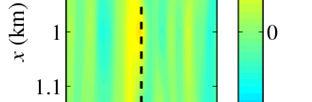
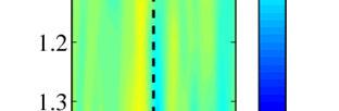
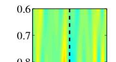
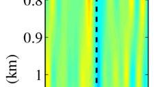
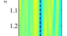
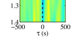
7 coefficient between two waves is given by: COASTAL ENGINEERING < A( t) η L( t+ τ ) > R( τ ) = (1) σ σ 2 A η L where A(t) and η L (t) are the wave profiles of the enveloped waves for the short waves and the long waves, respectively. The brackets <> indicate the ensemble-averaged value for time (t). σ A2 and σ ηl are the standard deviations for the enveloped waves for the short waves and the long waves, respectively. A negative correlation can be observed from x = 0.6 km up to x = 1.4 km at τ = 0.0 s on the ridge (y = 0.2 to 0.4 km). On the other hand, the cross-correlation coefficient along τ = 0.0 s is essentially inverted close to the shoreline in comparison to the offshore situation from y = 0.8 to 0.2 km. Offshore, the long waves are negatively correlated with the enveloped waves for the short waves at τ = 0.0 s, while the cross-correlation coefficient at near-zero time lags is dominantly positive in the near shore region. Kashima and Hirayama (2010), List (1992) and Janssen and Battjes (2003) reported in unidirectional irregular wave experiments that the long waves are negatively correlated with the enveloped waves for the short waves and that long waves bound in wave grouping including the short waves are generated offshore, but the cross-correlation coefficient between two waves is dominantly positive in the surf zone and near shore region. This means that the long waves bound in wave grouping are released in the wave breaking process and the free long waves propagate in the surf zone. Thus the behavior of the long waves in this experiment can be summarized as follows. First, on the mild slope side (y = 0.3 to 0.2 km), the long waves are negatively correlated with the enveloped waves for the short waves and the long waves bound in wave grouping are remarkably generated in front of the submerged and detached breakwaters. Thus, it is supposed that long waves bound in wave grouping are released due to the wave breaking behind the submerged and detached breakwaters because the profile of the long waves almost matched that of the enveloped waves for the short waves. These results closely correspond to the results of unidirectional irregular wave experiments by List (1992) and Kashima and Hirayama (2010), and imply that unidirectional long waves are generated in front of the seawall. Second, on the steep slope side (y = 0.8 to 0.4 km), the behavior of the long waves is similar to that on the mild slope side (y = 0.3 to 0.2 km) in front of the submerged and detached breakwaters. It is also expected that the long waves bound in wave grouping are released due to the wave breaking behind the submerged and detached breakwaters, the same as the results on the mild slope side, but there are significant differences between the two waves in terms of their amplitudes and phases. Therefore, there is a clear difference between the behavior of the long waves on the mild slope side and on the steep slope side. In order to check the behavior of the long waves in front of the seawall in detail, Fig. 8 shows the spectra of the water surface elevation and two-directional fluid velocities. The horizontal axis is the frequency (f) and the vertical axis is the energy density of water surface elevation and two-directional fluid velocities (S η, S u and S v ), respectively. The vertical dashed line indicates the boundary frequency (1/30 Hz) between the short and long waves. First, the energy density of the long waves is smaller (i.e., S η = Ο(10 1 )) and the energy density of the fluid velocity along the shore for the long waves is larger (a) y = -0.8 km (b) y = -0.6 km (c) y = -0.4 km (d) y = -0.2 km (e) y = 0 km (f) y = 0.2 km (g) y = 0.4 km Figure 7. Spatial variations of the cross-correlation coefficient between the long waves and the enveloped waves (color contour: cross-correlation coefficient, vertical dashed line: τ = 0 s, horizontal dotted line from y = 0.8 to 0.2 km: location of the submerged and detached breakwaters)
8 8 COASTAL ENGINEERING 2012 y=-0.7km y=-0.2km y=-0.8km y=-0.3km y=-0.4km y=-0.9km y=-0.6km y=-0.5km (a) Water surface elevation y=-0.4km y=-0.2km y=-0.3km y=-0.9km y=-0.7km y=-0.5km y=-0.6km y=-0.8km (b) Along-shore fluid velocity y=-0.7km y=-0.6km y=-0.5km y=-0.9km y=-0.3km y=-0.2km y=-0.4km y=-0.8km (c) Cross-shore fluid velocity Figure 8. Spectra of water surface elevation and fluid velocity in front of seawall
 release of bound long wave due to coastal structures (cross) steady wave -1.0-0.9-0.8-0.7-0.6-0.5-0.4-0.3-0.2-0.1 0.0 y (km) 0.5 0 (m) Figure 9.")
9 COASTAL ENGINEERING Cross-shore long wave bound in wave grouping Node Cross-shore long wave bound in wave grouping Release of bound long wave by refraction of short waves Along-shore and cross-shore long (along) release of bound long wave due to coastal structures (cross) steady wave y (km) (m) Figure 9. Behavior of long waves in front of seawall (contour: long wave height) (i.e., S v = Ο(10 2 )) near y = 0.3 km. These results indicate the existence of a standing long wave along the shore which has a node at y = 0.3 km. However, the energy density of the cross-shore fluid velocity for the long waves is extremely small. The reason for this is thought to be that the waves with wave grouping refract on the sharply changing coastal bathymetry around y = 0.3 to 0.2 km and the free long waves released from wave groupings propagate along the shore. These results are supported by the finding that the phase of the long waves is in good agreement with one of the enveloped waves for the short waves as shown in the previous section. Thus, it is estimated that the along-shore long waves are generated on the mild slope side around y = 0.3 to 0.2 km. Second, on the steep slope side around y = 0.8 to 0.4 km, the energy densities of both two-directional fluid velocities for the long waves are large (i.e., S u and S v = Ο(10 1 ) to Ο(10 2 )). It is estimated that not only the along-shore long waves but also the cross-shore long waves based on the short waves from offshore are generated simultaneously. This result is supported by the finding that even though the phases of the enveloped waves for the short waves from y = 0.8 to 0.4 km mutually correspond among each measurement point, there is a significant difference in profile between the long waves and enveloped waves for the short waves. Therefore, the long waves on the steep slope side are generated by the superposition between the along-shore and cross-shore long waves spatially. The behavior of the long waves in front of the seawall is summarized in Fig. 9. Effective Countermeasures for Wave Overtopping In the previous section, we investigated the characteristics of wave transformation and wave overtopping around the damaged area. In particular, it was supposed that the generated long waves and wave set-up on the steep slope side and the increase of the short waves due to the local wave concentration on the mild slope side have adverse influences on the increase of wave overtopping. This section examines the effects of countermeasures for wave overtopping based on the above characteristics. Two types of countermeasure were selected to evaluate their effect on reducing the wave overtopping rate. One was an impermeable jetty installed at the border between the mild and steep slope sides (y = 0.3 km), with dimensions of 194 m long, 11.0 m wide and 3.0 m high above the still water level (Fig. 10(a)). The water depth at the head of the jetty is 20.0 m. The jetty is expected to control the long waves which propagate along the shore from the mild to steep slope side. The other countermeasure is two impermeable submerged breakwaters installed at the depth of 20.0 m on the mild and steep slope sides at a little distance from the seawall, with dimensions of 117 m long, 45.0 m wide and 5.0 m deep below the still water level (Fig. 10(b)). These submerged breakwaters are expected to control the wave concentration set-up of the short waves propagating from offshore. Fig. 11 shows the characteristics of the wave transformation in front of the seawall and the wave overtopping rate for the two types of countermeasure. The open and filled circles indicate the data without and with each countermeasure, respectively. Fig. 11(a) shows that the wave overtopping rate at y = 0.3 km decreases with decreasing short and long wave height, and variation of wave set-up by placing the jetty because of the shielding effect of the jetty. On the other hand, the wave overtopping rate at y = 0.2 km increases because of the reflected waves at the jetty. Moreover, the long wave
10 10 COASTAL ENGINEERING L=194m, B=11m, H=D.L.+3.0m 1.3 L=117m, B=45m, H=D.L.-5.0m x (km) 1.5 x (km) y (km) y (km) Submerged breakwater jetty Existing detached breakwater (a) Jetty (b) Submerged breakwater Figure 10. Location of countermeasures for wave overtopping heights and variations of wave set-up decrease from 0.3 to 1.0 m and from 0.1 to 0.5 m on the steep slope side around y = 0.7 to 0.4 km by placing the jetty, respectively. However, as the distance from the jetty increases, its reduction effects gradually decreases and one of the wave overtopping rates is approximately 5 % in the most severely damaged area (y = 0.8 km). These results imply that the jetty may control the behavior of long waves along the seawall, but the range of reduction effect is limited to the area surrounding the jetty. On the other hand, the wave overtopping rate decreases substantially in the most severely damaged area due to the decreased wave set-up as shown in Fig. 10(b), although there is little difference between the short and long wave heights with and without the two submerged breakwaters around y = 0.7 to 0.5 km. The effect of the submerged breakwaters on reducing wave overtopping rate is approximately 30 % in the most severely damaged area. CONCLUSIONS In this study, model experiments were conducted by using a large basin to investigate the mechanism and countermeasures of wave overtopping for long-period swells at the Shimoniikawa Coast. The main conclusions are as follows: 1. Long waves induced by wave groupings and wave set-up affect wave overtopping on the steep slope side and short waves with wave groupings affect wave overtopping on the mild slope side. 2. It is possible to decrease wave overtopping discharges of long-period swells by placing a jetty or some submerged breakwaters to control along-shore long waves in front of a seawall or short waves with wave groupings propagating from offshore. 3. When discussing countermeasures for wave overtopping of long-period swells, it is important to consider the effects on not only short waves but also long waves and wave set-up. ACKNOWLEDGMENTS This research was partially supported by the Japan Railway Construction, Transport and Technology Agency. REFERENCES Fukase, Y., R. Suminda, Y. Tajima and S. Satoh Deformation of long-period giant waves on the Shimoniikawa coast, Journal of JSCE, Ser. B2 (Coastal Engineering), Vol.65, (in Japanese).
11 COASTAL ENGINEERING (a) Jetty (b) Submerged breakwater Figure 11. Reduction effects of countermeasures (H S: short wave height, H L: long wave height, η bar: mean water surface elevation rising, q: wave overtopping rate (upper: log value, lower: normal value)) Fukase, Y., R. Suminda, Y. Tajima and S. Satoh Mechanism and countermeasures for local amplification of long period waves due to alongshore change in nearshore bathymetry, Journal of JSCE, Ser. B2 (Coastal Engineering), Vol.66, (in Japanese). Hirayama, K., H. Kashima and T. Hiraishi Examples of unexpected high waves in shallow water in Japan, Proceedings of Rogue Waves 2008, Hirayama, K., H. Kashima and K. Nakai A study on characteristics of long period swell spectrum and its grouping, Annual Journal of Civil Engineering in the Ocean, JSCE, Vol.25, (in Japanese). Janssen, T. T. and J. A. Battjes Long waves induced by short-wave groups over a sloping bottom, Journal of Geophysical Research, Vol.108, C8, 14 pp. Kashima, H., K. Hirayama, T. Hiraishi and K. Shimizu. 2009, Estimation of encounter timing of swell by using nationwide wave observation system (NOWPHAS), Technical Note of The Port and Airport Research Institute, No.1191, 21 pp. (in Japanese). Kashima, H. and K. Hirayama Effects of bottom topography characteristics on transformations of long period swell, in: Proceedings of the 4th SCACR - International Short Conference on Applied Coastal Research, ISBN Barcelona, Spain.
12 12 COASTAL ENGINEERING 2012 Kashima, H. and K. Hirayama. 2010, Experiments on wave overtopping rate and wave pressure on seawalls of long period swell, Technical Note of The Port and Airport Research Institute, No.1218, 26 pp. (in Japanese). Kawasaki, K., N. Mizutani, K. Iwata, T. Kobayashi, M. Yuhi, T. Saitoh, T. Kitano, H. Sumi, H. Mase and T. Yasuda Field survey of damage due to February 2008 high wave on east coast of Toyama Prefecture, Annual Journal of Coastal Engineering, JSCE, Vol.55, (in Japanese). Tajima, Y., H. Ishizashi and S. Satoh Concentration of slowly-varying nearshore waves and currents around the edge of two different bottom slopes, Journal of JSCE, Ser. B2 (Coastal Engineering), Vol.65, (in Japanese). List, J.H Wave groupiness variation in the nearshore, Coastal Engineering, Vol.15,
IMAGE-BASED FIELD OBSERVATION OF INFRAGRAVITY WAVES ALONG THE SWASH ZONE. Yoshimitsu Tajima 1
 IMAGE-BASED FIELD OBSERVATION OF INFRAGRAVITY WAVES ALONG THE SWASH ZONE Yoshimitsu Tajima 1 This study develops an image-based monitoring techniques for observations of surf zone hydrodynamics especially
PROPAGATION OF LONG-PERIOD WAVES INTO AN ESTUARY THROUGH A NARROW INLET
 PROPAGATION OF LONG-PERIOD WAVES INTO AN ESTUARY THROUGH A NARROW INLET Takumi Okabe, Shin-ichi Aoki and Shigeru Kato Department of Civil Engineering Toyohashi University of Technology Toyohashi, Aichi,
LOCALLY CONCENTRATED SEVERE BEACH EROSION ON SEISHO COAST CAUSED BY TYPHOON T0709
 F-4 Fourth International Conference on Scour and Erosion 2008 LOCALLY CONCENTRATED SEVERE BEACH EROSION ON SEISHO COAST CAUSED BY TYPHOON T0709 Yoshimitsu TAJIMA 1 and Shinji SATO 2 1 Member of JSCE, Associate
LABORATORY EXPERIMENTS ON WAVE OVERTOPPING OVER SMOOTH AND STEPPED GENTLE SLOPE SEAWALLS
 Asian and Pacific Coasts 23 LABORATORY EXPERIMENTS ON WAVE OVERTOPPING OVER SMOOTH AND STEPPED GENTLE SLOPE SEAWALLS Takayuki Suzuki 1, Masashi Tanaka 2 and Akio Okayasu 3 Wave overtopping on gentle slope
Wave Breaking and Wave Setup of Artificial Reef with Inclined Crown Keisuke Murakami 1 and Daisuke Maki 2
 Wave Breaking and Wave Setup of Artificial Reef with Inclined Crown Keisuke Murakami 1 and Daisuke Maki 2 Beach protection facilities are sometimes required to harmonize with coastal environments and utilizations.
STUDY ON TSUNAMI PROPAGATION INTO RIVERS
 ABSTRACT STUDY ON TSUNAMI PROPAGATION INTO RIVERS Min Roh 1, Xuan Tinh Nguyen 2, Hitoshi Tanaka 3 When tsunami wave propagation from the narrow river mouth, water surface is raised and fluctuated by long
LIFE TIME OF FREAK WAVES: EXPERIMENTAL INVESTIGATIONS
 Proceedings of the 6 th International Conference on the Application of Physical Modelling in Coastal and Port Engineering and Science (Coastlab16) Ottawa, Canada, May 10-13, 2016 Copyright : Creative Commons
Wave Setup at River and Inlet Entrances Due to an Extreme Event
 Proceedings of International Conference on Violent Flows (VF-2007) Organized by RIAM, Kyushu University, Fukuoka, Japan Wave Setup at River and Inlet Entrances Due to an Extreme Event Xuan Tinh Nguyen
AN EXPERIMENTAL STUDY OF REGULAR LONG CRESTED WAVES OVER A CRESCENT TYPE SHOAL
 Journal of Marine Science and Technology, Vol., No., pp. - () DOI:./JMST--- AN EXPERIMENTAL STUDY OF REGULAR LONG CRESTED WAVES OVER A CRESCENT TYPE SHOAL Wen-Kai Weng, Jaw-Guei Lin, and Chun-Sien Hsiao
MODELING OF CLIMATE CHANGE IMPACTS ON COASTAL STRUCTURES - CONTRIBUTION TO THEIR RE-DESIGN
 Proceedings of the 14 th International Conference on Environmental Science and Technology Rhodes, Greece, 3-5 September 2015 MODELING OF CLIMATE CHANGE IMPACTS ON COASTAL STRUCTURES - CONTRIBUTION TO THEIR
Numerical modeling of refraction and diffraction
 Numerical modeling of refraction and diffraction L. Balas, A. inan Civil Engineering Department, Gazi University, Turkey Abstract A numerical model which simulates the propagation of waves over a complex
VARIATIONS OF STATISTICS FOR RANDOM WAVES PROPAGATING OVER A BAR
 864 Journal of Marine Science and Technology, Vol. 3, No. 6, pp. 864-869 (015) DOI: 1119/JMST-015-0610-3 VARIATIONS OF STATISTICS FOR RANDOM WAVES PROPAGATING OVER A BAR Yu-Xiang Ma, Xiao-Zhou Ma, and
WIND SPEED LENGTH OF TIME WIND BLOWS (Duration) DISTANCE OVER WHICH IT BLOWS (Fetch)
 DISTANCE OVER WHICH IT BLOWS (Fetch)") WAVES Up and down movement of ocean surface Transportation of energy across the water over vast distances If not stopped by anything, waves can travel entire oceans Size and speed depend upon: WIND SPEED
WAVES Up and down movement of ocean surface Transportation of energy across the water over vast distances If not stopped by anything, waves can travel entire oceans Size and speed depend upon: WIND SPEED
A New Generator for Tsunami Wave Generation
 Journal of Energy and Power Engineering 10 (2016) 166-172 doi: 10.17265/1934-8975/2016.03.004 D DAVID PUBLISHING Tetsuya Hiraishi 1, Ryokei Azuma 1, Nobuhito Mori 2, Toshihiro Yasuda 2 and Hajime Mase
LABORATORY STUDY ON TSUNAMI REDUCTION EFFECT OF TEIZAN CANAL
 Proceedings of the 6 th International Conference on the Application of Physical Modelling in Coastal and Port Engineering and Science (Coastlab16) Ottawa, Canada, May 10-13, 2016 Copyright : Creative Commons
Directional Wave Spectra from Video Images Data and SWAN Model. Keywords: Directional wave spectra; SWAN; video images; pixels
 Jurnal Teknologi Full paper Directional Wave Spectra from Video Images Data and SWAN Model Muhammad Zikra a*, Noriaki Hashimoto b, Masaru Yamashiro b, Kojiro Suzuki c a Department of Ocean Engineering,
WAVE LOAD ACTING ON HORIZONTAL PLATE DUE TO BORE
 Proceedings of the 6 th International Conference on the Application of Physical Modelling in Coastal and Port Engineering and Science (Coastlab16) Ottawa, Canada, May 10-13, 2016 Copyright : Creative Commons
PUV Wave Directional Spectra How PUV Wave Analysis Works
 PUV Wave Directional Spectra How PUV Wave Analysis Works Introduction The PUV method works by comparing velocity and pressure time series. Figure 1 shows that pressure and velocity (in the direction of
SUPERGEN Wind Wind Energy Technology Rogue Waves and their effects on Offshore Wind Foundations
 SUPERGEN Wind Wind Energy Technology Rogue Waves and their effects on Offshore Wind Foundations Jamie Luxmoore PhD student, Lancaster University SUPERGEN Wind II - 7 th training seminar 3 rd - 4 th September
ABNORMALLY HIGH STORM WAVES OBSERVED ON THE EAST COAST OF KOREA
 ABNORMALLY HIGH STORM WAVES OBSERVED ON THE EAST COAST OF KOREA WEON MU JEONG 1 ; SANG-HO OH ; DONGYOUNG LEE 3 ; KYUNG-HO RYU 1 Coastal Engineering Research Department, Korea Ocean Research and Development
IMAGE-BASED STUDY OF BREAKING AND BROKEN WAVE CHARACTERISTICS IN FRONT OF THE SEAWALL
 IMAGE-BASED STUDY OF BREAKING AND BROKEN WAVE CHARACTERISTICS IN FRONT OF THE SEAWALL Weijie Liu 1 and Yoshimitsu Tajima 1 This study aims to study the breaking and broken wave characteristics in front
Yasuyuki Hirose 1. Abstract
 Study on Tsunami force for PC box girder Yasuyuki Hirose 1 Abstract In this study, a waterway experiment was performed in order to understand the influence of tsunami forms on tsunami forces acting on
LABORATORY EXPERIMENTS ON EROSION CONTROL PERFORMANCE OF AN L- SHAPED PERMEABLE STRUCTURE. Abstract
 LABORATORY EXPERIMENTS ON EROSION CONTROL PERFORMANCE OF AN L- SHAPED PERMEABLE STRUCTURE Yuuji Maeda 1, Masayuki Unno 2, Masafumi Sato 2, Takao Kurita 2, Takaaki Uda 3 and Shinji Sato 4 Abstract A new
PHYSICAL AND NUMERICAL MODELLING OF WAVE FIELD IN FRONT OF THE CONTAINER TERMINAL PEAR - PORT OF RIJEKA (ADRIATIC SEA)
") PHYSICAL AND NUMERICAL MODELLING OF WAVE FIELD IN FRONT OF THE CONTAINER TERMINAL PEAR - PORT OF RIJEKA (ADRIATIC SEA) DALIBOR CAREVIĆ (1), GORAN LONČAR (1), VLADIMIR ANDROČEC (1) & MARIN PALADIN (1) 1.
PHYSICAL AND NUMERICAL MODELLING OF WAVE FIELD IN FRONT OF THE CONTAINER TERMINAL PEAR - PORT OF RIJEKA (ADRIATIC SEA) DALIBOR CAREVIĆ (1), GORAN LONČAR (1), VLADIMIR ANDROČEC (1) & MARIN PALADIN (1) 1.
THE WAVE CLIMATE IN THE BELGIAN COASTAL ZONE
 THE WAVE CLIMATE IN THE BELGIAN COASTAL ZONE Toon Verwaest, Flanders Hydraulics Research, toon.verwaest@mow.vlaanderen.be Sarah Doorme, IMDC, sarah.doorme@imdc.be Kristof Verelst, Flanders Hydraulics Research,
ABSTRACT. KEY WORDS: coral reef, storm waves, infragravity waves, power plant, cooling water, field observation. INTRODUCTION FIELD OBSERVATION
 M.W.L. Fluctuations Inside a Cooling Water Tank Set Inside a Coral Reef Julio Monroy Department of Civil Engineering, Kagoshima University -2-4 Korimoto, Kagoshima-shi, Japan 89-65 Ryuchiro Nishi, Michio
Low-crested offshore breakwaters: a functional tool for beach management
 Environmental Problems in Coastal Regions VI 237 Low-crested offshore breakwaters: a functional tool for beach management K. Spyropoulos & E. Andrianis TRITON Consulting Engineers, Greece Abstract Beach
INVESTIGATION OF WAVE AGITATION INSIDE THE NEW FISHERY PORT (CASE STUDY: NEW MRZOUKA FISHERY PORT, LIBYA)
") INVESTIGATION OF WAVE AGITATION INSIDE THE NEW FISHERY PORT (CASE STUDY: NEW MRZOUKA FISHERY PORT, LIBYA) Abdelazim M. Ali Researcher, The Hydraulics Research Institute, National Water Research Center,
INVESTIGATION OF WAVE AGITATION INSIDE THE NEW FISHERY PORT (CASE STUDY: NEW MRZOUKA FISHERY PORT, LIBYA) Abdelazim M. Ali Researcher, The Hydraulics Research Institute, National Water Research Center,
OECS Regional Engineering Workshop September 29 October 3, 2014
 B E A C H E S. M A R I N A S. D E S I G N. C O N S T R U C T I O N. OECS Regional Engineering Workshop September 29 October 3, 2014 Coastal Erosion and Sea Defense: Introduction to Coastal Dynamics David
Wave Propagation and Shoaling
 Wave Propagation and Shoaling Focus on movement and natural alteration of the characteristics of waves as they travel from the source region toward shore Waves moving from deep to intermediate/shallow
IMPACTS OF COASTAL PROTECTION STRATEGIES ON THE COASTS OF CRETE: NUMERICAL EXPERIMENTS
 IMPACTS OF COASTAL PROTECTION STRATEGIES ON THE COASTS OF CRETE: NUMERICAL EXPERIMENTS Tsanis, I.K., Saied, U.M., Valavanis V. Department of Environmental Engineering, Technical University of Crete, Chania,
INTRODUCTION TO COASTAL ENGINEERING AND MANAGEMENT
 Advanced Series on Ocean Engineering Volume 16 INTRODUCTION TO COASTAL ENGINEERING AND MANAGEMENT J. William Kamphuis Queen's University, Canada World Scientific Singapore New Jersey London Hong Kong Contents
LONG WAVE EFFECTS ON BREAKING WAVES OVER FRINGING REEFS
 LONG WAVE EFFECTS ON BREAKING WAVES OVER FRINGING REEFS John T. Goertz 1, James M. Kaihatu, Alex Sheremet 3, Ernest R. Smith 4 and Jane M. Smith 5 Modeling of wave energy transformation and breaking on
LABORATORY EXPERIMENTS FOR WAVE RUN-UP ON THE TETRAPOD ARMOURED RUBBLE MOUND STRUCTURE WITH A STEEP FRONT SLOPE
 Proceedings of the 6 th International Conference on the Application of Physical Modelling in Coastal and Port Engineering and Science (Coastlab16) Ottawa, Canada, May 10-13, 2016 Copyright : Creative Commons
SORTING AND SELECTIVE MOVEMENT OF SEDIMENT ON COAST WITH STEEP SLOPE- MASUREMENTS AND PREDICTION
 SORTING AND SELECTIVE MOVEMENT OF SEDIMENT ON COAST WITH STEEP SLOPE- MASUREMENTS AND PREDICTION Toshiro San-nami 1, Takaaki Uda 2, Masumi Serizawa 1 and Toshinori Ishikawa 2 Conveyer belts carrying gravel
COMPARISON OF ROCK SEAWALL AND DUNE FOR STORM DAMAGE REDUCTION
 COMPARISON OF ROCK SEAWALL AND DUNE FOR STORM DAMAGE REDUCTION Hyun Dong Kim 1, Nobuhisa Kobayashi 2, and Xavier Chávez Cárdenas 3 Four test series consisting of 14 tests and 140 runs (each run lasted
Currents measurements in the coast of Montevideo, Uruguay
 Currents measurements in the coast of Montevideo, Uruguay M. Fossati, D. Bellón, E. Lorenzo & I. Piedra-Cueva Fluid Mechanics and Environmental Engineering Institute (IMFIA), School of Engineering, Research
Shoreline Evolution Due to Oblique Waves in Presence of Submerged Breakwaters. Nima Zakeri (Corresponding Author), Mojtaba Tajziehchi
, Mojtaba Tajziehchi") Shoreline Evolution Due to Oblique Waves in Presence of Submerged Breakwaters Nima Zakeri (Corresponding Author), Mojtaba Tajziehchi Department of Civil Engineering, Faculty of Engineering, University
Shoreline Evolution Due to Oblique Waves in Presence of Submerged Breakwaters Nima Zakeri (Corresponding Author), Mojtaba Tajziehchi Department of Civil Engineering, Faculty of Engineering, University
Tsunami Force Reduction due to Obstacle in Front of Coastal Dike and Evaluation of Collision Force by Driftage
 Journal of Energy and Power Engineering 11 (2017) 300-310 doi: 10.17265/1934-8975/2017.05.003 D DAVID PUBLISHING Tsunami Force Reduction due to Obstacle in Front of Coastal Dike and Evaluation of Collision
Sea State Analysis. Topics. Module 7 Sea State Analysis 2/22/2016. CE A676 Coastal Engineering Orson P. Smith, PE, Ph.D.
 Sea State Analysis Module 7 Orson P. Smith, PE, Ph.D. Professor Emeritus Module 7 Sea State Analysis Topics Wave height distribution Wave energy spectra Wind wave generation Directional spectra Hindcasting
PREDICTION OF BEACH CHANGES AROUND ARTIFICIAL REEF USING BG MODEL
 PREDICTION OF BEACH CHANGES AROUND ARTIFICIAL REEF USING BG MODEL Hiroaki Fujiwara 1, Takaaki Uda 2, Toshiaki Onishi 1, Shiho Miyahara 3 and Masumi Serizawa 3 On the Kaike coast, one of the twelve detached
Nearshore Placed Mound Physical Model Experiment
 Nearshore Placed Mound Physical Model Experiment PURPOSE: This technical note describes the migration and dispersion of a nearshore mound subjected to waves in a physical model. The summary includes recommendations
Study of Passing Ship Effects along a Bank by Delft3D-FLOW and XBeach1
 Study of Passing Ship Effects along a Bank by Delft3D-FLOW and XBeach1 Minggui Zhou 1, Dano Roelvink 2,4, Henk Verheij 3,4 and Han Ligteringen 2,3 1 School of Naval Architecture, Ocean and Civil Engineering,
Appendix E Cat Island Borrow Area Analysis
 Appendix E Cat Island Borrow Area Analysis ERDC/CHL Letter Report 1 Cat Island Borrow Area Analysis Multiple borrow area configurations were considered for Cat Island restoration. Borrow area CI1 is located
Determination of Nearshore Wave Conditions and Bathymetry from X-Band Radar Systems
 Determination of Nearshore Wave Conditions and Bathymetry from X-Band Radar Systems Okey G. Nwogu Dept. of Naval Architecture and Marine Engineering University of Michigan Ann Arbor, MI 48109 Phone: (734)
SAND BOTTOM EROSION AND CHANGES OF AN ACTIVE LAYER THICKNESS IN THE SURF ZONE OF THE NORDERNEY ISLAND
 SAND BOTTOM EROSION AND CHANGES OF AN ACTIVE LAYER THICKNESS IN THE SURF ZONE OF THE NORDERNEY ISLAND Kos'yan R. 1, Kunz H. 2, Podymov l. 3 1 Prof.Dr.,The Southern Branch of the P.P.Shirshov Institute
The History of Coastal Flood Hazard Assessments in the Great Lakes
 The History of Coastal Flood Hazard Assessments in the Great Lakes Brian A. Caufield, P.E., CFM June 23, 2016 2 The Great Lakes Some Statistics Courtesy of Great Lakes Information Network One-fifth of
MULTIDECADAL SHORELINE EVOLUTION DUE TO LARGE-SCALE BEACH NOURISHMENT JAPANESE SAND ENGINE? Abstract
 MULTIDECADAL SHORELINE EVOLUTION DUE TO LARGE-SCALE BEACH NOURISHMENT JAPANESE SAND ENGINE? Masayuki Banno 1, Satoshi Takewaka 2 and Yoshiaki Kuriyama 3 Abstract Beach nourishment is one of the countermeasures
Determination Of Nearshore Wave Conditions And Bathymetry From X-Band Radar Systems
 Determination Of Nearshore Wave Conditions And Bathymetry From X-Band Radar Systems Okey G. Nwogu Dept. of Naval Architecture and Marine Engineering University of Michigan Ann Arbor, MI 489 phone: (734)
ESTIMATION OF TSUNAMI FORCE ACTING ON THE BLOCK ARMORED BREAKWATER DUE TO SOLITON FISSION
 ESTMATON OF TSUNAM FORCE ACTNG ON THE BLOCK ARMORED BREAKWATER DUE TO SOLTON FSSON Sohei Maruyama 1, Tomotsuka Takayama 2, Kenichiro Shimosako 3, Akihiko Yahiro 2, Kojiro Suzuki 3, Toru Aota 1, Masashi
An experimental study of internal wave generation through evanescent regions
 An experimental study of internal wave generation through evanescent regions Allison Lee, Julie Crockett Department of Mechanical Engineering Brigham Young University Abstract Internal waves are a complex
Chapter 10 Waves. wave energy NOT the water particles moves across the surface of the sea. wave form moves and with it, energy is transmitted
 Capillary Waves, Wind Waves, Chapter 10 Waves Anatomy of a Wave more like a real wave Tsunamis, Internal waves big waves huge waves rogue waves small waves more like a sine wave Wave direction Wave wave
WAVE PROPAGATION ON A FLUME: PHYSICAL MODELLING
 WAVE PROPAGATION ON A FLUME: PHYSICAL MODELLING J. M. P. Conde a,b,c, R. Reis b, C. J. Fortes b, and D. R. C. B. Neves b a Universidade Nova de Lisboa Faculty of Science and Technology Dep. Mechanical
Deep-water orbital waves
 What happens when waves approach shore? Deep-water orbital waves Fig. 9.16, p. 211 Wave motion is influenced by water depth and shape of the shoreline wave buildup zone surf zone beach Wave base deepwater
Undertow - Zonation of Flow in Broken Wave Bores
 Nearshore Circulation Undertow and Rip Cells Undertow - Zonation of Flow in Broken Wave Bores In the wave breaking process, the landward transfer of water, associated with bore and surface roller decay
EXPERIMENTAL RESEARCH ON COEFFICIENT OF WAVE TRANSMISSION THROUGH IMMERSED VERTICAL BARRIER OF OPEN-TYPE BREAKWATER
 EXPERIMENTAL RESEARCH ON COEFFICIENT OF WAVE TRANSMISSION THROUGH IMMERSED VERTICAL BARRIER OF OPEN-TYPE BREAKWATER Liehong Ju 1, Peng Li,Ji hua Yang 3 Extensive researches have been done for the interaction
MAR 110 LECTURE #15 Wave Hazards
 1 MAR 110 LECTURE #15 Wave Hazards Rogue Wave Hazard Rogue waves are very large open ocean waves of sometimes can range in height from 60 ft (20m) to120 feet (40m) and thus a significant hazard to large
2. Water levels and wave conditions. 2.1 Introduction
 18 2. Water levels and wave conditions 2.1 Introduction This Overtopping Manual has a focus on the aspects of wave run-up and wave overtopping only. It is not a design manual, giving the whole design process
Appendix D: SWAN Wave Modelling
 Appendix D: SWAN Wave Modelling D.1 Preamble The Eurobodalla Shire Council area is subject to extreme waves originating from offshore storms. When swell waves approach the coast, they are modified by the
OCEAN WAVES NAME. I. Introduction
 NAME OCEAN WAVES I. Introduction The physical definition of a wave is a disturbance that transmits energy from one place to another. In the open ocean waves are formed when wis blowing across the water
Wave Induced Flow around Submerged Sloping Plates
 CHAPTER 105 Wave Induced Flow around Submerged Sloping Plates Hitoshi Murakami 1, Sadahiko Itoh 2, Yoshihiko Hosoi 3 and Yoshiyuki Sawamura 4 Abstract This paper deals with the hydraulic characteristics
Wave Energy Atlas in Vietnam
 Wave Energy Atlas in Vietnam Nguyen Manh Hung, Duong Cong Dien 1 1 Institute of Mechanics, 264 Doi Can Str. Hanoi, Vietnam nmhungim@gmail.com; duongdienim@gmail.com Abstract Vietnam has achieved remarkable
USE OF X-BAND RADAR FOR WAVE AND BEACH MORPHOLOGY ANALYSIS
 USE OF X-BAND RADAR FOR WAVE AND BEACH MORPHOLOGY ANALYSIS JAE HYENG LEE ECOH Corporation, 2-6-4, Kitaueno, Taito, Tokyo, 110-0014, Japan SATOSHI TAKEWAKA Institute of Engineering Mechanics and Systems,
Comparison of data and model predictions of current, wave and radar cross-section modulation by seabed sand waves
 Comparison of data and model predictions of current, wave and radar cross-section modulation by seabed sand waves Cees de Valk, ARGOSS Summary SAR Imaging of seabed features Seabed Sand waves Objectives
PREDICTION OF FUTURE SHORELINE CHANGE WITH SEA-LEVEL RISE AND WAVE CLIMATE CHANGE AT HASAKI, JAPAN
 PREDICTION OF FUTURE SHORELINE CHANGE WITH SEA-LEVEL RISE AND WAVE CLIMATE CHANGE AT HASAKI, JAPAN Masayuki Banno 1 and Yoshiaki Kuriyama 1 We developed a shoreline change model considering the effects
Tedious Creek Small Craft Harbor: CGWAVE Model Comparisons Between Existing and Authorized Breakwater Configurations
 Tedious Creek Small Craft Harbor: CGWAVE Model Comparisons Between Existing and Authorized Breakwater Configurations by Michael J. Briggs, Barbara P. Donnell, Zeki Demirbilek, and Robert D. Carver PURPOSE:
EFFECTS OF WAVE, TIDAL CURRENT AND OCEAN CURRENT COEXISTENCE ON THE WAVE AND CURRENT PREDICTIONS IN THE TSUGARU STRAIT
 EFFECTS OF WAVE, TIDAL CURRENT AND OCEAN CURRENT COEXISTENCE ON THE WAVE AND CURRENT PREDICTIONS IN THE TSUGARU STRAIT Ayumi Saruwatari 1, Yoshihiro Yoneko 2 and Yu Tajima 3 The Tsugaru Strait between
PARAMETRIZATION OF WAVE TRANSFORMATION ABOVE SUBMERGED BAR BASED ON PHYSICAL AND NUMERICAL TESTS
 Proceedings of the 6 th International Conference on the Application of Physical Modelling in Coastal and Port Engineering and Science (Coastlab16) Ottawa, Canada, May 10-13, 2016 Copyright : Creative Commons
Bay County, MI Coastal Hazard Analysis Flood Risk Review Meeting. May 14, 2018
 Bay County, MI Coastal Hazard Analysis Flood Risk Review Meeting May 14, 2018 Agenda Introductions Coastal Flood Risk Study and Mapping Program Current Status Technical Overview of Study and Mapping Floodplain
Undertow - Zonation of Flow in Broken Wave Bores
 Lecture 22 Nearshore Circulation Undertow - Zonation of Flow in Broken Wave Bores In the wave breaking process, the landward transfer of water, associated with bore and surface roller decay within the
Technical Brief - Wave Uprush Analysis Island Harbour Club, Gananoque, Ontario
 Technical Brief - Wave Uprush Analysis RIGGS ENGINEERING LTD. 1240 Commissioners Road West Suite 205 London, Ontario N6K 1C7 October 31, 2014 Table of Contents Section Page Table of Contents... i List
CHAPTER 134 INTRODUCTION
 CHAPTER 134 NEW JETTIES FOR TUNG-KANG FISHING HARBOR, TAIWAN Chi-Fu Su Manager Engineering Department Taiwan Fisheries Consultants, Inc. Taipei, Taiwan INTRODUCTION Tung-Kang Fishing Harbor, which is about
A Preliminary Review of Beach Profile and Hardbottom Interactions
 A Preliminary Review of Beach Profile and Hardbottom Interactions Douglas W. Mann, P.E., D.CE. CB&I A World of Solutions Presentation Goal Lead to a better understanding of the challenges regarding the
Waves. G. Cowles. General Physical Oceanography MAR 555. School for Marine Sciences and Technology Umass-Dartmouth
 Waves G. Cowles General Physical Oceanography MAR 555 School for Marine Sciences and Technology Umass-Dartmouth Waves Sound Waves Light Waves Surface Waves Radio Waves Tidal Waves Instrument Strings How
MODEL EXPERIMENT AND FIELD TEST OF PW-OWC TYPE WAVE POWER EXTRACTING BREAKWATER
 MODEL EXPERIMENT AND FIELD TEST OF PW-OWC TYPE WAVE POWER EXTRACTING BREAKWATER Kenichiro Shimosako 1, Taro Arikawa 2, Masahide Takeda 3, Kazuyoshi Kihara 4, Yasushi Hosokawa 5, Takayuki Fueki 6, Koichi
COMPARISON OF DEEP-WATER ADCP AND NDBC BUOY MEASUREMENTS TO HINDCAST PARAMETERS. William R. Dally and Daniel A. Osiecki
 COMPARISON OF DEEP-WATER ADCP AND NDBC BUOY MEASUREMENTS TO HINDCAST PARAMETERS William R. Dally and Daniel A. Osiecki Surfbreak Engineering Sciences, Inc. 207 Surf Road Melbourne Beach, Florida, 32951
Door County, WI Coastal Hazard Analysis Flood Risk Review Meeting. August 21, 2017
 Door County, WI Coastal Hazard Analysis Flood Risk Review Meeting August 21, 2017 Agenda Introductions Coastal Flood Risk Study and Mapping Program Current Status Technical Overview of Study and Mapping
Volume and Shoreline Changes along Pinellas County Beaches during Tropical Storm Debby
 Volume and Shoreline Changes along Pinellas County Beaches during Tropical Storm Debby Ping Wang and Tiffany M. Roberts Coastal Research Laboratory University of South Florida July 24, 2012 Introduction
Chapter 10 Lecture Outline. The Restless Oceans
 Chapter 10 Lecture Outline The Restless Oceans Focus Question 10.1 How does the Coriolis effect influence ocean currents? The Ocean s Surface Circulation Ocean currents Masses of water that flow from one
A PHASE-AMPLITUDE ITERATION SCHEME FOR THE OPTIMIZATION OF DETERMINISTIC WAVE SEQUENCES
 Proceedings of the ASME 29 28th International Conference on Ocean, Offshore and Arctic Engineering OMAE29 May 31 - June, 29, Honolulu, Hawaii, USA Proceedings of the ASME 28th International Conference
Waves. Types of Waves. Parts of a wave. Insert wind_wave.wmv. Shark attack
 Waves Recall: Waves = transmitted energy What causes waves? Wind gravity Earthquakes We will talk about all of these, but first Insert wind_wave.wmv Shark attack Types of Waves Body waves transmit energy
EVALUATION OF TSUNAMI FLUID FORCE ACTING ON THE BRIDGE DECK
 JOINT CONFERENCE PROCEEDINGS 9th International Conference on Urban Earthquake Engineering/ th Asia Conference on Earthquake Engineering March -8,, Tokyo Institute of Technology, Tokyo, Japan EVALUATION
Oceans in Motion: Waves and Tides
 Oceans in Motion: Waves and Tides Waves Waves are among the most familiar features in the ocean. All waves work similarly, so although we are talking about ocean waves here, the same information would
Image-based Study of Breaking and Broken Wave Characteristics under Partial Standing Wave Field and Validation of the Surface Roller Model
 Image-based Study of Breaking and Broken Wave Characteristics under Partial Standing Wave Field and Validation of the Surface Roller Model Weijie Liu* Ocean College, Zhejiang University, Zhoushan, China
NTHMP - Mapping & Modeling Benchmarking Workshop: Tsunami Currents
 NTHMP - Mapping & Modeling Benchmarking Workshop: Tsunami Currents Ahmet Cevdet Yalçıner, Andrey Zaytsev, Utku Kanoğlu Deniz Velioglu, Gozde Guney Dogan, Rozita Kian, Naeimeh Shaghrivand, Betul Aytore
CHAPTER 68. RANDOM BREAKING WAVES HORIZONTAL SEABED 2 HANS PETER RIEDEl. & ANTHONY PAUL BYRNE
 CHAPTER 68 RANDOM BREAKING WAVES HORIZONTAL SEABED 2 HANS PETER RIEDEl. & ANTHONY PAUL BYRNE ABSTRACT According to wave theories the depth limited wave height over a horizontal seabed has a wave height
CALCULATIONS OF THE MOTIONS OF A SHIP MOORED WITH MOORMASTER UNITS
 CALCULATIONS OF THE MOTIONS OF A SHIP MOORED WITH MOORMASTER UNITS By J. de Bont 1, W. van der Molen 2, J. van der Lem 3, H. Ligteringen 4, D. Mühlestein 5 and M. Howie 6 ABSTRACT Container ships should
Waves Part II. non-dispersive (C g =C)
") Waves Part II Previously we discussed Surface Gravity Waves Deep Water Waves Shallow Water Waves C g T 2 C g h dispersive (C g =C/2) Definitions: phase speed C= /T= /k non-dispersive (C g =C) group speed
Waves Part II Previously we discussed Surface Gravity Waves Deep Water Waves Shallow Water Waves C g T 2 C g h dispersive (C g =C/2) Definitions: phase speed C= /T= /k non-dispersive (C g =C) group speed
Modelling of Extreme Waves Related to Stability Research
 Modelling of Extreme Waves Related to Stability Research Janou Hennig 1 and Frans van Walree 1 1. Maritime Research Institute Netherlands,(MARIN), Wageningen, the Netherlands Abstract: The paper deals
FIELD MEASUREMENT OF SAND MOVEMENT ON RIVER-MOUTH TIDAL FLAT USING COLOR SAND TRACING
 FIELD MEASUREMENT OF SAND MOVEMENT ON RIVER-MOUTH TIDAL FLAT USING COLOR SAND TRACING Shigeru Kato 1, Takumi Okabe 2, Yusuke Aoki 3 and Satoru Kamohara 4 The color sand tracing to investigate the characteristics
Wave behaviour in the inner surf zone
 Wave behaviour in the inner surf zone Hannah POWER 1 and Michael HUGHES 2 Abstract: The inner surf zone is a critical component of models that are used to predict nearshore wave behaviour and beach morphodynamics.
Coastal & Marine Environment. Chapter. Wave Transformation. Mazen Abualtayef Assistant Prof., IUG, Palestine
 Coastal & Marine Wave Transformation Mazen Abualtayef Assistant Prof., IUG, Palestine Wave Transformation Wave transformation describes what happens to waves as they travel from deep into shallow water
STUDIES ON THE TRANQUILITY INSIDE THE GOPALPUR PORT
 STUDIES ON THE TRANQUILITY INSIDE THE GOPALPUR PORT INTRODUCTION Sundar. V 1, Sannasiraj. S. A 2 and John Ashlin. S 3 Gopalpur port is an artificial harbor located in Odisha state. The geographical location
Update: UNSW s Research Program for Extreme Waves on Fringing Reefs. Matt Blacka,Kristen Splinter, Ron Cox
 Update: UNSW s Research Program for Extreme Waves on Fringing Reefs Matt Blacka,Kristen Splinter, Ron Cox Overview Research Area 1: Extreme wave and water level processes for fringing reef coastlines Research
LAB: WHERE S THE BEACH
 Name: LAB: WHERE S THE BEACH Introduction When you build a sandcastle on the beach, you don't expect it to last forever. You spread out your towel to sunbathe, but you know you can't stay in the same spot
BEACH EROSION COUNTERMEASURE USING NEW ARTIFICIAL REEF BLOCKS
 BEACH EROSION COUNTERMEASURE USING NEW ARTIFICIAL REEF BLOCKS Kyuhan Kim 1, Sungwon Shin 1, Chongkun Pyun 2, Hyundong Kim 3, and Nobuhisa Kobayashi 4 Two-dimensional and three-dimensional laboratory experiments
ANALYSIS OF MECHANISM OF SAND DEPOSITION INSIDE A FISHING PORT USING BG MODEL
 Proceedings of the 7 th International Conference on Asian and Pacific Coasts (APAC 2013) Bali, Indonesia, September 24-26, 2013 ANALYSIS OF MECHANISM OF SAND DEPOSITION INSIDE A FISHING PORT USING BG MODEL
RESEARCH ON STABILITY OF OPENING SECTION AT BAYMOUTH BREAKWATER Junichiro SAKUNAKA 1 and Taro ARIKAWA 2
 RESEARCH ON STABILITY OF OPENING SECTION AT BAYMOUTH BREAKWATER Junichiro SAKUNAKA 1 and Taro ARIKAWA 2 The baymouth breakwater is to protect the port area from tsunami. It narrows the bay mouth and prevents
Understanding the Tsunami Wave
 The First Tsunami attack on Sri Lanka Krakatoa Island 27 th August 1883 Understanding the Tsunami Wave Generation Propagation Nearshore Transformation Shoreline Entry Inland Dissipation 1 Generation and
Proceedings of the ASME st International Conference on Ocean, Offshore and Arctic Engineering OMAE2012 July 1-6, 2012, Rio de Janeiro, Brazil
 Proceedings of the ASME 2012 31st International Conference on Ocean, Offshore and Arctic Engineering OMAE2012 July 1-6, 2012, Rio de Janeiro, Brazil OMAE2012-84114 A MODEL FOR LONG-TERM DISTRIBUTION OF