Tread Brake Assembly Instructions
|
|
|
- Jacob Horton
- 5 years ago
- Views:
Transcription


1 reated: 9/06/202, Revision: 2/20/204 Tread rake ssembly Instructions Table of ontents: Lower rake omponents..2-4 able rake ssembly: rake Handle omponents..5-7 able ssembly....8 Tee Handle rake ssembly rake djustments *Handle, frame, nose pate, and wheels will vary based on the options selected at the time of purchase East oon Road adillac, MI 4960 (800) Tread rake ssembly Instructions Page of 0


2 The following guide is brought to you by Visit us online at cplauman.com to view our wide selection of casters, wheels, hand trucks, & cargo control equipment.


3 reated: 9/06/202, Revision: 2/20/204 Lower rake omponents Tread rake Shoe, LH Tread rake Shoe, RH Mount Plate, LH D Mount Plate, RH E Tread rake xle F Nut, 5/ G Thick Washer, 5/ H Thin Washer, 5/ I Washer, 5/ J Hex Head olt, 5/6-8 x -/ K otter Pin (2) /2 wrench/socket () Needle nose pliers () Tape measure Important: To secure cotter pins correctly, bend both pin ends back in opposite directions. L Pull ar, 0 Wheels M Pull ar, 8 Wheels Included in 0 wheel kit L Included in 8 wheel kit M D J G F I H K E Tread rake ssembly Instructions Page 2 of 0


 and bolts (J), do not")


4 reated: 9/06/202, Revision: 2/20/204 Lower rake omponents. To add tread brakes to your hand truck remove the nuts and bolts from the top hole of the stiffener channel/frame and discard. *Note: Installation will vary between 8 and 0 wheels. 2. ttach the RH and LH brake mount plates (, D) to the outside of the frame, mounting through the upper stiffener channel with nuts (F) and bolts (J), do not tighten completely. For 8 wheels use the upper slot in the mounting plate, for 0 wheels use the lower slot. 8 Wheels 0 Wheels Tread rake ssembly Instructions Page 3 of 0
 thru both mounting plates.")
, and 2 thick washers (G) on to the left side")
, omitting the cotter pin")


5 reated: 9/06/202, Revision: 2/20/204 Lower rake omponents 3. Pass the tread brake axle (E) thru both mounting plates. ssemble the left side shoe; slide thin washer (H), the LH brake shoe (), and 2 thick washers (G) on to the left side of the brake axle, secure with a cotter pin (K). Repeat for the right side shoe (), omitting the cotter pin until later. 4. Slide the brake shoes apart enough to insert the pull bar (L or M) between the mounting tabs on the brake shoes. Then secure the right side of the brake axle with a cotter pin (K). 5. Lastly adjust the mounting plate height until brake shoes are /6 from each wheel and tighten mounting bolts Tread rake ssembly Instructions Page 4 of 0

 7/6 wrench/socket.")

 and nuts ( ) provided, aligning the mount plate in the frame")


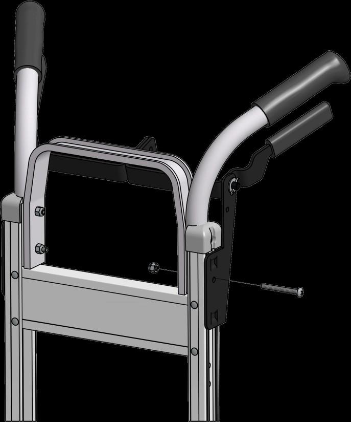
6 reated: 9/06/202, Revision: 2/20/204 able rake Handle omponents Loop Handles Loop Handle rake ssembly Pan Head Screw, /4-20 x 2-/ Lock Nut, / Handle Shown () #2 Phillips screwdriver () 7/6 wrench/socket. Remove existing handle fasteners from the 2 lower holes of handle/frame and discard. 2. Secure loop handle brake assembly () to frame/handle using /4-20 x 2-/4 screws () and nuts ( ) provided, aligning the mount plate in the frame channel and adjusting the height of the grip as needed. Double Grip Handles Double Grip Handle rake ssembly Pan Head Screw, /4-20 x 2-/ Lock Nut, / Handle Shown () #2 Phillips screwdriver () 7/6 wrench/socket. Remove existing handle fasteners from the 2 lower holes of handle/frame and discard. 2. Secure double grip handle brake assembly () to frame/ handle using /4-20 x 2-/4 screws () and nuts ( ) provided, aligning the mount plate in the frame channel and adjusting the height of the grip as needed Tread rake ssembly Instructions Page 5 of 0


 to frame with")


7 reated: 9/06/202, Revision: 2/20/204 able rake Handle omponents Vertical Grip Handles Vertical Grip Handle with rake Various* 7 Handle Shown () #2 Phillips Screwdriver () 7/6 wrench/socket * Handle part number and size will vary based on the option ordered.. Remove existing handle fasteners and handle, saving nuts and bolts. 2. ttach new vertical grip handle with brake () to frame with previously removed nuts and bolts. Single Grip Handles Single Grip Handle with rake Various* 3 Handle Shown () #2 Phillips Screwdriver () 7/6 wrench/socket * Handle part number and size will vary based on the option ordered.. Remove existing handle fasteners and handle, saving nuts and bolts. 2. ttach new single grip handle with brake () to frame with previously removed nuts and bolts Tread rake ssembly Instructions Page 6 of 0
 #2 Phillips")


8 reated: 9/06/202, Revision: 2/20/204 able rake Handle omponents Double Vertical Grip Handles Double Vertical Grip Handle rake ssembly Pan Head Screw, /4-20 x 2-/ Lock Nut, / () #2 Phillips Screwdriver () 7/6 wrench/socket. Remove existing handle fasteners from the handle/frame. Remove grey frame caps and discard, reattach nuts and bolts in the upper holes of the handle/frame. 2. Secure double vertical grip handle brake assembly () to frame/handle using /4-20 x 2-/4 screws () and nuts ( ) provided, aligning the mount plate in the frame channel and adjusting the height of the grip as needed. 57S Handle Tread rake ssembly Instructions Page 7 of 0


.")


 and yoke (G) on to the end of the cable")

9 reated: 9/06/202, Revision: 2/20/204 rake able omponents Item Description Qty. Part No. rake able Various* Hex Head Screw, /4-20 x otter Pin, Small D Nut, / E Jam Nut, / F levis Pin G Yoke G F E D. ttach brake cable () to the brake handle with bolt () and jam nut (E). ssembly will vary slightly based on the handle style. For vertical grip handles drop the cable through the hole in the handle before attaching to the lower assembly. () Needle nose pliers * rake cable part number and size will vary based on the option ordered. (2) 7/6 wrench/socket racket mounted brake handle Vertical grip style brake handle Single grip style brake handle 2. Thread nut (D) and yoke (G) on to the end of the cable assembly, threading until the yoke end aligns with the lower brake pull bar. 3. Secure the brake cable to the lower pull bar with clevis pin (F) and cotter pin (). djust the tension on the cable to ensure the brake shoes do not touch the wheels until the brake handle is engaged Tread rake ssembly Instructions Page 8 of 0


 Needle nose pliers (2) 7/6 wrench/socket.")
 thru the hole in the frame bracket (H)")
 is supplied, attach it to the frame with bolts (I) and")

10 reated: 9/06/202, Revision: 2/20/204 Tee Handle rake ssembly Tee Handle Various** Hex Head Screw, /4-20 x * otter Pin, Small D Nut, /4-20 or * F G -OR- E Jam Nut, / * F levis Pin G Yoke H D H Tee Handle racket * I Hex Head Screw, /4-20 x * D E I * Kit contents will vary based on the handle configuration ordered. ** Tee handle part number and length will vary based on the option ordered. () Needle nose pliers (2) 7/6 wrench/socket. To attach a tee handle to tread brakes on a Liberator hand truck, first pass the tee handle () thru the hole in the frame bracket (H) or the hole in the vertical grip from the top. If bracket (H) is supplied, attach it to the frame with bolts (I) and nuts (D) before passing the tee handle thru the bracket. 2. For hand trucks with lever style brake grips attach the top of the rod to the lever with bolt () and nut (E) Tread rake ssembly Instructions Page 9 of 0
 and yoke (G) on to the end of the tee handle (), threading")
 and cotter")


11 reated: 9/06/202, Revision: 2/20/204 Tee Handle rake ssembly 3. Thread nut (D) and yoke (G) on to the end of the tee handle (), threading until the yoke end aligns with the lower brake pull bar. 4. Secure the tee handle to the lower pull bar with clevis pin (F) and cotter pin (). djust the height of the tee handle to ensure the brake shoes do not touch the wheels until the brake handle is engaged. rake djustments fter extensive use adjustments may be needed to compensate for component and tread wear. able/ tee handle length adjustment. Loosen the mounting plate bolts and adjust the plate height until brake shoes are /6 from each wheel and retighten mounting bolts. 2. dditional adjustment can be made by shortening the length of the brake cable/tee handle by adjusting the height of the yoke/nut connecting the cable to the pull bar. Mounting plate adjustment Tread rake ssembly Instructions Page 0 of 0
Final Assembly Instructions Bikes with Threaded Headsets
 Final Assembly Instructions Bikes with Threaded Headsets Thank you for buying your new bicycle from L.L.Bean. Read these instructions carefully before beginning the final assembly. Prior to shipping, our
Final Assembly Instructions Bikes with Quill Stems
 Final Assembly Instructions Bikes with Quill Stems Thank you for buying your new bicycle from L.L.Bean. Read these instructions carefully before beginning the final assembly. Prior to shipping, our expert
Final Assembly Instructions Bikes with Threaded Headsets
 Final Assembly Instructions Bikes with Threaded Headsets Thank you for buying your new bicycle from L.L.Bean. Read these instructions carefully before beginning the final assembly. Prior to shipping, our
Import Bike Rack OEM INSTALLATION MANUAL
 Import ike Rack OEM INSTLLTION MNUL TLE OF ONTENTS System Information 2 Safety Information 2 Resources Required 3 Preparation 3 Under umper ttachment 3 Over umper ttachment 3 Installation 3 Under umper
HoldUp Plus2. Safety Kit included: See additional instructions for installation. REAR WHEEL TRAY. BASE (1x) lock WASHER (1x) KEY (2x) SAFETY CLIP (1x)
 lock WASHER (1x) KEY (2x) SAFETY CLIP (1x)") HoldUp Plus2 InsTAll This product on 2" hitch version of the HoldUp Front WHEEL TRAY assembly (1x) REAR WHEEL TRAY assembly (1x) wrench (1x) BASE (1x) bolt (8X) Lock WASHER (8X) Washer (8x) KEY (2x) SAFETY
HoldUp Plus2 InsTAll This product on 2" hitch version of the HoldUp Front WHEEL TRAY assembly (1x) REAR WHEEL TRAY assembly (1x) wrench (1x) BASE (1x) bolt (8X) Lock WASHER (8X) Washer (8x) KEY (2x) SAFETY
Beach Dolly with cradle & keel pad Assembly Instructions
 Beach Dolly with cradle & keel pad Assembly Instructions H G B A D C I J L F PART NAME QTY A. AXLE... 1 with tongue bracket and cradle supports attached B. CRADLE SUPPORT BAR... 2 C. TONGUE... 1 D. TONGUE
Final Assembly Instructions Bikes with 16 Wheel Size
 Final Assembly Instructions Bikes with 16 Wheel Size Thank you for buying your new bicycle from L.L.Bean. Read these instructions carefully before beginning the final assembly. Prior to shipping, our expert
Reproduction. Not for. Installation Instructions. Installation Instructions. Part No Installation. 32/36 Bagger 32/36 Kit WARNING
 Installation Instructions Installation Instructions 32/36 agger 32/36 Kit Part No. 5600268 its 32/36 Mowers Kit ontents Part No. Qty. escription Part No. Qty. escription 5404389 1 Weld, agger Mount, 32/36
INSTALLATION INSTRUCTIONS
 INSTALLATION INSTRUCTIONS Accessory (ROOF) P/N 08L07-E09-100 Application 6 PILOT Publications No. Issue Date JUN 5 PARTS LIST 6 Washers Bicycle attachment 2 Brackets Hex wrench 4 Knobs 2 Keys 1 Rear Bracket
VERSA BIKE RACK INSTRUCTIONS
 VERSA BIKE RACK INSTRUCTIONS Models #8, 8 Important This rack is designed for use with a or. receiver hitch. The rack is designed to hold a maximum of two bicycles. Do not use it for anything other than
VERTICAL SURFBOARD CARRIER READ ME! IMPORTANT WARNING!
 VERTICAL SURFBOARD CARRIER ENG RRAC09 30 min READ ME! Thank you for purchasing a Front Runner Vertical Surfboard Carrier. Before you start, take a moment to familiarize yourself with this Fitting Instruction
TRAILMATE METEOR ASSEMBLY MANUAL
 TRAILMATE METEOR ASSEMBLY MANUAL (DISC BRAKE VERSION) The Trailmate Meteor recumbent has been designed for easy assembly. This means more time to enjoy the smooth ride with single speed, 3 speed coaster
Santa Fe Cycles Assembly Guide Introduction
 Santa Fe Cycles Assembly Guide Introduction Congratulations on your purchase of your new Santa Fe bicycle. You have purchased a bicycle that has many features and qualities. Please take a few minutes and
INSTALLATION INSTRUCTIONS
 INSTALLATION INSTRUCTIONS Accessory (ROOF) P/N 08L07-E09-100 Application 2013 CROSSTOUR Publications No. AII 13168 Issue Date NOV 2012 PARTS LIST 6 Washers Bicycle attachment 2 Brackets Hex wrench 4 Thumbwheel
A A A
 Mossberg 0 GA Talon T Rear Pistol Grip with Scorpion Recoil System A.5.0.6 A.5.0.6 A.5.0.6 Extended Scorpion Material to Reduce and Discomfort to the Shooter's Hand and Thumb Sure-Grip Texture 70.0.0 Mossberg
Installation Instructions MODEL VSTI-A020 Tank Indicator Installation Model: VSTI-A020, Stainless Reverse Read System Versa Steel Inc. Guide Cables No
 Tank Indicator Installation Model: VSTI-A020, Stainless Reverse Read System Guide Cables No Guide Cables 1 August 4, 2011 Assembly Instructions: (Shown with a 2 board, 12 ft kit) ITEM NO. PART NUMBER DESCRIPTION
Important Note: Tighten lock nuts so the support tubes still swing freely see figure 2. There must be 1 2 threads of bolt past end of lock nuts.
 Kit Contents: DESCRIPTION QTY. DESCRIPTION QTY. 2 Shank Assembly 1 Support Tube Assembly 1 Side Tube - Short 2 1-1/4 Shank 1 Center Tube - Long 1 3/8-16 x 2.0 Carriage Bolt 2 5/16-18 x 2.25 Carriage Bolt
A A A
 Winchester SXP Talon T Rear Pistol Grip with Scorpion Recoil Grip A.5.0.65 A.5.0.65 A.5.0.65 Extended Scorpion Material to Reduce and Discomfort to the Shooter's Hand and Thumb Sure-Grip Texture Triton
Installation Guide RHT-380. This Manual Must Be Read Before Operating The Equipment CUSTOMER COPY
 Installation Guide This Manual Must Be Read Before Operating The Equipment RHT-380 Madison Heights, Michigan 48071 800-725-8377 www.snowexproducts.com CUSTOMER COPY Trynex International 2013 (REV B) F50767
CAUTION - PUT SAFETY FIRST
 www.shoremaster.com DVS Vertical Lift (Double V Side): Frame ssembly Instructions. Models: 500DVS - 0ft Wide, 5000lb Capacity - Part #: 0079 600DVS - 0ft Wide, 6000lb Capacity - Part #: 0033.. 3.. 5. CUTION
Installation Instructions
 116-3027, 116-3017 X-Pando Adjustable Steel Protector Installation Instructions 1404 N. Marshall Ave. El Cajon CA. 92020 For technical support call us at (800) 368-3075 NB 6/28/10 607-0112 Step 1. Mounting
Lectric Cycles Mid-Drive Electric Motor Installation
 Lectric Cycles Mid-Drive Electric Motor Installation This write-up describes the installation of a Lectric Cycles electric motor. The model is the e-rad Mid-Drive 750 Watt conversion kit, installed on
INSTALLATION INSTRUCTIONS
 INSTALLATION INSTRUCTIONS Accessory P/N 08L07-E09-100 Application 2013 ODYSSEY Publications No. AII 13265 Issue Date AUG 2012 Put this information in the glove box with the vehicle owner s manual. PARTS
DM-SL (English) Dealer's Manual. REVOSHIFT Shifter SL-RS47 SL-RS45 SL-RS36 SL-RS35 SL-RS34 SL-RS25
 Dealer's Manual. REVOSHIFT Shifter SL-RS47 SL-RS45 SL-RS36 SL-RS35 SL-RS34 SL-RS25") (English) DM-SL0002-03 Dealer's Manual REVOSHIFT Shifter SL-RS47 SL-RS45 SL-RS36 SL-RS35 SL-RS34 SL-RS25 IMPORTNT NOTICE This dealer's manual is intended primarily for use by professional bicycle mechanics.
(English) DM-SL0002-03 Dealer's Manual REVOSHIFT Shifter SL-RS47 SL-RS45 SL-RS36 SL-RS35 SL-RS34 SL-RS25 IMPORTNT NOTICE This dealer's manual is intended primarily for use by professional bicycle mechanics.
Detroit Speed, Inc. Rear Coilover Conversion Kit Camaro/Firebird P/N: &
 Detroit Speed, Inc. Rear Coilover Conversion Kit 1982-02 Camaro/Firebird P/N: 042440 & 042441 The Detroit Speed Inc., Rear Coilover Conversion Kit allows the latest in coilover spring/shock technology
Assembly Instructions for the Rolling Harrow and Board Turbo-Till 6/26/03
 Assembly Instructions for the Rolling Harrow and Board Turbo-Till 6/26/03 Your initial action is to locate the correct drag frame [(61) 589-107H through 589-116H]. Bolt the drag frame to the rear drag
HOME ASSEMBLY INSTRUCTIONS
 HOME ASSEMBLY INSTRUCTIONS This Papillionaire Bicycle now belongs to you. It will take you to work, wait patiently outside your local cafe, and carry your groceries home. This is the start of your long-term
Fontaine Fifth Wheel Ultra LT Rebuild Procedures
 Fontaine Fifth Wheel Ultra LT Rebuild Procedures Disassembly Assembly Adjustments 800-874-9780 2010 LT-147 January 2010 Dissassembly Cover plate removed for clarity. Refer to exploded view of assembly
E-trike Li Assembly Guide
 PREPARATION 1. Read this assembly manual BEFORE commencing assembly. 2. Carefully remove all the components and packaged hardware from the shipping boxes. 3. Unpack the contents of the large double box
TURF BROOM ATTACHMENT ASSEMBLY KIT
 TURF BROOM ATTACHMENT ASSEMBLY KIT INSTRUCTION BOOKLET Wood Bay Turf Technologies, 2012 1 Revised March 2012 PURPOSE OF THE KIT The purpose of this greensiron 3900, turf BROOM Kit is to enable owners of
Reproduction. Not for 27" & 29" TWO STAGE INTERMEDIATE SNOWTHROWERS Parts Manual for M1227E M1227EX M1529E
 Parts Manual for 27" & 29" TWO STAGE INTERMEDIATE SNOWTHROWERS 2011 Model No. Description 1696001 M1227E 1696002 M1227EX 1696003 M1529E Briggs & Stratton Yard Power Products Group 535 Macon Road McDonough,
Assembly Guide ST200 FUNCTIONAL TRAINER
 Assembly Guide ST200 FUNCTIONAL TRAINER Assembly Guide ST200 FUNCTIONAL TRAINER To avoid possible damage to this Functional Trainer, please follow these assembly steps in the correct order. Before proceeding,
SERIES 2 RAMP OWNER S MANUAL TOOLS REQUIRED: BEFORE YOU BEGIN... Read and understand these instructions before beginning a ramp setup.
 SERIES 2 RAMP OWNER S MANUAL BEFORE YOU BEGIN... Read and understand these instructions before beginning a ramp setup. Use caution and care for your back when lifting, pushing, pulling, folding or unfolding
Detroit Speed, Inc. A-body Rear Coilover Conversion Kit A-body (Moser Rear Axle) P/N: , , , , ,
 P/N: , , , , ,") Detroit Speed, Inc. A-body Rear Coilover Conversion Kit 1964-1972 A-body (Moser Rear Axle) P/N: 042411, 042412, 042413, 042417, 042418, 042419 The Detroit Speed, Inc. A-body Rear Coilover Conversion Kit
Detroit Speed, Inc. A-body Rear Coilover Conversion Kit 1964-1972 A-body (Moser Rear Axle) P/N: 042411, 042412, 042413, 042417, 042418, 042419 The Detroit Speed, Inc. A-body Rear Coilover Conversion Kit
Assembly Tools. Assembly will take about an hour
 Assembly Guide Assembly Tools Included in your parts box: Pedals Toolkit (4+5mm combo Allen wrench, 13+15mm combo open-end wrench) Touch-up paint Spare fuses (for battery) Assembly will take about an hour
Thank you for purchasing a WIKE BOX BIKE!
 Thank you for purchasing a WIKE BOX BIKE! Contents Safety.....3 Front wheel.4 Kickstand..5 Handle Bar & Box 6 Seat post and Saddle 7 Final pre-ride check 8 Tools needed to assemble Bike: -High table or
Caliber Sled Wheels Assembly Instructions for PN and 13579
 Caliber Sled Wheels Assembly Instructions for PN 13576 and 13579 Caution: Read all instructions before assembling or using Sled Wheels. Follow the steps in order. Only use Sled Wheels as intended, following
PRO1030 Bi-Directional Assembly Replacement
 PRO1030 Bi-Directional Assembly Replacement 1. Remove both side covers using the Crank and Cover Removal procedure. Fig. 1 2. Disconnect both brake cables (not shown) from the brake (S3611). (Fig. 1) 3.
BackCountry ebikes 2019 MULE Assembly
 BackCountry ebikes 2019 MULE Assembly Required Tools: Cutting Pliers (to cut box poly strapping and heavy bike banding) Scissors (to remove bubble wrap) Allen wrenches (3mm, 4mm, 5mm, 6mm) Wrenches (10mm,
Replaces Lesco 300 & 500 Parts
 Replaces Lesco 300 & 500 Parts ItemNo R&R PartNo PartNo Description Req. Qty Price R&R Reels Available, Lifetime Guaranteed 1 R502871 020800 R&R Reel, 9 Blade, Fits 300 1 32,100 1 R502871H R&R Only R&R
Fairlane & Meteor Instruction Package RC-114K. Rear Coilover Suspension Kit NOTE...
 ROD & CUSTOM Motorsports INCORPORATED 1962-1965 Fairlane & Meteor Instruction Package RC-114K Rear Coilover Suspension Kit NOTE... PLEASE READ ALL INSTRUCTIONS INCLUDED WITHIN THIS PACKAGE. IF AFTER READING
Installation Guide, MPower Echelon Console
 Installation Guide, MPower Echelon Console AC Performance, AC Sport and AC Performance Plus Schwinn Echelon Console (External Routing) 1. Install batteries to console. Mount the console to the bike. 2.
OPERATING and MAINTENANCE INSTRUCTIONS MAXIS 6K Puller (M6K-M)
") OPERATING and MAINTENANCE INSTRUCTIONS MAXIS 6K Puller (M6K-M) READ AND UNDERSTAND ALL OF THE INSTRUCTIONS AND SAFETY INFORMATION IN THIS MANUAL BEFORE OPERATING OR 04/17 (M6K-M) SERVICING THIS TOOL TABLE
OPERATING and MAINTENANCE INSTRUCTIONS MAXIS 6K Puller (M6K-M) READ AND UNDERSTAND ALL OF THE INSTRUCTIONS AND SAFETY INFORMATION IN THIS MANUAL BEFORE OPERATING OR 04/17 (M6K-M) SERVICING THIS TOOL TABLE
MODEL CHEST PULLEY SYSTEM
 MODEL 9180 CHEST PULLEY SYSTEM 1 PARTS LIST FOR CHEST PULLEY Note: Check with your architect or a professional contractor for hardware required to attach the unit to the wall and floor in your facility.
8MAY15 US RACK, Inc Falcon Drive, Madera, CA
 8MAY15 US RACK, Inc. - 2850 Falcon Drive, Madera, CA 93637-559-661-3050 INSTRUCTIONS for Bedrail-mounted MOTORCYCLE RACK, Model 2001-4TRA WARNING: Do NOT attempt to install or use this rack without following
Operator s/parts Manual
 Operator s/parts Manual 24 & 30 Folding No-Till Drill Harrow Manufacturing, Inc. P.O. Box 5060 Salina, Kansas 67402-5060! Read the Operator s manual entirely. When you see this symbol, the subsequent instructions
Parts List. 7. Handlebars 8. Grips 9. Handlebar Stem 10. Front Brake 11. Front Wheel 12. Crank 13. Chain
 Woodworm Cruise Parts List 1. Free Wheel with Rear Hub 2. Fenders 3. Fender Stay 4. Quick Release 5. Saddle 6. Seat Post 7. Handlebars 8. Grips 9. Handlebar Stem 10. Front Brake 11. Front Wheel 12. Crank
Universal Anchoring Adapter For Mercedes
 Universal Anchoring Adapter For Mercedes Anchoring Pin & Tube Set (For Most Mercedes Models) Users Manual 006 Chief Automotive Technologies, Inc. Chief s Limited One-Year Warranty & Liability CHIEF'S
TOYOTA TACOMA 2005 TOW HITCH Preparation. Part Number: PT
 Preparation Part Number: PT791 04050 Kit Contents 1 1 Hitch Center Section 2 1 LH Frame bracket 1 RH Frame Bracket 4 2 Auxiliary Bracket Hardware Bag Contents 1 6 Hex Head Bolt, M12 x 1.2 (black) 2 6 Nut,
TECHNICAL DATA ZTR Model 312
 DIXON INDUSTRIES. INC. A BLOUNT COMPANY AIRPORT INDUSTRIAL PARK PO BOX 1569 COFFEYVILLE KS 67337 0945 316 251 2000 FAX 316 251 4117 TECHNICAL DATA ZTR Model 312 IMPORTANT - READ OPERATOR'S MANUAL BEFORE
BICYCLE ASSEMBLY INSTRUCTIONS. dutchcycles.com.au. Distribution Centre
 BICYCLE ASSEMBLY INSTRUCTIONS dutchcycles.com.au Distribution Centre Shed 68, 400-422 Somerville Road, Tottenham, VIC 3012 email: service@dutchcycles.com.au BICYCLE COMPONENTS KEY INTRODUCTION CONGRATULATIONS
FLAT BAR ERGOPOWER 1 - TECHNICAL SPECIFICATIONS 2 - COMPATIBILITY WARNING! COMPATIBILITY
 ERGOPOWER FLT R 1 - TECHNICL SPECIFICTIONS 2 - COMPTIILITY WRNING! COMPTIILITY These controls were conceived, sized and created solely for use on roads. They are therefore not suited to other purposes
R152SVBBC. Spare parts Ersatzteile Pièces détachées Reserve onderdelen Repuestos Reservdelar I S E R V I C E
 S E R V I C E 5 I0500103 IPL, R152SVBBC, 2005-04, 544 08 36-01 95417024202 R152SVBBC Spare parts Ersatzteile Pièces détachées Reserve onderdelen Repuestos Reservdelar 544 08 36-01 2 NO. NO. DESCRIPTION
To save this document, scroll up and select the download icon
 Thank you for purchasing a RustySpokes Softcruise. We know you are going to enjoy the bike, but if you had it shipped to you, there are a few things you need to do to assemble the bike. The seat, pedals
Only. Gives You the TechLock. System Advantage ASSEMBLY, DISASSEMBLY AND TROUBLESHOOTING INSTRUCTIONS FOR 3000 SERIES FONTAINE
 April 00 Only Gives You the TechLock System Advantage ASSEMBLY, DISASSEMBLY AND TROUBLESHOOTING INSTRUCTIONS FOR 000 SERIES FONTAINE C o n n e c t y o u r b u s i n e s s w i t h F O N T A I N E April
Assembly Instructions for the Rolling Harrow and Reel Turbo-Till 6/26/03
 Assembly Instructions for the Rolling Harrow and Reel Turbo-Till 6/26/03 Your initial action is to locate the correct drag frame [(61) 589-107H through 589-116H]. Bolt the drag frame to the rear drag plates
Ladies Shopper Bike Assembly Manual 28C03
 Ladies Shopper Bike Assembly Manual 28C03 Ecosmo Ltd 1 Know your bike 1. Wheel 2. Rear Derailleur 3. Chain 4. Crank Set 5. Pedal 6. Seat Quick Lock 7. Saddle and Post 8. Frame 9. Front Light 10. Front
Symptom: The basic symptom is your sail will not roll in or out without force. The drum unit is hard to turn. Your sail will not roll out on its own.
 Schaefer 2100 roller furler drum replacement on Catalina 320 Danny Jensen, A BOA VIDA hull #972, Thanks to contributions Chris Burti, Jeff Hare and C320 group for comments Photos were taken and edited
Rear Drive System SERVICE INSTRUCTION. Specifications SI-R670B
 - SERVICE INSTRUCTION SI-R670B t Rear Drive System Before use, read these instructions carefully, and follow them for correct use. In order to realize the best performance, we recommend that the following
Marine 6-Boat Free-Standing Racks SKU: Updated November 2011
 Marine 6-Boat Free-Standing Racks SKU: 30-061 Updated November 011 Contains: Marine -Boat Free-Standing Racks (SKU 1-003) Marine 3 rd Boat Expansion Racks (SKU 1-0303) Marine Back Legs (SKU -001) 3 Sets
! CAUTION! ! WARNING! General Information
 Great Plains Mfg., Inc. Installation Instructions Used with: 2SF24, 24-Foot Two-Section Drill General Information Two-Section, Hydraulic Folding Marker 2SF30, 30-Foot Two-Section Drill 2SBM30, 30-Foot
ES-701 INSTRUCTIONS FOR USE
 BIKE ES-701 MANUAL ES-701 INSTRUCTIONS FOR USE 1) The model ES-701 is designed to be used as a group cycle in fitness studios and health clubs. It has a fixed wheel driven flywheel and should only be used
FDR CHRYSLER 16' CATAMARAN (MUSKETEER) The initial rigging of a sailboat is not difficult, but if the boat is strange
 The initial rigging of a sailboat is not difficult, but if the boat is strange") Page of 6 Revised 2/0/76 RIGGING INSTRUCTIONS FDR CHRYSLER 6' CATAMARAN (MUSKETEER) The initial rigging of a sailboat is not difficult, but if the boat is strange to the new owner, or the new owner is
Page of 6 Revised 2/0/76 RIGGING INSTRUCTIONS FDR CHRYSLER 6' CATAMARAN (MUSKETEER) The initial rigging of a sailboat is not difficult, but if the boat is strange to the new owner, or the new owner is
ASSEMBLY GUIDE AROUND THE BLOCK - 1, 3, 7, & 21 SPEED SIXTHREEZERO
 ASSEMBLY GUIDE AROUND THE BLOCK - 1, 3, 7, & 21 SPEED SIXTHREEZERO OUR COMMITMENT We want you to love your bike as much as we do. If you run into any issues, no matter how small, let us know and we ll
1650EXLT, ,
 1650EXLT, 96193008901, 2012-10 "CHASSIS, ENGINE & PULLEYS" - 000 00 00-00 W/O DESCRIPTION 1 B&S 21M307-0135-F1 FOR SERVICE & PARTS 1-800-233-3723 1 532 42 92-03 FRAME 1 2 532 15 04-06 BOLT 1 3 532 42 88-67
Row Marker OEM /
 IMPORTANT: Your new row marker is designed to attach to the Troy-Bilt Hiller-Furrower attachment. If you don t have Hiller- Furrower, call us or visit www.troybilt.com to place an order: OEM-290-250 for
MODEL / SINGLE and DUPLEX PULLEY SYSTEMS
 MODEL 922181/922182 SINGLE and DUPLEX PULLEY SYSTEMS MODEL 922181 SINGLE PULLEY SYSTEM MODEL 922182 DUPLEX PULLEY SYSTEM 1 PARTS LIST FOR SINGLE/DUPLEX COLUMN PULLEYS Note: Check with your architect or
Parts & Installation Instructions SV & SV 2 8.5, 9.5 & 10.5 and SVLD 7.5 Snow Plow
 Form -0 R September 0 Parts & Installation Instructions SV & SV.,. &. and SVLD. Snow Plow Item Part No. Part No. Part No. Part No. Part No. Part No. Qty. Description SVLD. SV. SV. SV. SV. SV. Moldboard
Assembly Tools. Assembly will take 1-2 hours
 Assembly Tools Included in your parts box: Pedals Quick release skewer Reflectors (if not already installed) Toolkit (4+5mm combo Allen wrench, 13+15mm combo open-end wrench) Helpful Tools: Scissors (for
Invacare Top End Parts Catalog
 Invacare Top End Parts Catalog T Titanium Top End Frames / Standard Parts Pre- July 2009 20 22 0 2 Pre- July 2009 9 2 2 Pre- July 2009 9 2 Titanium Head Tube Assembly see Casters / Forks on pg. 4 4 4 see
44in Side Discharge Mower for Wheel Horse XL 440H Lawn Tractors Model No Serial No and Up
 Form No. 5-8 in Side Discharge Mower for Wheel Horse XL 0H Lawn Tractors Model No. 790 Serial No. 5000000 and Up Operator s Manual Register your product at www.toro.com Original Instructions (EN) Contents
Cantilever Brake. Dealer's Manual. ROAD MTB Trekking. City Touring/ Comfort Bike
 (English) DM-RCBR001-00 Dealer's Manual ROAD MTB Trekking City Touring/ Comfort Bike URBAN SPORT E-BIKE Cantilever Brake BR-CX70 BR-CX50 BL-4700 BL-4600 BL-R780 BL-R3000 ST-7900 ST-6700 ST-5700 ST-4600
OPERATING and MAINTENANCE INSTRUCTIONS MAXIS 3K Puller (M3K-M)
") OPERATING and MAINTENANCE INSTRUCTIONS MAXIS 3K Puller (M3K-M) 04/17 (M3K-M) READ AND UNDERSTAND ALL OF THE INSTRUCTIONS AND SAFETY INFORMATION IN THIS MANUAL BEFORE OPERATING OR SERVICING THIS TOOL TABLE
OPERATING and MAINTENANCE INSTRUCTIONS MAXIS 3K Puller (M3K-M) 04/17 (M3K-M) READ AND UNDERSTAND ALL OF THE INSTRUCTIONS AND SAFETY INFORMATION IN THIS MANUAL BEFORE OPERATING OR SERVICING THIS TOOL TABLE
a division of Enviro Safety Products
 www.minutemanvac.com, a division of Enviro Safety Products.800.637.6606 Chassis 3 4 5 3 4 6 7 8 5 0 0 6 8 0 7 4 3 5 6 7 E 7e www.minutemanvac.com, a division of Enviro Safety Products.800.637.6606 Page
Installation/Care/Use Manual Soft Sides Fountains with FLEXI-GUARD
 Installation/Care/Use Manual Soft Sides Fountains with FLEXI-GUARD EDFP217C EDFP217RAC Installer To assure you install this model easily and correctly, PLEASE READ THESE SIMPLE INSTRUCTIONS BEFORE STARTING
Drive Belt Instructions
 Drive Belt Safety Do not roll, pry, twist, invert or bend the belt back on itself. Do not zip tie the belt. The acceptable temperature range for your belt drive is -53 C to 85 C. Do not lubricate the belt
1. General Safety Information. Silvio V2.2 Assembly Instructions Assembly. Adjust to the rider.
 Silvio V. Assembly Instructions support@cruzbike.com. General Safety Information WARNING to avoid serious injuries:. If you are unsure about fitting, testing and adjusting brakes or gearing on a bicycle,
TECHNICAL DATA BROCHURE Model 304
 DIXON INDUSTRIES, INC. A BLOUNT COMPANY AIRPORT INDUSTRIAL PARK PO BOX 1569 COFFEYVILLE KS 673370945 316 251 2000 FAX 316 251 4117 TECHNICAL DATA BROCHURE Model 304 IMPORTANT - READ OPERATOR'S MANUAL BEFORE
Thank you for purchasing a Porta-Dock product! *Please read and follow these instructions step by step*
 PG 1 OF 9 PORTA-DOCK, INC. 74A ABL/APW 1056 & 44A FLB APW 1056 PORTA-LIFT Thank you for purchasing a Porta-Dock product! *Please read and follow these instructions step by step* STEP 1. Separate and group
Mini Glider Manual. Your Glider comes partially assembled. The front wheel and the handlebars require assembly.
 Mini Glider Manual Congratulations on your purchase of the Mini Glider! Your glider is designed for years of nearly carefree use by your child. These instructions include how to set up your glider and
E-116 Assembly Guide
 E-116 Assembly Guide Table of Contents Overview of the assembly.... 2 1. Cable housing installation.... 3 2. Front brake installation.... 4 3. Rear brake installation... 5-6 4. Seatpost installation....
Parts Manual STRIKER Striker 2840 Parts List - PN Printed in USA 03/18/08
 Parts Manual STRIKER 2840 Striker 2840 Parts List - PN 238155 - Printed in USA 03/18/08 Standard Parts Recommended General Wear Parts Ref No Part Description Qty Part No 1 Squeegee Hose Assembly
EZee Glider Manual. Tools needed for Assembly: Wrench (included) Philips Screwdriver (not included) Assembly Instructions
 Philips Screwdriver (not included) Assembly Instructions") EZee Glider Manual Congratulations on your purchase of the EZee Glider! Your glider is designed for years of nearly carefree use by your child. These instructions include how to set up your glider and
EZee Glider Manual Congratulations on your purchase of the EZee Glider! Your glider is designed for years of nearly carefree use by your child. These instructions include how to set up your glider and
REPLACING THE FRONT RIM OF CROSSMAX SLR DISC, CROSSMAX SL DISC 07 AND CROSSMAX ST DISC WHEELS
 022 TECHNICALMANUAL07 WHEEL BUILDING REPLACING THE FRONT RIM OF CROSSMAX SLR DISC, CROSSMAX SL DISC 07 AND CROSSMAX ST DISC WHEELS 1 spoke wrench M40652 1 spoke wrench for aerodynamic spokes M40567 (for
830 SureFlo Soap Systems Installation Instructions. Foam Soap Cabinet... Pages 2-9 Liquid Soap Cabinet... Pages 10-19
 830 SureFlo Soap Systems Installation Instructions Foam Soap Cabinet... Pages 2-9 Liquid Soap Cabinet... Pages 10-19 INSTALLATION INSTRUCTIONS SureFlo SOAP DISPENSING SYSTEM FOAM VERSION ONLY B-830 Foam
CRUZBIKE Quest 2.0 Assembly
 CRUZBIKE Quest 2.0 Assembly CRUZBIKE Quest 2.0 Assembly... 1 General notes on assembly... 2 Un box and evaluate the frame and major parts... 2 Unfold the rear swing arm and arrange the frame... 3 Rear
STAND AID 1600/ ECONOSTAND
 MAKERS OF STAND AID, POWER TOILET AID AND FREEDOM CHAIR STAND AID 600/ ECONOSTAND INSTRUCTIONS AND WARRANTY FOR STAND AID 600 STAND AID SERIAL # PO BOX 386 Sheldon, IA 50 (800) 83-8580 (7) 34-53 Fax: (7)
Divider Systems. Rear Tire Divider (RTD) Section 4. Model Years Model Years Model Years
 Section 4. Model Years Model Years Model Years") Divider Systems Rear Tire Divider (RTD) Section 4 Model Years 1988 1993... 2-3 Model Years 1994 1996... 4-5 Model Years 1997 2010... 6-7 Model Years 2011 Present, Upper... 8-9 Model Years 2011 Present,
Divider Systems Rear Tire Divider (RTD) Section 4 Model Years 1988 1993... 2-3 Model Years 1994 1996... 4-5 Model Years 1997 2010... 6-7 Model Years 2011 Present, Upper... 8-9 Model Years 2011 Present,
Reproduction. Not for. Parts Manual. VCS404 16" Walk Behind Mower. Models
 Parts Manual Models Mfg. No. Description VCS404-BA Vantage 16" Walk Behind Mower VCS404-BB Vantage 16" Walk Behind Mower VCS404-BC Vantage 16" Walk Behind Mower VCS404 16" Walk Behind Mower Manual Part
Konza District Pinewood Derby Track Parts And Assembly Instructions
 Konza District Pinewood Derby Track Parts And Assembly Instructions - 1 - Pinewood Derby Track Parts List: Box 1 of 3 2 each - Race Track Flat Sections 1 each - Race Track Finish Line Section 1 each -
USER S MANUAL QUESTIONS? CAUTION. Model No. FMEX Serial No. Write the serial number in the space above for reference. Serial Number Decal
 Model No. FMEX81110.0 Serial No. Write the serial number in the space above for reference. USER S MANUAL Serial Number Decal QUESTIONS? If you have questions, or if parts are damaged or missing, please
Installation of 2 Tier In Line Greeting Card Rack
 Installation of 2 Tier In Line Greeting Card Rack Material Sent to Store: Greeting Card Fixtures: 4ft Inline Tier Kit (1 per every 4ft based on planogram) 3ft endcap Tier Kit (will not receive if planogram
MODEL TRIPEX PULLEY SYSTEM
 MODEL 922184 TRIPEX PULLEY SYSTEM 1 PARTS LIST FOR TRIPEX PULLEY SYSTEM Note: Check with your architect or a professional contractor for hardware required to attach the unit to the wall and floor in your
OWNER'S MANUAL LOCK-N-LOAD BULLET FEEDER (PISTOL)
") OWNER'S MANUAL LOCK-N-LOAD BULLET FEEDER (PISTOL) Table of Contents ASSEMBLY ASSEMBLY Pistol Bullet Feeder... Page 3 CHANGE-OVERS The Hornady Lock-N-Load Pistol Bullet Feeder is capable of feeding most
OWNER'S MANUAL LOCK-N-LOAD BULLET FEEDER (PISTOL) Table of Contents ASSEMBLY ASSEMBLY Pistol Bullet Feeder... Page 3 CHANGE-OVERS The Hornady Lock-N-Load Pistol Bullet Feeder is capable of feeding most
Vertical Lift: Frame Assembly Instructions. Model: ft Wide 7000lb Capacity - Part #:
 www.shoremaster.com 70068 Vertical Lift: Frame ssembly Instructions. Model: 70068-0ft Wide 7000lb apacity - Part #: 0070. 2. 3.. 5. UTION - PUT SFETY FIRST Before attempting to install or operate this
Shifting Lever. RAPIDFIRE Plus 11-speed
 (English) DM-SL0005-04 Shifting Lever Dealer's Manual RAPIDFIRE Plus 11-speed MTB XTR SL-M9000 DEORE XT SL-M8000 CONTENTS IMPORTANT NOTICE... 3 TO ENSURE SAFETY... 4 LIST OF TOOLS TO BE USED... 7 INSTALLATION...
Schaefer recognized this issue and they offer to replace the drum bearing assembly for $
 Schaefer 2100 roller furler drum replacement on Catalina 320 Danny Jensen, A BOA VIDA hull #972, Thanks to contributions Chris Burti, Jeff Hare and C320 group for comments Photos were taken and edited
LEAP ASSEMBLY MANUAL. Rev 1A
 LEAP ASSEMBLY MANUAL Rev 1A in the box BE MOVED Congratulations on purchasing an Xtracycle Leap DIY Cargo Bike Kit, and being one of the visionaries using the Leap to create your dream cargo- or passenger
Monsoon repair/service helper. To high: Shoot a couple of shots until you get under 210bar, if it is higher than 210bar it will
 Monsoon repair/service helper 1. Pressure: Min 180bar Max 210bar To low: Charge with air To high: Shoot a couple of shots until you get under 210bar, if it is higher than 210bar it will Not be able to
DM-RD (English) Dealer s Manual. ROAD Rear Derailleur RD-9000 RD-6800 RD-5800 RD-4700
 Dealer s Manual. ROAD Rear Derailleur RD-9000 RD-6800 RD-5800 RD-4700") (English) DM-RD0003-09 ROAD Rear Derailleur Dealer s Manual RD-9000 RD-6800 RD-5800 RD-4700 CONTENTS IMPORTANT NOTICE...3 TO ENSURE SAFETY...4 LIST OF TOOLS TO BE USED...6 INSTALLATION...8 Chain length...
(English) DM-RD0003-09 ROAD Rear Derailleur Dealer s Manual RD-9000 RD-6800 RD-5800 RD-4700 CONTENTS IMPORTANT NOTICE...3 TO ENSURE SAFETY...4 LIST OF TOOLS TO BE USED...6 INSTALLATION...8 Chain length...