Design and Integration of a Mechanical Aircraft Control System Mixer for Ruddervator Surfaces Advanced Tech Engineering, Inc.
|
|
|
- Duane Daniel
- 6 years ago
- Views:
Transcription

1 Design and Integration of a Mechanical Aircraft Control System Mixer for Ruddervator Surfaces Advanced Tech Engineering, Inc.


2 Requirements Design a control mechanism mixer that mechanically controls ailerons, and (v-tailed) ruddervators using a single handed yoke. Its movement should mimic the Microsoft Sidewinder Joystick. The mixer can be designed to connect to cables or pushrods, but I am not interested in the runs to the control surfaces, just the mixer. Size and cost are important design factors. I'd like for you to clearly depict the design solution using hand sketches and hand drawings. I would also like you to supply me with how many hours it took to complete the concept. 5.4 MS Sidewinder Joystick
3 Assumptions Aircraft: - Center-Stick Tandem Seating Aircraft Simplicity: - No use of gears and complex linkages - Keep the system low cost and low mass (i.e. size for stiffness, then strength) System: - All Control Surfaces have Control Horns with Moment Arms ~ 0.6" - Direct Mechanical Linkage and Mechanical Gain (increase or decrease through lever design) only through bell cranks and levers Calculations: - Use Small angle Approximations (for angles < 3 deg) in force-moment calculations - Maximum Control Surface Deflection are to be +30 deg for all Control Surfaces - Control Surface Deflection Rates to be at least 60 deg/sec - Control Surface Unit Weight = 3 lb/ft2 (may be high, but will use this for now) - Wingspan = 36 ft - Wing Chord = 6 ft - Aileron Length = 50% of b/2 = 9 ft (Outboard Half of Semi-span) - Aileron Chord = 20% of Wing Chord = 21.6 in
4 Assumptions (cont.) - Stall Speed = 50 KTAS at SLS where Q = 8.5 psf - Tail has Similar Aspect Ratio, but 1/3 Projected Horizontal Area with a 45 deg Dihedral Loads: - Zero Total Forces and Moments on Stick and Rudder Pedals in Neutral Position through the Flight Envelope - Balance the use of Tension Only Members (i.e. cables) vs. Push Rods to optimize tradeoff between Slop/Tolerance and Overall System Mass - Check Flight Envelope Highest Dynamic Pressure of 135 psf (200 KTAS at SL) vs. 6 g's Load Factor at Stall Speed Q and use the maximum Control Surface Moments of the two. - Maximum Stick Input Forces (5th Percentile Male at 1G Load Factor from Human Engineering Bulletin 56-5H) below the 100 KTAS Assumed Maneuver Speed - Aft Force = 42 lb (Pos X direction) - Fwd Force = 30 lb (Neg X direction) - Right Side Force = 15 lb (Pos Y direction) - Left Side Force = 8 lb (Neg Y direction) - Left Rudder Pedal Push Force = 334 lb (Neg X direction) - Right Rudder Pedal Push Force = 246 lb (Neg X direction)
.")
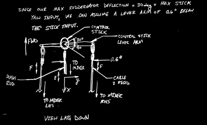
5 Answer Methods The method used in sizing Mixing Moment Arm Structure is explained below: The Maximum Travel of the Stick at + 30 degrees is fixed as equivalent to the corresponding Control Surface Maximum Deflections of + 30 degrees (see Assumptions). Also, the maximum Ruddervator Deflection Angle and the Maximum Rudder Pedal Deflection of + 20 degrees (see Assumptions and Illustration on left) correspond. The Rudder Pedal input is transferred aft to the Mixer to a point that is at the same waterline as the pivot axis. Thus, the Stick Pitch Deflection remains unaffected. Likewise, any Stick Pitch input that is transferred aft to the mixer does not transfer any rotation forward to the Rudder Pedals, leaving the two ruddervator affecters independent of each other.
6 Answer - Design Details The Mixer Assembly sits aft of the co-pilot in a tandem configuration aircraft. Push Rods run forward from the Ruddervators and aft from the Stick (Roll Input). Tension cables run from just outboard of the Rudder Pedals aft to where they address the Mixer as shown in the given illustration. The Roll Control function is not part of this mixing system and is intended to be the standard push rod and bell horn layout running outboard to the wing. Due to no requirement to understand loads, the maximum Control Surface Moments are not described in this project. However, this could be done using first-order analysis such as a flat plate with drag calculated as the Dynamic Pressure applied to the Exposed Control Surface centroid. Another calculation could be the maximum Load Factor condition pulling on the full control surface mass at the surface centroid coupled with the minimum drag vector (as stated earlier), to maximize the total Control Surface Moment. Depending on what the Maximum Load Factor is, the Maximum Moment can be understood. These maximum loads would be used to size the structural members that compose the Mixer Assembly, the Tension Cables running forward to the Rudder Pedals and it s respective fasteners, the Push Rods running from the Control Stick, and it s fasteners, to the Mixer and directly to the Ailerons through bell horns. (I can go into more depth on these calculations if you d like later). The development of Stick Force Feel can accomplished by understanding the desired stick forces (% of Max Load on a 5 th Percentile Human) for given Flight Envelope conditions and using levers such as bell cranks to dial the stick force up and down accordingly. A pitch trim mechanism can be created by applying a variable spring force (non-aero trim) on the Control Stick in the Pitch Axis.

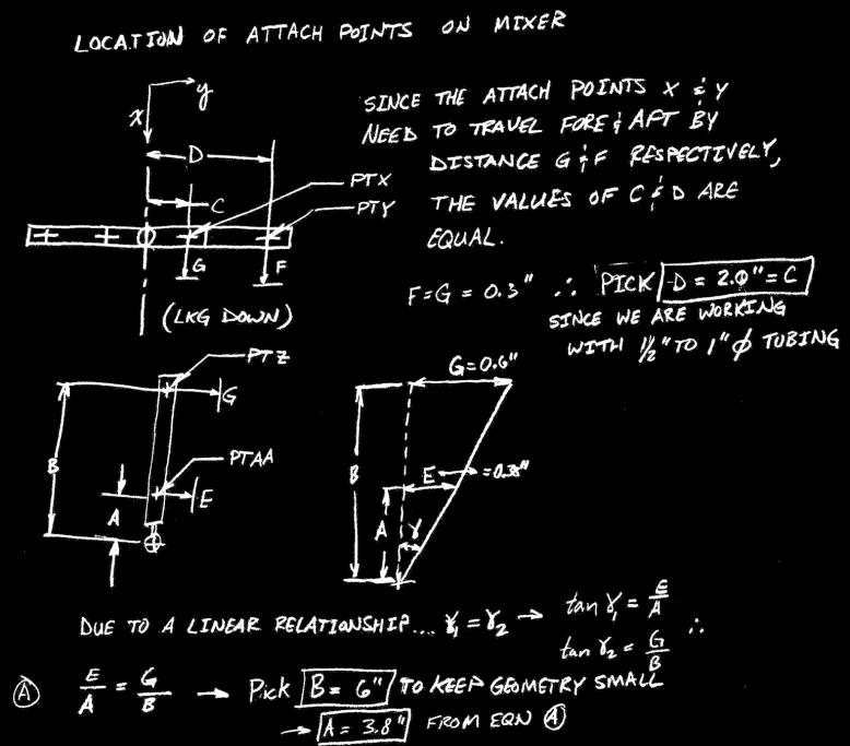
7 Answer Isometric View As drawn Dimensions are: A = 2.0 inches B = 6.0 inches C = 2.0 inches D = 3.8 inches
8 Answer - Parts List Below is a notional (incomplete) parts list for this system. MIXER QTY DASH NO. CAGE CODE PART NO. NOMENCLATURE MATERIAL NOTES PLATE, MOUNTING CRES 1.0" COUNTERBORE, 1/2" DIA 4 HOLE PATTERN MIXER STRUCTURE ALUMINUM 1" DIA ALUMUNUM TUBE X 6' LENGTH 2 070U6 AN42B-27 BOLT, EYE CRES 3/16" DIA, UNF, 2.5" GRIP LENGTH 4 AS 18-2-G SLEEVE, COMPRESSION 2 070U6 CABLE 3/32" DIA, 120.0" LENGTH 3 070U6 AN665-34R CLEVIS, MALE THREAD CRES 1/4" DIA HOLE 2 070U6 AN100-X THIMBLE, CABLE 3 070U6 INSERT CRES 3/8" ID, 1/2" OD, 1.0" LENGTH 1 070U6 JOINT, BALL 1.0" SPHERICAL HEAD 4 070U6 NUT, JAM CRES 3/16" DIA, UNF, 1/4" THICK 9 070U6 NUT, JAM CRES 3/8" DIA, UNF, 1/4" THICK 8 070U6 NUT, LOCKING CRES 1/8" DIA 6 AN PIN, COTTER CRES AN PIN, CLEVIS CAD PLATED 1/4" DIA, 1.5" LENGTH 3 070U6 ROD END CRES 3/8" DIA 3 070U6 ROD, PUSH CRES 3/8" DIA 8 070U6 SCREW CRES 1/8" DIA 4 070U6 AN960 WASHER, FLAT CRES 3/16" DIA, 0.031" THICK 9 070U6 AN960 WASHER, FLAT CRES 3/8" DIA, 0.031" THICK 4 070U6 WASHER, LOCKING CRES 3/16" DIA, 0.031" THICK 9 070U6 WASHER, LOCKING CRES 3/8" DIA, 0.031" THICK


9 Answer - Sketches As drawn Dimensions are: A = 3.8 inches B = 6.0 inches C = 2.0 inches D = 2.0 inches Half Travel: E = 0.38 inches F = 0.30 inches G = 0.30 inches * Note: These dimensions do not correspond to those noted on the previous slide. View Looking Down The two given illustrations characterize the Degrees of Freedom that are allowed by the Ball Joint at the bottom of the Mixer Assembly. View Looking Inboard Displacement of the Push Rods and Tension Cables can be calculated by the maximum deflection of either the Rotated Control Surfaces or the Rotated Control Stick, to whichever it is connected. Per the above illustration, Distances E, F & G have been found in the analysis given in the next slide.
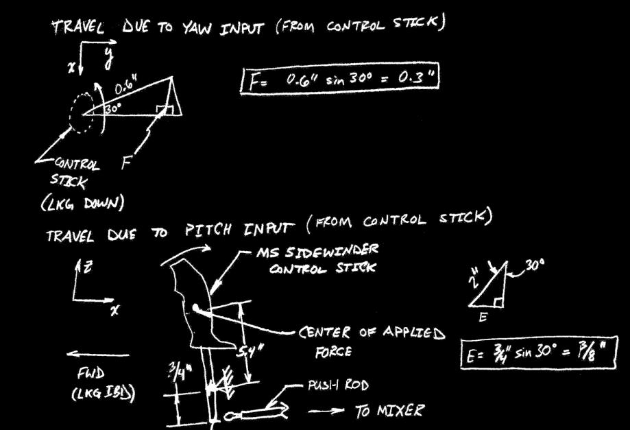
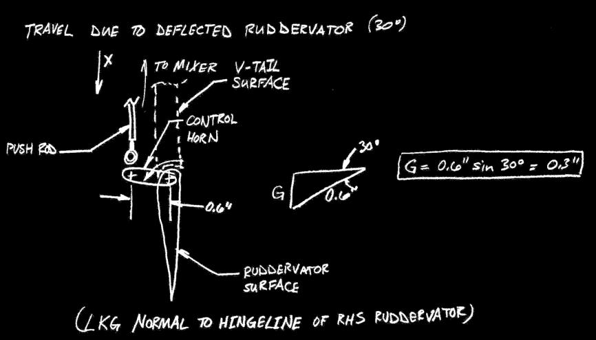
10 Answer - Calculations
11 Trade Study Answer - Trade Study Importance Merit Sub-Merit Type Target Rating Risk Score 100 Function Inputs per the MS Sidewinder Joystick Geometry 1 Optimize 5 No Risk Safety No Control System Binding 1 Optimize 3 Risk 54 Pilot Load Input to Operate in Worst Case 1 Optimize 3 Risk 80 Performance Low Mass 2 Minimize 3 No Risk 48 Natural Pilot Feel 2 Optimize 3 No Risk Operates in Adverse Scenarios 1 Optimize 3 Risk Supplies Adequate Control Power 1 Optimize 3 Risk 70 Value Long Life Cycle 2 Maximize 5 No Risk 70 Development Cost 2 Minimize 5 No Risk Production and Deployment Cost 2 Minimize 5 No Risk Sustainment and Disposal Cost 2 Minimize 5 No Risk 60 Integration Simple and Understandable 2 Optimize 5 No Risk 60 Low Part Count 2 Minimize 5 No Risk Non-Evasive Layout 2 Optimize 5 No Risk 50 "Ilities" Minimized Part Count 2 Minimize 5 No Risk 50 Multiple Function Components 2 Maximize 5 No Risk TOTAL Anything that is not a "5" with a Threshold Type is identified as a Risk. All Ratings Start as a "3" until they are proven to increase/decrease. For the Type Category, Threshold = 1, Range = System Capability Rating 84.9% Above is Qualitative to Quantitative Trade Study Analysis that personifies our Measures of Merit for the given Mixer System. Due to the weighted scoring, this very Trade Study can be pitted against alternative solutions for the Mixer Problem and produce a quantifiable and visual result. Also, the Trade Study alone delivers a Capability Rating that in essence measures our solution against an absolute answer by normalizing our results.
12 Level - Consequences Answer - Risk Mitigation Level - Likelyhood of Occurrence Low Risk = 1-3 Medium Risk = 4-6 High Risk = 7-10 Risk Control System Binding Adequate Pilot Load Input to Operate in Worst Case Supplies Adequate Control Power From the Trade Study Analysis in the previous slide, we can conclude that there are several Risks that will absolutely need to be addressed prior to engaging in production of any Airborne Prototypes. These Risks are demonstrated in this chart at their perceived Levels. We have a propensity to eliminate any and all risk in buildable hardware. However, as illustrated by the blue arrow, we can only translate our Total Risk Level left due to our inability to change our assumed Consequences, for this case.
, +30 pitch (stick), +20 deg yaw (pedals)) and it's relation to forces from Dynamic Pressure and Load Factor - Be careful to prevent binding")
13 Sensitivities - Design will be sensitive to Operating Load Factor (g's) - We want to design into the system a direct relation between Stick Forces and Dynamic Pressure (KEAS) for Safety (i.e. don't rip wings off at high Q, smoother flight, non-aerobatic maneuvers) - Maximize chord lengths on control surfaces to decrease sensitivity at higher dynamic pressure (for Safety). - Be aware of Stick Movement Envelope (+30 deg roll (stick), +30 pitch (stick), +20 deg yaw (pedals)) and it's relation to forces from Dynamic Pressure and Load Factor - Be careful to prevent binding of Control System in any way (i.e. sliding elements, if any, from "racking", stick and rudder pedal forces to not counter each other within the linkages and maintain straight hingelines (minimize curvature of bent hingeline) at high Load Factors.
14 Alternatives - I have an alternate, less robust concept of sliding sleeves and stops conceptually designed. - May consider use of only push rods to minimize slop if necessary. - May develop more ideas for changes in this layout to accommodate: - Side-by-side seating with a centerstick - Side-by-side seating with a sidestick - Tandem seating with a sidestick
Rigging the Pitts by Doug Sowder, IAC #14590
 Rigging the Pitts by Doug Sowder, IAC #14590 Pitts not flying so straight anymore? Don t believe that a Pitts can fly hands-off? Maybe you need to set aside a Saturday and do some rigging. The maintenance
II.E. Airplane Flight Controls
 References: FAA-H-8083-3; FAA-8083-3-25 Objectives Key Elements Elements Schedule Equipment IP s Actions SP s Actions Completion Standards The student should develop knowledge of the elements related to
Stability and Flight Controls
 Stability and Flight Controls Three Axes of Flight Longitudinal (green) Nose to tail Lateral (blue) Wing tip to Wing tip Vertical (red) Top to bottom Arm Moment Force Controls The Flight Controls Pitch
Flight Control Systems Introduction
 Flight Control Systems Introduction Dr Slide 1 Flight Control System A Flight Control System (FCS) consists of the flight control surfaces, the respective cockpit controls, connecting linkage, and necessary
Annex E(M) - Final inspection checklist - monowheel
 - Final inspection checklist - monowheel") Annex E(M) - Final inspection checklist - monowheel A/C Reg... Owner...Kit S/N...Date... (U.K. Only) L.A.A No...Inspector...Insp. No... Note: This check list only covers specific items for inspection of
Annex E(M) - Final inspection checklist - monowheel A/C Reg... Owner...Kit S/N...Date... (U.K. Only) L.A.A No...Inspector...Insp. No... Note: This check list only covers specific items for inspection of
AIRCRAFT PRIMARY CONTROLS A I R C R A F T G E N E R A L K N O W L E D G E
 1.02.02 AIRCRAFT PRIMARY CONTROLS 1. 0 2 A I R C R A F T G E N E R A L K N O W L E D G E CONTROLLING AIRCRAFT AIRCRAFT CONTROL SYSTEM In general, we use control inputs of the following devices in cabin:
VERSA BIKE RACK INSTRUCTIONS
 VERSA BIKE RACK INSTRUCTIONS Models #8, 8 Important This rack is designed for use with a or. receiver hitch. The rack is designed to hold a maximum of two bicycles. Do not use it for anything other than
CIRRUS AIRPLANE MAINTENANCE MANUAL MODELS SR22 AND SR22T CHAPTER 55-40: RUDDER GENERAL. Rudder 55-40: RUDDER. 1. General
 CIRRUS AIRPLANE MAINTENANCE MANUAL Rudder CHAPTER 55-40: RUDDER GENERAL 55-40: RUDDER 1. General The rudder provides airplane directional (yaw) control and includes a rudder trim tab used for yaw trim
PRIMARY FLIGHT CONTROLS. AILERONS Ailerons control roll about the longitudinal axis. The ailerons are attached to the outboard trailing edge of
 Aircraft flight control systems are classified as primary and secondary. The primary control systems consist of those that are required to safely control an airplane during flight. These include the ailerons,
CIRRUS AIRPLANE MAINTENANCE MANUAL
 RUDDER 1. GENERAL The rudder provides airplane directional (yaw) control and includes a rudder trim tab used for yaw trim adjustment. The rudder is of conventional design with skin, spar and ribs manufactured
My Background. Joe Wurts 1
 My Background Flying RC sailplanes since 1976 First competition 1977 US Nationals, placed 2 nd Only pilot to win world champion for both FAI recognized soaring disciplines FAI world record holder for declared
Bench Trimming A Stunt Ship
 Bench Trimming A Stunt Ship by Brett Buck "Bench Trimming" - this refers to setting up the initial trim of the airplane in the shop prior to flight. Since people have been flying stunt in its current form
Bugatti 100P Longitudinal Stick Forces Revision A
 Bugatti 1P Longitudinal Stick Forces Revision A Stick-free static longitudinal stability (stick force-per-knot) and stick-free longitudinal maneuvering stability (stick force-per-g) were computed for the
Aerodynamics Principles
 Aerodynamics Principles Stage 1 Ground Lesson 3 Chapter 3 / Pages 2-18 3:00 Hrs Harold E. Calderon AGI, CFI, CFII, and MEI Lesson Objectives Become familiar with the four forces of flight, aerodynamic
Principles of glider flight
 Principles of glider flight [ Lecture 2: Control and stability ] Richard Lancaster Email: Richard@RJPLancaster.net Twitter: @RJPLancaster ASK-21 illustrations Copyright 1983 Alexander Schleicher GmbH &
C-130 Reduction in Directional Stability at Low Dynamic Pressure and High Power Settings
 C-130 Reduction in Directional Stability at Low Dynamic Pressure and High Power Settings The C-130 experiences a marked reduction of directional stability at low dynamic pressures, high power settings,
Low Wind High Yields Series
 Low Wind High Yields Series Wind Turbines USER S MANUAL Introduction Low Wind High Yields Series rotor blades apply the latest advanced thermoplastic engineering and are manufactured by precision injection
TRAVSMART permanent single-cable horizontal lifeline system
 The Travsmart single-line system provides a smooth travel. It allows the traveler to move freely over the intermediate anchors, minimizing wear and eliminating user assistance. The user s hands remain
Preliminary Design Review (PDR) Aerodynamics #2 AAE-451 Aircraft Design
 Aerodynamics #2 AAE-451 Aircraft Design") Preliminary Design Review (PDR) Aerodynamics #2 AAE-451 Aircraft Design Aircraft Geometry (highlight any significant revisions since Aerodynamics PDR #1) Airfoil section for wing, vertical and horizontal
Preliminary Design Review (PDR) Aerodynamics #2 AAE-451 Aircraft Design Aircraft Geometry (highlight any significant revisions since Aerodynamics PDR #1) Airfoil section for wing, vertical and horizontal
Lesson: Pitch Trim. Materials / Equipment Publications o Flight Training Manual for Gliders (Holtz) Lesson 4.4 Using the Trim Control.
 Lesson 4.4 Using the Trim Control.") 11/18/2015 Pitch Trim Page 1 Lesson: Pitch Trim Objectives: o Knowledge o An understanding of the aerodynamics related to longitudinal (pitch) stability o Skill o Use of the pitch trim system to control
11/18/2015 Pitch Trim Page 1 Lesson: Pitch Trim Objectives: o Knowledge o An understanding of the aerodynamics related to longitudinal (pitch) stability o Skill o Use of the pitch trim system to control
V mca (and the conditions that affect it)
") V mca (and the conditions that affect it) V mca, the minimum airspeed at which an airborne multiengine airplane is controllable with an inoperative engine under a standard set of conditions, is arguably
V mca (and the conditions that affect it) V mca, the minimum airspeed at which an airborne multiengine airplane is controllable with an inoperative engine under a standard set of conditions, is arguably
SPM INDOOR TRAINING CYCLE ASSEMBLY MANUAL MODEL: SPM
 SPM INDOOR TRAINING CYCLE ASSEMBLY MANUAL MODEL: SPM Questions? As a quality exercise equipment supplier we are committed to your complete satisfaction. If you have questions, or find missing or damaged
R/C'ing the Revell 1/72 GATO Class Static Submarine Kit, Part-14. A Report to the Cabal:
 R/C'ing the Revell 1/72 GATO Class Static Submarine Kit, Part-14 A Report to the Cabal: I've invested over two weeks of continuous work to this project, and it's time to stick the WTC into the hull, install
BASIC AIRCRAFT STRUCTURES
 Slide 1 BASIC AIRCRAFT STRUCTURES The basic aircraft structure serves multiple purposes. Such as aircraft aerodynamics; which indicates how smooth the aircraft flies thru the air (The Skelton of the aircraft
CIRCLING THE HOLIGHAUS WAY -
 CIRCLING THE HOLIGHAUS WAY - OR DO YOU REALLY WANT TO KEEP THE YAW STRING CENTERED? BY RICHARD H. JOHNSON ANSWERS: 1. During Straight Flight - YES, that minimizes drag and maximizes the sailplane's performance.
THOR 10 HAMMER CAGE INSTRUCTIONS
 75 " 7m 78 4" m 6" 8.8m 45 ".70m 4.9deg 6 4" 6m 44 4".67m 75 " 7m 9 4" 0m 44".m 497 4".64m The 70, Thor Hammer Cage, consists of four heavy duty aluminum net poles. The unique pole structure reduces the
QuikVang. The Original High-Performance Vang INSTALLATION AND OPERATING INSTRUCTIONS MODEL D-30 MODEL D-40
 QuikVang The Original High-Performance Vang INSTALLATION AND OPERATING INSTRUCTIONS MODEL D-30 MODEL D-40 33 Broadcommon Road, Bristol, RI 02809 USA T: 401.253.4858 F: 401.253.2552 www.hallspars.com 1
Santa Fe Cycles Assembly Guide Introduction
 Santa Fe Cycles Assembly Guide Introduction Congratulations on your purchase of your new Santa Fe bicycle. You have purchased a bicycle that has many features and qualities. Please take a few minutes and
SKI SPECIFICATIONS INSTALLATION, MAINTENANCE, SERVICE INSTRUCTIONS & ILLUSTRATED PARTS LIST
 SKI SPECIFICATIONS INSTALLATION, MAINTENANCE, SERVICE INSTRUCTIONS & ILLUSTRATED PARTS LIST AIRGLAS MANUAL NO. L 44000-105 FOR SKI SERIAL NO. S 1 THRU 1000 AIRGLAS MODEL L 44000-11 FSN 1630-912-3166 SKI
SUBPART C - STRUCTURE
 SUBPART C - STRUCTURE GENERAL CS 23.301 Loads (a) Strength requirements are specified in terms of limit loads (the maximum loads to be expected in service) and ultimate loads (limit loads multiplied by
JAR-23 Normal, Utility, Aerobatic, and Commuter Category Aeroplanes \ Issued 11 March 1994 \ Section 1- Requirements \ Subpart C - Structure \ General
 JAR 23.301 Loads \ JAR 23.301 Loads (a) Strength requirements are specified in terms of limit loads (the maximum loads to be expected in service) and ultimate loads (limit loads multiplied by prescribed
SKI SPECIFICATIONS INSTALLATION, MAINTENANCE, SERVICE INSTRUCTIONS & ILLUSTRATED PARTS LIST
 SKI SPECIFICATIONS INSTALLATION, MAINTENANCE, SERVICE INSTRUCTIONS & ILLUSTRATED PARTS LIST AIRGLAS MANUAL NO. L 44000-105 (Rev C) FOR SKI SERIAL NO. S 1 THRU 1000 AIRGLAS MODEL L 44000-11 FSN 1630-912-3166
Aerodynamic Analysis of a Symmetric Aerofoil
 214 IJEDR Volume 2, Issue 4 ISSN: 2321-9939 Aerodynamic Analysis of a Symmetric Aerofoil Narayan U Rathod Department of Mechanical Engineering, BMS college of Engineering, Bangalore, India Abstract - The
MACH 6 TECH SCHEMATIC
 MACH 6 TECH SCHEMATIC 13 2 1 4 3 5 6 12 11 Item no. Qty 1 4 2 4 3 1 4 1 5 2 6 2 7 4 8 4 9 1 10 1 11 1 12 1 13 1 7 8 Description Mach Rocker V3 Upper Bolt Grey DW Link V2 Fwd Bearing Pivot rear der hanger
DIRECCION DE PERSONAL AERONAUTICO DPTO. DE INSTRUCCION PREGUNTAS Y OPCIONES POR TEMA
 MT DIREION DE PERSONL ERONUTIO DPTO. DE INSTRUION PREGUNTS Y OPIONES POR TEM 1 TEM: 0292 FLT/DSP - (HP. 03) ERODYNMIS OD_PREG: PREG20084823 (8324) PREGUNT: When are inboard ailerons normally used? Low-speed
Steps for W17, W14,W07, Wing Assembly Sonex #815
 CAUTION: This document is in no way a publication of Sonex Aircraft LLC. or any other corporation. All products mentioned are not necessarily recommended for use, but are included for informational purposes
DISCLAIMER: This scanned version of the Schweizer 2-33A Sailplane manual is provided without warranty of completeness or accuracy.
 DISCLAIMER: This scanned version of the Schweizer 2-33A Sailplane manual is provided without warranty of completeness or accuracy. It is solely as a service to builders of scale model aircraft who are
Objectives Topics Resources & Notes GAIN ATTENTION Review homework answers for chapter 8 Slide 1 OBJECTIVE
 9 Marine Steering Systems 83 COURSE LESSON TITLE PRESENTATION TIME PRESENTATION METHOD MATERIALS REQUIRED Chapter 9 Marine Steering Systems 2 hours Participative Lecture Ch9 PPT slides, computer, projector
i NOTE: This installation manual contains important information related to system
 TRx Pivot Plus Manual Elevating Legrests (ELR) Installation and Set-Up Manual i NOTE: This installation manual contains important information related to system set-up and adjustments. Please forward to
IMPORTANT: RECEIVING INSTRUCTIONS:
 Instruction Sheet Sidewinder Mechanical Bender IMPORTANT: RECEIVING INSTRUCTIONS: Visually inspect all components for shipping damage. If any shipping damage is found, notify carrier at once.shipping damage
CLASS I SERVICE INSTRUCTIONS
 CLASS I SERVICE INSTRUCTIONS 76 SUBJECT: EFFECTIVITY: REASON: No. 1057 ATA Code 27-20 FLIGHT CONTROLS - REPLACEMENT OF THE ELEVATOR AND RUDDER TAB PUSH RODS BEECHCRAFT Duchess 76, serials ME-1 through
METROLOGY LAB. I DEVICES BASED ON VERNIER SCALE
 METROLOGY LAB. I DEVICES BASED ON VERNIER SCALE Indirect Measurement; two balls 2 Lab6: Roundness Test 12/1/2017 Indirect Measurement; four balls 3 Lab6: Roundness Test 12/1/2017 Angle measurement using
Only. Gives You the TechLock. System Advantage ASSEMBLY, DISASSEMBLY AND TROUBLESHOOTING INSTRUCTIONS FOR 3000 SERIES FONTAINE
 April 00 Only Gives You the TechLock System Advantage ASSEMBLY, DISASSEMBLY AND TROUBLESHOOTING INSTRUCTIONS FOR 000 SERIES FONTAINE C o n n e c t y o u r b u s i n e s s w i t h F O N T A I N E April
CHAPTER 9 PROPELLERS
 CHAPTER 9 CHAPTER 9 PROPELLERS CONTENTS PAGE How Lift is Generated 02 Helix Angle 04 Blade Angle of Attack and Helix Angle Changes 06 Variable Blade Angle Mechanism 08 Blade Angles 10 Blade Twist 12 PROPELLERS
robart HOW-TO Series Model Incidence Meter
 robart HOW-TO Series Model Incidence Meter The term incidence is something of a misnomer since this highly versatile tool is capable of measuring or comparing angles other than incidence of a wing or tail.
Thank you for purchasing a WIKE BOX BIKE!
 Thank you for purchasing a WIKE BOX BIKE! Contents Safety.....3 Front wheel.4 Kickstand..5 Handle Bar & Box 6 Seat post and Saddle 7 Final pre-ride check 8 Tools needed to assemble Bike: -High table or
Brief Maintenance Manual DAR-Solo
 Brief Maintenance Manual DAR-Solo Sofia 2009 Page: 1 TABLE OF CONTENTS Introduction 3 Limitations and safety information 4 General view of DAR-Solo prototype 7 Technical Data 8 Inspection before and after
Nautique Triton Clamping Board Rack V2
 w w w.ro swe l l marine.co m Nautique Triton Clamping Board Rack V2 Installation & Usage Instructions Part # C917-180045 Information: info@roswellmarine.com If you have any questions please call : 1-21-68-11
Installation Instructions for the AlphaDeck Staging System
 Installation Instructions for the AlphaDeck Staging System Step 1 - Preparation A. Before setting up this system, determine the location of the stages and all the parts you will need. B. Read through the
Marine 6-Boat Free-Standing Racks SKU: Updated November 2011
 Marine 6-Boat Free-Standing Racks SKU: 30-061 Updated November 011 Contains: Marine -Boat Free-Standing Racks (SKU 1-003) Marine 3 rd Boat Expansion Racks (SKU 1-0303) Marine Back Legs (SKU -001) 3 Sets
Tread Brake Assembly Instructions
 reated: 9/06/202, Revision: 2/20/204 Tread rake ssembly Instructions Table of ontents: Lower rake omponents..2-4 able rake ssembly: rake Handle omponents..5-7 able ssembly....8 Tee Handle rake ssembly...9-0
MANDATORY BULLETIN No.: SAFETY RELATED. EV a SR. Appendix 1 Bulletin Flow Chart
 Appendix 1 Bulletin Flow Chart Form No.: QS-406/F-03A Issue: Date of Issue: Page: 2 APPENDIX 2 Inspection of Nicopress Pressing Tooling: Vernier calliper or Nicopress check gauge Felt-tip pen to mark clamps
FRONT DERAILLEUR - CURRENT RANGE
 FRONT DERAILLEUR - CURRENT RANGE (since 2015) (since 2018) (since 2017) (since 2018) WARNING! This technical manual is intended for use by professional mechanics. Anyone who is not a qualified professional
QUALITY ALUMINUM BOAT LIFTS, INC. INSTRUCTIONS. Dominator Lake Lift
 INSTRUCTIONS Dominator Lake Lift PHONE:251-986-3882 * FAX:251-986-3136 QABLDOMINATORINST.2014 P a g e 1 Quality Aluminum Boat Lifts, INC. Installation Instructions: Dominator Lake Lift Thank you for your
"Aircraft setup is a constant process really. Every
 The R/C Aircraft Proving Grounds - Aerobatics Setup Set Up for Success by: Douglas Cronkhite "Aircraft setup is a constant process really. Every time something is changed, there is the chance it will affect
Check the relevant hardware pertaining to your specific order.
 Check the relevant hardware pertaining to your specific order. ENGINE PACKAGE ( ) 1 Engine (with oil injection) Serial number: ( ) Rotax 447 SDCI ( ) Rotax 503 DCDI ( ) Rotax 582 DCDI ( ) 1 973 198 Rotax
A A A T E C H N O L O G Y
 A A A T E C H N O L O G Y & SPECIALTIES CO., INC. C O N S T A N T E F F O R T S U P P O R T S TOTAL SOLUTION SERVICE For the Industrial Piping Marketplace 2012 www.aaatech.com 4 1 Y E A R S S E R V I N
Aerodynamic Terms. Angle of attack is the angle between the relative wind and the wing chord line. [Figure 2-2] Leading edge. Upper camber.
![Aerodynamic Terms. Angle of attack is the angle between the relative wind and the wing chord line. [Figure 2-2] Leading edge. Upper camber.](/thumbs/82/86661300.jpg "Aerodynamic Terms. Angle of attack is the angle between the relative wind and the wing chord line. [Figure 2-2] Leading edge. Upper camber.") Chapters 2 and 3 of the Pilot s Handbook of Aeronautical Knowledge (FAA-H-8083-25) apply to powered parachutes and are a prerequisite to reading this book. This chapter will focus on the aerodynamic fundamentals
Chapters 2 and 3 of the Pilot s Handbook of Aeronautical Knowledge (FAA-H-8083-25) apply to powered parachutes and are a prerequisite to reading this book. This chapter will focus on the aerodynamic fundamentals
ZODIAC CH 601 XL. Tail Dragger (TD) or tail wheel configuration. TD configuration (shown with dual stick option and center console).
 or tail wheel configuration. TD configuration (shown with dual stick option and center console).") Tail Dragger (TD) or tail wheel configuration TD configuration (shown with dual stick option and center console). Ref 6B11-2 No cutout in the side skin 6B11-2 for the gear channel 6B5-5 When converting
Tail Dragger (TD) or tail wheel configuration TD configuration (shown with dual stick option and center console). Ref 6B11-2 No cutout in the side skin 6B11-2 for the gear channel 6B5-5 When converting
MUELLER. A Wall Type. Indicator Post. Reliable Connections. General Information 2. Technical Data/ Dimensions 3. Installation 4-5.
 Installation Instructions manual MUELLER table of contents PAGE A-20814 Wall Type General Information 2 Technical Data/ Dimensions Installation 4-5 Maintenance 6 Parts 7 Indicator Post! WARNING: 1. Read
Aerobatic Trimming Chart
 Aerobatic Trimming Chart From RCU - Chip Hyde addresses his view of Engine/Motor thrust. I run almost no right thrust in my planes and use the thottle to rudd mix at 2% left rudd. to throttle at idle.
COURSE OBJECTIVES CHAPTER 9
 COURSE OBJECTIVES CHAPTER 9 9. SHIP MANEUVERABILITY 1. Be qualitatively familiar with the 3 broad requirements for ship maneuverability: a. Controls fixed straightline stability b. Response c. Slow speed
Southern Eagles Soaring
 Southern Eagles Soaring N56LS Standard Cirrus Disassembly / Assembly Procedure. Version 2, 2017 You landed out so what now? First, hopefully you made arrangements with someone who has a hitch on their
BOEING COMMERCIAL AIRPLANE GROUP FLIGHT OPERATIONS TECHNICAL BULLETIN
 BOEING COMMERCIAL AIRPLANE GROUP FLIGHT OPERATIONS TECHNICAL BULLETIN NUMBER: 707 717 727 737 747 02-1 B-717-02-09 02-1 02-2 13 747-400 757 767 777 DC-8 50 68 68 10 DC-8-02-01 DC-9 DC-10 MD-80 MD-90 MD-10
NORMAL TAKEOFF AND CLIMB
 NORMAL TAKEOFF AND CLIMB CROSSWIND TAKEOFF AND CLIMB The normal takeoff is one in which the airplane is headed directly into the wind or the wind is very light, and the takeoff surface is firm with no
Pressure regulators Manually operated Fine setting valves. Brochure
 Pressure regulators Manually operated s Brochure Pressure regulators Manually operated s Qn = 9 l/min Actuating element: Push button Internal thread Poppet valve Qn = 9 l/min Actuating element: Push button
DM-RAPD (English) Dealer's Manual. ROAD MTB Trekking. City Touring/ Comfort Bike. SPD-SL Pedal DURA-ACE PD-R9100 ULTEGRA PD-R8000 SM-PD63
 Dealer's Manual. ROAD MTB Trekking. City Touring/ Comfort Bike. SPD-SL Pedal DURA-ACE PD-R9100 ULTEGRA PD-R8000 SM-PD63") (English) DM-RAPD001-01 Dealer's Manual ROAD MTB Trekking City Touring/ Comfort Bike URBAN SPORT E-BIKE SPD-SL Pedal DURA-ACE PD-R9100 ULTEGRA PD-R8000 SM-PD63 CONTENTS IMPORTANT NOTICE... 3 TO ENSURE
(English) DM-RAPD001-01 Dealer's Manual ROAD MTB Trekking City Touring/ Comfort Bike URBAN SPORT E-BIKE SPD-SL Pedal DURA-ACE PD-R9100 ULTEGRA PD-R8000 SM-PD63 CONTENTS IMPORTANT NOTICE... 3 TO ENSURE
HoldUp Plus2. Safety Kit included: See additional instructions for installation. REAR WHEEL TRAY. BASE (1x) lock WASHER (1x) KEY (2x) SAFETY CLIP (1x)
 lock WASHER (1x) KEY (2x) SAFETY CLIP (1x)") HoldUp Plus2 InsTAll This product on 2" hitch version of the HoldUp Front WHEEL TRAY assembly (1x) REAR WHEEL TRAY assembly (1x) wrench (1x) BASE (1x) bolt (8X) Lock WASHER (8X) Washer (8x) KEY (2x) SAFETY
HoldUp Plus2 InsTAll This product on 2" hitch version of the HoldUp Front WHEEL TRAY assembly (1x) REAR WHEEL TRAY assembly (1x) wrench (1x) BASE (1x) bolt (8X) Lock WASHER (8X) Washer (8x) KEY (2x) SAFETY
DECREE TECH FEATURES FELT LONG, LOW, SLACK GEOMETRY
 TECH FEATURES FELT DECREE In October 2015, Felt Bicycles introduced an entirely new trail bike into its family: the Decree. Through many iterations of development and design, plus demanding testing and
X-29 Canard Jet. A Simple Depron Foam Build.
 X-29 Canard Jet. A Simple Depron Foam Build. Two full sized X-29 s were built and the first flew in 1984. They were experimental aircraft, testing this unusual configuration of a canard jet with swept
Flight Controls. Chapter 5. Introduction
 Chapter 5 Flight Controls Introduction This chapter focuses on the flight control systems a pilot uses to control the forces of flight, and the aircraft s direction and attitude. It should be noted that
Lectric Cycles Mid-Drive Electric Motor Installation
 Lectric Cycles Mid-Drive Electric Motor Installation This write-up describes the installation of a Lectric Cycles electric motor. The model is the e-rad Mid-Drive 750 Watt conversion kit, installed on
QuikVang. The Original High-Performance Vang INSTALLATION AND OPERATING INSTRUCTIONS MODEL A-8 MODEL A-12
 QuikVang The Original High-Performance Vang INSTALLATION AND OPERATING INSTRUCTIONS MODEL A-8 MODEL A-12 33 Broadcommon Road, Bristol, RI 02809 USA T: 401.253.4858 F: 401.253.2552 www.hallspars.com 1 INTRODUCTION
Winnipeg Headingley Aero Modellers. Things About Airplanes.
 Winnipeg Headingley Aero Modellers Things About Airplanes. Table of Contents Introduction...2 The Airplane...2 How the Airplane is Controlled...3 How the Airplane Flies...6 Lift...6 Weight...8 Thrust...9
Aircraft - Very Heavy Lift at Very Low Cost
 Aircraft - Very Heavy Lift at Very Low Cost Stephen Funck This is a span loader for standard shipping containers. The design goal is the lowest cost per ton / mile. Low wing loading allows for low flight
INSTRUCTIONS 360 Y-DROP HAGIE STS 2015
 INSTRUCTIONS 60 Y-DROP HAGIE STS 05 INSTRUCTIONS 60 Y-DROP HAGIE STS 05 INTRODUCTION Before beginning, it s important to know where each mounting bracket fits relative to the row spacing involved. The
TAKEOFF & LANDING IN ICING CONDITIONS
 Original idea from Captain A. Wagner T TAKEOFF & LANDING IN ICING CONDITIONS here have been a number of accidents related to take-off in conditions in which snow and/or other forms of freezing precipitation
Planning and general precautions ithrust Tunnel Systems installations.
 Version 1.0 This recommendation will go through the different factors to consider when choosing where and how to fit thruster tunnels in a boat. Some of these recommendations might be difficult, or even
STOL CH rd Edition Drawings, dated April 16, 2012 Summary of changes from Edition 2 Revision 1 to Edition 3.
 STOL CH 750 3 rd Edition Drawings, dated April 16, 2012 Summary of changes from Edition 2 Revision 1 to Edition 3. Page Date Drawing Title 75-G-0 04/12 Three View Drawing 1. Edition 3 75-G-1 04/12 Drawings
SCOUT DECK ANCHOR 3 1/4" BONDING SCREW
 SCOUT DECK ANCHOR 16" 16" 1" X 4" ANCHOR BOLT (4) 10" 3 1/8" 5" 6" MIN COPPER WIRE TO ATTACH TO BONDING GRID 3 1/4" BONDING SCREW CONCRETE DECK SPECIFICATIONS: THE AQUA CREEK PRODUCTS' SCOUT DECK ANCHOR
A103 AERODYNAMIC PRINCIPLES
 A103 AERODYNAMIC PRINCIPLES References: FAA-H-8083-25A, Pilot s Handbook of Aeronautical Knowledge, Chapter 3 (pgs 4-10) and Chapter 4 (pgs 1-39) OBJECTIVE: Students will understand the fundamental aerodynamic
MASTER TRUING STAND TS-3. Optional Dial indicator set with brackets Dial indicator bracket set only
 MASTER TRUING STAND TS-3 3 2 1 3 8 9 4 10 7 6 5 12 13 Optional 1555-1 Dial indicator set with brackets 1556-1 Dial indicator bracket set only 49 11 16 14 15 48 32 31 37 38 20 19 17 18 34 39 21 36 22 33
DIRECCION DE PERSONAL AERONAUTICO DPTO. DE INSTRUCCION PREGUNTAS Y OPCIONES POR TEMA
 MT DIREION DE PERSONL ERONUTIO DPTO. DE INSTRUION PREGUNTS Y OPIONES POR TEM 1 TEM: 0114 TP - (HP. 03) ERODYNMIS OD_PREG: PREG20078023 (8358) PREGUNT: What is the safest and most efficient takeoff and
Ladies Shopper Bike Assembly Manual 28C03
 Ladies Shopper Bike Assembly Manual 28C03 Ecosmo Ltd 1 Know your bike 1. Wheel 2. Rear Derailleur 3. Chain 4. Crank Set 5. Pedal 6. Seat Quick Lock 7. Saddle and Post 8. Frame 9. Front Light 10. Front
SPOOLER INSTRUCTIONS. STEP 12 If you are going to paint your posts, that should be done at this time.
 STEP 4 Starting where you marked the end post location, move down your fence line 6 feet and make another mark. This mark is where your second upright post will be installed. Continuing down the fence
Wellhead Mast. Installation and Operation Guide. Nanometrics Inc. Kanata, Ontario Canada
 Installation and Operation Guide Nanometrics Inc. Kanata, Ontario Canada 2001 2005 Nanometrics Inc. All Rights Reserved. Installation and Operation Guide The information in this document has been carefully
5. STRUCTURAL ANALYSIS
 5. STRUCTURAL ANALYSIS The skeletal structure of the experiment casing is constructed from UNISTRUT with all experiment equipment mounted by UNISTRUT provided fasteners. All maximum loads for nuts, bolts,
8MAY15 US RACK, Inc Falcon Drive, Madera, CA
 8MAY15 US RACK, Inc. - 2850 Falcon Drive, Madera, CA 93637-559-661-3050 INSTRUCTIONS for Bedrail-mounted MOTORCYCLE RACK, Model 2001-4TRA WARNING: Do NOT attempt to install or use this rack without following
Homework Exercise to prepare for Class #2.
 Homework Exercise to prepare for Class #2. Answer these on notebook paper then correct or improve your answers (using another color) by referring to the answer sheet. 1. Identify the major components depicted
TECHNICAL INFORMATION
 TECHNICAL INFORMATION Model No. Description RP2300FC, RP2301FC Router CONCEPT AND MAIN APPLICATIONS Models RP2300FC and RP2301FC are upgraded sister tools of our current plunge-type electronic router Model
Apex 3 Theory of Operation
 Apex 3 INSTALLATION & OVERVIEW... 2 Load Height... 2 Approach Angle... 2 Footprint... 3 Protrusion... 3 Mounting the Apex3... 4 General Torque Specs... 5 OPERATION OF BIKE RACK... 6 Loading Bikes... 6
Aegea Assembly Notes:
 Aegea Assembly Notes: The Aegea model is a thermal Duration (TD) model made up of components from Phil Barnes 1 (bagged wing and tail group) and Terry Luckenback 2 (Pretty Mantis fuse). Due to its construction
REPLACING THE AFT RUDDER CABLES
 REPLACING THE AFT RUDDER CABLES Note: You must have the assistance of a qualified Aircraft Mechanic to perform this procedure. A logbook entry with the mechanics signature is required. Please read these
Analysis of the Z-wing configuration
 School of Innovation, Design and Engineering BACHELOR THESIS IN AERONAUTICAL ENGINEERING 15 CREDITS, BASIC LEVEL 300 Analysis of the Z-wing configuration Author: Joakim Avén Report code: MDH.IDT.FLYG.0231.2011.GN300.15HP.Ae
Stalls and Spins. Tom Johnson CFIG
 Stalls and Spins Tom Johnson CFIG Contents Angle of Attack Stall Recognition and Recovery Spin Entry and Recovery Load Limit Considerations Gust Induced Stall and Spin Accidents Stalls a stall is a loss
Magnetic Bike. Model No: AENERGISER BODY WORX. Retain this owner s manual for future reference Read and follow all instructions in this owner s manual
 BODY WORX Magnetic Bike Model No: AENERGISER Retain this owner s manual for future reference Read and follow all instructions in this owner s manual Version A 1 EXPLODE DRAWING -02- PARTS LIST AND TOOLS
file://c:\program Files\Microsoft Games\Microsoft Flight Simulator X\FSWeb\lessons\Stud...
 Page 1 of 7 Lesson 2: Turns How Airplanes Turn Fly This Lesson Now by Rod Machado There are many misconceptions in aviation. For instance, there are pilots who think propwash is a highly specialized detergent.
OP CHECKLIST FOR 1D CONSOLIDATION LABORATORY TEST
 Page 1 of 5 WORK INSTRUCTIONS FOR ENGINEERS NHB Compiled by : LSS Checked by : GSS Approved by : OP-3-31. CHECKLIST FOR 1D CONSOLIDATION LABORATORY TEST Page 2 of 5 31.0 CHECKLIST ITEMS *(refer to respective
NEXT GENERATION FLEX FENCE
 NEXT GENERATION FLEX FENCE Area To Be Fenced.. With Next Generation Flex Fence any post that is not in a straight line with another post must be braced. Layout your fence installation. Determine all end
Millennial Walker A multi-functional, elderly assistance walker with improved posture, comfort, and folding capabilities.
 Millennial Walker A multi-functional, elderly assistance walker with improved posture, comfort, and folding capabilities. Background & Research Question There are many different styles and categories when