RACE BOX. Installation and Operation Manual English
|
|
|
- Arthur Todd
- 6 years ago
- Views:
Transcription
1 RACE BOX Installation and Operation Manual
2 RaceBox 1
3 RaceBox Edition: Mar 2012 This manual is written for Nexus RaceBox
4 RaceBox 1 Part specification Overview Calculated Data Installation Mounting Serial / FDX Cable Pushbutton Buzzer Software Configuration Polar File Configuration File Startup Shutdown Race Box Features and Their Use Data Logging NXB Log CSV Log Target & Polar Boat Speed Polar File Choosing Whether TBS or PBS is Sent to the Nexus Network Displaying TBS and PBS in Other Fields Set Steer Memory Man Overboard (MOB) Start Line Tactical Assistance In Sequence Data vs Out Of Sequence Data Configuring which data is sent to which fields Using the Race Box timer Starting the timer Syncing the timer Interpreting the data. What does it all mean? How does the Race Box choose its target? How does the Race Box choose the path to the target? Distance and time to line calculations Perpendicular Mode Starting examples Reach in, reach out start The Vanderbilt start Other starting strategies Connecting a GPS Receiver Other Configuration Options Bow Location and Boat Length Position Data Source Status Lights Data Damping Error Conditions AVAILABLE DATA FIELDS BIAS Starting line bias PBS - Polar Boat Speed TBS - Target Boat Speed TTL - Time to start line in seconds TTB - Time to Burn
5 RaceBox MTL - Meters to start line FTL - Feet to start line BL - Boat Lengths to start line OPT_A - The optimum apparent wind angle OPT_T The optimum true wind angle Specifications Technical specifications Compss Instrument Warranty
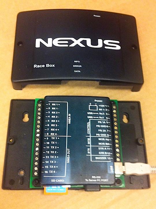
6 RaceBox 1 Part specification Items delivered with the Race Box Qty Description 1 The Race Box 1 push button 1 buzzer 1 DB9 male to DB9 female serial cable 1 power cable 1 SD memory card 4 Mounting screws 1 This manual Registering this product Once you have checked that you have all the listed parts, please take time to fill in the warranty document and return it to your national distributor. By returning the warranty card, it will assist your distributor to give you prompt and expert attention. Keep your proof of purchase. Your details will also be added to our customer database so that you automatically receive new product catalogues when they are released. Warranty conditions see 8. 5
7 RaceBox 2 Overview Thank you for purchasing the Nexus Race Box! The Nexus Race Box is a great addition to any Nexus instrument system with an FDX server. Our Race Box can calculate both polar and target boat speed (PBS & TBS), log your instrument data in both Nexus native binary NXB format and comma separated values (CSV) format and assist your tactician in making the best start possible. From time to time, firmware upgrades will be released for the Race Box, and these can easily be installed. Instructions for upgrading the firmware will be provided with each update. Information generated by the Race Box is sent to Nexus instruments in accordance with the Race Box configuration. This will be discussed in detail later in this manual, but in general, you can send Race Box data to any NX2 or NXR instruments. This includes the NX2 Multi, the Multi XL, the NXR Multi and the larger NXR instruments. The Race Box is powered by 12 volts DC, just as the Nexus server is. A standard, DB9 male to DB9 female straight through serial cable connects the Race Box to the Server data port. To get the most out of your Race Box, you'll want to have a Nexus buzzer installed on your FDX server and a Nexus push button connected to the Race Box. The Race Box will provide the SET STEER and MOB functions you're used to, so you won't need an additional button. In fact, with the Race Box, all these functions and more are controlled with a single button. You can reuse the button that is currently connected to your server if you have one. The Race Box requires that a standard SD memory card be installed. This card will have your polar table and your configuration file, both of which are read when the Race Box starts up. Your log files will also be stored on this card. After your racing, you can easily remove the card and use any computer with an SD card reader to review your data. The Race Box has four, full duplex RS-422 connections for communication with NMEA 0183 and other devices. Future firmware updates will allow the connection of some peripherals to these connectors. In the initial release, you can connect a NMEA 0183 GPS receiver to the Race Box. The Race Box will accept the RMC sentence up to 5 times per second, for high speed position, COG and COG updates. The Race Box also has three colored lights which can be seen through the translucent case. These lights, referred to as the status lights or status LEDs, will be explained in detail later in this manual. Finally, the Race Box has connections for MOB, SET STEER and a buzzer. These are for future use and currently are left unconnected. How does it do all that? 6
8 RaceBox Fundamentally, all the Race Box does is accept data from the Nexus server, do some processing on it and then sends the results to the Nexus server to be published on the Nexus network. For the most part, this data is just displayed to the crew. In Classic and NX2 series instruments, three special data fields exist which can hold calculated data. These are TBS, CAD and CFD. TBS is a special field, and it is used only for speed targets (more on this later). The NXR series supports these and ten additional fields, referred to as CUSTOM0 through CUSTOM9. With the Race Box, the crew can configure what information gets sent to each of these fields, within certain limitations. For example, if the Race Box is calculating time to line (TTL), we have to tell it which field to display this information in. If we have only NX2 instruments, then the choices are CAD and CFD. With the NXR, we have ten additional choices. So the primary method of giving the crew data while sailing is simply displaying the data on the instruments. There are logs kept which can be viewed after you're done sailing. The status lights also offer some information. Once connected, data is received into the Race Box from the Nexus server. This is done automatically. Also, there is a button that is used to control the Race Box and also the Nexus server. This is used to tell the Race Box where the starting line begins and ends, as well as to control some other features. Like any computer, the not-so-old saying applies: Garbage in, garbage out. To get the best information from the Race Box requires that your Nexus system be well calibrated and that the crew understand how it works and what the numbers it is presenting mean. This manual will explain all that for you and, if you have questions, you can contact Nexus support. 2.1 Calculated Data For a list of data fields that the Race Box can calculate, please refer to Appendix 'A'. 7
9 RaceBox 3 Installation The installation includes 5 major steps: 1. Read the installation and operation manual. 2. Plan where to install the RaceBox. 3. Run the cables. 4. Install the RaceBox. 5. Learn the functions and setting up your system. Before you begin drilling... think about how you can make the installation as neat and simple as your boat will allow. Plan where to position the transducer and instrument. Think about leaving space for additional instruments in the future. A few do nots you should consider: Do not cut the cables too short. Allow extra cable length at the RaceBox so it can be disconnected for inspection without having to disconnect all attached cables. Do not run cables in the bilge, where water can appear. Do not run cables close to fluorescent light sources, engine or radio transmitting equipment to avoid electrical disturbances. Do not rush, take your time. A neat installation is easy to accomplish. The following material is needed: Wire cutters and strippers. Small and large Philips and a small flat head screw driver. Hole saw to cut a hole for the instrument back of 63 mm (2½"). 2.8mm drill for the RaceBox mounting screws Plastic cable ties If you are doubtful about the installation, obtain the services of an experienced technician. Installation 3.1 Mounting First, find a suitable mounting location for the Race Box. Any location suitable for the Nexus Server should serve equally well for the Race Box. You will notice that, just like the Nexus server, the Race Box only has openings on one side. Also like the server, the Race Box should be mounted so that it's bottom is against a vertical surface and the side with the wire openings is oriented downward. This is so that any water which may inadvertently splash on to the box is more likely to run off the box instead of into it. The Race Box need not be mounted in close proximity to the server if this is your preference, as long as you can connect a serial cable between the Race Box and the Server. Once you have located a suitable mounting location, use the four supplied mounting 8
10 RaceBox screws to mount the Race Box. You will beed to remove the outer lid to expose the mounting holes. Once the Race Box is mounted, leave the outer lid removed until the installation procedure is complete. 12VDC Power Next, hook up power leads to the Race Box. The Race Box is powered by 12 Volts DC and requires as much as approximately 0.17 amperes of current under certain conditions (but typically uses much less). Please see the diagram in figure yyy to locate the 12VDC connection terminal. You may connect the Race Box to the same power switch/breaker as your Nexus server if you like. However, if you think you will want to change your polar table during a day of racing without having to reset the rest of your Nexus instrument system, then you will want to provide the Race Box with a dedicated switch. 3.2 Serial / FDX Cable The next step is to connect the supplied serial cable between the Nexus Server and the Race Box. Be sure to tighten the thumb screws on the cable so that neither end falls out while sailing. If the supplied cable does not reach, you can use any standard DB9 male to DB9 female straight through cable such as can be bought at any computer store and many other stores. 3.3 Pushbutton Connecting a push button to the Race Box is optional, but if you do not connect one you will not be able to use the timer and start line tactical functions of the Race Box. We have supplied a weatherproof push button, but any normally open type push button can be used. To connect the button, please refer to the diagram in figure yyy to locate the proper screw terminals. When tightening the screws, please be careful not to over tighten. Just make the connection finger tight, then verify that a firm tug on the wire does not pull it from the terminal. If a firm tug does cause the wire to pull out, then reconnect a bit more tightly. If you are connecting your button to the Race Box only, then it does not matter which side of the button is connected to which screw terminal. However, if your button is also connected to an instrument such as a steer pilot, be sure that the button wire that is connected to the ground side of your instrument is also connected to the ground (negative) button terminal on your Race Box. Ideally, the button should be connected only to the Race Box. 3.4 Buzzer We strongly recommend that when the start line timing features of the Race Box are used, that you have a loud buzzer installed on your Nexus Server. The buzzer is used to generate an audio conformation that certain commands to the Race Box were accepted correctly. 9
11 RaceBox Please refer to your Nexus Server manual for instructions on how to select and connect a buzzer. Done You have now completed the hookup. Replace the outer lid and your installation is complete. 3.5 Software Configuration The Nexus Race Box is essentially a special purpose computer designed specifically to interface with the Nexus instrument system. Because it is very feature rich and powerful, it requires a bit more configuration than other Nexus products do. Don't worry though, we will address everything you need to know both in this manual and on our web site. You'll have your race box humming along in no time. The Race Box accepts a standard SD memory card. This memory card can be written to and read from using a standard personal computer running Windows or Linux and also by a Mac. Many computers have a slot for reading SD cards already, but if your computer does not you will need an SD card reader which plugs into your computers USB port. These are available at many computer stores and also online. Reading files from and writing files to this card is done exactly as you would read from or write to your hard disk drive, your USB thumb drive and other similar memory peripherals. 3.6 Polar File If you want the Race Box to generate either Target Boat Speed (TBS), Polar Boat Speed (PBS) or both, you'll need to put your polar file on to the SD card. The difference between PBS and TBS will be discussed later in this manual. The polar file used by the Race Box uses the Nexus NXP polar format. This is the same format used by the Nexus Race Software. Your polar files are typically supplied in a number of formats, including NXP. If you bought your polar files from US Sailing, for example, then you have them in NXP format. If you have your polar data in some other format, please refer to Appendix 'D' for a description of the Nexus NXP polar format. Polar files are just text data and you can easily edit another format to match NXP format using a text editor such as Windows Notepad. If you don't already have a polar file for your boat or if a polar file is not available, you can make your own using log data from the Race Box. There are several web sites dedicated to how to make polar files, and a little searching on the Internet will find a wealth of information on making polar files. Once you have your polar file ready, copy it to the SD card. You can name your polar file whatever you like, but it must end in.nxp in order for the Race Box to recognize it. Don't put more than one polar file on the card. The Race Box will use whichever it finds first and you won't know which one it is using. If you have different polar files, perhaps 10
12 RaceBox for spinnaker and non-spinnaker racing, then store each polar file on a different SD card. The easiest way to switch from one to the other will be to replace the SD card. 3.7 Configuration File The Race Box has many different options and therefore requires a detailed configuration file. Please refer to Appendix 'B' for a sample file. A default file was included on your SD card. So that the Race Box can find it, the name of the configuration file must be: RP4N.CFG The configuration file is a text file and the file name is not case sensitive. You can edit it with a text file editor, such as notepad on Windows or TextEdit on a Mac, however you should not edit it with a word processing program such as Microsoft Word. If you do choose to edit it with a word processing program, be careful to make sure the file is saved as a text file only. Do not save it in any other format, including RTF (rich text format). Each part of the configuration file will be explained as the features it controls are discussed. Finally, its very important to remember that you can not remove the SD card while the Race Box is running, edit the config file, and replace it. The configuration file is only read when the race box starts up. More important, removing the SD card while the Race Box is running can corrupt the card's file system, erasing your data and possibly even rendering the card completely unusable. 3.8 Startup We're sure you anxious to get your Race Box to do something, so let's turn it on! Before you power it up, put your polar file and a configuration file on to the SD card. If you do not have a polar file, then use the default one supplied with the Race Box. With the Race Box switched off, put the SD card in to the Race Box. You can now power up your Race Box and Server. It is not important which is turned on first. You may start the Server first, the Race Box first or both of them together. Assuming everything is connected and installed correctly, you'll see the blue data light on the Race Box come on. It will remain lit solid until the Server is powered on. As soon as it begins getting data from the Server, it will be begin to flash steadily. Approximately 10 seconds later, it should begin flashing more rapidly and irregularly. This indicates that the Race Box has successfully switched the Server into FDX mode and communications are underway. Occasionally, the Race Box will fail to switch the Server into FDX mode on the first try. In this case, you will see the red error light come on briefly while the Race Box tries again. Soon, the red light will go out and the blue data light will begin its irregular flickering. 11
13 RaceBox Any time you see the blue data light flickering irregularly, you know that the Race Box and the Server are communicating in FDX, and things are working correctly. If you have not disabled logging in the configuration file, the Race Box has now opened two log files. You can view these using a computer. 3.9 Shutdown Shutdown procedure for the Race Box is easy enough. Just turn it off by removing power to it. However, there is one very important caveat. Just as with a PC or Mac, an SD card can not simply be removed from its socket. You must first eject it. On the Race Box, we eject it by just turning off the Race Box. It is very important that you never remove the SD card from the Race Box without first shutting down. If you do, it is possible that you will corrupt the data on the SD card, rendering it corrupted and possibly completely unusable. After you shut off power to the Race Box, wait for all the lights (including the orange power light) to be completely off before removing the SD card or restarting the Race Box. The Race Box will not restart until it has completely powered down. 4 Race Box Features and Their Use 4.1 Data Logging The simplest feature to use on the Race Box is data logging. The Race Box creates two different types of logs. The first is the NXB log and the second is the CSV log. If you have configured the race box to create either type of file, the Race Box will create the log file each time it is turned on. The files will be named in sequence. The first log file on the memory card will be named like this: RACE_AAA.NXB RACE_AAA.CSV As you can see, each log file has an extension (the three character ending of the name) which indicates what type of file it is. The log file names are selected in sequence. Therefore, the next time the Race Box is started, it will see the files it already created and create a new name, like this: RACE_AAB.NXB RACE_AAB.CSV After that, they will be: RACE_AAC.NXB RACE_AAC.CSV And so on until you get to ZZZ. At this point, you will have to erase some log files to make room for more. 12
14 RaceBox 4.2 NXB Log The NXB log file is the Nexus native binary log in NXB format. This log is identical to the logs generated by the Nexus Race software. In fact, you can transfer this log to a computer and play back the sailing session in the race software. The race software will work identically to how it would work if you had recorded the log using it in the first place. You can enable or disable this log by changing a setting in the config file. To enable this log, ensure that the following line is in the Race Box configuration file: NXB_LOG_FILE=ON If you prefer that this log not be generated, then change the above line to: NXB_LOG_FILE=OFF 4.3 CSV Log The CSV log is a log of the data recorded, but not in binary form. This log is text data, where each different field of text is separated by a comma. This is commonly referred to as comma separated values. You can very easily import this data into another program for analysis. Many programs, including small database programs, and spreadsheets such as Excel or Open Office, are readily able to import this data. Once its read in, you can perform any analysis you like. For example, you may wish to use a spread sheet to create a chart which plots both target boat speed (TBS) and boat speed (speed through water STW) to see how well your crew maintained the correct target boat speed. You may also wish to chart the true wind direction (TWD) to see what type of shifts you experienced. You can enable or disable this log by changing a setting in the config file. To enable this log, ensure that the following line is in the Race Box configuration file: CSV_LOG_FILE=ON If you prefer that this log not be generated, then change the above line to: CSV_LOG_FILE=OFF In the case of the CSV file, you can control how frequently the Race Box adds a line of data. The fastest logging rate is 5 seconds. You can set it to another value, such as 10 seconds, like this: CSV_LOG_INTERVAL=10 13
15 RaceBox 4.4 Target & Polar Boat Speed The Race Box can calculate and present either Target Boat Speed (TBS), Polar Boat Speed (PBS) or both. Whats the Difference? When a boat is sailing upwind, it can sail higher (decreasing its true wind angle) and shortening the distance it needs to sail, but this causes it to sail more slowly, increasing its travel time. Conversely, it can sail lower (increasing its true wind angle) which will increase the distance the boat needs to sail but increase its speed. For any given True Wind Speed (TWS), somewhere between zero degrees True Wind Angle (TWA) and 90 degrees TWA there is a sweet spot a perfect TWA which is the optimum balance of boat speed and distance. This is also true downwind. Of course, all sail boats can sail with the wind exactly behind them, dead down wind. But for almost all boats, its faster to gybe back and forth, since your boat can reach faster than it sails down wind, even though this increases the distance you need to sail. When sailing downwind, somewhere between 90 degrees TWA and 180 degrees TWA, there is a TWA that produces the optimum combination of boat speed and distance. For any given true wind speed (TWS), these optimum TWAs change. When sailing at the optimum TWA, your boat is traveling at a particular boat speed. This boat speed is known as the Target Boat Speed (TBS). If you're actual boat speed is faster than your target, you may want to head up to slow down but shorten your distance. If its slower, you may want to head down to increase your distance but speed up. If you choose to have the Race Box send Target Boat Speed to the Nexus TBS field (more on this later), the Race Box will send the optimum TBS for the current wind velocity. This means that if your TWA is less than 90 degrees (that is, you're sailing upwind), the Race Box will send the upwind target that corresponds with the current wind velocity. If your TWA is lower than 90 degrees, the optimum down wind TBS is sent to the Nexus server. Polar Boat Speed (PBS) is a simple concept. It is the speed at which your boat should be traveling through the water given the current wind velocity and TWA. If you chose to have PBS sent to the TBS field, The Race Box will send the speed at which your polar table predicts you will be traveling given the existing TWA and TWS, even if the TWA is above or below the optimum angle for these conditions. Which one is better to use is a always a matter of an opinion and usually depends on a variety of factors. Many people prefer to use TBS when racing a windward / leeward course, while other courses may command PBS. Some drivers prefer to just write the targets out on to the deck and send PBS to the instruments. There is no right or wrong way to do it. You'll have to choose based upon your preferences. 14
16 RaceBox Polar File To do this, the Race Box needs a polar file. A polar file is a list of boat speeds and wind angles. These files can be generated by computer programs which know about a boats hull shape, weight, rig dimensions and other factors. If you want to purchase a polar file for your boat, contact US Sailing. There are also a lot of polar tables on Or, a polar file can be created by recording data about how a boat actually performs at a variety of wind speeds and angles. The Race Box logs are a great way to record this information. Your polar file must be put on the Race Box SD card. As mentioned earlier, the polar file should be in standard Nexus polar file format. The file name must end in.nxp and the file must be placed on to the SD card so it can be read by the Race Box at startup. If you don't have a polar table or just prefer not to use one, then set the following configuration option in the rp4n.cfg file like this: USE_POLAR_TABLE = N When this is set, the Race Box will not try to load the polar file at startup, so no polar file is necessary on the SD card. Also, it will not be able to calculate PBS or TBS information. TBS and PBS are both calculated by checking the true wind speed (TWS) and your current true wind angle (TWA), and then applying this information to your polar table. Of course, this information varies as the wind speed and your sailing angle does. The data in polar files also needs to be adjusted for the height of your wind transducer above the water surface. Many people manually edit the data in their polar file, but this is not necessary since the Race Box will compensate for transducer height. In order for it to do this, the configuration file needs to be told the height of the transducer above the surface of the water, in feet. The proper line in the configuration file is: WIND_XDUCER_HEIGHT=43 If you have already adjusted your polar file to compensate for your transducer height, then set the height to 0, like this: WIND_XDUCER_HEIGHT= Choosing Whether TBS or PBS is Sent to the Nexus Network The Nexus instrument system has a data field called TBS, but this field can be used either for target boat speed or polar boat speed. The Race Box configuration file controls what information is sent to this field. This information is then published throughout the Nexus network and all instrument features related to TBS can be used. For example, all of the NX2 and NXR instruments have the ability to simply present the value of the TBS filed, in knots, as a number. Also, the NX2 Wind Instrument can trim on TBS. When the Wind Instrument is set up to do this, it has an indicator which raises 15
17 RaceBox when you are sailing above your target speed, and lowers when you are below it. Similarly, the Multi XL has a trim feature which will tell you what percentage you are below or above your target speed. NXR instruments have similar features. You can control whether it is TBS or PBS which is sent to the Nexus network by changing a setting in the Race Box configuration file. If you wish to send PBS to the network, ensure that the following line is in the configuration file: TBS_DATA=PBS If you prefer that TBS be sent to the network, then change the above line to: TBS_DATA=TBS Be sure you do not have both lines in the file at the same time, unless of course one of them is commented out Displaying TBS and PBS in Other Fields If you like, you can also cause the value of both TBS and PBS to be displayed in other fields. The Nexus system has custom data fields which can display certain types of data. These are available on the NX2 instruments and the Multi XL instruments and some of the NXR instruments. The NXR instruments have ten custom data fields which can display other information. For example, they can display information from load cells. We can tell the Race Box to send TBS and PBS to them for display. You won't be able to use the trim percentage or other TBS specific functions, but you will be able to see the target speed so you can compare it to your actual speed. To do this, set the following lines in the configuration file: CAD=PBS CFD=TBS These lines will cause polar boat speed to be sent to the CAD field and target boat speed to be sent to the CFD field. To send data to the custom fields of the NXR series: CUSTOM0=TBS CUSTOM1=PBS This will cause target boat speed to be sent to custom 0 while polar boat speed is sent to custom 1. If you wish to send this data to different custom fields, simply change the number after the word CUSTOM. Valid numbers are from 0 to 9. Please refer to the manuals for your NX2 or NXR instruments to learn how to make CAD, CFD and CUSTOM0 through CUSTOM9 display. 16
18 RaceBox 4.5 Set Steer Memory You can use the Set Steer, or wind memory, feature of your Nexus server by pressing the button connected to your Race Box. You won't need an additional button connected directly to your server. To set the steer memory, press the button once for about a half a second and release it. If there is a buzzer connected to your server, you will her one short beep. The steer memory will be updated and your steer pilot instrument will function as expected. 4.6 Man Overboard (MOB) You can use the man overboard function of your server by pressing the button connected to your race box. You won't need an additional button connected directly to your server. To trigger a man overboard (MOB) condition, do five (5) consecutive short presses of the button. Each short press should be about half a second long. The MOB function will be triggered and your Nexus system will behave exactly as it would if the button were connected directly to the server. Also, the Race Box will write a text file to the SD card. This file will contain the position and time that the MOB function was triggered. 4.7 Start Line Tactical Assistance The Race Box is able to provide assistance to the crew before and during the starting sequence by providing data about the starting line and your position relative to it. Using the Race box, you can find out: Starting line bias relative to the true wind direction (BIAS) Your distance from the starting line in boat lengths, meters or feet (BL, MTL or FTL) The time required to reach the line on your current course and speed (TTL) The time you will be late or early to the line (time to burn TTB) In order to get this information from the Race Box, you need to tell the Race Box where each end of the start line is. In order to get time to burn, you'll also need to tell the Race Box when the starting sequence began (discussed more under Timer). Pinging the Line In order to tell the Race Box where the start line begins and ends, we approach each end of the line with the boat's bow and press the button. The ends can be pinged in either order. Also, if the race committee moves either end after you have pinged the line, you need only re-ping the end that they moved. To ping the right hand end of the line, slowly bring your boat's bow as close to the end mark as you can before the PRO begins screaming and throws his or her coffee at you. When your bow is as close as it can get, do two quick presses on the button. If you do it correctly, the server buzzer will emit two short beeps. Also, the green info light on the Race Box will begin flashing slowly. 17
19 RaceBox To ping the left hand end of the line, slowly bring your boat's bow as close to the pin as you can. When your bow is as close as it can get, do three quick presses on the button. If you do it correctly, the server buzzer will emit three short beeps and the info light on the Race Box will light on solid. If you ping the left hand end of the line first, the green info light will flash rapidly, then light solid when you pine the right hand end. At this point, the location of both ends of the starting line, as well as its compass bearing, have been computed and stored in the Race Box's memory. We're now ready to start! 4.8 In Sequence Data vs Out Of Sequence Data As mentioned earlier, the Nexus system has a number of custom fields into which we can send whatever data we like. The NX2 series, including the Multi XL instruments, offers the CAD, CFD and TBS fields. TBS is only used for speed targets, so that leaves us with just CAD and CFD. The NXR series offers ten additional fields, called custom 0 through custom 9. The Race Box attempts to expand options by allowing the crew to configure it to send certain data to a particular field while in the starting sequence, and other data to that same field both before the starting sequence has begun and after the starting sequence is complete. For example, we might display Time To Burn TTB in the CFD field for the period of time between when we started the timer and when the gun sounds. At the gun, the CFD field will change and display optimum apparent wind angle. Data which is sent to any particular field during a starting sequence is referred to as in sequence data while data sent to any particular field before the start timer is started or after the timer reaches zero is referred to as out of sequence data. 4.9 Configuring which data is sent to which fields As discussed earlier in the overview, the Race Box primarily accepts data from the Nexus server, performs various calculations on this data and sends the results back to the Nexus server to be published on the Nexus network. With one exception, the various fields in the Nexus network accept data and only display it. The exception is the TBS field. Instruments can display the TBS sent to them in knots, but also have special features which can show more information about TBS, such as the percentage your current boat speed is above or below your current TBS. Therefore, it only makes sense to send either TBS or PBS to the Nexus TBS field. The Classic and NX2 instruments, including the Multi XL, can accept two additional fields, called CAD and CFD. The CAD field can display values from 0 to 359 as whole numbers. The CFD field can accept data from? To?, but with decimal portions. Because of differences in how these fields display data, its better to send 18
20 RaceBox some data types to CAD and others to CFD. Because they are represented as whole numbers, the best choices of data to send to the CAD field are: BL OPT_A OPT_T The best choices to send to the CFD field are: BIAS TTB TTL The time fields will have a dot in the display, such as In the case of the time fields, this means 3 minutes and 40 seconds. In the case of an angle, such as bias, it represents 3.40 degrees. The NXR series instruments have the ten custom data fields, so any type of data generated by the Race Box can be sent to any of those ten custom fields. The Race Box is told which data to send to which field in its configuration file. Here is an example from the config file: CAD_IS=BL CFD_IS=TTB CAD_OS=OPT_T CFD_OS=BIAS The first line, CAD_IS=BL, means that the BL (boat length) data calculated by the Race Box will be sent to the CAD field of the Nexus network while the starting sequence is in progress. In short, CAD_IS means CAD field while in sequence. Likewise, CFD_IS means CFD field while in sequence. Conversely, CAD_OS means CAD field while out of sequence and CFD_OS means CFD field while out of sequence. Therefore, before you begin the starting sequence and after the sequence ends, the example above will cause the optimum true wind angle to be sent to the CAD field while the start line bias will be sent to the CFD field. As soon as you trigger the start timer, CAD will begin displaying boat lengths to line (BL) and CFD will begin displaying time to burn (TTB). If you prefer that no data be sent to a field, you can set it to OFF like this: CFD_OS=OFF 19
21 RaceBox 4.10 Using the Race Box timer The Race Box start timer can work independently of the rest of the Nexus system or it can trigger the Nexus start timer. Either way, it can be configured to start counting down from any number of minutes desired. You do not have to use it, but if you don't, then TTB and other in-sequence calculations can not work. This is because unless the timer is started, the Race Box will never know that you are in sequence. Configuring the timer To set the number of minutes the Race Box timer will run, use the LONG_PRESS option in the configuration file: LONG_PRESS=5 This will start the timer at 5 minutes. Valid parameters are even numbers from 1 on up to 60. If you do not want to use the Race Box timer, you can set this parameter to either 0 or to MOB, like this: LONG_PRESS=MOB If you set the parameter to MOB, then a long press (a press of at least 1 second or more) will trigger a MOB condition, just as 5 quick presses does Starting the timer The timer is started by pressing and holding the button for at least one full second, and then releasing it. The timer starts at the instant you release the button. The Nexus Server can not notify the Race Box that a timer has been started, so you can not start the Race Box timer from an instrument Syncing the timer Like many popular start timer watches, the Race Box allows you to sync down the timer. While the timer sequence is running, you can advance the timer down to the next minute by doing one quick press on the button. Say, for example, you just heard the 10 minute sound, and you start the timer 12 seconds late. As the next sound approaches, you can wait for it with your finger on the button, and quick press as soon as you hear the sound. Your timer will move from 5:12 to 5:00 instantly, synchronizing your timer with that of the race committee. When you are using this synching feature in conjunction with the Nexus timer, there is an important limitation which will be described in the next section. Having the Race Box timer start the network timer You can have the Race Box timer start the Nexus network timer at either 5 minutes or 10 minutes. To do this you must: 20
22 RaceBox start the Race box timer for at least 5 minutes of you want to start the Nexus timer at 5 minutes start the Race box timer for at least 10 minutes of you want to start the Nexus timer at 10 minutes set the proper parameter in the configuration file, like this To start the Nexus timer with 5 minutes remaining USE_NEXUS_TIMER=5 To start the Nexus timer with 10 minutes remaining USE_NEXUS_TIMER=10 To not use the Nexus timer at all USE_NEXUS_TIMER=0 If you set the USE_NEXUS_TIMER parameter to a number greater than the LONG_PRESS parameter is set to, the Nexus timer will never be started. Also, once the Nexus timer has started, it is no longer possible to sync the timer down. This is because the Nexus network timer has no ability to be synched. If you have a 5 minute starting sequence and you wish to use the Nexus timer, you would configure like this: LONG_PRESS=5 USE_NEXUS_TIMER=5 In this case, both the Race Box and network timers are started the instant you do a long press on the button, and there is no ability to sync down. If you have a 10 minute starting sequence and you wish to use the Nexus timer, you would configure like this: LONG_PRESS=10 USE_NEXUS_TIMER=5 In this case, the Race Box timer is started the instant you do a long button press. You will be able to sync down for 5 minutes until there is 5:00 remaining. The network timer will be started at 5:00. If you have a 13 minute starting sequence, perhaps in a pursuit race with a new start each minute, and you wish to use the Nexus timer, you would configure like this: LONG_PRESS=13 USE_NEXUS_TIMER=5 In this case, the Race Box timer is started the instant you do a long button press. You will be able to sync down for 3 minutes until there is 5:00 remaining. The Nexus network 21
23 RaceBox timer will be started at 5:00. Viewing the time remaining on the Race Box timer You can view the time remaining on the Race Box timer in the CFD field by setting the configuration file like this: TIMER_CFD=Y This will cause the time remaining on the Race Box timer to be displayed in the CFD field. The time will only be displayed until the Nexus network timer is started. After that point, whatever you have set in CFD_IS will then take over. If you start the Race Box timer and the Nexus network timer at the same number of minutes (that is, either 5:00 or 10:00), then the CFD field will never display the Race Box timer value simply because it will never be running when the network timer is not. Conversely, if you set TIMER_CFD to Y but you do not use the network timer (set USE_NEXUS_TIMER to 0) then the Race Box timer will always display the time remaining during the starting sequence, and the CFD_IS data will never be displayed. The advantage of this is that you'll be able to sync down right to the last minute. 5 Interpreting the data. What does it all mean? The algorithms used by the Race Box for start line timing are straightforward, but it is important to understand what it is doing so that the crew can make the best possible use of the information presented. This section will explain how the Race Box derives the numbers it presents. At the most basic level, the Race Box is calculating your position, speed and heading relative to that of the starting line. All the data for start line timing calculations comes from the GPS receiver connected to the Race Box. Because the starting line is anchored to the ground, the Race Box needs to use ground relative data to do its job. So, it uses position, course over ground (COG) and speed over ground (SOG) from the GPS receiver. The Race Box targets a position somewhere along the starting line and calculates the distance to that position from your bow along a particular path. For the crew, using the data effectively requires that you understand both (1) where the target point is and (2) what the path is to the point being targeted. 5.1 How does the Race Box choose its target? Imagine a line running along the center of your boat, extending exactly forward and aft from your mast and that this line extends off the boat, both forward and aft. This line either intersects the starting line or it does not. If this line intersects the start line, the the intercept point of your centerline and the start line is the target. If this line does not intersect the starting line, then whichever end of the line is closer to the bow becomes the target. 22
24 RaceBox More simply put, if the start line is directly in front of you or behind you, then the start line is the target. Otherwise, its whichever end of the line is closer to your bow. 5.2 How does the Race Box choose the path to the target? The path to the target is simple. Its a straight line from your bow to the target. If the centerline intersects the start line then the target is a straight path to the line, either in front of you or directly behind you. Otherwise, the path is to whichever end of the line is closer. 5.3 Distance and time to line calculations Now that we know the target and the path to the target, its simple to calculate the distance to the target. Remember, its the distance from your bow to the target, regardless of your heading. Distance to the line can be presented in feet (FTL), meters (MTL) or boat lengths (BL). Time to the line (TTL) is calculated based upon the distance to the target point and your current speed over ground. If your current course over ground will take you across the starting line then the distance to line and time to line calculations will be fairly accurate. If your target is one end of the line and you are not currently on a heading that takes you directly to or away from the line, you must take into consideration several items. First, when you turn to head toward the line, the target will change when your centerline actually intercepts the line. Second, you should consider the time it will take to turn your boat. Finally, consider that the speed of your boat will change after you turn it and come up to speed on a new sailing angle (relative to the wind). Time To Burn (TTB) calculations Time To Burn tells the crew whether they will be early or late to the starting line, based upon the time to the line and also based upon how much time is remaining before the start. To calculate this data, the Race box takes your Time To Line (TTL) and subtracts it from the time remaining until the gun. If your TTL is 30 seconds and there are 40 seconds remaining before the gun, then your TTB is +10 you need to burn off 10 seconds to avoid being late. Conversely, if your TTL is 30 seconds and there are only 10 seconds to the gun, then your TTB is -20 and you're 20 seconds late. And of course if your TTL is 30 with 30 seconds left before the gun, your TTB is 0. Be careful with TTB. Always be mindful that pinging the line can only be so accurate, and that the GPS receiver typically is off from 3 to 9 feet (1 to 3 meters). Wind conditions can change quickly and there is always that other boat rudely stealing the space you planned to put your boat into. Therefore, you will still want the crew making their approach estimations on your final approach to the line. 23
25 RaceBox 5.4 Perpendicular Mode If you prefer a simpler method, you can set the Race Box line calculations into perpendicular mode by setting a line in the configuration like this: LINE_PERF_ONLY=Y Doing this changes how the Race Box calculates your distance to the line. The distance is still from the bow, but it is always along a path that is perfectly perpendicular to the starting line or its extensions. Regardless of your current heading, this distance will always be calculated straight to the line or its extension. Some people prefer this method of calculating line distance. However, this mode deceases the accuracy of the data reported Starting examples Here are some commonly used starting strategies, with an explanation of what the Race Box will do Reach in, reach out start One of the simplest starting techniques is the reach out, reach in technique. Simply enough, you reach along the line and as you pass the end, you note the time remaining. Subtract the time required to gybe around, divide by two and you know how many seconds before you need to head back. Let's assume you are to the left of the pin end, reaching toward it. As you approach it, the Race Box will be selecting the pin as its target and telling you DTL, TTL and TTB based upon how far that pin is away from your bow. The pin is targeted because your centerline is not intersecting the start line. As you pass the pin, still on course for the other end of the line, the Race box will continue to target the pin until your bow is half way down the line. At this point, the other end of the line becomes closer and the Race Box switches to target that end. DTL and TTL decrease as you approach the boat end of the line. When you pass the committee boat, the Race Box will continue to target it and TTL and DTL will increase. TTB will be decreasing rapidly at this point, since you are moving away from the line and the clock is ticking down. Let's assume you know that it takes about 15 seconds to gybe the boat and head back to the committee boat for a start. Watch the TTB. When the TTB indicates 15 seconds, its time to gybe. After you do, head straight back to the boat end of the line and the TTB will indicate approximately 0 all the way back to the committee boat The Vanderbilt start Similar to the reaching out and back start is the Vanderbilt start. You sail away from the starting line on a broad reach, then at the right time turn around and beat back to the line. 24
26 RaceBox As you sail away from the starting line, your TTB will be increasing rapidly, just as when you are reaching away from the end of the line in a reach out reach back start. The difference is that your centerline will be intersecting the starting line, so the Race Box will be targeting the actual starting line, not one of its ends. Once again, when the TTB hits 15 seconds (or however long it takes you to gybe your boat), gybe around and head back to the line. Sail at your optimum wind angle straight for the line, or perhaps a bit lower for extra speed. The centerline of your boat, projected forward, should be intersecting the starting line, and the Race Box is targeting that intercept point. Your TTL, TTB and distance to line is all based upon the distance you have to sail on your current course over ground to cross that line, and the speed at which you are currently sailing Other starting strategies These examples are designed to give you an understanding of hat the Race Box does in certain situations during the start. Of course there are any number of different ways to approach a starting line. The Race Box can assist, as long as you keep in mind how it works so you can interpret the data it presents to you. As with any instrument, its up to the crew to interpret the data to put it to best use Connecting a GPS Receiver The Race Box can accept GPS data from the Nexus server or directly via its own NMEA 0183 ports.# If you have a NMEA 0183 GPS connected to the Nexus server via the servers NMEA port, the server will report position, speed over ground and course over ground to the Race Box at a rate of approximately 1 update every two seconds. If you have a Nexus ngps connected to the Nexus network bus, the server will report position at a rate of two updates per second and speed and course over ground at 5 updates per second. You can also connect a NMEA 0183 GPS directly to the Race Box. The Race Box will accept the NMEA 0183 RMC and ZDA sentences at a baud rate up to 57,600 baud and an update rate up to 5 times per second. To hook it up, remove the outer lid and connect the GPS NMEA 0183 or RS-422 output to port RX1 on the Race Box. As with the other connections, be careful not to over tighten the screws. Make them just finger tight. Near the upper right hand corner of the circuit board, you will see two jumpers. One of these is labeled USB. Move the jumper shunt so that inner pin and middle pin are connected. Replace the outer lid. Finally, a change to the configuration file needs to be made. Please refer to Other Configuration Options and then Position Data Source below for details. 25
27 RaceBox 5.5 Other Configuration Options This section reviews miscellaneous configuration options and features which were not addressed elsewhere in this manual Bow Location and Boat Length To get the most accurate location data possible, the Race Box must be told how far aft the GPS antenna is mounted on your boat. This number is in feet, may have a decimal portion and is put in the configuration file like this: Specify boat length overall in feet. You may specify a decimal of a foot, such as BOATLENGTH=30 To tell the Race Box where the GPS antenna is mounted, enter it into the configuration file like this: The number of feet aft from the bow where the GPS antenna is mounted. On a 30 foot boat, if the GPS antenna is on the very back of the stern, then this should be 30. You may specify a decimal of a foot, such as GPS_ANTENNA_LOCATION = Position Data Source The Race Box can take its position either from the Nexus Server or directly from a GPS receiver (see Connecting a GPS Receiver earlier in this manual). In order to get position data from the Nexus server, you need either a NMEA GPS receiver connected to the Nexus servers NMEA in port or a Nexus ngps receiver connected directly on the Nexus network. If the position data comes from the server, enter this line into the configuration file: POSITION_DATA_SOURCE = F The F is for FDX. You can also connect a NMEA GPS receiver directly to the Race Box on one of its NMEA input ports. Currently, only NMEA port RX1 is supported. Data from a NMEA GPS must be NMEA 0183 sentence RMC and the Race Box can accept up to 5 RMC sentences per second. You can also set the baud rate. All standard baud rates up to 57,600 baud are supported. If your NMEA 0183 GPS can update at a rate of 5 updates per second, you should set the baud rate to 57,600 baud. To receive NMEA 0183 position data directly into the Race Box, at a baud rate of 38,400 baud, set the configuration file like this: 26
28 RaceBox POSITION_DATA_SOURCE = F POSITION_NMEA_DATA_RATE = Status Lights The Race Box has three small lights referred to as status lights or also status LEDs. The use of these lights has been explained, but they consume battery power. You may prefer that they be shut off so that the Race Box will use less of your battery. Each light can be configured to be on or off independently. To turn them off, set a line for each in the configuration file like this: DATA_LED=OFF INFO_LED=OFF ERROR_LED=ON With this configuration, the data light and the info light will be off and the error light will be on. When set to off, the data light will turn itself off as soon as FDX communication is established with the server. The info and error lights, when set to off, will never come on. We recommend that the error light always be left on, since it rarely lights and only does so when there is a good reason. 5.7 Data Damping The Race Box can dampen the data it uses to calculate the data it sends to the server. When damping, it can do so in the same manner that the NX2 instruments do, or it can just average over a number of seconds. This is controlled for four data fields, PBS, TWA, TWS and BSP. The following lines in the configuration file control which method is being used. If the NX2 method is used, the DAMP_LEVEL parameter is the NX2 damping level. If the NX2 method is not used, then the DAMP_LEVEL is the number of seconds the data is to be averaged over. A Y here will cause the RP4N to use the Nexus damping scale. Any setting other than Y will use the number of seconds. In both cases, the number must be a whole number of 0 or greater. USE_NEXUS_DAMP_SCALE_PBS=N DAMP_LEVEL_PBS=5 USE_NEXUS_DAMP_SCALE_TWA=N DAMP_LEVEL_TWA=5 USE_NEXUS_DAMP_SCALE_TWS=N DAMP_LEVEL_TWS=5 27
29 RaceBox USE_NEXUS_DAMP_SCALE_BSP=N DAMP_LEVEL_BSP=5 5.8 Error Conditions If the Race Box encounters a condition it can not handle, or is there is an error of some type with the configuration, it signals this problem by flashing the red error light. Different flash patterns are used to signal different errors. Some errors are fatal the Race Box can not recover from them. Others are temporary or just a notice, and corrective action can be taken. Please see Appendix C for a complete list of errors. 6 AVAILABLE DATA FIELDS This appendix reviews the type of data fields which the Race Box can generate. The Nexus Race Box is capable of calculating the following data fields and sending them to the Nexus network: BIAS Starting line bias This field reports the bias, sometimes referred to the favored end of the starting line. Data is reported in plus or minus degrees, such as +3.2 degrees. As such, this field is best reported on NX2 instruments as CFD and on NXR instruments as one of the ten custom data lines. If the number is positive, then the right end of the line is further upwind. A negative number indicates the left end of the start line is further upwind. A perfectly square starting line will be 90 degrees relative to true wind. Of course, even the best race committee often has trouble establishing the perfect line, and even as they do, slight wind shifts will change the line bias. The number of degrees reports the number of degrees by which the line is not square. If the BIAS is reported as 5 degrees, then the angle between the true wind direction and the starting line is 95 degrees. If the number is -3 degrees, then the angle between true wind direction and the starting line is 87 degrees PBS - Polar Boat Speed Polar Boat Speed is the optimum speed the boat should be traveling given the current true wind angle (TWA) and true wind speed (TWS). PBS is typically used on a course other than a windward leeward course or an offshore race. 28
30 RaceBox TBS - Target Boat Speed Target Boat Speed is the optimum speed the boat should be traveling, given the current true wind speed, assuming it is traveling on the optimum upwind or downwind angle for maximum speed to a windward or leeward mark. If you are sailing above 90 degrees, the Race Box will use your polar table to calculate the optimum upwind angle for the current true wind speed, then calculate the proper target boat speed for that true wind angle and report it. Conversely, if you are sailing below 90 degrees, the Race Box will use your polar table to calculate the optimum downwind angle for the current true wind speed, then calculate the proper target boat speed for that true wind angle and report it. TBS is typically used on a windward leeward course TTL - Time to start line in seconds The amount of time in seconds until the boats bow will intercept the start line if it remains on its current heading at its current speed TTB - Time to Burn The amount of time the boat will be early or late to cross the starting line on its current heading at its current speed. If the boat will be early, a positive number is displayed. For example, 15 means fifteen seconds early. A negative -5 means you will reach the line five seconds after the gun. TTB can only work when the Race Box timer feature is used, because calculating TTB requires that the Race Box know how much time is left until start MTL - Meters to start line The distance to the start line, along the boats current heading, in meters FTL - Feet to start line The distance to the start line, along the boats current heading, in feet. This number is actually less useful than it seems. Its an extremely fine measure, and in reality its not possible to achieve this level of accuracy with eh Race Box, or any other similar tool. Accuracy is impacted by how well the line ends were pinged and also by the current accuracy of the GPS receiver. On a moving vehicle, the current state of GPS technology does not allow for accuracy greater than about 9 feet, although it can sometimes be as good as 4 feet BL - Boat Lengths to start line The distance to the start line, along the boats current heading, in boat lengths. This requires that we tell the Race Box the length of the boat using the configuration file. 29
31 RaceBox OPT_A - The optimum apparent wind angle When sailing above 90 degrees, this field will contain the optimum apparent wind angle that the boat should be sailing to achieve the correct upwind target boat speed, given the current true wind speed. Conversely, when sailing below 90 degrees, this field will contain the optimum apparent wind angle that the boat should be sailing to achieve the correct downwind target boat speed, given the current true wind speed OPT_T The optimum true wind angle When sailing above 90 degrees, this field will contain the optimum true wind angle that the boat should be sailing to achieve the correct upwind target boat speed, given the current true wind speed. Conversely, when sailing below 90 degrees, this field will contain the optimum true wind angle that the boat should be sailing to achieve the correct downwind target boat speed, given the current true wind speed. 30
32 RaceBox APPENDIX A - SAMPLE CONFIGURATION FILE rp4n.cfg This is the configuration file for RP4N Any line that begins with a will be ignored and can be used for comments This parameter specifies whether or not a polar table should be used. If omitted, this parameter defaults to Y. If this parameter is set to N then the RP4N will not attempt to load a polar table from the SD card and also will not calculate PBS/TBS or optimum wind angles. USE_POLAR_TABLE = Y Log files CSV_LOG_FILE=ON NXB_LOG_FILE=ON How frequently do you want to save entries to the CSV log file? Enter a whole number of seconds equal to or greater than 5. This parameter defaults to 5. CSV_LOG_INTERVAL=5 These parameters specify whether position data (Lat/Lon) is taken from the Nexus server via FDX or whether the position data is accepted directly into the RP4N and if so on which channel. Set this parameter to 'F' to accept data via FDX from the Nexus server, or 0 to 3 to accept position data via NMEA 0183 directly into the RP4N. See the RP4N manual for additional information including wiring instructions and hardware switch configuration instructions. This parameter defaults to 'F'. NOTE: Currently only F and NMEA 0182 channel 0 are supported. POSITION_DATA_SOURCE = F POSITION_DATA_SOURCE = 0 31
33 RaceBox If POSITION_DATA_SOURCE is set to a NMEA 0183 channel, then use this parameter to set the baud rate. Only standard baud rates are supported. This parameter defaults to 4800 baud. See the instruction manual for further details. POSITION_NMEA_DATA_RATE = The status LEDs can be turned off to conserve power. Each LED uses up to 20ma when on solid. Valid settings are ON or OFF DATA_LED=ON INFO_LED=ON ERROR_LED=ON The damping level for TBS and TWA can be set here. Two choices for damper setting are available. You can use the exact same scale as Nexus uses, which is from 0 to 9. Alternatively, you can simply set the number of seconds. If you set the number of seconds, then the RP4N will average all the past TBS values for the past n seconds, where n is whatever value you set, and present this result. A Y here will cause the RP4N to use the Nexus damping scale. Any setting other than Y will use the number of seconds. In both cases, the number must be a whole number of 0 or greater. USE_NEXUS_DAMP_SCALE_PBS=N DAMP_LEVEL_PBS=5 USE_NEXUS_DAMP_SCALE_TWA=N DAMP_LEVEL_TWA=5 USE_NEXUS_DAMP_SCALE_TWS=N DAMP_LEVEL_TWS=5 USE_NEXUS_DAMP_SCALE_BSP=N DAMP_LEVEL_BSP=5 How frequently should the PBS/TBS display be updated? Enter a whole number of seconds 1 or greater. This parameter defaults 32
34 RaceBox to 2 seconds. UPDATE_SECONDS_PBS=2 What does a long press do? Options are: MOB - trigger an MOB alarm Any number greater than 0 - this will start a countdown timer that the RP4N uses for TTB calculation during a starting sequence. LONG_PRESS=5 If you want the RP4N to turn the Nexus countdown timer on, set this parameter to 5 or 10. Otherwise, set it to 0 The Nexus Race Box can only start the Nexus timer counting down from 5 minutes or 10 minutes. So, if you set long press to be a 15 minute countdown, the nexus timer will be started when the time reaches 10 minutes remaining if you set this parameter to 10. If you set it to 5, then the Nexus timer will be started when the RP4N timer reaches 5 minutes. If you set this parameter to a number greater than the long press parameter is set to, the nexus timer will never be started. USE_NEXUS_TIMER=5 If you set the RP4N timer to run longer than the Nexus timer, (for example, LONG_PRESS = 10 and USE_NEXUS_TIMER=5) you may display the time remaining on the RP4N timer in the CFD field. If you set the next parameter to ON then the CFD field will display the remaining time, but only until the Nexus countdown timer is started. So in this example, the CFD field will count down from 10:00 to 5:00 and then the CFD filed will begin presenting whatever data was selected below, for example, Time To Burn (TTB). If this parameter is set to any value other than Y, the time remaining on the RP4N timer will not be displayed and whatever data was selected below will be displayed instead. 33
35 RaceBox TIMER_CFD=Y The LINE_PERF_ONLY parameter tells the RP4N how to calculate distance from the start line. See the manual for full details. In summary, if this parameter is set to Y then distance from the start line will be that distance along a perpendicular line from the starting line or its extensions directly to your bow, regardless of your boat heading. LINE_PERF_ONLY=N Specify boat length overall in feet. You may specify a decimal of a foot, such as BOATLENGTH=30 The number of feet aft from the bow where the GPS antenna is mounted. On a 30 foot boat, if the GPS antenna is on the very back of the stern, then this should be 30. You may specify a decimal of a foot, such as GPS_ANTENNA_LOCATION = 30 Enter the height of the wind transducer above the surface of the water *in feet*. You may specify a decimal of a foot, such as This number is used to correct true wind velocity numbers. If you have modified your polars to account for the transducer height, or for any other reason you do not want wind readings compensated for height, then set this parameter to 0. WIND_XDUCER_HEIGHT=43 This next parameter controls what type of data is sent to which field type for display on the instruments. You may set CAD and CFD to any one of the types listed below. Also, you may set different parameters for in a start sequence or out of a start sequence. "In a start sequence" means that you have started the RP4Ns countdown timer with a long button press and the timer has not yet reached zero. Out of a starting sequence is any time the RP4N timer has not been started. If you do not use the RP4N timer, you will always be outside a starting sequence. 34
36 RaceBox Starting the Nexus countdown timer will not start the RP4N timer, and therefore even if you start the Nexus timer, unless you also start the RP4N timer (which starts the Nexus timer) you will be out of sequence. Therefore, we recommend that you always use the RP4N to start the Nexus countdown timer. This will make sure there is no confusion about whether or not the RP4N is "in starting sequence" or "out of starting sequence." Do not set CAD to TTB, since CAD can not display a negative number. Also, CAD only displays numbers between 0 and 359, so it is also a poor choice for FTL. TTL and TTB are displayed as minutes.seconds. Therefore, CAD is also a poor choice for TTL, as it will only display properly when TTL <= 3:59. You can also set a value to OPT, which will tell you the optimum wind angle for the current true wind speed. If the true wind angle is less than 90, the optimum up wind angle is presented. Otherwise, the optimum down wind angle is presented. Both of these values are calculated based upon the optimum values found in the polar table. We suggest using this with the CAD field. OFF - Display no data in this field TTL - Time to line (Only works while in starting sequence if a line is pinged) TTB - Time to burn (Only works while in starting sequence if a line is pinged) FTL - Feet to line (Works in or out of starting sequence if a line is pinged) BL - Boat Lengths to line (Works in or out of starting sequence if a line is pinged) MTL - Meters to line (Works in or out of starting sequence if a line is pinged) BIAS - line bias (Works in or out of starting sequence if a line 35
37 RaceBox is pinged) OPT_T - Optimum true wind sailing angle (TWA) for the current TWS (Works in or out of starting sequence - line ping not needed) OPT_A - Optimum apparent wind sailing angle (AWA) for the current TWS (Works in or out of starting sequence - line ping not needed) CAD_IS=BL CFD_IS=TTB CAD_OS=OPT_T CFD_OS=OPT_A END OF FILE 36
38 RaceBox APPENDIX C ERROR CODES When things go wrong, the Race Box will flash its red error light. Different patterns of flash represent different errors. No SD Card Detected If the Race Box does not have an SD card installed when it is powered up, the error light will flash on and off very slowly. Just insert the SD card. There is no need to power the Race Box off and on again. After a second the card will be detected and startup will continue. SD Card Write Protect On This is not an error, just a notification. You need not take any action. If the SD card has its write protect switch turned on, the red error light will flash on for 3 4 of a second, then off for 1 4 second, then on for 3 4 second then off for 1 4 second. This pattern will repeat 6 times, then the RP4N will continue to start normally. If the write protect switch is on, the Race Box will not write a CSV log or an NXB log, even if it is configured to do so. It will, however, write an MOB log if the MOB function is triggered. No Config File Found If the Race Box can not find its rp4n.cfg file on the SD card, it will signal a fatal error. The red error light will flash on for 3 4 second, then off for 3 4 second. This pattern will continue until the Race Box is powered down. Check the SD card to make sure that the rp4n.cfg file is present in the top level directory of the SD cards file system and that the file name is correct. No polar Table File Found If the RP4N is configured to use a polar table but no polar table is found on the SD card, the red error light will flash very rapidly, going on for 150ms then off for 150ms, repeating until the Race Box is powered down. This is a fatal error. Make sure the polar table file ends in.nxp and is present in the top level directory of the SD cards file system. Failed to Establish FDX Communication If the red error light turns on and remains on for several seconds or longer with no flashing, this means that the RP4N failed to establish FDX communications with the Nexus server. This is a fatal error and the RP4N will need to be restarted. In this event, the server should also be restarted. 37
39 RaceBox APPENDIX D POLAR FILE FORMAT The NX2 system together with the NX2 Race SW is able to calculate target Boat Speed from a Polar Table. The polar tables looks different for different boats. The polar table is a tab- or comma-separated-values text file containing target boat speeds for specific true wind angles and speeds. Every row represents data for a specific true wind speed (except first row, which contains the headings of the table and is ignored). First column contains true wind speeds in knots, then, the following columns are pairs of target boat-speeds for a specific true-wind angle. The first and last pair of TBS-TWA columns are the best case up-wind and down-wind, respectively, and these columns are used to compute optimum course up- or down-wind, respectively. NX2 Race SW interpolates and extrapolates the data to give continuous TBS and steering course. To achieve that, the file must contain a minimum of 5 column-pairs of TBS-TWA, but no more than 20, and a minimum of 3 data lines, but no more than 20. So, including the column with wind speeds, the polar table should have a total of minimum 11 columns, but not more than 41. The format of a polar table is: TWS TBS1 TWA1 TBSn TWAn <-- 1st row for table headings (no data here!) WS1 BS11 WA11 BS1n WA1n <-- 2ns row for a wind speed of WS1[kts] WSm BSm1 WAm1 BSmn WAmn <-- mth row for a wind speed of WSm[kts] last column-pair is best case down-wind other column-pairs TBS-TWA first column-pair is best case up-wind 1st column contains wind speeds in [kts] In the above representation, WS1-WSm are (m) true wind speed values in [kts], BS11-BSmn are (m x n) target boat speed values in [kts], and WA11-WAmn are (m x n) true wind angle values in degrees, where: 3 <= m <= 20, and 5 <= n <= 20 Wind angles must have the same value on a given column, excepting the first and the last wind-angle columns, which are a special optimum case. There must be no empty rows in the file, except for one row at the beginning (the heading row), which is ignored (and therefore put no values in there). All values must be separated with either tabs or commas (not spaces) and all rows must contain the same number of values (i.e. if row2 has 13 values, all other rows should have the same number of values). 38
40 RaceBox 7 Specifications 7.1 Technical specifications Compss Instrument Dimensions: 156 x mm (4.3x4.3 inch). Power supply: 12V DC (10-16V). The instruments are polarity protected Power consumption at 12V: Instrument: 0,12W. Temperature range: Weight: Storage: -30 to +80 C (-22 to +176 F) Operation: -10 to +70 C(14 to +158 F) RaceBox: 230 gram (9.17 oz). CE approval The products conforms to the EMC requirements for immunity and emission according to EN FCC approval This device complies with part 15 of the FCC Rules Operation is subject to the following two conditions: (1) This device may not cause harmful interference, and (2) this device must accept any interference received, including interference that may cause undesired operation. The user may not change or make modifications not expressly approved by the party responsible for this compliance. 8 Warranty The warranty period for these products is 2 years for instruments and transducers. For consumables as batteries o-rings etc. the warranty period is 6 months. For the complete warranty conditions, see next page. 39

41 RaceBox 40
iregatta User Manual
 iregatta User Manual iregatta User Manual This manual may not always be up to date with the latest version of iregatta available in Apples App Store, as minor additions or bug fixes may be published without
WIND. - Instrument - Installation and Operation Manual English
 - Instrument - Installation and Operation Manual 1 Introduction Thank you for choosing Star Wind instrument. We are convinced that you will appreciate all the valuable information either you are a cruiser
INTRODUCTION TO NETWORK WIND 3 MOUNTING THE UNIT 14 SELECTING THE DISPLAY MODE 5 ABBREVIATIONS AND DEFINITIONS 17
 CONTENTS CONTENTS 1 INSTALLATION 14 GENERAL INTRODUCTION TO B&G NETWORK 2 SITING THE UNIT 14 INTRODUCTION TO NETWORK WIND 3 MOUNTING THE UNIT 14 EXAMPLE SYSTEMS USING NETWORK WIND 4 SPECIFICATION 16 SELECTING
PART 5 - OPTIONS CONTENTS 5.1 SYSTEM EXPANSION 5-3
 PART 5 - OPTIONS CONTENTS Para Page 5.1 SYSTEM EXPANSION 5-3 5.2 SENSORS 5-3 5.2.1 Trim Angle Sensor 5-3 5.2.2 Mast Rotation Sensor 5-3 5.2.3 Heel Angle Sensor 5-3 5.2.4 Barometric Pressure Sensor 5-3
SC-1 Reference Manual. Firmware Version 2.5F (Full Functionality)
") SC-1 Reference Manual Firmware Version 2.5F (Full Functionality) SC-1 Features 1 Contents INTRODUCTION 3 SC-1 FEATURES 3 BASIC AND FULL FIRMWARE VERSION 3 DEVICE OVERVIEW 4 DISPLAYS 4 BUTTONS 5 TIPS ON
SC-1 Reference Manual Firmware Version 2.5F (Full Functionality) SC-1 Features 1 Contents INTRODUCTION 3 SC-1 FEATURES 3 BASIC AND FULL FIRMWARE VERSION 3 DEVICE OVERVIEW 4 DISPLAYS 4 BUTTONS 5 TIPS ON
polars ROSS VICKERS GIVES SOME INSIGHT INTO USING POLARS TO MAXIMISE YOUR RACING PERFORMANCE.
 44 NAUTILUS MAGAZINE APRIL MAY 2017 WWW.NAUTILUSINSURANCE.COM.AU UNDERSTANDING polars ROSS VICKERS GIVES SOME INSIGHT INTO USING POLARS TO MAXIMISE YOUR RACING PERFORMANCE. DANIEL FORSTER/ROLEX NAUTILUS
TECNAUTIC_GmbH. Display Functions with the PB100/200 connected: -- GND Speed -- GND Course -- Heading (Gyro option is recommended) 2 m
 2 m") PB100/200 Sonic Wind Wind, GPS, Compass Display Config: SE=12 di=00 df=20,91,30,34,(61) 35,36,81 Gr=01 n0=00 n1=07 n2=07**) n3=00 Display Functions with the PB100/200 connected: -- Apparent Wind -- True
PB100/200 Sonic Wind Wind, GPS, Compass Display Config: SE=12 di=00 df=20,91,30,34,(61) 35,36,81 Gr=01 n0=00 n1=07 n2=07**) n3=00 Display Functions with the PB100/200 connected: -- Apparent Wind -- True
Part specifications...6 Installation...8 Installing the instrument...9 First start (only in a Nexus Network)...13 Operation...14 Calibration...
...13 Operation...14 Calibration...") 0 1 2 Introduction Thank you for choosing FI-30 Wind Data instrument. We are convinced that you will appreciate all the valuable information either you are a cruiser or a racer. It is important that you
0 1 2 Introduction Thank you for choosing FI-30 Wind Data instrument. We are convinced that you will appreciate all the valuable information either you are a cruiser or a racer. It is important that you
GNX 20/21. Owner s Manual
 GNX 20/21 Owner s Manual Table of Contents Introduction...1 Device Overview... 1 Using the Race Timer... 1 Profiles... 1 Selecting a Profile... 1 Restoring Profiles to their Default Settings... 1 Instrument
Microsoft Windows Software Manual for FITstep Stream Version 4
 Thank you for purchasing this product from Gopher. If you are not satisfied with any Gopher purchase for any reason at any time, contact us and we will replace the product, credit your account, or refund
ELIMINATOR COMPETITION DRAG RACE Program Manual Firm Ver 4.11
 ELIMINATOR COMPETITION DRAG RACE Program Manual Firm Ver 4.11 The Portatree Eliminator Super 2000 Competition Track Timer can be used with an IBM Compatible Personal Computer connected through Com Port
Sail Racing Instruments. Aspect 40
 Sail Racing Instruments www.nexusmarine.se Presentation Nexus Marine is a leading manufacturer of navigation instrumentation for racing and cruising yachts. Nexus brings with it seventy years of experience
INSTALLATION INSTRUCTIONS AND REFERENCE HANDBOOK
 INSTALLATION INSTRUCTIONS AND REFERENCE HANDBOOK APPLICATION NOTES WIND MEASURING SYSTEMS Document no.: 4189340577BC SW version AGC 3.4X0.X0 or later and AGC 4.00.0 or later Document no.: 4189350050A Table
unconventional-airsoft.com
 unconventional-airsoft.com Congratulations on your new digital fire control computer! This unit will change the way you use and look at your electric gun. With this short document, you will know all you
CONSUMER MODEL INSTALLATION GUIDE
 CONSUMER MODEL INSTALLATION GUIDE System requirements Windows System Requirements To use your TOMI and its software, your system should have: A Microsoft Windows compatible PC with a Pentium IV processor
MANUAL. P C - C E N T E R Version Copyright by Dinand van het Reve CONTENTS
 P C - C E N T E R Version 4.00 Copyright 1995-2004 by Dinand van het Reve CONTENTS 1. Introduction 2. Installing PC-CENTER 3. Licence 4. Using PC-CENTER 5. Description of 'Small Windows' 6. Main Menu Description
Manual Leveling Control Installation/Operation
 ELECTROMECHANICAL TRIM TAB SYSTEMS Manual Leveling Control Installation/Operation Linear Devices Corporation dba Lectrotab 11126 Air Park Road, Suite G Ashland, VA 23005 www.lectrotab.com Phone: 804-368-8428
The S10 provides the following functions to help you take your sail training program to the next level:
 Velocitek S10 Thank you for purchasing the Velocitek S10 GPS Sail Training Tool! The S10 provides the following functions to help you take your sail training program to the next level: Current speed display
Cover Page for Lab Report Group Portion. Head Losses in Pipes
 Cover Page for Lab Report Group Portion Head Losses in Pipes Prepared by Professor J. M. Cimbala, Penn State University Latest revision: 02 February 2012 Name 1: Name 2: Name 3: [Name 4: ] Date: Section
GNX 20/21. Owner s Manual
 GNX 20/21 Owner s Manual March 2016 190-01659-00_0C All rights reserved. Under the copyright laws, this manual may not be copied, in whole or in part, without the written consent of Garmin. Garmin reserves
RM-80 respiration monitor
 RM-80 respiration monitor User Manual September 18, 2015 0025-003M 950 North Hague Avenue Columbus, Ohio 43204-2121 USA Sales: sales@colinst.com Service: service@colinst.com Phone: (614) 276-0861 Fax:
Depth sensor. Product reference : REV 1. USER GUIDE and INSTALLATION GUIDE. nke Sailing competition
 Depth sensor Product reference : 90-60-456 REV 1 USER GUIDE and INSTALLATION GUIDE nke Sailing competition Z.I. Kerandré Rue Gutenberg 56700 HENNEBONT- FRANCE http://www.nke.fr After sale service n 33
Wickets Administrator
 Wickets Administrator Software For Managing Stored Value Wickets 01/08/2008 Product Details And Operating Instructions Overview This page describes each major function of Wickets Administrator in detail.
frequently asked questions
 Hydra Pilot Fault Codes What do the fault codes for the Hydra Pilot mean? Fault Cause FAULT 100 FAULT 101 FAULT 102 FAULT 103 FAULT 104 FAULT 105 FAULT 106 FAULT 108 FAULT 109 FAULT 110 FAULT 111 FAULT
OPERATION MANUAL DIVE CALIPER NOT SCALE / IF IN DOUBT ASK* *ALL UNITS IN MM/DEGREES UNLESS SPECIF. Dive Caliper General DC-051
 NOT SCALE / IF IN DOUBT ASK* DIVE CALIPER OPERATION MANUAL *THIS INFORMATION IS THE PROPERTY OF ZEBRA-TECH LTD. ALL RIGHTS RESERVED.* *ALL UNITS IN MM/DEGREES UNLESS SPECIF SURFACE F 3.2 Ra UNLESS S Part
performance by NEXUS NETWORK WIND Data - Instrument - Installation and Operation Manual English
 performance by NEXUS NETWORK WIND Data - Instrument - Installation and Operation Manual English 4-1 Introduction Thank you for choosing NX2 Wind Data instrument. We are convinced that you will appreciate
TS-202 FFU Lever Remote Part Number & Operation & Installation Instructions Version 2.1
 R TS-202 FFU Lever Remote Part Number 20310020 & 20310029 Operation & Installation Instructions Version 2.1 ComNav Marine Ltd. 15 13511 Crestwood Place. Richmond, B.C. Canada. V6V-2G1 Document PN 29010046
APPLICATION NOTES. WIND MEASURING SYSTEMS using XDi-N indicators. Document no.: B
 APPLICATION NOTES WIND MEASURING SYSTEMS using XDi-N indicators Document no.: 4189350080B Table of contents GENERAL INFORMATION... 4 WARNINGS, LEGAL INFORMATION AND SAFETY... 4 LEGAL INFORMATION AND DISCLAIMER...
TOP BLEED Position for SeaTalk 2 colour logo ST 30. COMPASS Operation and Installation
 Distributed by Any reference to Raytheon or RTN in this manual should be interpreted as Raymarine. The names Raytheon and RTN are owned by the Raytheon Company. TOP BLEED Position for SeaTalk 2 colour
WIND CLIPPER KTS ILLUM SCALE INC DEC CLIPPER WIND SYSTEM
 CLIPPER WIND KTS ILLUM SCALE DEC INC CLIPPER WIND SYSTEM TABLE OF CONTENTS INTRODUCTION PRE-TEST OF INSTRUMENT INSTALLING THE MASTHEAD SENSOR UNIT INSTALLING THE DISPLAY NORMAL OPERATION CHANGING THE
MOOLOOLABA YACHT CLUB YOUTH SAILING PROGRAM DRILL BOOK 1
 MOOLOOLABA YACHT CLUB YOUTH SAILING PROGRAM 2017 DRILL BOOK 1 Drill 1 -Diamond Topic: Boat handling Focus: Mark Rounding, Sets & Drops # of Boats required: Any # of marks required: 4 Set up a Diamond shape
UBEC 1AT. AUTO TANK Fill System Installation, Operation, & Setup Instructions
 Document Number: XE-ATA5PM-R1A UBEC 1AT AUTO TANK Fill System 08899155 Installation, Operation, & Setup Instructions Rev170906-EB-FRC PHYSICAL: 1302 WEST BEARDSLEY AVE ELKHART, IN 46514 WWW.ELKHARTBRASS.COM
Navigation with Leeway
 Navigation with Leeway Leeway, as we shall use the term, means how much a vessel is pushed downwind of its intended course when navigating in the presence of wind. To varying extents, knowledge of this
Autopilot setup. VRF (Virtual Rudder Feedback) calibration. Software setup NSS evo2 Installation Manual
 calibration. Software setup NSS evo2 Installation Manual") Autopilot setup Verifying the autopilot connection When an AC12N, AC42N, or SG05 is connected to the NSS evo2 system, the NSS evo2 will automatically detect the autopilot and an Autopilot menu icon will
Autopilot setup Verifying the autopilot connection When an AC12N, AC42N, or SG05 is connected to the NSS evo2 system, the NSS evo2 will automatically detect the autopilot and an Autopilot menu icon will
SCIENTIFIC DATA SYSTEMS, INC. Depth Tension Line Speed Panel. DTLS Manual
 SCIENTIFIC DATA SYSTEMS, INC. Depth Tension Line Speed Panel DTLS Manual This document contains proprietary information. Copyright 2015 Scientific Data Systems, Inc. All rights reserved. 1 Depth Tension
- Instrument and Server - Installation and Operation Manual
 - Instrument and Server - Installation and Operation Manual 0 Navigation terms BOD: Bearing origin destination BTW: Bearing to Waypoint CMG: Course made good COG. Course over ground CTS: Course to steer
Instruction Manual. BZ7002 Calibration Software BE
 Instruction Manual BZ7002 Calibration Software BE6034-12 Index _ Index Index... 2 Chapter 1 BZ7002 Calibration Software... 4 1. Introduction... 5 Chapter 2 Installation of the BZ7002... 6 2. Installation
OPERATION AND INSTALLATION MANUAL
 AP46 Autopilot OPERATION AND INSTALLATION MANUAL www.tmq.com.au TMQ AP46 Autopilot Page 1 of 34 Ver1.0 07/03/2007 This page is Blank TMQ AP46 Autopilot Page 2 of 34 Ver1.0 07/03/2007 WARNING!...4 INTRODUCTION...5
KEM Scientific, Inc. Instruments for Science from Scientists
 KEM Scientific, Inc. Instruments for Science from Scientists J-KEM Scientific, Inc. 6970 Olive Blvd. St. Louis, MO 63130 (314) 863-5536 Fax (314) 863-6070 E-Mail: jkem911@jkem.com Precision Vacuum Controller,
OMNISPORT 2000 SWIMMING QUICK REFERENCE
 Before During After OMNISPORT 2000 SWIMMING QUICK REFERENCE 1. Confirm that the timer is reset. 2. Set the timer to the correct event and heat. The right LCD, line 2 displays E:(event) H:(heat) R:(round)
GV Standard X-Vent. Setup, Commissioning & Installation Guide
 GV Standard X-Vent Setup, Commissioning & Installation Guide Technical experts in the design, manufacture and supply of precision engineered, architectural rooflights for residential and commercial buildings.
GNX 120/130. Owner s Manual
 GNX 120/130 Owner s Manual March 2016 190-01846-00_0B All rights reserved. Under the copyright laws, this manual may not be copied, in whole or in part, without the written consent of Garmin. Garmin reserves
Quick Start Guide. A. Hardware installation B. Software installation C. Start the software for the first time D. Do your first measurement
 Quick Start Guide This Quick Start Guide describes the hardware and software installation process and the Measurement feature in a simple way. Please follow the sequence of the steps to avoid problems
Steltronic StelPad User Guide
 StelPad User Guide Steltronic StelPad User Guide Contents Contents... 1 About StelPad and its Features... 3 StelPad System Elements... 3 StelPad Computer Integration with Focus... 4 Enable Custom Graphic
Section V Sailing off the wind
 Section V Sailing off the wind 1 Sail shapes and flow patterns - off the wind a) Principles When reaching, it is maximum thrust which is important, and here the leech ribbons come into their own. Fig.43a
Time-Delay Electropneumatic Applications
 Exercise 3-4 EXERCISE OBJECTIVE & & & To introduce time delays; To describe the operation of a time-delay valve; To describe the operation of a time-delay relay. DISCUSSION Time-Delays Time delays are
System 6 Water Polo. For the System 6 Sports Timer Software User Guide. F872 Rev
 System 6 Water Polo For the System 6 Sports Timer Software User Guide F872 Rev. 20171114 Customer Service Department www.coloradotime.com Email: customerservice@coloradotime.com Phone: 970-667-1000 Toll
HPICAL Operation & Data Logging Procedures. Click spacebar to advance through slides 1
 HPICAL-15000 Operation & Data Logging Procedures Click spacebar to advance through slides 1 WARNING Always wear proper safety equipment when using high pressure equipment. Do not exceed 125 psi air pressure.
Copyright 2004 by the Thomas G. Faria Corporation, Uncasville CT No part of this publication may by reproduced in any form, in an electronic
 Copyright 2004 by the Thomas G. Faria Corporation, Uncasville CT No part of this publication may by reproduced in any form, in an electronic retrieval system or otherwise, without the prior written permission
GNX Wind. Owner s Manual
 GNX Wind Owner s Manual February 2016 190-02003-00_0A All rights reserved. Under the copyright laws, this manual may not be copied, in whole or in part, without the written consent of Garmin. Garmin reserves
Sontek RiverSurveyor Test Plan Prepared by David S. Mueller, OSW February 20, 2004
 Sontek RiverSurveyor Test Plan Prepared by David S. Mueller, OSW February 20, 2004 INTRODUCTION Sontek/YSI has introduced new firmware and software for their RiverSurveyor product line. Firmware changes
Stand-Alone Bubble Detection System
 Instruction Sheet P/N Stand-Alone Bubble Detection System 1. Introduction The Bubble Detection system is designed to detect air-bubble induced gaps in a bead of material as it is being dispensed. When
HERCULES 390 OWNERS HANDBOOK Volume 1 Primary System
 HERCULES 390 OWNERS HANDBOOK Volume 1 Primary System CONTENTS 1 DESCRIPTION 1.1 INTRODUCTION 1.2 PRIMARY SYSTEM 1.2.1 Computer Unit 1.2.2 Master Display Unit 1.2.3 Multifunction display 1.2.4 Analogue
FireHawk M7 Interface Module Software Instructions OPERATION AND INSTRUCTIONS
 FireHawk M7 Interface Module Software Instructions OPERATION AND INSTRUCTIONS WARNING THE WARRANTIES MADE BY MSA WITH RESPECT TO THE PRODUCT ARE VOIDED IF THE PRODUCT IS NOT USED AND MAINTAINED IN ACCORDANCE
LED CONVERSION BOARD - YAKUZA SERIES EGO/GEO
 LED CONVERSION BOARD - YAKUZA SERIES EGO/GEO The LED conversion board replaces the OLED screen mini-board on your Yakuza Series board. Combined with new firmware, your board will function similarly to
Compass. - Instrument - Installation and Operation Manual English
 Compass - Instrument - Installation and Operation Manual COMPASS 5-1 COMPASS Introduction Thank you for choosing NX2 Compass instrument. We are convinced that you will appreciate all the valuable information
SVEA II GSM Connector User Manual
 www.possio.com SVEA II GSM Connector User Manual 1. Introduction Before using SVEA II please read this manual carefully and keep it for future reference. SVEA II GSM Connector is a device for realization
APA software instruction manual
 1. Starting the program In order to start the control software for the APA device press APAxx shortcut located on the desktop of the supplied computer. XX corresponds to the current software version. When
Cover Page for Lab Report Group Portion. Pump Performance
 Cover Page for Lab Report Group Portion Pump Performance Prepared by Professor J. M. Cimbala, Penn State University Latest revision: 02 March 2012 Name 1: Name 2: Name 3: [Name 4: ] Date: Section number:
Race Committee Delegate REFERENCE GUIDE
 Race Committee Delegate REFERENCE GUIDE 1. Equipment Checklist 2. Using the Robert Read 3. Tuesday Night Checklist 4. Using the Garmin GPS 5. Tuesday Start Sequence 6. Weekend Race Checklist 7. Courses
Start the Polars program and load this file by using the explorer tab on the left side. You will get following picture:
 How to create polar curves from logged data? Tacsail uses as a reference the polar targets which are stored in the NMEA2.ini file located in the main Tacsail folder (see also the Tacsail Manual para 5.3.3
CONTENTS STEER TO VANE MODE...
 CONTENTS GENERAL INTRODUCTION TO B&G NETWORK... 2 INTRODUCTION TO NETWORK PILOT... 3 SWITCHING THE NETWORK PILOT ON... 3 NETWORK PILOT DISPLAY UNIT... 4 NETWORK PILOT HAND-HELD CONTROLLER... 5 JOYSTICK
Proto Matrix Musashi 3 Upgrade Manual
 Proto Matrix Musashi 3 Upgrade Manual Musashi 3 Upgrade Instructions for Proto Matrix FEATURES...3 LED INDICATOR...3 SOLID GREEN...3 SOLID RED...3 SLOW BLINKING GREEN...3 SLOW BLINKING RED...3 POWER OPERATION...3
Tactical Compass Overview
 Tactical Compass Overview Clay Babcock Mar 8 th, 2018 3/9/18 1 Overview WYC Philosophy Compass Background Types of Compasses The Art of Going Upwind Well Other Device Functions Tactical Compasses Reviewed
GNX 20/21 Owner s Manual
 GNX 20/21 Owner s Manual February 2014 190-01659-00_0B Printed in Taiwan All rights reserved. Under the copyright laws, this manual may not be copied, in whole or in part, without the written consent of
DeeterFlow Automatic Liquid Dispenser
 DeeterFlow Automatic Liquid Dispenser Table of Contents 1. Introduction... 3 2. Installation... 4 3. Volume Accuracy... 5 4. Operator Controls... 5 5. Operating States... 6 5.1 Power-up... 6 5.2 Ready
BUYER S GUIDE AQUAlogger 530WTD
 OCEAN & ENVIRONMENTAL BUYER S GUIDE AQUAlogger 530WTD Wireless Temperature and Depth Logger AQUAlogger 530WTD The AQUAlogger 530WTD has an innovative design that includes the ability to transfer stored
HAPP CONTROLS OWNERS MANUAL FOR. 106 Garlisch Drive Elk Grove, IL PHONE: FAX:
 HAPP CONTROLS OWNERS MANUAL FOR HAPP CONTROLS 106 Garlisch Drive Elk Grove, IL 60007 PHONE: 847-593-6130 FAX: 847-952-3030 www.happcontrols.com CHALLENGER BASIC GAME INSTRUCTIONS To begin: Plug the power
Most sail with 5 or 6 in the boat. Here are the names I will use for the various positons (from the back forward):
:") Racing the Oakcliff Sailing Match 40 s Dave Perry notes May 17, 2016 There are many ways to do things. Here are some notes on how we do things on the Match 40 s at Oakcliff. Most sail with 5 or 6 in the
Racing the Oakcliff Sailing Match 40 s Dave Perry notes May 17, 2016 There are many ways to do things. Here are some notes on how we do things on the Match 40 s at Oakcliff. Most sail with 5 or 6 in the
At Shelley, as for most races you are likely to sail in, we use a 5 minute start sequence. It goes like this:
 Shelley Sailing Club Inc. Notes for informal catamaran training course, Alec Duncan, 3/3/2015 Part 5: Starting Many beginners use the hang back and stay out of trouble method of starting races, but you
D-Opto. Dissolved Oxygen Sensor. Operation Manual (Software Version 1.0)
") D-Opto Dissolved Oxygen Sensor Operation Manual (Software Version 1.0) Table of contents 1 Introduction...3 1.1 Optical Sensor Technology...3 2 Software...4 2.1 Installation...4 2.2 Operation...4 3 Operation...9
D-Opto Dissolved Oxygen Sensor Operation Manual (Software Version 1.0) Table of contents 1 Introduction...3 1.1 Optical Sensor Technology...3 2 Software...4 2.1 Installation...4 2.2 Operation...4 3 Operation...9
Race Screen: Figure 2: Race Screen. Figure 3: Race Screen with Top Bulb Lock
 Eliminator Competition Stand Alone Mode - Instruction Manual Main Menu: After startup, the Eliminator Competition will enter the Main Menu. Press the right/left arrow buttons to move through the menu.
DRILL MONITOR DM-100 OPERATIONS MANUAL
 DRILL MONITOR DM-100 OPERATIONS MANUAL 1 INSTALLATION AND SETUP The Drill Monitor comes complete with the following parts: 1 Drill Monitor unit 1 Mounting bracket for Drill Monitor 1 Encoder 1 Encoder
OWNERS MANUAL FOR. Pro Challenger/Master Challenger Basic Game Instuctions HAPP CONTROLS
 HAPP CONTROLS OWNERS MANUAL FOR Pro Challenger/Master Challenger Basic Game Instuctions HAPP CONTROLS 106 Garlisch Drive Elk Grove, IL 60007 PHONE: 847-593-6130 FAX: 847-952-3030 www.happcontrols.com CHALLENGER
STAND alone & p.c. VERSION
 STAND alone & p.c. VERSION ECONOMY TRACK SYSTEMS 1/4 & 1/8 Mile Asphalt Track Dirt / Sand Track Mud Track Snowmobile Track R/C Car Track Custom Track Systems Timing to.001 Accuracy Time Slip Printer Optional
Hydro-Control V User Guide
 Hydro-Control V User Guide Hydronix Part no: HD0193 Version 2.3.0 Revision date: July 2006 1 COPYRIGHT Neither the whole or any part of the information contained in nor the product described in this documentation
uemis CONNECT: Synchronisation of the SDA with myuemis
 uemis CONNECT: Synchronisation of the SDA with myuemis 1 What is myuemis? In myuemis, your private area on the Internet portal www.uemis.com, you can visualise your dives, manage your database and transfer
COMPRESSOR PACK SUCTION CONTROLLER TYPE: LP41x
 Electrical Installation Requirements Care should be taken to separate the power and signal cables to prevent electrical interference and possible damage due to inadvertent connection. SUPPLY E L N LN2
REACTOR 40 MECHANICAL Configuration Guide
 REACTOR 40 MECHANICAL Configuration Guide Important Safety Information WARNING See the Important Safety and Product Information guide in the product box for product warnings and other important information.
Maxi Display User Guide
 Maxi Display User Guide Maxi Display EMC Conformance All Raymarine equipment is designed to the best industry standards for use in the recreational marine environment. The design and manufacture of Raymarine
T i m i n g S y s t e m s. RACEAMERICA, Inc. P.O. Box 3469 Santa Clara, CA (408)
") RACEAMERICA T i m i n g S y s t e m s Demo Tree Controller Owner s Manual Models 3204D, 3204DW & 3204DX Rev D RACEAMERICA, Inc. P.O. Box 3469 Santa Clara, CA 95055-3469 (408) 988-6188 http://www.raceamerica.com
RACEAMERICA T i m i n g S y s t e m s Demo Tree Controller Owner s Manual Models 3204D, 3204DW & 3204DX Rev D RACEAMERICA, Inc. P.O. Box 3469 Santa Clara, CA 95055-3469 (408) 988-6188 http://www.raceamerica.com
USER GUIDE FOR DATALINE-X SDX. Stowe Marine Ltd. Tel +44(0)
") USER GUIDE FOR DATALINE-X SDX Stowe Marine Ltd. www.stowemarine.com Tel +44(0)1590 610071 Dataline-X SDX Manual, Part Number 05707SM, Issue 2, Dec 1995. Warning The equipment to which this manual applies
USER GUIDE FOR DATALINE-X SDX Stowe Marine Ltd. www.stowemarine.com Tel +44(0)1590 610071 Dataline-X SDX Manual, Part Number 05707SM, Issue 2, Dec 1995. Warning The equipment to which this manual applies
Troubleshooting Guide: 640 Pediatric Exam Table with Midmark Scale
 Troubleshooting Guide: 640 Pediatric Exam Table with Midmark Scale Contents Description Refer To: Scale Troubleshooting Chart Troubleshooting Error Codes Error Messages Adjustments / Repair Procedures
TR Electronic Pressure Regulator. User s Manual
 TR Electronic Pressure Regulator Page 2 of 13 Table of Contents Warnings, Cautions & Notices... 3 Factory Default Setting... 4 Quick Start Procedure... 5 Configuration Tab... 8 Setup Tab... 9 Internal
D-Opto Dissolved Oxygen Sensor Operation Manual for the D-Opto 4-20mA
 D-Opto Dissolved Oxygen Sensor Operation Manual for the D-Opto 4-20mA Software version 2.6 Table of contents 1 Introduction...3 1.1 Optical Sensor Technology...3 1.2 Installation...4 1.3 Operation...5
Touch Screen Guide. OG-1500 and OG Part # T011
 Touch Screen Guide OG-1500 and OG-2000 Part # 9000000.T011 Effective 11/2010 External View Internal View 1. Transducer Banks 2. Oxygen Sensor 3. PLC These are the two manifolds with three (3) transducers
mn100 Analog Display
 mn100 Analog Display uu040 rev. 8 mn100 Analog Display EMC Conformance All Tacktick equipment is designed to the best industry standards for use in the recreational marine environment. The design and manufacture
Manual Weighingblock VB2 series and Uniscale
 Manual Weighingblock VB2 series and Uniscale Note: At page 8 in this manual you will find a short form instruction. Normally the only instruction shipped together with the Scale. Overview different ranges.
Melges 24 Sailing Guide
 RACING GUIDES www.ullmansails.com Upwind Sailing Melges 24 Sailing Guide The Melges is most efficient when sailed as flat as possible. Excessive heel causes leeway which is slow. The skipper must work
Flow Control of the Kite
 SAILING WORLD posted June 16, 2015 Flow Control of the Kite Symmetric spinnakers are often the most dynamic and challenging sail to trim perfectly. By understanding how they behave at different wind angles,
LX Compass module 3 Electronic compass device User manual
 LX Compass module 3 Electronic compass device User manual LX navigation d.o.o., Tkalska 10 SLO 3000 Celje, tel: + 386 3 490 46 70, fax: + 386 3 490 46 71 info@lxnavigation.si, http://www.lxnavigation.com
Page 2 of 46 Prepared by: Engr. Ram Sankar
 Page 2 of 46 CHAPTER 1 GETTING STARTED Page 3 of 46 Establishing Communication with Relay: 1. Open MICOM S1 studio and click on NEW SYSTEM. 2. Name it and save on desired location and click on OK. Page
OFFSHORE RACING CONGRESS
 World Leader in Rating Technology OFFSHORE RACING CONGRESS ORC Speed Guide Explanation 1. INTRODUCTION The ORC Speed Guide is a custom-calculated manual for improving performance for an individual boat.
Sensoric 4-20 ma Transmitter Board Operation Manual
 Sensoric 4-20 ma Transmitter Board Operation Manual 1 Content Features Operation Manual Technical Data Mechanical Dimensions Remarks & Contact information 2 Features Soldered sensor cell (non replaceable)
HyperSecureLink V6.0x User Guide
 HyperSecureLink V6.0x User Guide Note: This software works with the LS-30 Version (06.0x or later) 1, Hardware Installation: 1-1, Connection Diagram for USB or RS-232 Computer Interface To LS-30 CM1 To
Technology. In the My Files [My Files] submenu you can store all the programs that you have made on the NXT or downloaded from your computer.
![Technology. In the My Files [My Files] submenu you can store all the programs that you have made on the NXT or downloaded from your computer.](/thumbs/74/70002303.jpg "Technology. In the My Files [My Files] submenu you can store all the programs that you have made on the NXT or downloaded from your computer.") NXT Main Menu My Files Files are automatically placed into the appropriate folders. When you download a program using a Sound file to the NXT, the program will be placed under Software files while the
NXT Main Menu My Files Files are automatically placed into the appropriate folders. When you download a program using a Sound file to the NXT, the program will be placed under Software files while the
Domino DUEMMEGI. Domino. Communication Interface DFTS User s Manual. Release September 2007
 Domino Domino Communication Interface DFTS User s Manual Release 2.3 - September 2007 srl Via Longhena 4-20139 MILANO Tel. 02/57300377 - FAX 02/55213686 Domino - DFTS: User s Manual R.2.3 Index 1- INTRODUCTION...3
IBU3 Manual Addendum 1
 This addendum covers the follow items. Connection of airsoft micro switch Connection of Taigen airsoft recoil units Selecting airsoft mode Settings for clutch style gearboxes Motor enable selection Confirmation
Sail Trimming Guide for the Beneteau 373
 INTERNATIONAL DESIGN AND TECHNICAL OFFICE Sail Trimming Guide for the Beneteau 373 March 2004 Neil Pryde Sails International 354 Woodmont Road #18 Milford, CT 06460 Phone: 203-874-6984 Fax: 203-877-7014
Getting to know your Sureshotgps micro V3
 Getting to know your Sureshotgps micro V3 Battery State Symbol Satellite Signal Shows distance to front, centre and rear of each green Hole Number Real Time Power on and Enter Key Down (backward) Key 1