Causal Analysis for Incident and Accident Investigation
|
|
|
- Gabriel Owen
- 5 years ago
- Views:
Transcription
 Chris Johnson University of Glasgow, Scotland. http://www.dcs.gla.ac.")
1 Causal Analysis for Incident and Accident Investigation (involving people and programmable systems) Chris Johnson University of Glasgow, Scotland. June
2 Rough Timings Overview STAMP Group Session ) Lunch PARC Group Session 2 3) End. 2
3 Part 1 > 1. Overview 2. STAMP: System Theoretic Accident Modelling & Processes 3. PARCEL: Programmable Electronic Systems Analysis of Root Causes. 4. Wrap-up. 3
4 A: Detection and Notification B: Data gathering C: Reconstruction D: Analysis E: Recommendations and Monitoring F: Reporting and Exchange 4


5 5

6 6

7 7
8 Milford Haven 8
9 Flare knockout drum Deethaniser Flare lines Wet gas compressor Debutanizer overhead accumulator Valve C Debutanizer Valve A Naptha Splitter Flare Valve B Control system closes valve A, starves debutanizer. Also closes valve B, heating raises debutanizer pressure. Opens valve A, debutanizer flow restored. Valve B should open to splitter. Operators see misleading signals, valve B shown open. Debutanizer fills while naptha splitter empties. 9
10 Motivation: Milford Haven Separate displays. Didnt check status of valve B, operators open valve C. Debutanizer vents to flare, wet gas compressor restarts. Should increase flow but increases debutanizer pressure. Material vents to flare drum, corroded discharge breaks. 20 tonnes of hydrocarbon ignites, damage > 50 million. 10
11 Motivation: Milford Haven Human Error and Plant Design/Operation The incident developed from the initial causative problems largely because of the combined effects of two factors. Firstly, operators were not provided with information systems configured to help them identify the root cause of such problems. Secondly, the preparation of shift operators and supervisors for dealing with a sustained upset and therefore stressful situation was inadequate. The alarm system was such that warnings of crucial problems were lost in the plethora of general and less important alarms With alarms going off every two to three seconds, operators did not and could not react appropriately to each alarm. 11
12 Motivation: Milford Haven Safety Management Systems All of the key elements of the incident, and lessons drawn from it, have been seen and publicised before, in major accidents around the world. Those who are responsible for operating hazardous plants must have systems in place that bring to their attention these lessons of history. The incident investigation demonstrated that some of the company s crucial safety management systems were not adequately performing their function. Examples are the systems for modification and inspection. The company was unaware of these defects in its safety management systems because its monitoring of their performance did not effective highlight the problems. 12
13 Motivation: Milford Haven Risk Assessment NB 3 years before the accident a modification was carried out so that automated high-capacity discharge pumps were no longer automatically started to move excess to slops when the flare discharge tank was full. Instead, low capacity pumps recycle material back to production process. Valves had to be operated manually if high-capacity pumping to slops was needed but this was seldom (never?) practiced. There should be a formal, controlled procedure for hazard identification and operability analysis for modifications (including emergency modifications) that ensures all safety issues identified at the design stage are reflected in how the modification is constructed and used 13
14 General Causal Analysis : Elicitation and Reconstruction 14
15 Barrier Reason for failure? Control loops link level in each vessel to discharge rate. No control over input to vessel so assumes discharge rate can always exceed input rate. This was not the case during the incident. No secondary control loop to monitor input rate and limit it if this exceeded output. Hence there was no backup or secondary control system. Key sensors provided erroneous information to control system. Control system displays linked to multiple level alarms. Operators couldnt identify reason for alarms, especially valve B was closed, displays were grouped according to sub-processes hence it was difficult to gain over view of the system state. Operators were progressively overloaded with alarms. In the last eleven minutes they were expected to read and confirm 275 individual alarms, with similar high severity levels. Prior/Ideal Condition Present Condition Effect of Change All modifications that have safety implications should be considered by a formal hazard assessment. The modification to the flare system that reduced the normal transfer capacity to storage tanks so that material could be recovered back to the production process was not considered in any formal safety assessment. Assumed operators would manually restore system configuration so high-capacity pumps could remove excess materials from flare knockout drum. Operators unprepared to do this by lack of training and difficulty of diagnosing the state of their system. Maintenance procedures should ensure that E/E/PES applications have accurate and timely information to meet control requirements. After the incident 40 control loops tested. 24 required maintenance from minor mechanical damage to major faults. Only faulty debutanizer outlet valve (labeled B) occurred on the day of the incident. All of the rest were either known about or had not been detected for some time. Maintenance issues created latent conditions for lightening strike to act as catalyst. Key readings confused operators. E/E/PES sensors downstream report valve B closed. However, flow indicator closest to valve indicated a flow and level in debutanizer that was 15 below maximum even though full.
16 Environment 08.30: Electrical storm causes power disruptions Alarm system 08.30: Visible & audible alarms as vacuum gas oil flow into FCCU falls below acceptable limit : Debutanizer cascades alarm and closes output valve as level falls in debutanizer : Naptha splitter cascades alarm as level falls in supply from debutanizer. Operators 08.33: Operators respond by manually reducing flow to deethaniser using computer panel in control room. Deethanizer 08.34: Temperamental deethanizer valve closes completely 08.39: Deethanizer rapidly empties so E/E/PES responds by closing output to deethaniser. Debutanizer 08.39: Debutanizer 08.46: Debutanizer pressure cascades alarm and rises rapidly as it now contains closes its output valve as vaporized materials that had level falls in debutanizer. been received from deethaniser Flare system Materials vent to flare system, some returned to process via recovery system : E/E/PES shows that debutanizer outlet valve (B) opened by flow indication and debutanizer level below maximum due to failed sensor : Liquids accumulate in deethaniser and downstream to debutaniser as valve B fails shut 09.12: Debutanizer outlet valve (B) erroneously shown to have been opened by the E/E/PES as liquid levels are reestablished. 16
17 Control system (?) opens valve A Key Indirect factor Direct factor Mishap Event E/E/PES Mishap Event Outcome Event Debutan receives further flow. Debutaniser fills with liquid Command to open valve B fails. Operators receive wrong signal valve B open Maintenance failure leaves senorindicating flow and level in debutanizer was believed to give erroneous indication below maximum. Poor maintenance procedures (apparent in failed sensors and other components). Users open valve C (first time) Debutanizer logged No second, back-up feedback control loop to ensure input flow reduced or shut off when material accumulates. Design assumption in automated control system logic that if discharge rate increased then it would outstrip increases in input so no control over input in single control loop. Liquid in overhead accumul. flows into recovery section. Compressor trips (first time). Debutanizer vents to flare Operators fail to realize potential danger from flare overflow Fire hoses used to drain dry stage material to flare. Compressor restarts pressure increase in debutanizer Initial overhead accumulator material sent to flare. Operator fails to check status of valve B. Operators preoccupied by controlling heat transfer process between components. Alarms cascade with low prioritization and require explicit acknowledgement by operators. Fractional distillation uses 1 main input to produce 5 product streams. Information on accumulated outputs of each stream distributed across several control display units. Poor display design: no single display provides overview of FCCU process; lack of colour to indicate status and reliance on presentation of discrete values. Users open valve C (2 nd time). Compressor trips (second time). Operators fail to attend to high-level alarm from flare drum for 25 minutes prior to explosion. Further overhead accumulator material sent to flare. Liquid forced from full flare drum to corroded discharge pipe. 20 tonnes discharged Hydrocarcbon explodes. Alarm for flare drum is activated. Modification to flare drum pump prevents excess being pumped to storage tanks. Automated system that would pump excess to slops now requires manual intervention Manual operation of Valve to pump at high capacity from flare drum to slops not practiced. Pump slowly discharges automatically from flare drum back into secondary overhead accumulation. Desire to reduce load on recycling plant during normal operations, pumps operate to slops at full capacity only if manual valve is opened 17
18 Key Indirect factor Direct factor Mishap Event E/E/PES Mishap Event Outcome Event Operators preoccupied by controlling heat transfer process between components. Fractional distillation uses 1 main input to produce 5 product streams. Information on accumulated outputs of each stream distributed across several control display units. Alarms cascade with low prioritization and require explicit acknowledgement by operators. Poor display design: no single display provides overview of FCCU process; lack of colour to indicate status and reliance on presentation of discrete values. Users open valve C (2 nd time). Compressor trips (second time). Operators fail to attend to high-level alarm from flare drum for 25 minutes prior to explosion. Further overhead accumulator material sent to flare. Liquid forced from full flare drum to corroded discharge pipe. 20 tonnes discharged Hydrocarcbon explodes Modification to flare drum pump prevents excess being pumped to storage tanks. Automated system that would pump excess to slops now requires manual intervention Manual operation of Valve to pump at high capacity from flare drum to slops not practiced. Pump slowly discharges automatically from flare drum back into secondary overhead accumulation. Desire to reduce load on recycling plant during normal operations, pumps operate to slops at full capacity only if manual valve is opened 18
19 General Causal Analysis Techniques: Flow Charts 19
20 Key Event AND gate OR gate Oversights/Omissions Assumed Risks What? Specifics LTA Why? Management LTA Accident Corrective Action LTA Policy LTA Implementation LTA Risk assessment LTA Hazard Barrier/Control LTA Target Recovery LTA Did not prevent 2nd accident Emergency actions LTA Relations LTA Goals LTA Tech. Info. Systems LTA Hazard analysis LTA Safety Program Review LTA Controls LTA Barriers LTA Design and development plan LTA Concepts and requirements LTA Tech. Info. LTA Operability LTA Maintenance LTA Inspection LTA Higher supervision LTA Design basis LTA Human Factors LTA Maintenance Plan LTA Inspection Plan LTA General Design Process LTA Other Support Systems LTA Monitor LTA Trending LTA Analysis LTA Corrective Action Trigger LTA Operational Specification LTA Communication LTA Knowledge LTA 1 st Line Supervision LTA Motivation LTA Procedures LTA Qualifications LTA Supervision LTA Training LTA Monitoring Points LTA Supervisors Training LTA Time LTA Did not Did not Performance correct detect Error Task Non-task Emergency Assignment LTA Briefing LTA Procedure LTA Worker Problem None LTA Safety Did not use Aberrant behaviour Selection LTA Training LTA Motivation LTA 20 l
21 MORT Sub-tree: Management LTA Risk Assessment LTA Hazard Release of hydrocarbons into environment after leak from overpressurized flare drum. Hazard Analysis LTA Target People and systems in the plant and the wider environment Control operability problems No risk assessment of change to emergency pumping system; now requires operator intervention to reconfigure flow from retrieval to evacuation MORT (Stage 2) Analysis Form 21
22 PRISMA Anaesthesia study: 15 incidents: 78 root causes (5.2 ave); 27% organisational causes; 40% (direct) human causes; 26% technical causes. A&E study: 19 incidents: 93 root causes (4.9 ave); 45% organisational causes; 41% (direct) human causes. 22
23 Hydrocarbons released from flare drum. Build up of excess material in the flare lines and drum Automatic high-capacity discharge pumps fail to clear flare drum to slops. Corrosion in discharge pipe from the flare drum. Hydrocarbons continue to be pumped into debutaniser even though valve B is closed Operators open valve C releasingmaterial into wet gas compressor causing trips and venting to flare.. Operators forget to reconfigure pumps from recovery function that feedsback excess material into production line. Automated system to start highcapacity pumps is disabled. System shows valve B is open though it remains closed. Display design makes it difficult to diagnose cause of problem. Inadequate training of correct response to emergency conditions including pump reconfiguration. Operators have to recognise and acknowledge 275 alarms in the last 11 minutes before the explosion. 23
24 Start Technical Factor? no no Organisational Factor? no no Human Behaviour? yes no Unclassifiable (Category X) yes no no Engineering? Construction? Materials? yes yes yes TE TC TM yes Operating no Procedures? Management Priorities? no yes yes OP OM Knowledge Based? no yes System Status? yes HK1 yes Goal? yes HK2 no no Rule based? yes License? no yes Permit? yes no Coordination? yes no HR1 HR2 HR3 no Skill based? yes yes Controlled? Whole-body? yes yes no no HS1 HS2 no no Checks? yes HR4 no Planning? yes HR5 no Equipment/ Information? yes HR6 24 no
25 Example PRISMA Classification/Action Matrix External Factors (O-EX) Knowledge Transfer (OK) Operating procedures (OP) & Manag. priorities (OM) Culture (OC) Interdepartmental communication Training and coaching X X Procedures and protocols X Bottom-up communication X Maximise reflexivity X 25
26 General Causal Analysis Techniques: Accident Models 26
27 TRIPOD General Failure Types: Hardware Maintenance management. Design. Operating procedures. Error-enforcing conditions. Housekeeping Incompatible goals Communication Organisation Training Defence planning 27
28 Hazard: Release of hydrocarbons into the environment after leak from over-pressurised flre drum. Failed barriers or defences Target: People and systems in the plant and the wider environment... Control logic fails to prevent build of hydrocarbons in the flare system. Operator intervention fails to disgnose the source of warnings once anomalies detected. Active Failure: Valve B sticks at shut even though commanded to open. Active Failure: Operators fail to diagnose valve B block even though plant was well equipped with level alarms. Precondition: Monitoring only on outflow, underlying logic assumes discharge rate will always increase to cope with increased input into section. Precondition: No second control loop to reduce the inflow if material accumulates in any stage of the process. Precondition: Undiagnosed blockage would cause inflow to exceed outflow. Precondition: Displays on output from process distributed amongst five product streams. Precondition: No process overview with trend information over a suitable time period. Latent Failure: failure to adequately perform hazard assessment. Failure types: 3. Design. 4. Operating procedures Latent Failure: failure to design for defence in depth by focussing on single control loop. Failure types: 3. Design 11. Defence planning Latent Failure: failure to monitor other similar incidents in units related to this one. Failure types: 8. Communication 9. Organisation 11. Defence planning Latent Failure: failure to design/configure displays for abnormal process. Failure types: 3. Design 4. Operating procedures. 5. Error enforcing conditions Latent Failure: failure to train using displays available for abnormal process. Failure types: 5. Error enforcing conditions 10. Training. 28
29 General Causal Analysis Techniques: Argumentation Techniques 29
30 [Control system opens valve A] [Automated system issues unsuccessful command to open valve B] > <Control system shows flow and debutanizer below maximum level when valve B remains closed> > {Debutanizer fills with material} Key (A) non-event {A} process [A] event <A> - state > {Operators forced to acknowledge cascading, poorly prioritized alarms} {Operators preoccupied by maintaining heat and material balance in tightly integrated process} > [Operator opens valve C] [Compressor trips] [Overhead accumulator material sent to flare and compressor restarts] [Operators open valve C for 2nd time] [Compressor trips] > > > > > {Overhead accumulator material sent to flare} > [Flare drum alarm is activated] > [Operators fail to head flare drum alarm] > <Flare drum filled beyond capacity> {Inadequate hazard assessment of modification to flare pumping system} > <High capacity pumps to move excess flare material to slops storage tanks now require manual intervention> > [Discharge pumps start to reclaim materials at slow rate] > [Liquid from full flare drum enters corroded discharge pipe] 30
31 C1: Safety management system to store, retrieve and review incident information from history of similar plants C2: Display systems should be configured to provide an overview of the process including mass and volumetric balance summaries. A1.1: Previous examples of incidents where poor risk assessment of process modifications led to incident A1.2 K ey elem ents in this incident had not been seen in previous accidents and even if this inform ation had been available would it have been acted upon? A2.1: Operators lacked information sources to identify root cause of problem A2.2: Process overviews would have reduced cognitive workload and made operators more robust in dealing with interruptions to diagnose alarms. E1.1.1: Grangemouth hydrocracker accident E:1.1.2: Flixborough explosion. E:1.2.1: Safety management system failed to identify problem s in inspection, m odification and maintenance. E2.1.1: W itness statements E:2.1.2: Fractal distillation displays separated according to subprocesses onto different panels. E:2.1.3: Use of text to indicate discrete values in processes obscured higher level information. E:2.2.1: Interim results from empirical tests in simulator (see Appendix A1) 31
32 1. Overview. > 2. STAMP 3. PARCEL. 4. Wrap-up. Part 2 32
33 Human Supervisor (Controller) Model of Process Model of Automation Displays Controls Sensors Automated Controller Model of Process Model of Interfaces Actuators Measured variables Controlled variables Process inputs Controlled Process Process outputs Disturbances 33


34 34
35 SOHO Science Team Matra Marconi Marconi Mantra Support Staff ESA Simulator Thrusters Fault Detection Electronics Gyroscope A ESA NASA Goddard Space Flight Centre Allied Signal Technical Services Corp ESA Technical Support Staff Allied Signals Technical Services Corp. Staff Flight Operations Team Mission Manager Flight Operations Team Allied Signals Technical Services Corp. Configuration Board NASA Simulator Deep Space Network Uplinks History tape Gyroscope B Attitude Control Unit Computer Store for last 3 Telemetry frames On-board Sun sensor Gyroscope C Battery Discharge Regulator Reactive Wheels Batteries 35
36 NASA ESA NASA Proj Ops Director ESA Proj Scientist ESA Tech Sup Manager ATSC config board Flight Ops Team Science Team Software from Ground FDE control ACU Gyro C Gyro B Gyro A communication Reaction 36
37 Back to Milford Haven 37
38 External product auditors Regulators E/E/PES Supplier/Design team Engineering project manager Technical experts Off-site Managers Operating Company Site Managers Line supervisors Maintenance personnel* Operator Fire Service Training simulator 38
39 Deethanizer Control system Valve A Debutanizer Valve B Naptha splitter Valve C Debutanizer overhead accumulator Flare drum Flare drum alarm Discharge pipe Compressor Reclamation pumps High capacity discharge pumps Flare stack Slops storage tanks 39
40 External product auditors Regulators E/E/PES Supplier/Design team Engineering project manager Technical experts Deethanizer Off-site Managers Operating Company Site Managers Line supervisors Fire Service M aintenance personnel* Operator Training sim ulator Control system Valve A Debutanizer Valve B Naptha splitter Valve C Debutanizer overhead accum ulator Flare drum Flare drum alarm Discharge pipe Compressor Reclamation pumps H igh capacity discharge pumps Flare stack S lo p s storage tanks 40
41 Control Flaws 1. Inadequate Enforcements of Constraints (Control Actions) 1.1 Unidentified hazards 1.2 Inappropriate, ineffective or missing control actions for identified hazards Design of control algorithm (process) does not enforce constraints Flaws in creation process Process changes without appropriate change in control algorithm (asynchronous evolution) Incorrect modification or adaptation Process models inconsistent, incomplete or incorrect (lack of linkup) Flaws in creation process Flaws in updating process (asynchronous evolution) Time lags and measurement inaccuracies not accounted for Inadequate coordination among controllers and decision makers 2 Inadequate Execution of Control Action 2.1 Communication flaw 2.2 Inadequate actuator operation 2.3 Time lag 3 Inadequate or Missing Feedback 3.1 Not provided in system design 3.2 Communication flow 3.3 Time lag 3.4 Inadequate sensor operation (incorrect or no information provided) 41
42 Off-site Managers Operating Company Site Managers Line supervisors Fire Service Maintenance personnel* Operator Training simulator Control system Control Relationship Constraint violation Justification [Operator-> Control System] [Control System -> Operator] 1.2 Inappropriate, ineffective or missing control action for identified hazard 3.4 Inadequate sensor operation Operator failed to check valve B and instead opened valve C repeatedly forcing hydrocarbons into the flare system. System failed to show correct state of valve B. 3.2 Communication flow System failed to provide necessary process overview. 42
43 Control system Deethanizer Valve A Debutanizer Valve B Naptha splitter Valve C Debutanizer overhead accumulator Flare drum Flare drum alarm Discharge pipe Compressor Reclamation pumps High capacity discharge pumps Flare stack Slops storage tanks Control Relationship Constraint violation Justification [Valve A-> debutaniser-> Valve B] Design of control process does not enforce constraintsflaws in creation process Assumption that outflow from debutanizer via valve B will always be capable of exceeding the inflow via valve A. 43
44 External product auditors Regulators Off-site Managers Site Managers Operating Company E/E/PES Supplier/Design team Engineering project manager Technical experts Maintenance personnel* Line supervisors Operator Fire Service Training simulator Control Relationship Constraint violation Justification [Offsite managers-> Site managers-> Operators] [Regulators <-> Offsite managers] 1.1 Process models inconsistent, incomplete or incorrect (lack of linkup) Failure to realize that additional operator training and simulations would be required to prepare change over from reclamation configuration to initiation of high-capacity discharge pumps. 1.1 Unidentified hazards Failure to assess hazards associated with build-up of material in the flare drum without starting discharge pumps. 44
45 Concerns 1: Responsibility Senior Management controls everything?? Regulators O ff-site Operating External Managers Company product auditors Site Managers E/E/PES Supplier/Design team Fire Line Service Engineering Technical supervisors project experts manager Training M aintenance Operator simulator personnel* Control system Deethanizer Valve A Debutanizer Valve B Naptha splitter Flare drum Valve C Debutanizer alarm overhead accum ulator Discharge Flare drum pipe Compressor H igh capacity discharge pumps Reclam ation pumps S lo p s Flare stack storage tanks How to represent their impact on design?? 45
46 Concerns 2: Success or Failure? Organisational structures always look bad: What does successful organisation look like? Informal, messy, complex flexible? Milford Haven managers help out operators. Also, pressure to simplify control models. 46
47 Concerns 3: Omissions? How do we represent missing controls? Inadequate risk assessment on flare modification. How do we represent missing entities? No review board for operation post flare modification. Also, pressure to simplify control models. 47
48 Analyst 1 Analyst 2 1 Inadequate Enforcement of Constraints 1.1 Unidentified hazards Factor 2: Failure to perform risk analysis of a modified procedure... Factor 4: Failure to properly respect autonomous Safe Mode triggers 1.2 Inappropriate, ineffective or missing control actions for identified hazards Design of control algorithm does not enforce constraints Process model inconsistent, incomplete or inaccurate Factor 1: Flight operations team modified flight-demonstrated ground operations procedures as a part of the ISTP Ground System reengineering Factor 10: Over reliance of flight operations team on ESA and MMS representatives Factor 6: Failure to Question Telemetry discrepancies Factor 9: Emphasis on science return at expense of spacecraft safety Factor 13: Failure to validate the planned sequence of events in advance. Factor 2: Failure to perform risk analysis of a modified procedure set. Factor 7: Failure to recognise risk posed by operations team overload Factor 6: Failure to Question Telemetry discrepancies Factor 1: Flight operations team modified flight-demonstrated ground operations procedures as a part of the ISTP Ground System re-engineering Factor 9: Emphasis on science return at expense of spacecraft safety Inadequate coordination among controllers and decision makers 2 Inadequate Execution of Control Actions Factor 7: Failure to recognise risk posed by operations team overload Factor 8: Failure to recognise shortcomings in implementation of ESA/NASA agreements Factor 10: Over reliance of flight operations team on ESA and MMS representatives 2.1 Communication flaw Factor 5: Failure to follow the operations script; failure to evaluate primary and ancillary data 2.2 Inadequate actuator operation Factor 5: Failure to follow the operations script; failure to evaluate primary and ancillary data Factor 11: Dillution of observatory engineering support Factor 12: Failure to resolve a critical deficiency report in a timely manner Factor 4: Failure to properly respect autonomous Safe Mode triggers 2.3 Time lag Factor 12: Failure to resolve a critical deficiency report in a timely manner 3. Inadequate or Missing Feedback 3.1 Not provided in system Factor 13: Failure to validate the planned sequence of events in advance. design 3.2 Communication flaw Factor 3: Failure to communicate change Factor 3: Failure to communicate change 3.3 Time lag 3.4 Inadequate sensor operation Factor 8: Failure to recognise shortcomings in implementation of ESA/NASA agreements Factor 11: Dillution of observatory engineering support 48
49 1. Overview. 2. STAMP > 3. PARCEL 4. Wrap-up. Part 3 49
50 Elicitation and Analysis techniques Barrier Change Anal. Anal. Event Based Techniques Flowcharts and taxonomies Timelines Accident Fault Trees MORT Accident Models Argumentation Techniques PRISMA TRIPOD STAMP WBA CAE IEC Lifecycle phase Concept F F U U F P F P U F Scope F F U U F P F P U F Risk Assessment P P P P F P P F U F Safety Requirement F F U U P P F F U F Allocation F P P U P P F P U U Planning of U P P P F F U P P U Validation, Operation & maintenance Realisation U F F P U P U F F U Installation / U P F P P P P P F P Commission Validation P P F P P P P U F P Operation & P F F P P P F F F P Maintenance Modification U F F P P P U F F P IEC Common Requirements Competency P P P P P P F P P P Lifecycle U P P P P P P P P P Verification P P P P P F P P P P Safety management P P P P P P P P P P Document. P P P P P P P P P P Functional safety P P P P P P P P P P assessment Key: (U)nsupported, (P)artially supported, (F)ully supported 50
51 A: Information elicitation (Standard report forms) Simpler/lower risk mishaps More complex/ higher risk mishaps B: Causal analysis Reconstruct incident (ECF modeling) Simplified flowcharting (using preset questions leading to IEC lifecycle and common requirements) Distinguish causal factors (Counterfactual reasoning) Root cause classification (using IEC lifecycle and common requirements) C: Generation of recommendations 51
52 Residual risk Tolerable risk Safety margin Part of risk reduction covered by technical systems Initial risk from application design Necessary risk reduction Actual risk reduction Part of risk reduction covered by operator intervention? Part of risk reduction covered by system and facility redesign. Increasing risk 52
53 IEC common requirements Competency 1. LTA operations competency 2. LTA maintenance competency 3. LTA modification competency Lifecycle 1. LTA definition of operations accountabilities 2. LTA definition of maintenance accountabilities 3. LTA definition of modification accountabilities Verification 1. LTA verification of operations 2. LTA verification of maintenance 3. LTA verification of modification Safety 1. LTA safety culture management 2. LTA safety audits 3. LTA management of suppliers Documentation 1. documentation unclear or ambiguous 2. documentation incomplete 3. documentation not up to date Functional safety 1. LTA O & M assessment assessment 2. modification assessment LTA 3. assessment incomplete 4. insufficient skills or independence in assessment team Key: LTA is Less Than Adequate, IEC references are to Part 1 except as indicated by parentheses e.g. (2) h h h , 7.9 (2) , 7.9 (2) , 7.9 (2) /12/13/14 53
54 Start System operates correctly to prevent hazard If yes.. Demand caused by maintenance action Demand caused by operation error Demand caused by equipment degradation Demand caused by malfunction If yes.. If yes.. If yes.. System fails on proof test If yes.. If yes.. System fails to takes required action or takes action not required Setting is incorrect Failure caused by maintenance Failure caused by operations Equipment failure due to degradation Failure caused by malfunction Random hardware failure If yes.. If yes.. If yes.. If yes.. If yes.. If yes.. Hazard and Risk Assessment - hazard and risk analysis had considered all modes of operation and causes Design - different equipment selected? - installation design different? Installation & Commission - configuration was correct - the equipment had been installed according to design Validation - the setting had been checked during validation Operation & - maintenance procedures Maintenance were applied - maintenance procedures were improved - maintenance tools better - test interval was reduced Modification - setting had been reviewed during impact analysis - hazard and risk analysis had considered all modes of operation and causes - maintenance facilities had been designed adequately - the maintenance facilities had been installed according to design - maintenance facilities had been fully checked - correct maintenance procedure had been used - maintenance procedure was improved - permit procedures better - maintenance facilities or procedures had been reviewed during impact analysis Would the incident have been prevented if: - hazard and risk analysis had considered all modes of operation and causes - operations facilities had been designed correctly - the operations facilities had been installed according to design - operations facilities had been fully checked - correct operation procedure was used - operation procedure was improved - permit procedures improved - operation facilities or procedures had been reviewed during impact analysis - different equipment selected? - installation design had been different? - the equipment had been installed according to design - equipment condition had been fully checked - maintenance procedures applied - maintenance proc. better - test interval was reduced - additional protection provided - equipment used or installation design has been reviewed during impact analysis - different equipment selected? - the installation design had been different? -configuration was correct - the equipment had been installed according to design - equipment condition had been fully checked - maintenance procedures were improved - maintenance tools improved - test interval was reduced - additional protection provided - equipment used or installation design has been reviewed during impact analysis Log failure and check -if dangerous failure rate is in line with design assumptions -if all expected actions occurred and no unexpected actions occurred -if safe failure causes any unexpected actions Log demand and check if -demand rate is in line with design assumptions -demand cause was predicted in H & RA Operation & Maintenance Would the incident have been prevented if: Competency Lifecycle Verification Safety management Documentation Safety assessment - operation or maintenance staff were more competent Modification - modification carried out by more competent staff Continued - responsibilities were defined better - modification lifecycle was better defined - a better verification scheme had been in place - a better verification scheme had been in place - safety culture was improved - audits were more frequent - accountabilities better defined - suppliers not reviewed - documentation was clear and sufficient - assessment had been carried out on O&M phase - documentation updated - assessment carried out on modification 54
55 Continued from previous figure Incorrect action taken by system or operator If yes.. No action by operator allows demand on system System actions insufficient to terminate hazard System takes unnecessary actions No mitigation takes place Operator fails to mitigate hazard If yes.. If yes.. If yes.. If yes.. If yes.. Hazard and Risk Assessment - hazard & risk analysis had considered all modes of operation & causes Design - operator facilities wer designed better - installation design had been different? Installation & Commissioning - equipment had been installed according to design Validation - operator facilities had been checked during validation Operation & - operation procedures Maintenance were applied - operation procedures were improved Modification - operation facilities had been reviewed during impact analysis - hazard & risk analysis had considered all modes of operation & causes - additional actions were specified - actions were faster - final actuation device were improved - the equipment had been installed according to design - operation facilities had been checked during validation - correct maintenance procedure had been used - maintenance procedure was improved - proof testing was more frequent - necessary system actions had been reviewed during impact analysis Would the incident have been prevented if: - hazard & risk analysis had considered all modes of operation & causes - design requirements were better documented - the equipment had been installed according to design - operations facilities had been fully checked - correct operation procedure was used - operation procedure was improved - permit procedures were improved - necessary system actions had been reviewed during impact analysis - hazard & risk analysis had considered all modes of operation & causes - mitigation system had been specified - mitigation system had been better designed - mitigation system had been installed according to design - mitigation system had been fully checked - mitigation procedures were applied - mitigation procedures were improved - mitigation system was proof checked more frequently - need for mitigation had been reviewed during impact analysis - hazard & risk analysis had considered all modes of operation & causes - operator facilities had been designed better - the installation design had been different? - equipment had been installed according to design - operator facilities had been fully checked - operation procedures had been applied - operation facilities or procedures were improved - need for mitigation had been reviewed during impact analysis Log failure and check -if dangerous failure rate is in line with design assumptions -if all expected actions occurred and no unexpected actions occurred -if safe failure causes any unexpected actions Log demand and check if - demand rate is in line with design assumptions - demand cause was predicted in H & RA Would the incident have been prevented if: Competency Lifecycle Verification Safety management Documentation Safety assessment Operation & Maintenance - operation or maintenance staff were more competent Modification - modification had been carried out by more competent staff - responsibilities were defined better - modification lifecycle was better defined - a better verification scheme had been in place - a better verification scheme had been in place - safety culture was improved - audits were more frequent - accountabilities were better defined - suppliers not reviewed - documentation was clear and sufficient - documentation had been updated - assessment had been carried out on O&M phase - assessment ad been carried out on modification 55
56 Causal Event Decision to open valve C. Failure to open valve B. IEC Classification Route through flow chart Rationale Validation Incorrect action taken by system or operator-> Operation and maintenance Operator fails to mitigate hazard -> Accident would have been avoided if operator facilities had been fully checked. System fails to take required action -> Failure caused by maintenance -> Accident would have been avoided if maintenance procedure were improved. The operators intervened in the automated control system to open valve C this twice led the compressor to trip and forced excess fluid into the flare system. The poorly designed displays prevented them from diagnosing the source of the increased pressure in the debutanizer and the potential hazard from their actions in opening C. Improved display design might have occurred if they had been validated against a wider range of operational scenarios. The computer control system was designed to automatically open valve B when flow was restored to the debutanizer. This command failed. Subsequent investigation found of 39 instrument loops 24 needed attention ranging from minor mechanical damage to major maintenance faults. 56
57 Lightning starts fire in crude distillation unit Hydrocarbon flow lost into deethaniser Deethaniser empties into debutaniser Control system closes valve A Debutanizer staved of flow. Debutaniser continues to heat fluid trapped within it so pressure rises. Control system closes valve B Debutaniser vents to flare Naptha splitter empties. 57
58 Liquid level to deethaniser is restored. Control system (?) opens valve A Poor maintenance procedures(apparent in failed sensors and other components). Operators preoccupied by high number of alarms (In last 11 minutes, 2 operators presented with and acknowledge 175 alarms) Debutaniser receives further flow. Fractional distillation uses 1 main input to produce 5 product streams. Information on accumulated outputs of each stream distributed across several control display units. Debutaniser fills with liquid Operators open valve C (first time) Debutaniser becomes logged Poor display design: no single display provides overview of FCCU process; lack of colour to indicate status and reliance on presentation of discrete values. Operators preoccupied by controlling heat transfer process between components. Liquid in overhead accumulator flows into recovery section. Debutaniser vents to flare a Command to open valve B fails. Operators receive wrong signal valve B open Design assumption in automated control system logic that if discharge rate increased then it would outstrip increases in input so no control over input in single control loop.. No second, back-up feedback control loop to ensure input flow reduced or shut off when fluid accumulates. Compressor trips (first time). Initial overhead accumulator material sent to flare. Fire hoses used to drain dry stage material to flare. Operators fail to realize potential danger from flare overflow 58 c b
59 b a c Fire hoses used to drain dry stage material to flare. Compressor restarts Debutaniser vents to flare Initial overhead accumulator material sent to flare. Maintenance failure leaves senor-indicating flow and level in debutanizer was believed to give erroneous indication below maximum. Desire to reduce load on recycling plant during normal operations, pumps operate to slops at full capacity only if manual valve is opened Pressure increase in debutanizer. Displays present plethora of alarms and prevent operators from checking valve B. Operators open valve C (second time). Automated system that would pump excess to slops now requires manual intervention Compressor trips (second time). Operators preoccupied by controlling heat transfer process between components. Manual operation of Valve to pump at high capacity from flare drum to slops not practiced. Pump slowly discharges automatically from flare drum back into secondary overhead accumulation. Further overhead accumulator material sent to flare. Modification to flare drum pump prevents excess being pumped to storage tanks. Liquid forced from full flare drum to corroded discharge pipe. 20 tonnes discharged Hydrocarcbon exlodes. High-level alarm for flare drum is activated. Operators fail to attend to high-level alarm from flare drum for 25 minutes prior to explosion. 59
60 Causal Event Liquid forced from full flare drum to corroded discharge pipe. Operators open valve C Associated Conditions IEC Lifecycle Classification Modification to flare drum pump prevents excess being pumped to storage tanks. Modification: 1 impact analysis incorrect. Modification: 4 LTA verification and validation Operators fail to attend to highlevel alarm for flare drum during 25 minutes prior to explosion. Maintenance failure leaves sensor indicating that the flow and level in the debutanizer was believed to give erroneous indication below maximum. Display presents plethora of alarms that prevent operators from checking status of valve B. Operation and maintenance: 9 LTA procedures to monitor system performance Operation and maintenance: 2: maintenance procedures need improvement Allocation: 4. Installation design Operator preoccupied by controlling heat transfer process between components Overall safety requirements: 4. Installation design. Justification IEC Common Requirements Violation After modification in normal operation automated pumps would now reclaim materials from the flare. Manual intervention was required to restore high velocity pumping to slops under emergency conditions. Operators did not intervene in this manner and the impact of this was not considered. Inadequate testing to see if operators would intervene once switch was made away from automated default use of high velocity pumps to slops. Operators were presented with deluge of automated alarms and lacked technical/procedural support to discriminate high priority alarms. Functional Safety Assessment: 2. Modification assessment LTA. Verification: 3 LTA verification of modification The programmable systems and operator alarms depended on accurate sensor information. Inadequate maintenance created systemic vulnerabilities that were likely to lead to mishaps. Operators had to acknowledge almost 400 alarms in the last 12 minutes of the mishap. This took away from time to diagnose the problem and plan their intervention. Heat generated as a by-product of one sub-process was used elsewhere in the system rather than dissipated by cooling systems. This created delicate dependencies that would be disturbed and impose additional burdens on operators during emergency situations. Functional Safety Assessment: 1. LTA Operations and Maintenance assessment. Safety management: 2. LTA Safety Audits Justification Assessment of the modification had identified the need to override low capacity transfer of materials in flare but had not considered what would happen if manual intervention did not occur. There appears not to have been any verification to determine whether operators could or would intervene to perform the necessary manual reconfiguration that was necessary to start high velocity pump transfer to storage tanks from the flume tank. The incident was caused by a number of problems in the way in which the system was both maintained and operated. Maintenance failures meant that automated systems and operators could not rely on some sensor readings. The tight integration of heat transfer operations together with poor alarm handling created immense burdens for system operators under abnormal situations and these demands appear not the have been assessed in a systematic manner. 60
61 Causal Event Liquid forced from full flare drum to corroded discharge pipe. Operators open valve C Associated Conditions IEC Lifecycle Class. Modification to flare drum pump prevents excess being pumped to storage tanks. Modification: 1 impact analysis incorrect Operators fail to attend to high-level alarm for flare drum during 25 minutes prior to explosion. Modification: 4 LTA verification and validation Operation and Maintenance: 9. LTA procedures to monitor system performance. Maintenance failure leaves sensor indicating that the flow and level in the debutanizer was believed to give erroneous indication below maximum. Operations and maintenance: 2. maintenance procedures need improvement. Display presents plethora of alarms that prevent operators from checking the status of valve B. Operators preoccupied controlling heat transfers process between components. Allocation. 4. installation design. Overall safety requirements: 4. installation design. IEC Common Requirements Violation Functional Safety Assessment: 2. Modification assessment LTA Verification: 3. LTA verification of modification Functional Safety Assessment: 1. LTA Operations and Maintenance assessment. Safety management: 2. LTA Safety Audits Recommendation Priority Responsible authority 1. Flare system must be redesigned to provide effective removal of slops from knock-out drum at adequate rate to prevent overfilling. High Production engineering team manager Deadline for response 1/4/ There should be a formal controlled procedure for hazard identification following all modification proposals. 3. Control and protection systems should be independent, particularly where they involve programmable systems. 4. Display systems to be redesigned to provide clearer indication of source of flow problems. Greater prioritisation of alarms will assist in this (see rec 7). High Plant safety manager High Plant safety manager Medium Production engineering team manager & Plant 1/6/2003 1/6/2003 safety manager 1/5/ Safety management system to record and review incident information from other similar plants, causes of mishap already well documented. Medium Plant safety manager 1/5/ Safety management system to include monitoring of its own performance for instance over assessment of modifications. High Plant safety manager 1/4/ Training of staff will focus on high-stress situations as well as production critical issues. (see also recommendation 4) Medium Plant safety manager 1/5/2003 Date Accepted/ Rejected Accepted 15/2/2003 Accepted 15/2/2003 Accepted 15/2/2003 Accepted 15/2/
62 Concerns 1:Flow Chart Validation The flow chart is very simplistic. Will people be able to use it consistently? How much must we change for each industry? Can it really be used by: developers, vendors, integrators and end-users? 62
63 Concerns 2: Human Factors PARCEL is narrowly based on IEC IEC61508 is poor on human factors issues. Operation & Maintenance - operation procedures were applied - operation procedures were improved - correct maintenance procedure had been used - maintenance procedure was improved - proof testing was more frequent - correct operation procedure was used - operation procedure was improved - permit procedures were improved - mitigation procedures were applied - mitigation procedures were improved - mitigation system was proof checked more frequently - operation procedures had been applied - operation facilities or procedures were improved But HSE and others are addressing this? 63
64 Concerns 3: IEC61508? PARCEL embodies IEC61508: Can we use it with other standards? Will it really help spot problems in 61508? PARCEL embodies flowcharts and ECF: We could use flowcharts and STAMP? Must match tool complexity to industry need. 64
65 Part 4 1. Coffee and overview. 2. STAMP 3. PARCEL > 4. Wrap-up. 65
66 A: Detection and Notification B: Data gathering C: Reconstruction D: Analysis E: Recommendations and Monitoring F: Reporting and Exchange 66
67 So what happens in practice? World War II ( ) Accidents 56% 44% Friendly 1% 1% Fire Enemy Actions 43% 55% Korea ( ) Vietnam ( ) 54% 75% 1% 5% 45% 20% Desert Storm and Desert Shield ( ) Percentage of all accounted casualties, fatal and non-fatal (US Army, Risk Management Field Manual ) 67


68 68


69 Decision Making and Scale 8+ revisions of US M9 Armored Combat Earthmover manuals in a single month in 2000: TM , TM HR, LO , TM & 2, TM , TM , TM P, TM & P. Problems of scale and complexity require carefully designed reporting processes. The US Army's (2000) Accident Investigation and Reporting Procedures Handbook Department of Army 60 days to inform Army Safety Center of corrective actions. Interim and follow-up reports required every 90 days until the actions are closed. 69

70 Limitation 1: Technological Change M939A2 fish-tailed ' on a steep hill: Weather, road conditions good; Trailor tires blew and truck rolls off road; Tires well-maintained, no defects; Witnesses state vehicle under speed limit. Any Safety-of-Use-Messages or Ground Precautionary Messages? Unit personnel said no, M939A2s only recently replace older models; Investigation board checks Army Electronic Product Support Bulletin Board; 2 safety messages limit M939A2 to 45mph until antilock brakes & radials fitted; When maintenance received messages they didn t have any M939A2 trucks 70
71 Limitation 2: Organisational Change The US Army s Modification Work Order (MWO) program: ensure identified operational and safety problems consistently implemented across US Army centralized database records progress of maintenance recommendations. Army Headquarters & Materiel Command query if units meet timescales in safety notices. Database discontinued following a structural reorganization in 1990: Control over modification funding transferred from HQ; Control given to program sponsors Weapon systems, eg M1A1 tank, or product support centres, eg Squad Automatic Weapon. Army headquarters and Materiel Command officials don t have adequate overview of equipment modifications across the force, funding requirements, logistical support requirements and information for deployment decisions' (US Army Safety Center, 2001). 71


72 Limitation 3: Organizational Complexity Soldier falls during inverted rope descent. Previous incidents led to US Army FM21-20: include platform at top and safety net. use Corps of Engineers drawing diagram didnt include safety net or platform!! Confusion exists concerning the proper design and construction of this obstacle' 72

73 Limitation 4: Safety Culture National Defence Authorization Act: develop Ranger safety cells ; must know geographic training area (weather etc.); But Act doesn t give detailed guidance. General Accounting Office report: no change from safety oversight at time of incidents; focus on checklists of procedures ; whether files of safety regulations and risk assessments are maintained Do not monitor effectiveness of incident recommendations. 73
74 Limitation 5: Risk Analysis Canadian Engineering Officer hurt when fragment shatters bunker viewport: 4-ply laminate glass design 100 kg of TNT at 130M with less than 2% glass loss; Glazing performed as designed, 2% glass lost in the eye of a student. Recommendations: sacrificial polycarbonate can be replaced if damaged, final protection for viewers; Or plentiful supply of offset viewblock NSN tank periscope. But sacrificial layers increase glass thickness and so use video? 74


75 Limitation 6: Inherent Risk Never under-estimate organizational complexity of human error Many units stated first aid training packages lack realism. IV and morphine training were essential... During 6 months in theatre, no soldier gave artificial respiration, treated a fracture or did Heimlich manoeuvre. Treated 17 bullet-wounds, 3 shrapnel-wounds and 7 minefield cases. As threat level dropped for latter rotations, comments on need for IV and morphine training waned. All unit medical staff strongly recommend that it not be completed because of inherent dangers in administering IVs or morphine (Canadian Army's Lessons Learned Centre, NATO Implementation & Stabilization Force in Bosnia-Herzegovina. 1999) Balancing operational need and medical caution? 75


76 Any Questions? 76
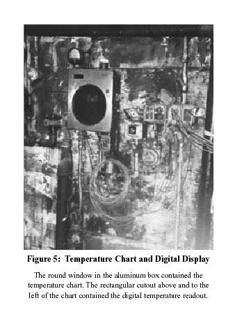
Every things under control High-Integrity Pressure Protection System (HIPPS)
") Every things under control www.adico.co info@adico.co Table Of Contents 1. Introduction... 2 2. Standards... 3 3. HIPPS vs Emergency Shut Down... 4 4. Safety Requirement Specification... 4 5. Device Integrity
Every things under control www.adico.co info@adico.co Table Of Contents 1. Introduction... 2 2. Standards... 3 3. HIPPS vs Emergency Shut Down... 4 4. Safety Requirement Specification... 4 5. Device Integrity
Basic STPA Exercises. Dr. John Thomas
 Basic STPA Exercises Dr. John Thomas Chemical Plant Goal: To produce and sell chemical X What (System): A chemical plant (production), How (Method): By means of a chemical reaction, a catalyst,. CATALYST
REPEATED ACCIDENT CAUSES CAN WE LEARN?
 REPEATED ACCIDENT CAUSES CAN WE LEARN? Peter Waite Technical Director, Entec UK Limited Over the last twenty years major process industry accidents have continued to occur despite the introduction of new
Process Safety Journey
 Process Safety Journey Agenda The Status in early 2000s The Journey to improvement in Process Safety management Managing risks and barriers How has this impacted Kwinana? The Status in early 2000s Focus
Purpose. Scope. Process flow OPERATING PROCEDURE 07: HAZARD LOG MANAGEMENT
 SYDNEY TRAINS SAFETY MANAGEMENT SYSTEM OPERATING PROCEDURE 07: HAZARD LOG MANAGEMENT Purpose Scope Process flow This operating procedure supports SMS-07-SP-3067 Manage Safety Change and establishes the
Solenoid Valves used in Safety Instrumented Systems
 I&M V9629R1 Solenoid Valves used in Safety Instrumented Systems Operating Manual in accordance with IEC 61508 ASCO Valves Page 1 of 7 Table of Contents 1 Introduction...3 1.1 Terms and Abbreviations...3
THE BAKER REPORT HOW FINDINGS HAVE BEEN USED BY JOHNSON MATTHEY TO REVIEW THEIR MANUFACTURING OPERATIONS
 THE BAKER REPORT HOW FINDINGS HAVE BEEN USED BY JOHNSON MATTHEY TO REVIEW THEIR MANUFACTURING OPERATIONS Colin P. Lynas, Elizabeth Campbell and Hendrik J. Koornhof Johnson Matthey Catalysts This paper
Safety Engineering - Hazard Identification Techniques - M. Jahoda
 Safety Engineering - Hazard Identification Techniques - M. Jahoda Hazard identification The risk management of a plant 2 Identification of the hazards involved in the operation of the plant, due to the
SIL explained. Understanding the use of valve actuators in SIL rated safety instrumented systems ACTUATION
 SIL explained Understanding the use of valve actuators in SIL rated safety instrumented systems The requirement for Safety Integrity Level (SIL) equipment can be complicated and confusing. In this document,
Lecture 04 ( ) Hazard Analysis. Systeme hoher Qualität und Sicherheit Universität Bremen WS 2015/2016
 Hazard Analysis. Systeme hoher Qualität und Sicherheit Universität Bremen WS 2015/2016") Systeme hoher Qualität und Sicherheit Universität Bremen WS 2015/2016 Lecture 04 (02.11.2015) Hazard Analysis Christoph Lüth Jan Peleska Dieter Hutter Where are we? 01: Concepts of Quality 02: Legal Requirements:
Systeme hoher Qualität und Sicherheit Universität Bremen WS 2015/2016 Lecture 04 (02.11.2015) Hazard Analysis Christoph Lüth Jan Peleska Dieter Hutter Where are we? 01: Concepts of Quality 02: Legal Requirements:
DeZURIK. KGC Cast Knife Gate Valve. Safety Manual
 KGC Cast Knife Gate Valve Safety Manual Manual D11036 August 29, 2014 Table of Contents 1 Introduction... 3 1.1 Terms... 3 1.2 Abbreviations... 4 1.3 Product Support... 4 1.4 Related Literature... 4 1.5
Safe management of industrial steam and hot water boilers A guide for owners, managers and supervisors of boilers, boiler houses and boiler plant
 Health and Safety Executive Safe management of industrial steam and hot water boilers A guide for owners, managers and supervisors of boilers, boiler houses and boiler plant Background Accidents involving
DeZURIK Double Block & Bleed (DBB) Knife Gate Valve Safety Manual
 Knife Gate Valve Safety Manual") Double Block & Bleed (DBB) Knife Gate Valve Safety Manual Manual D11044 September, 2015 Table of Contents 1 Introduction... 3 1.1 Terms... 3 1.2 Abbreviations... 4 1.3 Product Support... 4 1.4 Related
Double Block & Bleed (DBB) Knife Gate Valve Safety Manual Manual D11044 September, 2015 Table of Contents 1 Introduction... 3 1.1 Terms... 3 1.2 Abbreviations... 4 1.3 Product Support... 4 1.4 Related
DeZURIK. KSV Knife Gate Valve. Safety Manual
 KSV Knife Gate Valve Safety Manual Manual D11035 August 29, 2014 Table of Contents 1 Introduction... 3 1.1 Terms... 3 1.2 Abbreviations... 4 1.3 Product Support... 4 1.4 Related Literature... 4 1.5 Reference
A large Layer of Protection Analysis for a Gas terminal scenarios/ cause consequence pairs
 A large Layer of Protection Analysis for a Gas terminal 2000+ scenarios/ cause consequence pairs Richard Gowland European process Safety Centre The scope of the study was a large gas terminal handling
This manual provides necessary requirements for meeting the IEC or IEC functional safety standards.
 Instruction Manual Supplement Safety manual for Fisher Vee-Ball Series Purpose This safety manual provides information necessary to design, install, verify and maintain a Safety Instrumented Function (SIF)
A study on the relation between safety analysis process and system engineering process of train control system
 A study on the relation between safety analysis process and system engineering process of train control system Abstract - In this paper, the relationship between system engineering lifecycle and safety
Proof Testing A key performance indicator for designers and end users of Safety Instrumented Systems
 Proof Testing A key performance indicator for designers and end users of Safety Instrumented Systems EUR ING David Green BEng(hons) CEng MIET MInstMC RFSE Ron Bell OBE BSc CEng FIET Engineering Safety
RESILIENT SEATED BUTTERFLY VALVES FUNCTIONAL SAFETY MANUAL
 Per IEC 61508 and IEC 61511 Standards BRAY.COM Table of Contents 1.0 Introduction.................................................... 1 1.1 Terms and Abbreviations...........................................
Nitrogen System Contamination
 Nitrogen System Contamination Lessons Learned Volume 05 Issue 03 2005 USW Nitrogen System Contamination Purpose To conduct a small group lessons learned activity to share information gained from incident
Introducing STAMP in Road Tunnel Safety
 Introducing STAMP in Road Tunnel Safety Kostis Kazaras National Technical University of Athens, Mechanical Engineering School, Greece Contact details: kkazaras@gmail.com kkaz@central.ntua.gr Problem illustration
Systems Theoretic Process Analysis (STPA)
") Systems Theoretic Process Analysis (STPA) Systems approach to safety engineering (STAMP) STAMP Model (Leveson, 2012) Accidents are more than a chain of events, they involve complex dynamic processes. Treat
Systems Theoretic Process Analysis (STPA) Systems approach to safety engineering (STAMP) STAMP Model (Leveson, 2012) Accidents are more than a chain of events, they involve complex dynamic processes. Treat
The Relationship Between Automation Complexity and Operator Error
 The Relationship Between Automation Complexity and Operator Error presented by Russell Ogle, Ph.D., P.E., CSP rogle@exponent.com (630) 274-3215 Chemical Plant Control Control physical and chemical processes
FP15 Interface Valve. SIL Safety Manual. SIL SM.018 Rev 1. Compiled By : G. Elliott, Date: 30/10/2017. Innovative and Reliable Valve & Pump Solutions
 SIL SM.018 Rev 1 FP15 Interface Valve Compiled By : G. Elliott, Date: 30/10/2017 FP15/L1 FP15/H1 Contents Terminology Definitions......3 Acronyms & Abbreviations...4 1. Introduction...5 1.1 Scope.. 5 1.2
Incorrect Relief Valve Material Causes Release
 Incorrect Relief Valve Material Causes Release Lessons Learned Volume 04 Issue 18 2004 USW Purpose Incorrect Relief Valve Material Causes Release To conduct a small group lessons learned activity to share
BSR GPTC Z TR GM References and Reporting Page 1 of 8
 Page 1 of 8 PRIMARY: 192.605 SECONDARY: 191.23 PURPOSE: Review guide material added by TR 2009-17 to 5.1(e) and consider restructuring the guide material under 192.605 as discussed further below. ORIGIN/RATIONALE
Systems Theoretic Process Analysis (STPA)
") Systems Theoretic Process Analysis (STPA) 1 Systems approach to safety engineering (STAMP) STAMP Model Accidents are more than a chain of events, they involve complex dynamic processes. Treat accidents
Systems Theoretic Process Analysis (STPA) 1 Systems approach to safety engineering (STAMP) STAMP Model Accidents are more than a chain of events, they involve complex dynamic processes. Treat accidents
Proposed Abstract for the 2011 Texas A&M Instrumentation Symposium for the Process Industries
 Proposed Abstract for the 2011 Texas A&M Instrumentation Symposium for the Process Industries Focus Area: Automation HMI Title: Author: Shared Field Instruments in SIS: Incidents Caused by Poor Design
The Risk of LOPA and SIL Classification in the process industry
 The Risk of LOPA and SIL Classification in the process industry Mary Kay O Connor Process Safety Center International Symposium Beyond Regulatory Compliance, Making Safety Second Nature October 28-29,
Safety manual for Fisher GX Control Valve and Actuator
 Instruction Manual Supplement GX Valve and Actuator Safety manual for Fisher GX Control Valve and Actuator Purpose This safety manual provides information necessary to design, install, verify and maintain
Safety Manual VEGAVIB series 60
 Safety Manual VEGAVIB series 60 NAMUR Document ID: 32005 Contents Contents 1 Functional safety... 3 1.1 General information... 3 1.2 Planning... 4 1.3 Adjustment instructions... 6 1.4 Setup... 6 1.5 Reaction
Understanding safety life cycles
 Understanding safety life cycles IEC/EN 61508 is the basis for the specification, design, and operation of safety instrumented systems (SIS) Fast Forward: IEC/EN 61508 standards need to be implemented
Requirements for Reduced Supervision of Power Plants, Thermal Liquid Heating Systems, and Heating Plants
 the pressure equipment safety authority Requirements for Reduced Supervision of Power Plants, Thermal Liquid Heating Systems, and Heating Plants AB-528 Edition 2, Revision 1 Issued 2016-09-12 Table of
Pressure Systems Safety Regulation
 Pressure Systems Safety Regulation Introduction This document informs Faculty of the key requirements of the UK and Chinese Pressure Systems Safety regulations. The aim of these regulations is to prevent
Section 1: Multiple Choice
 CFSP Process Applications Section 1: Multiple Choice EXAMPLE Candidate Exam Number (No Name): Please write down your name in the above provided space. Only one answer is correct. Please circle only the
Safety-critical systems: Basic definitions
 Safety-critical systems: Basic definitions Ákos Horváth Based on István Majzik s slides Dept. of Measurement and Information Systems Budapest University of Technology and Economics Department of Measurement
Identification and Screening of Scenarios for LOPA. Ken First Dow Chemical Company Midland, MI
 Identification and Screening of Scenarios for LOPA Ken First Dow Chemical Company Midland, MI 1 Layers of Protection Analysis (LOPA) LOPA is a semi-quantitative tool for analyzing and assessing risk. The
Control Performance: An Imperative for Safety
 Control Performance: An Imperative for Safety George Buckbee 2014 ExperTune, a Metso Company Page 1 Control Performance: An Imperative for Safety George Buckbee, ExperTune 2014 ExperTune, a Metso Company
Reliability of Safety-Critical Systems Chapter 3. Failures and Failure Analysis
 Reliability of Safety-Critical Systems Chapter 3. Failures and Failure Analysis Mary Ann Lundteigen and Marvin Rausand mary.a.lundteigen@ntnu.no RAMS Group Department of Production and Quality Engineering
Eutectic Plug Valve. SIL Safety Manual. SIL SM.015 Rev 0. Compiled By : G. Elliott, Date: 19/10/2016. Innovative and Reliable Valve & Pump Solutions
 SIL SM.015 Rev 0 Eutectic Plug Valve Compiled By : G. Elliott, Date: 19/10/2016 Contents Terminology Definitions......3 Acronyms & Abbreviations...4 1. Introduction..5 1.1 Scope 5 1.2 Relevant Standards
TRI LOK SAFETY MANUAL TRI LOK TRIPLE OFFSET BUTTERFLY VALVE. The High Performance Company
 TRI LOK TRI LOK TRIPLE OFFSET BUTTERFLY VALVE SAFETY MANUAL The High Performance Company Table of Contents 1.0 Introduction...1 1.1 Terms and Abbreviations... 1 1.2 Acronyms... 1 1.3 Product Support...
SUP 15 Health & Safety Management Pressure Systems. Unified procedures for use within NHS Scotland
 SUP 15 Health & Safety Management Pressure Systems Unified procedures for use within NHS Scotland September 2015 Contents Page Acknowledgements... 3 1. Introduction... 4 2. Purpose of this Procedure...
Bespoke Hydraulic Manifold Assembly
 SIL SM.0003 1 Bespoke Hydraulic Manifold Assembly Compiled By : G. Elliott, Date: 12/17/2015 Contents Terminology Definitions......3 Acronyms & Abbreviations..4 1. Introduction 5 1.1 Scope 5 1.2 Relevant
Safety assessments for Aerodromes (Chapter 3 of the PANS-Aerodromes, 1 st ed)
") Safety assessments for Aerodromes (Chapter 3 of the PANS-Aerodromes, 1 st ed) ICAO MID Seminar on Aerodrome Operational Procedures (PANS-Aerodromes) Cairo, November 2017 Avner Shilo, Technical officer
Safety assessments for Aerodromes (Chapter 3 of the PANS-Aerodromes, 1 st ed) ICAO MID Seminar on Aerodrome Operational Procedures (PANS-Aerodromes) Cairo, November 2017 Avner Shilo, Technical officer
Lessons Learned from the Texas City Refinery Explosion Mike Broadribb
 Lessons Learned from the Texas City Refinery Explosion Mike Broadribb Mary Kay O Connor Process Safety Center Symposium, College Station, Texas October 24, 2006 Texas City Refinery Texas City refinery
Basic STPA Tutorial. John Thomas
 Basic STPA Tutorial John Thomas How is STAMP different? STAMP Model (Leveson, 2003); (Leveson, 2011) Accidents are more than a chain of events, they involve complex dynamic processes. Treat accidents as
 Title of Paper Interpretation of IP15 in Process Plant Design: a Commonsense Approach ---------------------------------------------------------------------------------------------------------------------------
NORMAL OPERATING PROCEDURES Operating Parameter Information
 Operating Parameter Information Each operator performing the normal operating procedures (routine checks) of the facility should be familiar with the current normal operating parameters of all systems
Safety Manual. Process pressure transmitter IPT-1* 4 20 ma/hart. Process pressure transmitter IPT-1*
 Safety Manual Process pressure transmitter IPT-1* 4 20 ma/hart Process pressure transmitter IPT-1* Contents Contents 1 Functional safety 1.1 General information... 3 1.2 Planning... 4 1.3 Instrument parameter
PSM TRAINING COURSES. Courses can be conducted in multi-languages
 Courses can be conducted in multi-languages One set of hardcopy course notes will be sent to client for printing and distribution to course participants. The courses will be held at the client s training
USING HAZOP TO IDENTIFY AND MINIMISE HUMAN ERRORS IN OPERATING PROCESS PLANT
 USING HAZOP TO IDENTIFY AND MINIMISE HUMAN ERRORS IN OPERATING PROCESS PLANT Chris Lyth, Tracerco, Billingham, Cleveland, UK Ian Bradby, ABB Engineering Services, Billingham Cleveland, UK This joint paper
Hazard Identification
 Hazard Identification Most important stage of Risk Assessment Process 35+ Techniques Quantitative / Qualitative Failure Modes and Effects Analysis FMEA Energy Analysis Hazard and Operability Studies HAZOP
Pigging as a Flow Assurance Solution Avoiding Slug Catcher Overflow
 Pigging as a Flow Assurance Solution Avoiding Slug Catcher Overflow Aidan O'Donoghue, Pipeline Research Limited, Glasgow, UK This paper sets out to provide an initial method of assessing the bypass requirements
Safety in Petroleum Industry
 Chemical ( Industrial ) Disaster Management Conference, Bangalore 30 January 2014 Safety in Petroleum Industry Refineries and Petrochemical plants are highly energyintensive Handle highly inflammable and
UNIVERSITY OF WATERLOO
 UNIVERSITY OF WATERLOO Department of Chemical Engineering ChE 524 Process Control Laboratory Instruction Manual January, 2001 Revised: May, 2009 1 Experiment # 2 - Double Pipe Heat Exchanger Experimental
Hydraulic (Subsea) Shuttle Valves
 Shuttle Valves") SIL SM.009 0 Hydraulic (Subsea) Shuttle Valves Compiled By : G. Elliott, Date: 11/3/2014 Contents Terminology Definitions......3 Acronyms & Abbreviations..4 1. Introduction 5 1.1 Scope 5 1.2 Relevant Standards
SIL SM.009 0 Hydraulic (Subsea) Shuttle Valves Compiled By : G. Elliott, Date: 11/3/2014 Contents Terminology Definitions......3 Acronyms & Abbreviations..4 1. Introduction 5 1.1 Scope 5 1.2 Relevant Standards
Significant Change to Dairy Heat Treatment Equipment and Systems
 Significant to Dairy Heat Treatment September 2008 Page 1 Significant to Dairy Heat Treatment Equipment and Systems September 2008 1 Background Requirements for the assessment of dairy heat treatment equipment
Process Safety Value and Learnings Central Valley Chemical Safety Day March 20, 2014
 Process Safety Value and Learnings Central Valley Chemical Safety Day March 20, 2014 Randy Bennett Sr. Staff Health & Safety Engineer Process Safety Management Group Aera Energy LLC Key Points Process
Modelling Today for the Future. Advanced Modelling Control Techniques
 CwMAG 1 st Autumn Conference 2012 Modelling Today for the Future Advanced Modelling Control Techniques What are advanced modelling controls? Why do we have them? How can we use them? What are the differences
Using Reliability Centred Maintenance (RCM) to determine which automated monitoring systems to install to new and existing equipment
 to determine which automated monitoring systems to install to new and existing equipment") Using Reliability Centred Maintenance (RCM) to determine which automated monitoring systems to install to new and existing equipment CHRIS JAMES RELIABILITY MANAGEMENT LTD Cairo, November 2018 The rate
Using Reliability Centred Maintenance (RCM) to determine which automated monitoring systems to install to new and existing equipment CHRIS JAMES RELIABILITY MANAGEMENT LTD Cairo, November 2018 The rate
Learning from Dangerous Occurrences in the Chemical Industries
 Learning from Dangerous Occurrences in the Chemical Industries John A. Hare, Richard J. Goff and Justin Holroyd Health and Safety Laboratory, Buxton, UK 1. Introduction It is important to learn lessons
Section 1: Multiple Choice Explained EXAMPLE
 CFSP Process Applications Section 1: Multiple Choice Explained EXAMPLE Candidate Exam Number (No Name): Please write down your name in the above provided space. Only one answer is correct. Please circle
4m Blanco Glycol Chiller system: history, recent events, present status and plans
 4m Blanco Glycol Chiller system: history, recent events, present status and plans Brooke Gregory, Esteban Parkes, Chris Smith 22 May 2012 Background Information: Original configuration (from ~1975) of
Solenoid Valves For Gas Service FP02G & FP05G
 SIL Safety Manual SM.0002 Rev 02 Solenoid Valves For Gas Service FP02G & FP05G Compiled By : G. Elliott, Date: 31/10/2017 Reviewed By : Peter Kyrycz Date: 31/10/2017 Contents Terminology Definitions......3
Safety & Health Division. INVESTIGATION INTO THE FATAL ACCIDENT TO JOHN ANTHONY MAHER AT COOK COLLIERY ON 30th AUGUST 2000
 INVESTIGATION INTO THE FATAL ACCIDENT TO JOHN ANTHONY MAHER AT COOK COLLIERY ON 30th AUGUST 2000 1 ACCIDENT SUMMARY Prior to the accident the continuous miner was immobilised in a sump when the left rib
Introduction to Emergency Response & Contingency Planning
 & Contingency Planning Rationale Why is it important for you to learn this material? Designed for those who may witness a release, this is an introductory course designed to help ensure those who are likely
Reliability of Safety-Critical Systems Chapter 10. Common-Cause Failures - part 1
 Reliability of Safety-Critical Systems Chapter 10. Common-Cause Failures - part 1 Mary Ann Lundteigen and Marvin Rausand mary.a.lundteigen@ntnu.no &marvin.rausand@ntnu.no RAMS Group Department of Production
LECTURE 3 MAINTENANCE DECISION MAKING STRATEGIES (RELIABILITY CENTERED MAINTENANCE)
") LECTURE 3 MAINTENANCE DECISION MAKING STRATEGIES (RELIABILITY CENTERED MAINTENANCE) Politecnico di Milano, Italy piero.baraldi@polimi.it 1 Types of maintenance approaches Intervention Unplanned Planned
LECTURE 3 MAINTENANCE DECISION MAKING STRATEGIES (RELIABILITY CENTERED MAINTENANCE) Politecnico di Milano, Italy piero.baraldi@polimi.it 1 Types of maintenance approaches Intervention Unplanned Planned
HUMAN FACTORS CHECKLIST
 HUMAN FACTORS CHECKLIST Item I. Housekeeping and General Work Environment 1 Are adequate signs posted near maintenance, cleanup, or staging areas to warn workers of special or unique hazards associated
Operator Exposed to Chlorine Gas
 Operator Exposed to Chlorine Gas Lessons Learned Volume 04 Issue 29 2004 USW Operator Exposed to Chlorine Gas Purpose To conduct a small group lessons learned activity to share information gained from
VALIDATE LOPA ASSUMPTIONS WITH DATA FROM YOUR OWN PROCESS
 Honeywell Advanced Materials new Low-Global-Warming Refrigerant Plant in Geismar, LA Tony Downes Sept 2018 VALIDATE LOPA ASSUMPTIONS WITH DATA FROM YOUR OWN PROCESS A little about the presenter 1 Led over
IMCA DP Station Keeping Bulletin 04/18 November 2018
 DP STATION KEEPING BULLETIN IMCA DP Station Keeping Bulletin 04/18 November 2018 The following event trees have been compiled from recent reports received by IMCA. The originators granted IMCA permission
FIRE PROTECTION. In fact, hydraulic modeling allows for infinite what if scenarios including:
 By Phil Smith, Project Manager and Chen-Hsiang Su, PE, Senior Consultant, Lincolnshire, IL, JENSEN HUGHES A hydraulic model is a computer program configured to simulate flows for a hydraulic system. The
PREDICTING HEALTH OF FINAL CONTROL ELEMENT OF SAFETY INSTRUMENTED SYSTEM BY DIGITAL VALVE CONTROLLER
 PREDICTING HEALTH OF FINAL CONTROL ELEMENT OF SAFETY INSTRUMENTED SYSTEM BY DIGITAL VALVE CONTROLLER Riyaz Ali FIELDVUE Business Development Manager Fisher Controls Int'l., LLC. Marshalltown, IA 50158
DETERMINATION OF SAFETY REQUIREMENTS FOR SAFETY- RELATED PROTECTION AND CONTROL SYSTEMS - IEC 61508
 DETERMINATION OF SAFETY REQUIREMENTS FOR SAFETY- RELATED PROTECTION AND CONTROL SYSTEMS - IEC 61508 Simon J Brown Technology Division, Health & Safety Executive, Bootle, Merseyside L20 3QZ, UK Crown Copyright
Implementing IEC Standards for Safety Instrumented Systems
 Implementing IEC Standards for Safety Instrumented Systems ABHAY THODGE TUV Certificate: PFSE-06-607 INVENSYS OPERATIONS MANAGEMENT What is a Safety Instrumented System (SIS)? An SIS is designed to: respond
Pneumatic QEV. SIL Safety Manual SIL SM Compiled By : G. Elliott, Date: 8/19/2015. Innovative and Reliable Valve & Pump Solutions
 SIL SM.0010 1 Pneumatic QEV Compiled By : G. Elliott, Date: 8/19/2015 Contents Terminology Definitions......3 Acronyms & Abbreviations..4 1. Introduction 5 1.1 Scope 5 1.2 Relevant Standards 5 1.3 Other
SPR - Pneumatic Spool Valve
 SIL SM.008 Rev 7 SPR - Pneumatic Spool Valve Compiled By : G. Elliott, Date: 31/08/17 Contents Terminology Definitions:... 3 Acronyms & Abbreviations:... 4 1.0 Introduction... 5 1.1 Purpose & Scope...
Series 3730 and Series 3731 EXPERTplus Valve Diagnostics with Partial Stroke Test (PST)
") Series 3730 and Series 3731 EXPERTplus Valve Diagnostics with Partial Stroke Test (PST) Application Positioner firmware for early detection of control valve faults giving maintenance recommendations. Valid
Series 3730 and Series 3731 EXPERTplus Valve Diagnostics with Partial Stroke Test (PST) Application Positioner firmware for early detection of control valve faults giving maintenance recommendations. Valid
2600T Series Pressure Transmitters Plugged Impulse Line Detection Diagnostic. Pressure Measurement Engineered solutions for all applications
 Application Description AG/266PILD-EN Rev. C 2600T Series Pressure Transmitters Plugged Impulse Line Detection Diagnostic Pressure Measurement Engineered solutions for all applications Increase plant productivity
Advanced LOPA Topics
 11 Advanced LOPA Topics 11.1. Purpose The purpose of this chapter is to discuss more complex methods for using the LOPA technique. It is intended for analysts who are competent with applying the basic
Unit 5: Prioritize and Manage Hazards and Risks STUDENT GUIDE
 : Prioritize and Manage Hazards and Risks STUDENT GUIDE Objectives By the end of this unit, students will be able to: Describe several techniques that can be used to prioritize hazards for mitigation,
OIL AND GAS INDUSTRY
 This case study discusses the sizing of a coalescer filter and demonstrates its fouling life cycle analysis using a Flownex model which implements two new pressure loss components: - A rated pressure loss
OPERATING PROCEDURES
 OPERATING PROCEDURES 1.0 Purpose This element identifies Petsec s Operating Procedures for its Safety and Environmental Management System (SEMS) Program; it applies to all Petsec operations. Petsec is
CASE STUDY. Compressed Air Control System. Industry. Application. Background. Challenge. Results. Automotive Assembly
 Compressed Air Control System Industry Automotive Assembly Application Savigent Platform and Industrial Compressed Air Systems Background This automotive assembly plant was using over 40,000 kilowatt hours
Failure Modes, Effects and Diagnostic Analysis
 Failure Modes, Effects and Diagnostic Analysis Project: Abc. X Series Ball Valve Company: Abc. Inc. Sellersville, PA USA Contract Number: Q11/12-345 Report No.: Abc 11/12-345 R001 Version V1, Revision
SEMS II: BSEE should focus on eliminating human error
 SEMS II: BSEE should focus on eliminating human error How US companies can prevent accidents on start-ups and shut-downs by using valve interlocks The proposed changes to BSEE s SEMS (Safety and Environmental
Session One: A Practical Approach to Managing Safety Critical Equipment and Systems in Process Plants
 Session One: A Practical Approach to Managing Safety Critical Equipment and Systems in Process Plants Tahir Rafique Lead Electrical and Instruments Engineer: Qenos Botany Site Douglas Lloyd Senior Electrical
Workshop Functional Safety
 Workshop Functional Safety Nieuwegein 12 March 2014 Workshop Functional Safety VDMA 4315 Part 1 page 1 Agenda VDMA Working Group on Functional Safety Functional Safety and Safety Lifecycle Functional Safety
Safety Manual VEGAVIB series 60
 Safety Manual VEGAVIB series 60 Contactless electronic switch Document ID: 32002 Contents Contents 1 Functional safety... 3 1.1 General information... 3 1.2 Planning... 4 1.3 Adjustment instructions...
A Continued Worker Safety Issue
 The petroleum industry has undertaken a voluntary environmental performance tracking initiative, recording detailed information about spills and releases, their causes and consequences. The members of
FRDS GEN II SIMULATOR WORKBOOK
 FRDS GEN II SIMULATOR WORKBOOK Trotter Control Inc 2015 Document# Revision Revised 9001-0038 FRDS GEN II Simulator Workbook E 02/15/2015 by DC FRDS GEN II Simulator Workbook This workbook is a follow-on
PROCESS SAFETY FUNDAMENTAL #1 Always use two barriers for hydrocarbon and chemical drains & vents
 #1 Always use two barriers for hydrocarbon and chemical drains & vents This applies to vents and drains, not every isolation. Continue to follow current Permit to Work process and guidance from PtW focal
Technical Standards and Legislation: Risk Based Inspection. Presenter: Pierre Swart
 Technical Standards and Legislation: Risk Based Inspection Presenter: Pierre Swart Agenda Change in Legislation. Where RBI fits in. Application to implement RBI. RBI concepts. Elements of an RBI analysis.
Understanding the How, Why, and What of a Safety Integrity Level (SIL)
") Understanding the How, Why, and What of a Safety Integrity Level (SIL) Audio is provided via internet. Please enable your speaker (in all places) and mute your microphone. Understanding the How, Why, and
Understanding the How, Why, and What of a Safety Integrity Level (SIL) Audio is provided via internet. Please enable your speaker (in all places) and mute your microphone. Understanding the How, Why, and
Management of Change (MOC) Could Have Prevented Death
 Could Have Prevented Death") Management of Change (MOC) Could Have Prevented Death Lessons Learned Volume 03 Issue 16 2004 USW Management of Change (MOC) Could Have Prevented Death Purpose To conduct a small group lessons learned
Management of Change (MOC) Could Have Prevented Death Lessons Learned Volume 03 Issue 16 2004 USW Management of Change (MOC) Could Have Prevented Death Purpose To conduct a small group lessons learned
Hazard Operability Analysis
 Hazard Operability Analysis Politecnico di Milano Dipartimento di Energia HAZOP Qualitative Deductive (search for causes) Inductive (consequence analysis) AIM: Identification of possible process anomalies
Delayed Coker Automation & Interlocks
 Delayed Coker Automation & Interlocks a Presented by Mitch Moloney of ExxonMobil @ coking.com April-2005 MJ Moloney - ExxonMobil April-2005 coking.com 0 Automation & Interlocks @ ExxonMobil - Background
Using STPA in the Design of a new Manned Spacecraft
 Using STPA in the Design of a new Manned Spacecraft Japan Aerospace Exploration Agency (JAXA) Ryo Ujiie 1 Contents Abstract Purpose JAXA s Manned Spacecraft (CRV) JAXA s Experience of STPA STPA in CRV
High Integrity Pressure Protection Systems HIPPS
 High Integrity Pressure Protection Systems HIPPS HIPPS > High Integrity Pressure Protection Systems WHAT IS A HIPPS The High Integrity Pressure Protection Systems (HIPPS) is a mechanical and electrical