1 Introduction on the appearance, configuration and function
|
|
|
- Rebecca Robinson
- 5 years ago
- Views:
Transcription
1 1 Introduction on the appearance, configuration and function 1.1 Appearance of ALICE hemodialysis unit -1-
2 Front Back Left side Right side -2-

3 1.2 Configuration and function of ALICE hemodialysis unit Operation interface with LCD touch screen High-resolution LCD touch screen with display of time and date, dynamicly displays the running and treatment condition of blood pipeline and dialysate. Dialysis Stopped Lower Conductivity Alam Blood Level Alarm TMP. A.P. V.P. Battery Blood Leak Blood Level Air Bubble Heparin Clogging Temp. Cond mmhg mmhg mmhg 0 UF Rate Heparin Time Time Left Temp ml/h 3: :59 UF Volume Heparin Flux Na+ ml UF Goal ml Blood pump ml/h ml/min mmol/l Adjust Spare Pump ml/min ms/cn Blood p. Heparin UF P. Spare P. Bypass Extracorporeal cycle power and monitor system Blood pump and spare pump Run Bridging Retuen Setting Fig. 1-1 High precision dual pumps setting. Lineal adjustment of blood pump flow rate is available. Tube of Φ6mm achieves a flowrate of 15 ~ 340 ml/min, and tube of Φ8mm achieves one of 20 ~ 460 ml/min. Pump rate monitor system (real-time detection of pump rate and feedback to system for adjustment) offers accurate blood flow rate and power for extracorporeal cycle. In case of blood pump pump failure, the spare pump can be switched for MON 15:03 Fig. 1-2 be switched for dialysis by operation, which ensures a continuous dialysis before the arrival of maintenance technician. In addition, the spare pump can cooperate with the blood pump for easy blood filtration treatment Heparin pump -3-

4 Dual heparin pump setting with a pump rate of 0.1~10ml/hr, which is suitable for syringe of 20ml, 30ml, and 50ml, with the function of empty, block and timing alarm. The flow pump is used for the adjustment of the concentration of electrolyte, such as sodium and potassium, as well as the slow clinical injection of venous medicine. The heparin pump and the flow pump can also be switched. Fig Dynamic display of A.P, V.P, TMP and conductivity in the same interface. TMP. A.P. V.P. Cond mmhg mmhg mmhg ms/cn Fig. 1-4 Fig Electronic blood-pressure meter Each unit is equipped with electronic blood-pressure meter, which conveniences the operator to learn about the blood pressure and pulse of the patient anytime. Fig Dialysate supply system Automatic confection system As long as the RO water and concentrate are supplied, the automatic confection system will dilute them into standard dialysate.according to the preset proportion, four pre-set standards in the machine which are Fresenius, Baxter, Gambro, and Toray repectively are available for selection. -4-

5 Concentration of sodium Adjustable sodium dialysis: The concentration of sodium ion can be set in the control panel. The unit will change the proportion of the concentrate and RO water, to alternate the concentrate of sodium in the dialysate, which ensures a dialysis of adjustable sodium. Na+ 140 mmol/l Fig. 1-7 Adjust Multiple conductivity monitor system (a) With monitor in sucking concentration A and B,which prevent Pot A and Pot B are exchanged in operation. (b) After collocation is finished and the temperature of dialysate is rised, the gas can be prevented being volatilized and the conductivity shall be tested again. (c) Before transfusing the dialysate to the dialyzer, in case the conductivity exceed the normal range, the dialysate shall be abandoned from the bypass to make sure only standard dialysate can enter the dialyzer. Fig With the temperature monitot and the heat system to ensure the temperature of dialysate reaches the required (a) The inlet of RO water has a heat exchanger to allow a heat exchange between the heated evacuation and the incoming RO water, which benefit the heating of RO water and the stability of dialysate temperature. (b) The heating chamber has double safety insurance of temperature monitor and High Temperature safety switch. When the fluid is heated to the preset temperature, the temperature probe sends the feedback to the system to stop heating. In case the heating is out of control, the High Temperature safety switch will automatically break off the power supply to ensure the safety. of control, the High Temperature safety switch will automatically break off the power supply to -5- Fig. 1-9
6 ensure the safety. (c) Before transfusing the dialysate to the dialyzer, the temperature inspection is increased and the upper and lower alarm temperaute can be set such as if the temperature exceeds the upper or lower limit, abandon the dialysate from the bypass, then the accident due to the abnormal temperature of the dialysate can be prevented. -6-
7 1.2.4 Waterway balance control and UF control The waterway flow control can be achieved by volume balance and volume UF two ways The flow rate of dialysate can be adjusted in a linear way (300~800 ml/min) on the panel, which allows a free selection of the flow rate according to the condition of the patient. A high-volume dialysis can be made to achieve a higher performance. Dialysis Flux 500 ml/min Fig The independent UF control panel allows an easy control of UF. The precision of dehydration can reach to 1ml/sec and the UF rate can be 0 ~ 1800 ml/hr with resolution of 1ml. UF Rate 0010 ml/h UF Volume 0000 ml UF Goal 0000 ml Fig With the function of UF test, it is available to examine the accuracy of UF at anytime Blood leakage monitor Photoelectric principle is used in the blood leakage detection that alarm can be triggered in a mixture of 1 ml blood in 1 liter of dialysate, which corresponds that it can be detected when 1 piece of hollow fiber breaks in 1 dialyzer. Fig Automatic disinfection function To prevent the cross contamination, the waterway adopts the way of one way drainage discharged to keep the tube clean. The used evacuation is directly discharged out of the unit. A fully automatic disinfection (chemical disinfection and heat disinfection) function is adopted that if the patient treatment is made in the am and pm shift, select the rinse button to start a 10-minute automatic rinse is OK. The disinfection inlet is equipped with temperature and conductivity inspection to remind using correct disinfection fluid. -7-
8 1.2.7 Treatment mode This unit can be used without the presence of water processing system. The main unit of the water supply box can automatically obtain water from the water tank for bedside hemodialysis, which is suitable for ICU hemodialysis treatment. It can also be used for treatment such as pure UF, hemoperfusion, plasma exchange (PE), and hemofiltration This unit can be used with central dialysate and disinfection fluid supply system Spare power(optional) This unit has a spare power supply, which gets automatically charged when the unit is in use. In case of power cut, the unit will switch to the spare power supply automaticly, which can last for 30 minutes for operator to resume the power supply or end the treatment UF profile and Na + profile Prime This unit has the function of programmable UF and Stopped Na+(mmol/l) Na+ Curve adjustable sodium dialysis, which is able to effectively 160 Time Left 4: prevent the complications such as hypotension and 145 UF Rate 1800 ml/h 140 UF Goal ml muscle cramp. During the whole process of HD, UF with UF Volume 0000 ml 120 TIME constant speed is not necessarily the best option to (h) V.P mmhg UF Rate(ml/h) UF Curve 2000 TMP 0503 mmhg remove the water, as hypotension may occur in some Na mmol/l patients. The combination of programmable UF and Cond ms/cm 800 adjustable sodium HD of this unit (7 sodium curves and Temp UF curves are available for selection) can remove the 0 TIME (h) Return to Menu excrescent water at the beginning of HD and enhances Fig the concentrate of sodium ion of the dialysate, and the 7 UF curves are available for selection) can remove the excrescent water at the beginning of HD osmotic pressure in the vessel. It extracts the excessive water and enhances from the the texture concentrate into the of sodium vessel, ion and of then dialysate, and the osmotic pressure in the gradually vessel. It extracts reduces the the excessive UF volume water and from decreases the texture the into the vessel, and then gradually reduces concentrate of the sodium ion in the dialysate to reach the UF volume and decreases the concentrate of the sodium ion in the dialysate to reach the the optimal UF goal, avoiding the incurrence of hypotension. optimal UF goal, avoiding the incurrence of hypotension HCO 3- curve This unit has the function of HCO 3- curve, which is able to select the curve time and ion concentrate as per the condition of the patient, better rectifying the acidosis. Prime Stopped HCO3-(mmol/l) HCO3- SetUp STANDARD: TIME(H) KEY <- -> HCO3-038 mmol/l Run Time 200 min Fig Rerurn OK -8-
9 Bypass This unit has a bypass button, which allows the dialysate to go through the bypass instead of he dialyzer, after being pressed down. Bypass MON 15:03 Fig Waterway system principle drawing and description 2.1 Waterway system principle drawing D20 Degassing pump of fluid-supply chamber DS2CT6 Disinfection conductance and temperature base C12 AB steel tube D24 A\B degassing pump C23 Overflow valve 1 D31 Fluid A removing valve D32 Fluid B removing valve D22 Supply chamber air-removing valve DS1CT3 Mixed conductance and temperature base D1 Rinsing valve C13 AB steel tube D23 Inlet valve of disinfection 1 C16 Ventitation port (6207B-0) C2 Single way valve 2 F3 F1 F6 F5 C14 Disinfection 2 adapter (6207B-0) C35 Filter(400) Outlet 1 C1 Single way valve 1 Cycle pump P1 Fluid B pump JP3 Fluid A pump LM35 Inlet 1 Inlet 2 Outlet 2 in out in out CT2 Heating chamber 1 LM35 C27 Smalldiameter adapter CT7 Heating chamber 2 Circling air-removing chamber DS4CT1 Mixture chamber C7 Single way valve 7 Fluid A chamber Fluid B chamber Floater supply chamber C25 Heater DS5CT5 Post-dialysis conductance and temperature base C5 Single way valve 5 D13 D17 C24 Overflow valve 2 D18 D14 C30 Balance chamber group II C4 Single way valve 4 D16 D12 D11 D15 CP1 Pressure testing seat C11 Dialyzer return adapter (6207-0) C29 Balance chamber group I C32 Filter(400) C38 Fluid-return rapid adapter C37 Fluid-supply rapid adapter Dialyzer Disinfection 1 C42 C33 Filter(400) C17 Fluid A adapter (6207B-0) C18 Fluid B adapter (6207B-0) C34 Filter(400) C3 Single way valve 3 JP2 UF pump JP4 in out in UF pump out JP1 C21 Filter(400) D21 Inlet valve of fluid-supply D10 Bypass valve DS3CT4 Cond. and temp. of water-out D8 Pre-dialysis valve 1 C10 Fluid-supply adapter D9 Pre-dialysis valve 2 (6207-0) C39 Floater viewer C31 Filter(400) C45 (6207-0) A C40 B C41 C19 UF sample adapter (6207B-0) C20 Outlet of evacuation (6214-0) D19 UF outlet valve D02 UF sample valve P2 Post-dialysis pump C6 Single way valve 6 DB1 Blood leak inspector C26 Heat exchanger -9- Fig 2-1 D30 Water-in septum pump C47 Single way valve 47 C22 Filter(400) C44 (6207-0) D5 Disinfection cycle pump D7 Fluid-supply valve C8 Touch adapter (6205-0C) C9 Touch adapter (6205-0C) C28 Decompression valve RO Water inlet Pyrogen filter D3 Pyrogen filtration valve C46 (6207-0)
10 List of all parts of the water way connection diagram NO. Code of schematic diagram Name of parts Model Remark 1 C1 Single way valve A-0 2 C2 Single way valve A-0 3 C3 Single way valve A-0 4 C4 Single way valve A-0 5 C5 Single way valve A-0 6 C6 Single way valve A-0 7 C7 Single way valve A-0 8 C8 Touch adapter C9 Touch adapter C10 Dialysate-supply adapter C11 Dialysate-return adapter C12 AB steel tube C13 AB steel tube C14 Disinfection fluid 1 adapter 6207B-0 15 C16 Ventitation port 6207B-0 16 C17 Fluid A adapter 6207B-0 17 C18 Fluid B adapter 6207B-0 18 C19 UF sampling adapter 6207B-0 19 C20 Outlet of evacuation C21 Filter (250) C22 Filter (250) C23 Overflow valve A-0 23 C24 Overflow valve A-0 24 C25 Heater H-0E 25 C26 Heat exchanger A-0 26 C27 Small-diameter adapter C28 Decompression valve 5204A-0 RO water inlet 28 C29 Balance chamber group I I-0 29 C30 Balance chamber group II I-0 30 C31 Filter (400) C32 Filter (400)
11 32 C33 Filter (400) C34 Filter (400) C35 Filter (400) C36 Filter (400) C37 Dialyzer supply rapid adapter C38 Dialyzer return rapid adapter C39 Bobber viewer C40 Glue tank of fluid A --- Specification 10L 40 C41 Glue tank of fluid B C42 Glue tank of disinfection fluid Specification 10L 42 C44 Adapter C45 Adapter C46 Adapter C47 Single way valve A-0 46 CP1 Pressure testing seat CT2 Temperature detector of heating chamber 48 CT7 Temperature detector of heating chamber 2 LM35 LM35 49 D1 Rinse valve D2 UF sampling valve Without D3 D5 D6 51 D3 Pyrogen filtration valve D4 Inlet valve of disinfection D5 Disinfection cycle pump D7 Dialysate-supply valve D8 Pre-dialysis valve D9 Pre-dialysis valve D10 Bypass valve D11 Balance chamber E valve A 59 D12 Balance chamber F valve B 60 D13 Balance chamber G valve A 61 D14 Balance chamber H valve B 62 D15 Balance chamber A valve B 63 D16 Balance chamber B valve A 64 D17 Balance chamber C valve B -11-
12 65 D18 Balance chamber D valve A 66 D19 Outlet valve of UF D20 Air-removing valve of substitution chamber D21 Substitution inlet valve D22 Air-removing valve of substitution chamber D23 Disinfection fluid 1inlet valve D24 A\B air-removing pump Without D25~D29 72 D30 Water inlet septum pump DP D31 Fluid A air-removing valve D32 Fluid B air-removing valve DB1 Blood leakage inspector DS1CT3 Mixed conductance and temperature base 77 DS2CT6 Disinfection conductance and temperature base 78 DS3CT4 Outlet conductance and temperature base 79 DS4CT1 Fluid A conductance and temperature base 80 DS5CT5 Post-dialysis conductance and temperature base 81 F1 Blood level switch of fluid A chamber 82 F3 Blood level switch of heating chamber 83 F5 Blood level switch of Substitution chamber F -0C F -0C F -0C F -0C F -0C FASF-42LP-1A1 FASF-42LP-1A1 FASF-42LP-1A1 84 F6 Blood level switch of fluid B FASF-42LP-1A1 chamber 85 JP1 UF pump Proportional pump 86 JP2 Pump A JP3 Pump B P1 Cycling pump 3102A-0 Gear pump 89 P2 Post-dialysis pump 3102A-0-12-
13 2.2 Description of waterway system principle drawing D20 Degassing pump of fluid-supply chamber DS2CT6 Disinfection conductance and temperature base C12 AB steel tube D24 A\B degassing pump C23 Overflow valve 1 D31 Fluid A removing valve D32 Fluid B removing valve D22 Supply chamber air-removing valve DS1CT3 Mixed conductance and temperature base D1 Rinsing valve C13 AB steel tube D23 Inlet valve of disinfection 1 C16 Ventitation port (6207B-0) C2 Single way valve 2 F3 F1 F6 F5 C14 Disinfection 2 adapter (6207B-0) C35 Filter(400) Outlet 1 C1 Single way valve 1 Cycle pump P1 Fluid B pump JP3 Fluid A pump LM35 Inlet 1 Inlet 2 Outlet 2 in out in out CT2 Heating chamber 1 LM35 C27 Smalldiameter adapter CT7 Heating chamber 2 Circling air-removing chamber DS4CT1 Mixture chamber C7 Single way valve 7 Fluid A chamber Fluid B chamber Floater supply chamber C25 Heater DS5CT5 Post-dialysis conductance and temperature base C5 Single way valve 5 D13 D17 C24 Overflow valve 2 D18 D14 C30 Balance chamber group II C4 Single way valve 4 D16 D12 D11 D15 CP1 Pressure testing seat C11 Dialyzer return adapter (6207-0) C29 Balance chamber group I C32 Filter(400) C38 Fluid-return rapid adapter C37 Fluid-supply rapid adapter Dialyzer Disinfection 1 C42 C33 Filter(400) C17 Fluid A adapter (6207B-0) C18 Fluid B adapter (6207B-0) C34 Filter(400) C3 Single way valve 3 JP2 UF pump JP4 in out in UF pump out JP1 C21 Filter(400) D21 Inlet valve of fluid-supply D10 Bypass valve DS3CT4 Cond. and temp. of water-out D8 Pre-dialysis valve 1 C10 Fluid-supply adapter D9 Pre-dialysis valve 2 (6207-0) C39 Floater viewer C31 Filter(400) C45 (6207-0) A C40 B C41 C19 UF sample adapter (6207B-0) C20 Outlet of evacuation (6214-0) D19 UF outlet valve D02 UF sample valve P2 Post-dialysis pump C6 Single way valve 6 DB1 Blood leak inspector C26 Heat exchanger D30 Water-in septum pump C47 Single way valve 47 C22 Filter(400) C44 (6207-0) D5 Disinfection cycle pump D7 Fluid-supply valve C8 Touch adapter (6205-0C) C9 Touch adapter (6205-0C) C28 Decompression valve RO Water inlet Pyrogen filter D3 Pyrogen filtration valve C46 (6207-0) Fig
14 Description of RO water entering the HD unit: (as Fig. 2-2 display of ) RO water enters from the inlet go through decompression valve (C28) to allow the water pressure to be 0.12MPa supply valve (D7) filter (C22) Inlet septum pump (D30) Heat exchanger (C26) allows the RO water and evacuation going through the banlance chamber (C29, C30) and blood leakage detector (DB1) to conduct heat exchange in the heat exchanger There is heat stick in the heating chamber (C25 left 1) for the heating of RO water. After being transfused from the heating chamber, the RO water mixes with fluid A before entering the heating chamber 2 (C25 left 2) Heating chamber 2 (C25 left 2) allows the gas generated from heating to evacuate from the ventilation port (C16) Cycling pump (P1) Cycling air-removing chamber (C25 left 3) connects to overflow valve (C23), which returns to heating chamber 2 through the overflow valve in case of increase of the pressure in the chamber. Fluid A mixture conductivity (DS4CT1) mixes fluid B mixture chamber (C25 left 4). -14-
15 2.3 Description of fluid A and B access entering the unit D20 Degassing pump of fluid-supply chamber DS2CT6 Disinfection conductance and temperature base C12 AB steel tube D24 A\B degassing pump C23 Overflow valve 1 D31 Fluid A removing valve D32 Fluid B removing valve D22 Supply chamber air-removing valve DS1CT3 Mixed conductance and temperature base D1 Rinsing valve C13 AB steel tube D23 Inlet valve of disinfection 1 C16 Ventitation port (6207B-0) C2 Single way valve 2 F3 F1 F6 F5 C14 Disinfection 2 adapter (6207B-0) C35 Filter(400) Outlet 1 C1 Single way valve 1 Cycle pump P1 Fluid B pump JP3 Fluid A pump LM35 Inlet 1 Inlet 2 Outlet 2 in out in out CT2 Heating chamber 1 LM35 C27 Smalldiameter adapter CT7 Heating chamber 2 Circling air-removing chamber DS4CT1 Mixture chamber C7 Single way valve 7 Fluid A chamber Fluid B chamber Floater supply chamber C25 Heater DS5CT5 Post-dialysis conductance and temperature base C5 Single way valve 5 D13 D17 C24 Overflow valve 2 D18 D14 C30 Balance chamber group II C4 Single way valve 4 D16 D12 D11 D15 CP1 Pressure testing seat C11 Dialyzer return adapter (6207-0) C29 Balance chamber group I C32 Filter(400) C38 Fluid-return rapid adapter C37 Fluid-supply rapid adapter Dialyzer Disinfection 1 C42 C33 Filter(400) C17 Fluid A adapter (6207B-0) C18 Fluid B adapter (6207B-0) C34 Filter(400) C3 Single way valve 3 JP2 UF pump JP4 in out in UF pump out JP1 C21 Filter(400) D21 Inlet valve of fluid-supply D10 Bypass valve DS3CT4 Cond. and temp. of water-out D8 Pre-dialysis valve 1 C10 Fluid-supply adapter D9 Pre-dialysis valve 2 (6207-0) C39 Floater viewer C31 Filter(400) C45 (6207-0) A C40 B C41 C19 UF sample adapter (6207B-0) C20 Outlet of evacuation (6214-0) D19 UF outlet valve D02 UF sample valve P2 Post-dialysis pump C6 Single way valve 6 DB1 Blood leak inspector C26 Heat exchanger D30 Water-in septum pump C47 Single way valve 47 C22 Filter(400) C44 (6207-0) D5 Disinfection cycle pump D7 Fluid-supply valve C8 Touch adapter (6205-0C) C9 Touch adapter (6205-0C) C28 Decompression valve RO Water inlet Pyrogen filter D3 Pyrogen filtration valve C46 (6207-0) Fig
16 Description of fluid A access entering the unit: (as Fig. 2-3 display of ) Fluid A enters the unit from adapter A (C17) Fluid A chamber (C25 left 5) connects A/B airremoving pump (D24) to remove the air from the sucked fluid A. Pump A (JP2) Fluid A mixes with the RO water transfused from the heating chamber (C25 left 1) and enters heating chamber 2 (C25 left 2). Description of fluid B access entering the unit: (as Fig.2-3 display of ) Fluid B enters the unit from adapter B (C18) Fluid B chamber (C25 left 6) connects A/B airremoving pump (D24) to remove the air from the sucked fluid B. Pump B (JP3) In the mixture chamber (C25 left 4), fluid B fully mixes with fluid A and RO water transfusing from the cycling air-removing chamber (C25 left 3) to be the dialysate. Mixture conductivity and temperature (DS1CT3) Banlance Chamber (C29, C30). -16-
17 2.4 Description of waterway system principle drawing D20 Degassing pump of fluid-supply chamber DS2CT6 Disinfection conductance and temperature base C12 AB steel tube D24 A\B degassing pump C23 Overflow valve 1 D31 Fluid A removing valve D32 Fluid B removing valve D22 Supply chamber air-removing valve DS1CT3 Mixed conductance and temperature base D1 Rinsing valve C13 AB steel tube D23 Inlet valve of disinfection 1 C16 Ventitation port (6207B-0) C2 Single way valve 2 F3 F1 F6 F5 C14 Disinfection 2 adapter (6207B-0) C35 Filter(400) Outlet 1 C1 Single way valve 1 Cycle pump P1 Fluid B pump JP3 Fluid A pump LM35 Inlet 1 Inlet 2 Outlet 2 in out in out CT2 Heating chamber 1 LM35 C27 Smalldiameter adapter CT7 Heating chamber 2 Circling air-removing chamber DS4CT1 Mixture chamber C7 Single way valve 7 Fluid A chamber Fluid B chamber Floater supply chamber C25 Heater DS5CT5 Post-dialysis conductance and temperature base C5 Single way valve 5 D13 D17 C24 Overflow valve 2 D18 D14 C30 Balance chamber group II C4 Single way valve 4 D16 D12 D11 D15 CP1 Pressure testing seat C11 Dialyzer return adapter (6207-0) C29 Balance chamber group I C32 Filter(400) C38 Fluid-return rapid adapter C37 Fluid-supply rapid adapter Dialyzer Disinfection 1 C42 C33 Filter(400) C17 Fluid A adapter (6207B-0) C18 Fluid B adapter (6207B-0) C34 Filter(400) C3 Single way valve 3 JP2 UF pump JP4 in out in UF pump out JP1 C21 Filter(400) D21 Inlet valve of fluid-supply D10 Bypass valve DS3CT4 Cond. and temp. of water-out D8 Pre-dialysis valve 1 C10 Fluid-supply adapter D9 Pre-dialysis valve 2 (6207-0) C39 Floater viewer C31 Filter(400) C45 (6207-0) A C40 B C41 C19 UF sample adapter (6207B-0) C20 Outlet of evacuation (6214-0) D19 UF outlet valve D02 UF sample valve P2 Post-dialysis pump C6 Single way valve 6 DB1 Blood leak inspector C26 Heat exchanger D30 Water-in septum pump C47 Single way valve 47 C22 Filter(400) C44 (6207-0) D5 Disinfection cycle pump D7 Fluid-supply valve C8 Touch adapter (6205-0C) C9 Touch adapter (6205-0C) C28 Decompression valve RO Water inlet Pyrogen filter D3 Pyrogen filtration valve C46 (6207-0) Fig
18 Description on dialysate and evacuation access: (as Fig. 2-4 display of ) Dialysate outputs from the mixture chamber (C25 left 4) Banlance Chamber (C29, C30), which is separated into two chambers by a swinging septum. The dialysate enters to the chamber of dialysate and the evacuation enters the chamber of evacuation, ensuring the volume of the incoming dialysate equals that of the discharged evacuation. Outlet conductivity and temperature (DS3CT4) Bypass valve (D10). If the temperature or conductivity of the dialysate is not stable, then the pre-dialysis valve 1 (D8) and pre-dialysis valve 2 (D9) close. The dialysate and evacuation are discharged from the unit through the bypass valve (D10). Pre-dialysis valve 1 (D8), and pre -dialysis Valve (D9) If the temperature and conductivity of the dialysate is stable, then the pre-dialysis (D8) and pre-dialysis valve (D9) will be open. Connect to adapter of dialysate-supply (C10) Dialysate enters into dialyzer Connect to adapter of dialysate-return fluid (C11) System pressure (CP1) monitors the transmembrane pressure (TMP) Post-dialysis conductivity and post-dialysis temperature (DS5CT5) Bobber dialysate-supply chamber (C25 left 7) connects to the air-removing pump (D20) of dialysate-supply chamber.when the blood level declines in the bobber dialysate-supply chamber, the air-removing pump will remove the air, drawing off the evacuation discharged from the banlance chamber (C29, C30) to the bobber dialysate-supply chamber, to ensure the sufficient supply of evacuation in the chamber UF pump (JP1) UF outlet valve (D19) Post-dialysis pump (P2) UF sampling pump (D02) Connect to outlet of evacuation (C20) Banlance chamber (C29, C30) Connect to UF sampling adapter (C19) Blood leakage detector (DB1) Heat exchanger (C26) Connect to outlet of evacuation(c20) -18-
19 2.5 Description of waterway system principle drawing D20 Degassing pump of fluid-supply chamber DS2CT6 Disinfection conductance and temperature base C12 AB steel tube D24 A\B degassing pump C23 Overflow valve 1 D31 Fluid A removing valve D32 Fluid B removing valve D22 Supply chamber air-removing valve DS1CT3 Mixed conductance and temperature base D1 Rinsing valve C13 AB steel tube D23 Inlet valve of disinfection 1 C16 Ventitation port (6207B-0) C2 Single way valve 2 F3 F1 F6 F5 C14 Disinfection 2 adapter (6207B-0) C35 Filter(400) C33 Filter(400) C17 Fluid A adapter (6207B-0) C18 Fluid B adapter (6207B-0) C34 Filter(400) C3 Single way valve 3 Outlet 1 C1 Single way valve 1 Cycle pump P1 Fluid B pump JP3 Fluid A pump JP2 UF pump JP4 LM35 Inlet 1 Inlet 2 Outlet 2 in out in out in out in UF pump out JP1 CT2 Heating chamber 1 LM35 C27 Smalldiameter adapter CT7 Heating chamber 2 Circling air-removing chamber DS4CT1 Mixture chamber C7 Single way valve 7 Fluid A chamber C21 Filter(400) Fluid B chamber D21 Inlet valve of fluid-supply Floater supply chamber C25 Heater DS5CT5 Post-dialysis conductance and temperature base C5 Single way valve 5 D13 D17 C24 Overflow valve 2 D18 D14 C30 Balance chamber group II D10 Bypass valve C4 Single way valve 4 D16 D12 D11 D15 D8 Pre-dialysis valve 1 CP1 Pressure testing seat C11 Dialyzer return adapter (6207-0) C29 Balance chamber group I DS3CT4 Cond. and temp. of water-out C10 Fluid-supply adapter D9 Pre-dialysis valve 2 (6207-0) C32 Filter(400) C38 Fluid-return rapid adapter C37 Fluid-supply rapid adapter C39 Floater viewer C31 Filter(400) Dialyzer Disinfection 1 C42 A C40 B C41 C19 UF sample adapter (6207B-0) C20 Outlet of evacuation (6214-0) D19 UF outlet valve D02 UF sample valve P2 Post-dialysis pump C6 Single way valve 6 DB1 Blood leak inspector C26 Heat exchanger D30 Water-in septum pump Fig. 2-5 C47 Single way valve 47 C22 Filter(400) C44 (6207-0) D5 Disinfection cycle pump C45 (6207-0) D7 Fluid-supply valve C8 Touch adapter (6205-0C) C9 Touch adapter (6205-0C) C28 Decompression valve RO Water inlet Pyrogen filter D3 Pyrogen filtration valve C46 (6207-0) Description on disinfection fluid access: (as Fig. 2-5 display of ) Plug fluid tube A and B into the steel pipe AB (C12, C13) of the unit before starting the disinfection. The disinfection fluid goes through adapter 1 and connects to adapter 2 Inlet valve (D23) of disinfection fluid 1 Conductivity and temperature (DS2CT6) of disinfection fluid Go through fluid A adapter (C17) and connect to fluid B adapter (C18) to enter the waterway cycle for -19-
20 disinfection. -20-


21 3 Installation procedure 3.1 Install the stand Insert the stand from the upside orientation hole Fasten the screw at the underside orientation hole Fig. 3-1 Fig Connect sucker A and sucker B Connect tubes A and B Fasten tubes A and B Fig. 3-3 Fig


22 3.3 Connect dialysate-supply tube and dialysate-return tube Plug the dialysate-supply tube (with bobber observer) into the adapter on left side Plug the dialysate-return tube into the adapter on the right side. Fig. 3-5 Fig Connect the disinfection fluid tube Connect the disinfection fluid tube to the inlet of citric acid Put the disinfection fluid tube into the citric acid disinfection fluid pot. Fig. 3-7 Fig


23 3.5 Installation of the inlet tube and drainage tube Connect the drainage tube to the outlet of drainage Connect the RO water inlet tube to the inlet and fasten the screw Connect the water supply adapter and drainage tube. Open the RO water switch to observe if there is any leakage of water. Fig. 3-9 Fig Fig Power supply Insert the power plug into the electric outlet and put the air switch on an off condition. Voltage AC220V±10%, Frequency: 50Hz±2% Power input: 1500W Fig Fig

24 4 Installation and debugging Before the initialization of test, make sure the filtration screen has been cleaned and the filtration head has been fastened to prevent block and leakage. Check if the confection of fluid A and B is correct and matches the unit model. 4.1 Self test Pull the air switch out and the indication lamp turns red. Press down the power switch to start the HD unit. The unit will enter into the condition of self test to clew the self debugging mode. Fig. 4-1 In self test, insert suckers A and B into the pots of fluid A and B and connect the dialysate-supply tube and dialysate-return tube back to the machine. The machine will check the condition of arterial pressure, venous pressure, TMP, blood pump, heparin pump, pressure, TMP, blood pump, heparin pump,blood level, and bubble automaticly and the conductivity and temperature will gradually get close to the preset value. The time for self test is 12 minutes. Notice: Pls don t put venous port into inner of blood level inspection device during self-test,and ensure not to put blood line tubes of under part of venous port into inner of air bubble inspection device If can not pass self-test,pls consult the methods of ( 17 )~( 22 ) of

25 4.2 Prime After the completion of self test, the unit will automatically turns to waiting condition for user operation. The arterial pressure and venous pressure are 0±10mmHg and the error doesn t exceed one light column. The TMP is not zero, which is within 0 ~ 200mmHg. The indication for blood level and bubble has a red alarm. The indication for blood leakage is normal as green. Fig. 4-2 Press down Prime button and start the prime. Observe if the up and down of the bobber observer is normal. When the preset value of temperature is 36.5, and the concentrate of Na + is 140mmol/L, the temperature and conductivity can reach to the preset value after 10 minutes and remain steady. The temperature should be 36.5±0.5 and the conductivity should be 14.0±0.3mS/cm. 4.3 Calibration of conductivity Different unit model, fluid confection error and different formulas by different manufacturers may result in discrepancy between the preset value of conductivity, Na + concentration and the actual value. Therefore, during the installation and test, the conductivity must be verified and confirmed. In case that the error between the preset value of Na + concentration and the actual value exceeds ±0.3mS/cm, the conductivity should be adjusted appropriately to allow an accurate monitor of the change of Na + concentration in the dialysate to ensure the safety in the treatment. The methods are as followed. Make sure the setting of model proportion is correct and confirm the preset value of temperature, flow rate of dialysate and Na + concentration are 36.5, 500ml/min and 140 mmol/l respectively. After 30 minutes prime, when the temperature and conductivity remain steady, get sample at the supply port for biochemical sampling analysis. If the analysis result demonstrates the actual Na + concentration is not corresponding to the preset Na + concentration (140mmol/L) and conductivity as shown on the unit panel, then the conductivity display should be calibrated. Generally, there are the following three types of condition. (a) The biochemical analysis result shows the actual Na + concentration is corresponding to the -25-
26 conductivity display, but differs from the preset value of Na + concentration (140 mmol/l); (b) The biochemical analysis result shows the actual Na + concentration is corresponding to the preset value of Na + concentration (140 mmol/l), but differs from the conductivity display; (c) The biochemical analysis result shows that the actual Na + concentration differs from both the preset value of Na + concentration (140 mmol/l) and the conductivity display. The following adjustment should be made according to the three types of condition above. The condition a is usually caused by incorrect water volume in the confection of dialysate. If the error is within ±0.3mS/cm, it can be calibrated by the calibration button and no adjustment is needed. If the error is big, then the operator needs to use special dialysate confection devices, or a professional staff should be assigned for the confection. If the operator cannot meet the requirement, the unit can be adjusted in the following way. Enter into the interface of waterway hardware test of debugging mode, click on Flow rate of dialysate button to check the flow rate of the dialysate and make a record. Judge the error between the conductivity display and the preset value of Na + concentration (140 mmol/l). When the Feedback of dialysate flow rate increases (or decreases) by 7 points, the Feedback of outlet conductivity decreases (or increases) by 0.1mS/cm (1 light column) accordingly. Make the calculation, input it into the data screen, and send to adjust the conductivity. For instance, when the preset value of Na + concentration is 140 mmol/l, the conductivity display should be 14.0 ms/cm. If the actual value is 13.6 ms/cm, then the error is-0.4ms/cm,. In this case, add 28 on the top of the original flow rate of dialysate and send to the waterway system. That s to say, when the error is -0.1mS/cm, the flow rate of dialysate should be added with 7. Similarly, when the error is +0.1mS/cm, the flow rate of dialysate should be deducted with 7. The condition b is usually caused by the calibration error of conductivity detector head. It can be adjusted in the following way. Enter into the interface of waterway hardware test of debugging mode, press Outlet conductivity button to check the feedback of outlet conductivity. If the error is within ±0.3mS/cm, the conductivity corresponding to the actual Na + concentration in the biochemical analysis can be inputted in the data input screen and be sent directly. Check if the outlet conductivity feedback value equals to the input value. If the error is relatively big, a zero can be sent through the data input screen to eliminate the influence on the conductivity caused by the software factor. Adjust the potentiometer located on the outlet conductivity board on the conductivity adjustment box of the lower stand and calibrate the Feedback of outlet conductivity to match the actual Na + concentration. The condition c is usually caused by the different formula of dialysate power manufactured by different manufacturers. The adjustment procedure has two steps as below: -26-
27 Step 1: Enter the debugging mode, click on Outlet conductivity button in the Waterway hardware test interface to check the feedback of outlet conductivity. Send a zero through the data input screen to eliminate the influence on the conductivity caused by the software factor. Adjust the potentiometer located on the outlet conductivity board on the conductivity adjustment box of the lower stand. Calibrate the Feedback of outlet conductivity to match the actual Na + concentration. Step 2: Click on Flow rate of dialysate button in the interface of Waterway hardware test, to check the flow rate of the dialysate and make a record. Judge the error between the conductivity display and the preset value of Na + concentration (140 mmol/l). When the Feedback of dialysate flow rate decreases (or increases) by 7 points, the Feedback of outlet conductivity decreases (or increases) by 0.1mS/cm (1 light column) accordingly. Make the calculation, input it into the data screen, and send to adjust the conductivity. For instance, when the preset value of Na + concentration is 140 mmol/l, the conductivity display should be If the actual value is 14.6, then the error is +0.6mS/cm. In this case, deduct 42 on the top of the original flow rate of dialysate and send to the waterway system. That s to say, when the error is +0.1mS/cm, the flow rate of dialysate should be deducted with 7. Similarly, when the error is -0.1mS/cm, the flow rate of dialysate should be added with 7. Notice: For above calibration method,it should be used by profectional engineer during install or maintain machine. After the calibration of conductivity and stable operation for 20 minutes, another sample should be obtained from the dialysate-supply inlet for biochemical sampling analysis. If the actual Na + concentration in the biochemical analysis differs from the preset value of Na + concentration (140 mmol/l) and the conductivity, the steps above should be taken again until meeting the requirement as a completion of the conductivity calibration. -27-
28 4.4 Disinfection operation and notes Formula of disinfection fluid :2500 ml RO water+ 500g citric acid + 60ml 4% peroxyacetic acid Warning: Pls confect disinfection solution follow by regulation,or else it would damage dialysis machine Instruction for use Before the disinfection, take sucker A and B from pot A and B. Insert them into the unit and fasten them. Connect the dialysate-supply and dialysate-return tubes to the unit. Put the disinfection fluid tube into the disinfection fluid pot. Then conduct disinfection or hot rinse Notes a. Before using the HD unit, the disinfection procedure should be carried out. b. Please use the disinfection fluid correctly. Improper disinfection fluid formula is not good for the maintenance of the unit. c. A hot rinse should be carried out on a weekly basis to remove the residual calcium content in the tube. d. The disinfection procedure should include the rinse process. There should be no frequent interruption during the disinfection process. The sucking amount of disinfection fluid should be more than 200ml. After the completion of all steps above without any problem, the installation completes and the unit is ready for the use by the user. Fig


29 5 Wiring and connection inspection 5.1 Examine the appearance of the HD unit a. If there is any scratch on the surface. b. If the painting is even on the surface. c. If the gap distance of outer case is less than 1.5mm. d.there should be no lost of painting or patch of painting on the outer case of both front side and bilateral sides. There can be patch of painting on the rear side, but the area should be no more than 5 mm 2. Fig Check the chip version Check if the chip version of the waterway mainboard and A/D board is correct. 5.3 Check if the power cord (220V) is secure and the connection is correct (air switch, fuse, wiring row, solid relay) Air switch As shown in Fig. 5-2, check if the wiring connection on the air switch is correct (two in and two out) at first. Then manually pull the upper connection of the air switch to check if it is secure. Air switch Fig


30 5.3.2 Fuse As shown in Fig. 5-3, check if the wiring from the air switch is correct and secure. Then unfasten the black nut with screw driver, and check if the internal fuse is intact. Fuse Wiring row As shown in Fig. 5-4, check if the power cord connection is correct. Manually pull the adapter of the power cord at the wiring board to check if it is secure. Fig. 5-3 Wining row Solid relay Fig. 5-4 As shown in Fig. 5-5, check if the power cord connection of the solid relay is correct. Manually pull all adapters to check if they are secure. Solid relay Fig Check if heat-stick is grounding and if the connection is firm -30-

31 As shown in Fig. 5-6, check if the yellow and green ground wire is properly grounded, and manually pull the connection to see if they are secure, to prevent any electricity leakage. Heat stick Grounding wire Fig

32 5.5 Check if the wiring connection of all electromagnetism valves, and the connection of pressure, temperature, and conductivity are correct Electromagnetism valve Please refer to the waterway main board circuit for the number of all electromagnetism valves on the banlance chamber, and the corresponding connection points of other valves on the connection board Introduction on connection transition board As shown in Fig. 5-7, this board is a connection transition board, which acts as a bridge. The waterway main board connects to the transition board through wiring, and the valve line on the electromagnetism valve also connects to the transition board through wiring. As these two ways of wiring are connected on the transition board, the waterway main board can indirectly control the electromagnetism valves. Fig. 5-7 There is a row of LED indicators on the left side of each group of white plugs. Each indicator represents a electromagnetism valve,or air pump,water pump etc load. When the indicator is on, it means its load is working normally,. When the indicator is off, it means its load stop runing The way to check if the electromagnetism valve and its connection are correct. (i.e. check the rinse valve) As shown in Fig. 5-8, take a DC direct current voltage-regulated power and adjust the voltage to 18V. DC voltage-regulated power Fig

33 Pull off the white plug that contains the wiring of rinse valve at the bottom of the connection transition board and connect the ground wire of the voltage-regulated power to one of the adapters on the rinse valve. Then slightly touch the power cord of the voltage-regulated power to another adapter of the rinse valve. If the rinse Fig. 5-9 valve is good and the connection is correct, a clear ticktack sound will be heard. Touch the electromagnetism valve with your hands, and if obvious shake of switch is felt, it means the electromagnetism valve is good and the connection is correct. If there is no ticktack heard and no shake of switch, then the wiring and electromagnetism valve should be checked again. Take the same steps to check if other electromagnetism valves and connection are correct. Corresponding table of indicators on connection transition board D1 Rinse valve D13 Banlance chamber G D25 For spare use D2 UF sampling valve D14 Banlance chamber H D26 For spare use D3 For spare use D15 Banlance chamber A D27 For spare use D4 Disinfection fluid 2 D16 Banlance chamber B D28 For spare use electromagnetism valve D5 For spare use D17 Banlance chamber C D29 Heating control indication D6 For spare use D18 Banlance chamber D D30 Inlet septum pump D7 External dialysatesupply D19 UF outlet valve D31 Air-removing valve valve of inlet fluid A D8 Pre-dialysis valve 1 D20 Air-removing pump of D32 Air-removing valve substitution chamber of inlet fluid B D9 Pre-dialysis valve 2 D21 Inlet valve of substitution D33 Waterway 24V chamber D10 Bypass valve D22 Air-removing valve of D34 Blood way 24V of dialysis substitution chamber D11 Banlance chamber E D23 Disinfection fluid 1 electromagnetism valve D35 High Temperature safety switch indication D12 Banlance chamber F D24 AB air-removing pump -33-


34 5.5.2 Temperature probe As shown in Fig. 5-10, there are totally 7 temperature detection plugs on the A/D board of waterway, which are marked with number of 1 to 7. 1 represents the temperature plug of fluid A; 2 represents the temperature plug of heating chamber 1; 3 represents the temperature plug of mixture fluid; 4 represents the temperature plug of outlet; 5 represents the temperature plug of fluid B; 6 represents the temperature plug of disinfection fluid; 7 represents the temperature plug of heating chamber 2. Check if each plug is plugged into the correct socket. As shown in Fig. 5-11, the color of the connection of each plug should be red, green and black from left to right Fig Fig Check if the color of the connection wiring is correct. Manually pull each wire to check if the plug gets loosened Detection probe of conductivity As shown in Fig there are four plugs on the A/D board of waterway, which are the plugs of all types of conductivity detectors. There are totally five conductivity detection plugs, which are post-dialysis conductivity, disinfection fluid conductivity, outlet conductivity, fluid A conductivity from left to right. Another plug behind them is the plug for the mixture fluid conductivity. -34-


35 Mixture fluid conductivity. After-dialysis conductivity Disinfection fluid Fluid A conductivity Outlet conductivity conductivity Fig As shown in Fig. 5-13, the color of the wiring on each plug is white, red, black and green. Fig Direction of overflow valve Check the direction of two overflow valves and adjust the pressure. As shown in Fig. 5-14, the direction of the arrow refers to the director of water flow in the cycling pump overflow valve. Check if the direction of the arrow is consistent with the water flow direction of the cycling pump. Counterclockwise rotate the nut on the top of the cycling pump overflow valve to adjust the pressure to the minimum value. This is to protect the cycling pump. Overflow valves Fig
36 As shown in Fig. 5-15, it is the post-dialysis gear pump overflow valve of the HD unit. Check if the direction of the arrow is consistent with the direction of the water from the post-dialysis gear pump. Counterclockwise rotate the nut to adjust the pressure of the valve to the minimum. Fig Overflow valves -36-


37 6 Connect to power 6.1 This unit uses AC 220V power supply. Please use the triple-pore socket power supply with proper grounding. Plug into the socket of the power supply as shown in Fig Fig. 6-1 Warning: Pls ensure grounding station is good when using other type plugs. 6.2 Close the power switch on the rear panel of the HD unit. Open: The switch is upward. Close: The switch is downward. Open Close Fig When the power indicator turns from orange to red, press the Power button to enable the HD unit enter the startup program. Power Fig
38 7 Debugging 7.1 System Check Interface When the screen as shown in Fig.7-1 appears in the startup process, click on Test button within 5 seconds to enter the debugging program, otherwise the unit will enter into the self-test program prior to the treatment. EEPROM:OK CPLD: OK COMM: OK System Check Please press <Test> button for test of this unit. Test Fig Password Input Interface Input the password 3736 in the screen as shown in Fig. 7-2, click on Enter button to enter into the screen of test as shown in Fig Please enter your password: X X X X Enter Cencel < > <<. Del Fig Content of debugging -38-
39 In the interface as shown in Fig.7-3, there are four contents, which are blood way hardware test, waterway hardware test, view of operation and alarm error information, and touch screen calibration. Debug Please press 'Debug Host' key to debug host Please press 'Debug Water' key to debug water way Inquiry Please press 'Info Inquiry' to Inquiry info of alam Debug Host Debug Water Info Inquiry Other Please press 'Touch Adjust' to adjust touch screen Touch Adiust Exit Fig Touch screen calibration a. Touch the center of the red cross on the top left corner of the screen for three times with the tip of the stylet continuously, as shown in Fig Pls press the center of crossing for three times continuously Touch Sereen Adjust Prompt: 1:Pls press the left-upper and right-down crossing centers respectively. 2:If it failed, maybe the touch screen button is un-aligned seriously and can't be corrected. Exit Fig. 7-4 b. When the screen changes, touch the enter of the red cross on the bottom right corner of the screen for three times with the tip of the stylet continuously, to complete the touch screen calibration, as shown in Fig Touch Sereen Adjust Prompt: 1:Pls press the left-upper and right-down crossing centers respectively. 2:If it failed, maybe the touch screen button is un-aligned seriously and can't be corrected. Exit Pls press the center of crossing for three times continuously Fig
40 7.3.2 Test of waterway hardware D20 Degassing pump of fluid-supply chamber DS2CT6 Disinfection conductance and temperature base C12 AB steel tube D24 A\B degassing pump C23 Overflow valve 1 D31 Fluid A removing valve D32 Fluid B removing valve D22 Supply chamber air-removing valve DS1CT3 Mixed conductance and temperature base D1 Rinsing valve C13 AB steel tube D23 Inlet valve of disinfection 1 C16 Ventitation port (6207B-0) C2 Single way valve 2 F3 F1 F6 F5 C14 Disinfection 2 adapter (6207B-0) C35 Filter(400) C33 Filter(400) C17 Fluid A adapter (6207B-0) C18 Fluid B adapter (6207B-0) C34 Filter(400) C3 Single way valve 3 Outlet 1 C1 Single way valve 1 Cycle pump P1 Fluid B pump JP3 Fluid A pump JP2 UF pump JP4 LM35 Inlet 1 Inlet 2 Outlet 2 in out in out in out in UF pump out JP1 CT2 Heating chamber 1 LM35 C27 Smalldiameter adapter CT7 Heating chamber 2 Circling air-removing chamber DS4CT1 Mixture chamber C7 Single way valve 7 Fluid A chamber C21 Filter(400) Fluid B chamber D21 Inlet valve of fluid-supply Floater supply chamber C25 Heater DS5CT5 Post-dialysis conductance and temperature base C5 Single way valve 5 D13 D17 C24 Overflow valve 2 D18 D14 C30 Balance chamber group II D10 Bypass valve C4 Single way valve 4 D16 D12 D11 D15 D8 Pre-dialysis valve 1 CP1 Pressure testing seat C11 Dialyzer return adapter (6207-0) C29 Balance chamber group I DS3CT4 Cond. and temp. of water-out C10 Fluid-supply adapter D9 Pre-dialysis valve 2 (6207-0) C32 Filter(400) C38 Fluid-return rapid adapter C37 Fluid-supply rapid adapter C39 Floater viewer C31 Filter(400) Dialyzer Disinfection 1 C42 A C40 B C41 C19 UF sample adapter (6207B-0) C20 Outlet of evacuation (6214-0) D19 UF outlet valve D02 UF sample valve Fig P2 Post-dialysis pump Waterway circuit of MONDIAL C44 (6207-0) D5 Disinfection cycle pump C45 (6207-0) C6 Single way valve 6 DB1 Blood leak inspector C26 Heat exchanger C22 Filter(400) D7 Fluid-supply valve D30 Water-in septum pump C47 Single way valve 47 C8 Touch adapter (6205-0C) C9 Touch adapter (6205-0C) C28 Decompression valve RO Water inlet Pyrogen filter D3 Pyrogen filtration valve C46 (6207-0) -40-


41 Start the waterway in the screen of waterway hardware test, check as per the following steps. Debug Please press 'Debug Host' key to debug host Please press 'Debug Water' key to debug water way Debug Host Debug Water Inquiry Please press 'Info Inquiry' to Inquiry info of alam Info Inquiry Other Please press 'Touch Adjust' to adjust touch screen Touch Adiust Exit Fig. 7-7 Step 1: Check if the direction of cycling pump, post-dialysis pump and overflow pump are correct. Cycling pump Overflow valves Fig. 7-8 Fig. 7-9 Post-dialysis pump Overflow valves Fig Fig

42 Bobber observer Observe the bobber and evacuation outlet of the dialysate-supply tube. If the up and down of bobber and evacuation outlet are abnormal, please check if the power board of gear pump has over 10V power output, if the gear pump rotates in contrary direction, if the one way valve in the overflow valve and tube are installed in a wrong direction, if there is any wrong wiring connection in the electromagnetism valve, and etc., as shown in Fig Fig The counter rotation without water due to incorrect wiring connection, the excessive pressure due to wrong installation of overflow valve, and long time running could result in the damage of recycling pump and post-dialysis pump. Therefore, it should be regulated that when the waterway operation is abnormal, the continuous running time of waterway should be no more than 15 minutes in the exploration of malfunction, as shown in Fig Water Way Debug Project Sel. Water Work Work Sel Temp.of conc.a Temp.of heating Ch.1 Temp.of mixing liquid Temp.of outflow Temp.of back dialyzer Temp.of Dis.Sol. Temp.of heating Ch.2 Cond.of Conc.A Cond.of Water outlet Cond.of mixing Li. Prime Cond.of Dis.Sol. Dis. Hot Dis. Cond.of back dialyzer Water Run Blood Leak Data Lnput Flux of pump A Current Project: Flux of pump B Feedback Value: Flux of UF pump Input data then Press 'SEND': Flux of dialysate Liquid-Mixing ratio(a:b:h2o) 1:1.225: :1.260: :1.830: :2.100:34.00 Flux of pump A SEND Exit Fig Judgment on the director of overflow valve: 1. Observe if the direction of the arrow on the overflow valve is consistent with the direction as required. 2. When connecting a pressure gauge at the outlet of cycling gear pump to adjust the outlet pressure, if the attempt on adjustment of pressure through the overflow valve fails, and the indication of pressure keeps rising to exceed 0.2MPa, it shows the overflow valve is installed on a contrary direction. -42-

43 Gear pump: Judge if the rotation direction of the gear pump is correct. If there is no water flow in both the inlet and outlet when the pump rotates in a contrary direction, just change the power cord of the gear pump driving board. Step 2: Check if the voltage output of the driving board of cycling pump and post-dialysis pump is 15V±0.5V. Adjust the potentiometer W2 on the voltage driving board, to allow the voltage output of driving board is 15V±0.5V when the cycling pump and post-dialysis pump are working, as shown in Fig As shown in Fig. 7-15, from up to down on the pressure drive board is spare pump, blood pump, post-dialysis pump and cycling pump respectively. Fig Gear pump Fig If the voltage output cannot be adjusted to 15V±0.5V by W2, then adjust W1 to enable the voltage output to reach to 15V±0.5V, as shown in Fig Blank pin Control+ W1 W2 Control- Output+ Output- 24V+ 24V- Fig Step 3: Check if the water pressure of cycling pump and post-dialysis pump is the required value. -43-

44 I Install a pressure gauge at the outlet of cycling pump, and adjust the overflow valve 1, to allow the maximum pressure of outlet is 0.130±0.002Mpa when the cycling pump is working. Install a pressure gauge at the outlet of postdialysis pump, and adjust the overflow valve 2, to allow the maximum pressure of outlet is 0.120±0.002Mpa when the post-dialysis pump is working. Fig
45 Adjustment of dialysate flow rate In the column of Flow rate of dialysate in the screen of waterway hardware test, input and send the volume value of banlance chamber 9, then the main CPU can precisely calculate the volume of banlance chamber 1 and control the standard flow rate of dialysate to be 500ml/min precisely, as shown in Fig Project Sel. Temp.of conc.a Temp.of heating Ch.1 Temp.of mixing liquid Temp.of outflow Temp.of back dialyzer Temp.of Dis.Sol. Temp.of heating Ch.2 Cond.of Conc.A Cond.of Water outlet Water Way Debug Water Work Work Sel Cond.of mixing Li. Prime Cond.of Dis.Sol. Dis. Hot Dis. Cond.of back dialyzer Water Run Blood Leak Data Lnput Flux of pump A Current Project: Flux of pump B Feedback Value: Flux of UF pump Input data then Press 'SEND': Flux of dialysate 0 1 Liquid-Mixing ratio(a:b:h2o) 1:1.225: :1.260: :1.830: :2.100:34.00 Flux of dialysate SEND Exit Fig To precisely measure the volume of the banlance chamber and reduce the error, this manual requires to measure the flow rate of dialysate in chamber 18 for twice. Get the average value to generate the volume of chamber 9. Input the data and send. The flow rate of dialysate in chamber 18 can be measured by the sampling in the evacuation outlet (one up and down of bobber, and one continuous evacuation is regarded as one chamber). It is divided by 2 to be the volume of chamber 9. Input the volume value of chamber 9 in the data input port and send. As shown in Fig.7-19, when the flow rate of chamber 9 is 734ml, the data is input and sent. Water Way Debug Project Sel. Water Work Work Sel Temp.of conc.a Cond.of mixing Li. Prime Temp.of heating Ch.1 Temp.of mixing liquid Temp.of outflow Temp.of back dialyzer Temp.of Dis.Sol. Temp.of heating Ch.2 Cond.of Conc.A Cond.of Water outlet Cond.of Dis.Sol. Dis. Hot Dis. Cond.of back dialyzer Water Run Blood Leak Data Lnput Flux of pump A Current Project: Flux of pump B Feedback Value: Flux of UF pump Input data then Press 'SEND': Flux of dialysate 0 1 Liquid-Mixing ratio(a:b:h2o) 1:1.225: :1.260: :1.830: :1.720: Flux of dialysate SEND Exit Fig Verification of flow rate of dialysate Measure the flow rate of evacuation at the evacuation outlet for 3 minutes for three times. The biggest error should be no more than 1500±80ml, otherwise the dialysate flow rate should be readjusted according to the instruction in


46 Judgment on the normal work condition of air-removing valve and pump of fluid A and fluid B Take the sucker A out from the measuring glass and make it suck air. After about 20 seconds, the indicator LED501 on the waterway main board will turn on. At this time, air-removing valve A and airremoving pump of fluid A and B are working, which the corresponding indicator D31 and D24 on the connection transition board will be on. After putting tube A back into the measuring glass within 20 seconds, the indicator LED501, D31 and D24 of waterway main board will turn off, the airremoving pump of fluid A and B, and air-removing valve of fluid A will stop working, as shown in Fig Fig LED501 LED502 LED503 LED504 LED505 Fig LED506 LED508 LED507 Fig Similarly, Take the sucker B from the measuring glass and make it suck air. After about 20 seconds, the indicator LED508 on the waterway main board will turn on. At this time, air-removing valve B and air-removing pump of fluid A and B are working, which the corresponding indicator D32 and D24 on the connection transition board will be on. After putting tube B back into the measuring glass Fig glass within 20 seconds, the indicator LED508, D32 and D24 of waterway main board will turn off, the air-removing pump of fluid A and B, and air-removing valve of fluid B will stop working, as shown in Fig


47 During the process of air-removing, if the air-removing tube of air-removing pump A and B suck a large volume of water, please check if the connection tube going from the air-removing valve of fluid A and B to fluid A and B chambers on the heater is reversed. Then check if the bobber of fluid A and B chamber functions well. If the air-removing pump fails to remove the air, install a pressure gauge at the air-removing port, and observe if the negative pressure of the airremoving port is less than -30kPa when the airremoving pump is working. If the pressure is greater than -30kPa, please change the airremoving pump, as shown in Fig Fig Air-removing pump Judgment on the normal working condition of inlet valve, air-removing valve and airremoving pump of substitution chamber Take the dialysate-supply and dialysate-return connectors of dialysate away from the unit and put them into the measuring glass. Take the dialysate-return tube out from the measuring glass. The unit sucks air from the dialysate-return tube, and the blood level of the substitution chamber descends. The indicator LED507 of waterway main board bobber turns on. The Fig substitution air-removing pump D20 starts to work. The substitution inlet valve D21 and airremoving valve D22 open. The corresponding indicator D20, D21 and D22 on the wiring connection board turns on, as shown in Fig


 Check the connector of fluid A Plug the sucker of fluid A into the unit.")

48 Put the dialysate-return tube back to the measuring glass, the blood level will rapidly rise in the substitution chamber. The indication LED507 of the waterway main board bobber turns off. The corresponding indicator D20, D21, and D22 turns off. The air-removing pump D20, the inlet valve D21 and air-removing valve D22 of substitution chamber stop working at the same time, as shown in Fig Fig Check the connector (a) Check the connector of fluid A Plug the sucker of fluid A into the unit. Observe whether the indicator LED512 turns on in the waterway main board, as shown in Fig and Fig Fig LE509 LE514 LED510 LED513 LED511 LED512 Fig (b) Check the connector of fluid B Plug the sucker of fluid B back into the unit. Observe whether the indicator LED513 turns on in the waterway main board, as shown in Fig.7-29 and Fig Connect to Hall component Fig Fig


49 (c) Check the connector of dialysate-supply port Plug the rapid dialysate-supply adapter into the unit. Observe whether the indicator LED511 turns on in the waterway main board, as shown in Fig and Fig Connect to Hall component Fig Fig (d) Check the connector of dialysate-return port: Plug the rapid dialysate-return adapter back into the unit. Observe whether the indicator LED510 turns on in the water way main board, as shown in Fig Fig Blood way hardware test Click the key of Debug Host to enter into the test interface of blood way hardware, as shown in Fig Debug Please press 'Debug Host' key to debug host Please press 'Debug Water' key to debug water way Debug Host Debug Water Inquiry Please press 'Info Inquiry' to Inquiry info of alam Info Inquiry Other Please press 'Touch Adjust' to adjust touch screen Touch Adiust Exit Fig Debugging of blood pump (a) Debugging of flow rate -49-
50 Install the blood pump with the bloodway tube of 8mm diameter. Put both ends of the blood way tube into a container with water. Blood Pump Flux Standard value: 0 Actual value: 000 Key 428 Flux Standard value: Actual value: 30 Switch of door: 30 Switch of door: Spare Pump Debug Host Key 000 Flux 0 10 Feedback value: 01 Leve-limited switch: Spec. of injector: 20 Flow Pump Flux Level-Limited swich: 0 10 Samping V.P.: 0000 A.P.: 0001 Water P.: -017 Temp of substitution liquid: Weight of electric: Alarm Alarm Tone Volume B R Lamp: G Y Text Blood Level: Air-Bubble: Blood level ADJ button(down): Key of venous clamp: Charge show: Power show: Blood level ADJ button(up): Battery time: 10 Exit Fig
51 Referring to Fig.7-35 for the way of setting, set the value of blood pump to 30. Adjust the current feedback potentiometer W1 on the blood pump driving board, to allow the blood pump to overcome blood-flowing tube and its selfresistance torque to rotate in a low speed with no shaking, as shown in Fig W1 W2 Fig.7-36 Refer to Fig.7-37 for the way of setting, set the value of blood pump to 460. Adjust the current feedback potentiometer W2 on the driving board, to allow the display of blood pump pulse is 428±10. Blood Pump Flux Standard value: Key Actual value: 000 Flow Pump Flux Level-Limited swich: 0 10 Flux Standard value: Actual value: 30 Switch of door: 30 Switch of door: Spare Pump Samping Debug Host Key V.P.: 0000 A.P.: 0001 Water P.: Flux 0 10 Feedback value: 01 Leve-limited switch: Spec. of injector: Temp of substitution liquid: Weight of electric: Alarm Alarm Tone Volume B R Lamp: G Y Text Blood Level: Air-Bubble: Blood level ADJ button(down): Key of venous clamp: Charge show: Power show: Blood level ADJ button(up): Battery time: 10 Exit Fig (b) Test on door switch The door switch uses the magnet installed on the blood pump cover and the magnetic induction Hall component installed in the blood pump shell to detect the open and close of switch. Start the blood pump. When the blood pump cover is closed and opened, there will be two status as displayed in Fig.7-39 on the screen. To ensure the reliability of closing of cover, the debugging requires that when the closing distance between the cover and the case of the blood pump is around 38mm, the magnetic induction Hall component should be able to detect the signal and the icon should be displayed as closed. -51-
 Test of blood pump keypress This keypress is located right below the pump, which has two status of display: Hold")

52 Closed Opened Fig Fig (c) Test of blood pump keypress This keypress is located right below the pump, which has two status of display: Hold and Release, as shown in Fig Open the cover of blood pump and hold the button, then the indication led turns on. The corresponding blood pump begins to rotate in a low speed. The icon of blood pump button is displayed as closed on the screen. Release Hold Fig Fig Debugging of spare pump (a) Debugging of flow rate -52-

53 Install the spare pump with the blood way tube of 8mm diameter. Put both ends of the blood way tube into a container with water. Blood Pump Flux Standard value: 0 Actual value: 000 Key 428 Flux Standard value: Actual value: 30 Switch of door: 30 Switch of door: Spare Pump Debug Host Key 000 Flux 0 10 Feedback value: 01 Leve-limited switch: Spec. of injector: 20 Referring to Fig.7-42 for the way of setting, set the value of blood pump to 30. Adjust the current feedback potentiometer W1 on the spare pump driving board, to allow the spare pump to overcome the blood-flowing tube and its selfresistance torque to rotate in a low speed with no shaking. Flow Pump Flux Level-Limited swich: 0 10 Alarm B Alarm Tone R Volume Lamp: G Y Samping V.P.: 0000 A.P.: 0001 Text Blood Level: Air-Bubble: Water P.: Blood level ADJ button(down): Fig Temp of substitution liquid: Weight of electric: Exit Key of venous clamp: Charge show: Power show: Blood level ADJ button(up): Battery time: 10 Debug Host Referring to Fig.7-43 for the way of setting, set the value of blood pump to 460. Adjust the current feedback potentiometer W2 on the driving board, to allow the display of blood pump pulse is 428±10. Blood Pump Flux 0 Actual value: Flow Pump Flux Level-Limited swich: 0 10 Alarm Standard value: Flux Standard value: Actual value: 000 Switch of door: 30 Switch of door: 2 Key Alarm Tone Volume B R Lamp: G Y 428 Spare Pump Samping Key V.P.: 0000 A.P.: 0001 Text Blood Level: Air-Bubble: Water P.: Blood level ADJ button(down): -017 Flux 0 10 Feedback value: 01 Leve-limited switch: Spec. of injector: Temp of substitution liquid: Weight of electric: Key of venous clamp: Charge show: Power show: Blood level ADJ button(up): Battery time: Exit Fig (b) Debugging on door switch Start the spare pump. When the spare pump cover is closed and opened, there will be display as shown in Fig on the screen. To ensure the reliability of closing of cover, the test requires that when the closing distance between the cover and the case of the spare pump is around 38mm, the magnetic induction Hall component should be able to detect the signal. The icon should be displayed as closed. Closed Opened Fig Fig

54 (c) Debugging of spare pump keypress This key-press is located right below the pump, which has two status of display: Hold and Release, as shown in Fig Open the cover of blood pump and hold the button, then the indication led turns on. The corresponding blood pump begins to rotate in a low speed. The icon of blood pump button is displayed as closed on the screen. Release Hold Fig Fig

55 Debugging of heparin pump (a) Test of heparin pulse Select the flow rate of heparin pump to be 2ml and 10ml respectively and observe the feedback value of the heparin pump pulse, which should not be zero. If the feedback value of the heparin pump pulse is zero, then check if the motor of heparin pump is running. Observe the pulse of speedmeasuring rotation disc of heparin pump motor and check if the photoelectricity switch is not correctly installed or gets damaged, as shown in Fig Heparin pump Fig (b) Test of heparin empty alarm This function is used to alarm the heparin in the syringe has run out. The head of the heparin pump has a magnet, and the adjustment rod on the base plate has a magnetic induction Hall component. When starting the heparin pump, the head of the pump compresses the syringe to infuse. As the head of the pump moves to the position of empty fluid, the magnetic induction hall component detects the magnetic signal, then the heparin pump stops infusion and give an alarm of empty fluid, as shown in Fig Adjustment rod Fig.7-49 Hall component (induction switch) The way of debugging: Install a syringe of 20mm diameter on the heparin pump. Adjust the residual fluid volume of the syringe to be 0.5ml. Start the heparin pump and adjust the height of the Hall component on the adjustment rod until there is an alarm of fluid empty. The icon of limit switch displays as closed on the test screen. Fasten the upper and lower fixing screws on the adjustment rod. -55-
56 -56-

57 (c) Tube diameter of heparin pump judgement test Install three models of syringe of 20mm, 30mm and 50mm on the heparin pump. In the test interface, the icon of heparin pump diameter should display as 20, 30 and 50 respectively, as shown in Fig Blood Pump Flux 0 Actual value: Standard value: Flow Pump Flux Level-Limited swich: 0 10 Flux Standard value: Actual value: 000 Switch of door: 30 Switch of door: 2 Key 428 Spare Pump Samping Debug Host Key V.P.: 0000 A.P.: 0001 Water P.: -017 Flux 0 10 Feedback value: 01 Leve-limited switch: Spec. of injector: Temp of substitution liquid: Weight of electric: Alarm Alarm Tone Volume B R Lamp: G Y Text Blood Level: Air-Bubble: Blood level ADJ button(down): Key of venous clamp: Charge show: Power show: Blood level ADJ button(up): Battery time: 10 Exit Fig.7-50 The function is realized by the way that the bar connected to the syringe barrel blocks the two groups of photoelectricity switches installed on the base plate of the heparin pump. When the heparin pump is installed with a 20mm syringe, the bar can block the two groups of photoelectricity switches as the diameter of the syringe is small. When the heparin pump is installed with a 30mm syringe, the bar can block one group of photoelectricity switches only as the diameter of the syringe is relatively big. When the heparin pump is installed with a 50mm syringe, the bar cannot block the photoelectricity switches as the diameter of the syringe is big. CPU can identify three different syringe diameters by these three statuses. When the diameter of the syringe cannot be correctly identified, please check if the position of the photoelectricity is not correct or get damaged, as shown in Fig Photoelectricity switches Fig

58 Debugging of flow pump Test of alarm of flow pump empty Based on the requirement of flow pump in actual condition, only test of alarm of empty fluid is needed. The testing way is the same as that of the alarm of empty heparin Debugging of pressure In the test of pressure, connect the pressure gauge, syringe and venous adapter or arterial adapter with a three-way connector and implement injection pressure with the syringe. Before testing the pressure of the waterway, the waterway should be stopped. Take out the dialysate-return tube of dialysate, and implement pressure from the dialysate-return tube inlet. Blood Pump Flux Standard value: Key Actual value: 000 Flow Pump Flux Level-Limited swich: 0 10 Flux Standard value: Actual value: 30 Switch of door: 30 Switch of door: Alarm Alarm Tone Volume B R Lamp: G Y Spare Pump Samping Debug Host Key V.P.: 0000 A.P.: 0001 Text Blood Level: Air-Bubble: Water P.: 000 Blood level ADJ button(down): -017 Flux 0 10 Feedback value: 01 Leve-limited switch: Spec. of injector: Temp of substitution liquid: Weight of electric: Key of venous clamp: Charge show: Power show: Blood level ADJ button(up): Battery time: Exit Fig.7-52 Test of venous pressure When the pressure is zero, (pressure tube unconnected) adjust main board W701 to make the venous pressure display as When the venous pressure head is imposed with pressure, adjust main board W702 to make the display of venous pressure identical with the display of pressure gauge. The unit is mmhg. Test of arterial pressure W705 W701 W704 W702 W708 W707 Fig.7-53 When the pressure is zero, adjust main board W704 to make the arteiral pressure display as When connected with pressure, adjust main board W705 to make the display of arterial pressure identical with the display of pressure gauge. The unit is mmhg. Transmembrane pressure of waterway Close the water inlet tube attached to the TP pressure sensor. When the pressure is zero, don t connect the pressure tube, adjust main board W707 to make the arterial pressure display as
59 When connected with pressure, adjust main board W708 to make the display of arterial pressure identical with the display of pressure gauge. The unit is mmhg Debugging of blood level and air bubble Blood level Enter into the blood way test interface in the debugging mode, as shown in Fig Put the blood level pot into the blood level detection base, adjust W1 on the main board J601 blood level plate to make the prompt for Blood level detection be Normal, the indicator led turns green. When taking away the blood level pot, the indicator led should turn red within 3 ~ 5 seconds. Blood Pump Flux Standard value: Key Actual value: 000 Flow Pump Flux Level-Limited swich: 0 10 Flux Standard value: Actual value: 30 Switch of door: 30 Switch of door: Alarm Alarm Tone Volume B R Lamp: G Y Spare Pump Samping Debug Host Key V.P.: 0000 A.P.: 0001 Text Blood Level: Air-Bubble: Water P.: 000 Blood level ADJ button(down): Fig Flux 0 10 Feedback value: 01 Leve-limited switch: Spec. of injector: Temp of substitution liquid: Weight of electric: Exit Key of venous clamp: Charge show: Power show: Blood level ADJ button(up): Battery time: If the Blood level detection still prompts Alarm after putting into the venous kettle, then adjust the potentiometer on the blood level detection board clockwise. After taking out the venous kettle, if the Blood level detection prompts Alarm in 3 seconds, then adjust the potentiometer counterclockwise. Artery End Venous Bubble inspector Vein End Fig Venous line clamp Connect to blood-outlet of dialyzer Air Bubble -59-

60 Adjust the potentiometer on the main board bubble detection plate J603. Put a light red thin paper in the bubble detection base, the indicator LED turns green. When taking away or inserting the venous line tube with water, the indicator LED turns red. If the Bubble detection still prompts Alarm after inserting a light red thin paper, then adjust the potentiometer clockwise. Conduct further test in the status of priming. When inserting the venous line tube with water, if Fig the system doesn t run automatically, then it means the bubble sensitivity is appropriate. Otherwise, counterclockwise adjust the potentiometer on the bubble detection plate, as shown in Fig


61 Debugging of button function of venous pot blood level Install the blood way tube on the unit and set the blood pump as 460. When touching the declining button of venous kettle blood level, the icon on the screen displays as closed, and the venous kettle blood level declines accordingly.when touching the rising button of venous kettle blood level, the icon on the screen displays as closed, and the venous kettle blood level rises accordingly, as shown in Fig Blood level adjustment button Fig Debugging of button function of venous line clamp Press the button of venous line clamp, the clamp opens and the icon on the screen displays as closed, as shown in Fig Venous line clamp button Venous line clamp Bubble detector Fig Debugging of battery charge and discharge Pull out the power plug from the socket, or plug it back into the socket, the icon of battery should display as shown in Fig Charge the battery for 10 hours for a full charge. Afterwards, pull out the external power adapter in the status of priming or dialysis. The waterway then stops working. The blood way should be able to run for another half an hour. Charge Discharge Fig
62 Debugging of alarm sound Press the switch of alarm test. The button turns green after being selected. The speaker on the rear of the unit will make the sound of beep. Operating as shown in Fig.7-60, change the setting of volume, the volume of the speaker should change accordingly. The volume can also be set in the senior setting of the work interface. Blood Pump Flux Standard value: Key Actual value: 000 Flow Pump Flux Level-Limited swich: 0 10 Flux Standard value: Actual value: 30 Switch of door: 30 Switch of door: Alarm Alarm Tone Volume B R Lamp: G Y Spare Pump Samping Debug Host Key V.P.: 0000 A.P.: 0001 Text Blood Level: Air-Bubble: Water P.: 000 Blood level ADJ button(down): -017 Flux 0 10 Feedback value: 01 Leve-limited switch: Spec. of injector: Temp of substitution liquid: Weight of electric: Key of venous clamp: Charge show: Power show: Blood level ADJ button(up): Battery time: Exit Fig Debugging of alarm lamp Press B, R, G, Y button, the alarm lamp should be off, red, green, and yellow accordingly. -62-

63 7.3.4 Adjustment of pump A and pump B Start the unit and enter inyo the test interface. Choose waterway hardware test as shown in Fig.7-61 and select the formula proportion of dialyate as model 1. Before the test, please make sure the filter net A and B are clean and there is no leakage of air or fluid at the connection point. Project Sel. Temp.of conc.a Temp.of heating Ch.1 Temp.of mixing liquid Temp.of outflow Temp.of back dialyzer Temp.of Dis.Sol. Temp.of heating Ch.2 Cond.of Conc.A Cond.of Water outlet Water Way Debug Water Work Work Sel Cond.of mixing Li. Prime Cond.of Dis.Sol. Dis. Hot Dis. Cond.of back dialyzer Water Run Blood Leak Data Lnput Flux of pump A Current Project: Flux of pump B Feedback Value: Flux of UF pump Input data then Press 'SEND': Flux of dialysate 0 1 Liquid-Mixing ratio(a:b:h2o) 1:1.225: :1.260: :1.830: :2.100:34.00 Flux of pump A SEND Exit Fig Enter the waterway hardware test as shown in Fig Select the flow rate of pump A and pump B separately. Send the flow rate value of pump A and pump B in the data screen. A is 71.l5 and B is Press the OK button to confirm. Project Sel. Temp.of conc.a Temp.of heating Ch.1 Temp.of mixing liquid Temp.of outflow Temp.of back dialyzer Temp.of Dis.Sol. Temp.of heating Ch.2 Cond.of Conc.A Cond.of Water outlet Water Way Debug Water Work Work Sel Cond.of mixing Li. Prime Cond.of Dis.Sol. Dis. Hot Dis. Cond.of back dialyzer Water Run Blood Leak Data Lnput Flux of pump A Current Project: Flux of pump B Feedback Value: Flux of UF pump Input data then Press 'SEND': Flux of dialysate 0 1 Liquid-Mixing ratio(a:b:h2o) 1:1.225: :1.260: :1.830: :2.100:34.00 Flux of pump A SEND Exit Fig Fill two containers of about 2000ML with RO water. To prevent the sucking of air and generate error in measurement, put sucker A and B into container 1. Fig

64 Record the initial weight of container 2 and adjust the timer (stopwatch) to 10 minutes. When starting the stopwatch, rapidly put sucker A from container 1 to container 2. The timer counts down. When the stopwatch returns to zero, rapidly take sucker A from container 2 to container 1. Weigh the number 2 container, deduct the remaining weight with the initial weight to calculate the sucking volume of pump A in 10 minutes. If it is around 240ml, then it means the pump A and B work well. Fig Adjust the timer to 50 minutes. Measure the sucking volume of pump A and B in 50 minutes with the method above, to get the precise volume in 5 minutes (about 120) and send it in the data sending screen. Check if the sucking volume of pump A matches the data shown in the data sending screen. If not, then input the data again. Use the same way to get the sucking volume of pump B in 5 minutes, and input in the data screen. Test the sucking volume of pump A and pump B under three types of proportion model. Model 1: A:142.9ml;B:175ml Model 2: A:142.9ml;B:180ml Model 3: A:135.8ml;B:248.4ml The error is ±5ml. If the error is too big, then repeat step 2 and 3 until the error is within the scope. -64-
65 7.3.5 Adjust the temperature At first, adjust the preset temperature to be 36.5, as shown in Fig Prime Stopped Dialysis Temp. Flow Time Start Flow P Flow Pump Other Setting Spare P. Flux Flow P. Flux 10.0 ml/h Bridging Flux Start Hep. Flux 3 : ml/h Regard Spare P. as Blood P Fig NO YES ml/min ml/min Start Hep. Time 05 min KEY <- -> Rerurn OK Enter the waterway test screen as show in Fig Connect the temperature detector at the supply inlet of waterway. Start the waterway running and wait until the waterway temperature is stable. Then begin the test. Adjust the fluid A temperature, post-dialysis temperature, outlet temperature, mixture temperature, heating chamber 1 temperature, and heating chamber 2 temperature to be identical with the value Water Way Debug Project Sel. Water Work Work Sel Temp.of conc.a Cond.of mixing Li. Prime Temp.of heating Ch.1 Cond.of Dis.Sol. Dis. Hot Dis. Temp.of mixing liquid Cond.of back dialyzer Water Run Temp.of outflow Blood Leak Data Lnput Temp.of back dialyzer Flux of pump A Current Project: Temp.of Dis.Sol. Flux of pump B Feedback Value: Temp.of heating Ch.2 Flux of UF pump Input data then Press 'SEND': Cond.of Conc.A Flux of dialysate Cond.of Water outlet Liquid-Mixing ratio(a:b:h2o) 1:1.225: :1.260: :1.830: :2.100:34.00 Flux of pump A SEND Exit Fig temperature to be identical with the value as displayed on the temperature detector. After the unit runs for some time, check if the outlet temperature and mixture temperature are identical with the value as displayed on the temperature detector. If not, then calibrate them to be identical. -65-

66 7.3.6 Adjust the conductivity Enter the waterway test interface as shown in Fig Connect a conductivity meter at the dialysate-supply inlet of waterway. Put sucker A into the fluid A bottle of dialysate and temporarily connect sucker B with RO water. Start the waterway running.then clear the magnifying times of conductivity of fluid A, postdialysis conductivity, outlet conductivity and disinfection conductivity in the data screen. That is, input 0000 in the data screen and send. After the unit runs for a period (about 40~50 minutes) and the conductivity gets stable, then the conductivity can be calibrated. Water Way Debug Project Sel. Water Work Work Sel Temp.of conc.a Cond.of mixing Li. Prime Temp.of heating Ch.1 Cond.of Dis.Sol. Dis. Hot Dis. Temp.of mixing liquid Cond.of back dialyzer Water Run Temp.of outflow Blood Leak Data Lnput Temp.of back dialyzer Flux of pump A Current Project: Temp.of Dis.Sol. Flux of pump B Feedback Value: Temp.of heating Ch.2 Flux of UF pump Input data then Press 'SEND': Cond.of Conc.A Flux of dialysate Cond.of Water outlet Liquid-Mixing ratio(a:b:h2o) 1:1.225: :1.260: :1.830: :2.100:34.00 Flux of pump A SEND Exit Fig Observe the conductivity value on the conductometer. Use the screw driver to adjust the fluid A conductivity, post-dialysis conductivity, outlet mixture conductivity to be identical with the displayed value as shown on the conductometer. After the conductivity is stable, put sucker B to the fluid B tube of dialysate. After running for some time, various conductivities on the unit should be identical with those shown on the conductometer (about 14 ms). If the error is relatively big, then calibrate it to be identical with that shown on the conductometer, as shown in Fig Disinfection fluid conductivity adjustment Fluid A conductivity adjustment Mixture conductivity adjustment Fig Power conductivity adjustment Outlet conductivity adjustment Adjust the disinfection conductivity after the completion of four tests above. Connect with the disinfection fluid. Set the unit to the disinfection mode and open the waterway running in the waterway hardware test interface. After 20 minutes, observe the conductivity of the disinfection fluid, which should be stable. Then adjust the conductivity potentiometer of disinfection fluid on the conductivity box, to allow the disinfection fluid conductivity feedback to be the maximum, which is -66-
67 about 11.5 ms. -67-
68 7.3.7 Adjust UF flow rate test Allow the unit to run dialysis for one hour at the UF speed of 1200ml/h. Then send the actual dehydration volume to the unit. The unit will automatically adjust the UF volume as per the sending-in value to allow the actual dehydration volume to be identical with the target dehydration volume. Project Sel. Temp.of conc.a Temp.of heating Ch.1 Temp.of mixing liquid Temp.of outflow Temp.of back dialyzer Temp.of Dis.Sol. Temp.of heating Ch.2 Cond.of Conc.A Cond.of Water outlet Water Way Debug Water Work Work Sel Cond.of mixing Li. Prime Cond.of Dis.Sol. Dis. Hot Dis. Cond.of back dialyzer Water Run Blood Leak Data Lnput Flux of pump A Current Project: Flux of pump B Feedback Value: Flux of UF pump Input data then Press 'SEND': Flux of dialysate 0 1 Liquid-Mixing ratio(a:b:h2o) 1:1.225: :1.260: :1.830: :2.100:34.00 Flux of pump A SEND 4 Exit Fig Steps: a. Connect the blood way tube to the unit correctly and fill with water. b. Prime the unit until the conductivity and temperature gets stable. c. Set the dialysis time of the unit as hone hour, the UF preset volume as 1200ml, and the blood flow rate as 220ml/min. Start UF sampling test. d. Prepare two barrels, with one barrel filled with about 1800g RO water. Put the arterial and venous port of the blood way tube into the barrel when the blood pump stops. Take the other barrel to the UF sampling port to get water. e. Put a piece of paper to the bubble sensor to allow the unit to start the dialysis. f. After the accumulated UF volume reaches to 1200, stop the running and weigh the two barrels again to calculate the dehydration volume and UF volume. Note: If the discrepancy of dehydration and UF volume is less than 80g, then it means the unit only needs the adjustment of dehydration volume. Otherwise it means the unit may have a problem and needs a check. g. Send the actual dehydration volume to the field of Flux of UF pump, the unit will make the calibration automatically. h. Measure the dehydration volume in the mode of 300ml/h and 1800ml/h again with the same method and see if it is normal. -68-
69 7.3.8 Debugging of blood leakage Water Way Debug (a) Check the blood leakage sampling value. Project Sel. Water Work Work Sel If it is bigger than 600, then it means the blood Temp.of conc.a Cond.of mixing Li. Prime Temp.of heating Ch.1 Cond.of Dis.Sol. Dis. leakage sensor has a problem and needs to be Hot Dis. Temp.of mixing liquid Cond.of back dialyzer changed. If it is less than 600, then further test Water Run Temp.of outflow Blood Leak needs to be conducted. Data Lnput Temp.of back dialyzer Flux of pump A Current Project: (b) Test in the mode of dialysis. Put the Temp.of Dis.Sol. Flux of pump B Feedback Value: Temp.of heating Ch.2 Flux of UF pump Input data then dialysate dialysate-return tube into the beaker Press 'SEND': Cond.of Conc.A Flux of dialysate containing red liquid medicine of a Cond.of Water outlet 0 1 concentration of 2. Take away the dialsate Exit dialysate-supply tube and put it into the blank cup. Fig Liquid-Mixing ratio(a:b:h2o) Flux of pump A :1.225: :1.260: :1.830: :2.100: SEND 4 The dialysate-return tube sucks red liquid medicine. If within 30 seconds, the unit prompts Blood leakage alarm and stops the dialysis, then it means the unit functions are all right. Blood leakage detector Fig Debugging of blood pump stability Set the blood pump flow rate as 220ml/min and test for 3 minutes for 3 times. The discrepancy should not be too big. Each flow rate value should be within the error scope of ±10% Debugging of flow rate of heparin pump and flow pump Test of heparin flow rate: Use a 20mm syringe and set the flow rate as 8ml/h for 1-hour test. Set the flux as 2ml/h for 2-hour test. The error scope is ±5%.The adjustment of the flow rate of flow pump is identical with that of the heparin pump. This test should be conducted in the mode of dialysis, going simultaneously with the test of dialysate flow rate, UF and dehydration Blood pressure gauge Connect the air tube and wrap with arm belt. Press the power button of blood pressure gauge, and then press the switch button. The blood pressure gauge works and properly displays the -69-
70 contractive pressure, diastolic pressure and pulse Debugging of function Self test: Each test can pass the self test. Prime: The temperature and conductivity should reach the preset value and remain stable. Dialysis: The pressure, temperature, conductivity, air bubble and blood level should remain stable with no false report. The dialysis process doesn t stop. Disinfection: The sucking volume of disinfection fluid should be greater than 200ml. The disinfection process doesn t stop or give error alarm. Heat disinfection: The sucking volume of heat disinfection fluid should be greater than 180ml. The air outlet has no leakage of water Debugging on button function Press all buttons to make sure they respond well, have no dislocation, no disorder, function well and won t crash Aging debugging After the completion of test, run the unit in the condition of priming or dialysis. The accumulated running time should be greater than 6 hours. After the completion of running, check if the tube has any leakage, and if the electromagnetism valve and other components have any breach. 8 HD unit principle drawing -70-

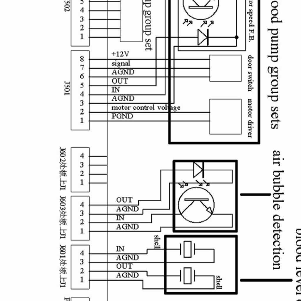
71
72
73 -73- Fig. 8-3
74 Fig
75 -75- Fig. 8-5
76 A B C D A B C Alam lamp LED/LCM module Array keyboard S R Q 1 0 Comm.port Power board part Alarm group set Main board Venous clomp set H.P. group set Na+ pump P Power supply part N M V.P.monitor Level adjust L TMP monitor A.P.monitor Air bubble Blood_level Spare pump Blood pump group sets group sets group sets group sets 4 F G H I J K Blood_leaked monitor Cond. monitor Temp. monitor Sampling part of water-way 2 3 Parallel Main board of port water-way U.F. pump Pump A Pump B E D C Wiring part Floater switch Hall switch Heating control Fan A B A B Power filter Elec_valve group Air_pump group Reclying pump Post-dialysis set G F E D C Fig. 8-6 Principle -76- sketch map
77 P24V PG EG 12V/7AH 12V/7AH ON/OFF 5VDC "OFF" signal on main board AC AC EG 220VAC EG 24VAC 220VAC 24VDC "OFF" signal T ON 90 C AC AC TEMP.SKIP SWITCH AC AC 220V/1200W Heating controlk signal JH075 EG JH072 NUMBER PART ANALOG PART POWER PART 4_G 0 N+5V NGND (Number Ground) A+12V A+5V A-5V A-12V AGND (Analog Ground) P+24V P+12V PGND (Power Ground) Fig. 8-7 Power supply -77- connection sketch map
78 N+3.3V SP3485 RS485 N+5V A B main board NG JH101 SN75176 Main board of water-way 1_A Fig. 8-8 Circuit of mainframe sketch map Recharging... Recharginge Over J207 1 Ext Power Using Battery J2 Number Part Battery Full 1 O Battery 2/3 Battery 1/3 JH-075 1_B JH-101 Battery Empty Fig. 8-9 Circuit of battery capacity feedback sketch map -78-
79 P+5V P+12V 330Hz J HMS 2.5'' U802 U801 X9C103S U803 LM386 PG JH101 1_C Fig Circuit of frequtncy control sketch map A+12V T702 U701 AD620 Zero1 AG T701 1mA W702 K W701 Zero2 AG 1_D Fig Circuit of venous pressure sensor sketch map -79-
80 A+12V T706 U703 AD620 Zero1 AG T701 1mA W708 K W707 Zero2 AG 1_F Fig Circuit of TMP sketch map A+12V T707 U705 AD620 Zero1 AG T705 1mA W705 K W704 Zero2 AG 1_G Fig Circuit of AP sketch map -80-
81 A+12V JH097 O202_3 Number Part T1=1mS T=64mS AG Sensitivity AG 1_H Fig Installation of air bubble inspection sketch map A+12V JH096 O202_1 Number Part T1=1mS T=64mS AG Sensitivity AG 1_I Fig Blood level inspection sketch map -81-
82 P+24V PG A+12V A+12V O501_1 AG Motor Driver M AG Number Part A+12V O201_4 Blood Pump Door Open/Close A3144E AG P+12V O204_1 Tubing switch PG Speed Control Signal (0-5V) Power Ground D/A Conver 1_J Fig Circuit of blood pump/spare pump control sketch map P+24V PG A+12V A+12V O501_2 AG Motor Driver M AG A+12V O201_3 Number Part Spare Pump Door Open/Close A3144E AG P+12V O204_2 Tubing switch PG Speed Control Signal (0-5V) D/A Conver Power Ground 1_K Fig Circuit of spare -82- pump control sketch map
83 P+12V O204_3 J408 Q402 PG O204_4 Q403 PG 1_L Fig Circuit of blood level adjustment control sketch map P+12V Step Motor Number Part U401 ULN2804 M Number Part O PG 1_M Level protection Fig Circuit of Na + pump control sketch map A+12V AG A3144E O201_2 P+12V A+12V A+12V O501_4 AG Number Part U401 ULN2804 M Step Motor AG Number Part O PG 1_N Level protection A+12V AG A3144E O201_1 Fig Circuit of heparin pump control sketch map -83-
84 P+12V P+12V O206-1 PG P+12V PG Number Part P+12V O206-2 PG PG JH101 1_N_A Fig Circuit of heparin pump pipe judgement sketch map A+12V J201 JH098 O206_3 Number AG Part NG A+12V P+24V J407 O406 Q401 PG 1_P Fig Circuit of venous line clamp sketch map -84-
85 N+3.3V TOUCH PANEL AGND J103 J104 JH101 1_Q Fig Circuit of touch screen control sketch map JH094 LIGHT J902 SOURCE CONVERT JP102 JH101 TFT PANEL 1_R Fig Circuit of display -85-control sketch map
86 P+12V J404 Part of Alarm lamp Number Part U401 ULN mA Red Green 5mA J405 O _S PG JH104 POWER "OFF" SIGNAL TO BACK-UP POWER BOARD Fig Circuit of alarm light control sketch map A+12V Detection cell A+12V OUT RBC>5*10exp9 20mA Light filter A+12V OUT>1000mV AG 2_A Fig Blood leakage inspection sketch map OSC Cond. cell Sync rectifying filter 0-20mS mV 1000Hz OUT AG A+12V AG A+12V K 2_B Fig Cond. inspection sketch map -86-
87 A3144 LM35 OUT ãc mV A+12V AG 2_C Number Part Fig Temperature detector sketch map JP501 P+12V 9 1 PG U503-1 Number Part D/A Conver JH065 3_A Fig Circuit of bobber switch feedback sketch map -87-
88 A3144 JP509 JP516 P+12V Number Part 3_B PG Fig Circuit of conector/door switch feedback sketch map P+12V P+24V P+24V Number Part 540 PG Step Motor M PG 3_C 3_D 3_E Fig Circuit of ratio pump control sketch map P+24V PG D/A Conver Speed Control Signal (0-5V) Power Ground Motor Driver M JH065 4_C 4_D Fig Circuit of blood pump rotation -88- speed control sketch map
89 P+12V P+24V P+24V Number Part 540 PG Electromagnetic Valve P+24V P+24V PG P+24V 4_E 4_F Air Pump Fig Circuit of electromagnetic valve control sketch map P+24V Set comparison Negative voltage generator 24V-+9V--6V 0-5V - + M+ PG Current FB. Voltage FB. M- PG Fig Circuit of motor control sketch map -89-


90 Fig JH101 MONDIAL 100 main board Fig Touch screen adapter board JH


91 Fig Power board JH075 Fig Core board JH


92 Fig Bubble detection board JH097 Fig Bubble sensor wiring connection board JH


93 Fig Standby power board JH068 Fig Conductivity detection board JH


94 Fig Waterway A/D transfer board JH063 Fig Waterway controlling main board JH


95 Fig Blood level detection board JH096 Fig Wiring connection board JH


96 Fig Alarm light board JH104 Fig Small display board JH


97 Fig DC motor speed adjusting board V2.0 JH044 Fig Voltage drive bood of blood pump JH044+JH

98 Fig Blood leakage detection board JH
99 9 Structural diagram of MONDIAL 100 Hemodialysis equipment parts 9.1 Outside view of MONDIAL 100 complete machine Front view -99-
100 Venous Venous line clamp Relieving Charging Start SBP DBP mmhg kpa Pulse ON/OFF Start Power P No. Name Picture No. Colour -100-
101 1 Above case Blue 2 Lampshade LCD LB104V03 4 Dialysis pump C White 5 Venious identifying patch Outer adapter Blood level adjusting switch Heparin pump D 9 Liquid clamp switch Cambridge blue 10 Air arresting clamp group C Cambridge blue 11 AB adapter group A Pink/ Cambridge blue 12 Adapter 6207B-0 13 Fluid infusion support B 14 Decorative panel Pipe-equip switch P1 identifying patch Dialyzer clamp Pulse pressure adapter 6218B-0C 19 Touch adapter Pink / Cambridge blue 20 Arterial pot stand Middle case Down-case of front panel Blue 23 Bottom case Blue 24 Base assembling diagram
102 9.1.2 Back view -102-
103 Dialyzer Dialyzer Supply Return 17 C44 C45 C Gas Vent Disinfector UF Sampling Valve 11 Drain Ro Water Connector
104 No. Name Picture No. Colour 1 Up-case in the back Blue 2 Box White 3 Fan KD2409PTB3 4 Data port seat (DP-9 needle) 5 Air switch + creepage protection accessory C65NC32 + VIGIC 6 Power connected port board Bottom-case in the back Blue 8 Pyrogen filter 9 Back case Blue 10 ventilation adapter dipartite cover 6207C Water inlet adaptor group Small decompression valve 5204A-0 13 Truckle 14 SpeakerΦ Fuse seat R3-44A 16 Air switch box Pyrogen filter collet Rolling lock A 19 Hexagonal nut M6 GB/T Aluminium adapter patch 21 Extermal teeth serrated flat washer M6 22 Blood leak inspector B -104-


105 9.2 Structural diagram of critical parts Pressure testing base ( ) Fig. 9-4 Fig. 9-5 NO. Name Quantity Model 1 Major body Pressure sensor 1 154/30P 3 Clamping ring Lid Pan head screws with cross M4x30 2 GB O-Ring GB One way valve(5202a-0a) Fig. 9-6 Fig. 9-7 NO. Name Quantity Model 1 One way valve body A-01A 2 Spring(9 type 0.413) Shim O-RingΦ12 Φ1.8 1 GB

106 5 One way valve lid A-05A Blood leakage inspector ( B) Fig. 9-8 Fig. 9-9 NO. Name Quantity Model 1 Front sealing lid Stressed top O-RING 1 GB/T Shim Back lid Chamber body B 7 Insulated gasket Self-tapping screw ST3X5 2 2 GB Blood leakage circuit board 1 JH Self-tapping screwst3.5x12 2 GB

107 9.2.4 Small electromagnetic valve(5102-0) Fig Fig Fig NO. Name Quantity Model 1 Water valve magnet spool S Joint sleeve B 3 Spring Φ A 4 Shim Moving iron core A 6 Screw nut M3 1 GB/T Clamping ring Septum perch C-02 9 Septum C Half moon

108 11 Salver Small valve body Balance chamber( j-0) Fig Fig NO. Name Quantity Model 1 Pan head screws with cross recess 8 GB/T M screw M4-M H-01B 3 O-Ring Φ8.5XΦ1.8 4 GB Pan head screws with cross recess 12 GB/T chamber body (two) F-04 6 balance chamber E valve A for small valve body 7 platen C-03 8 diaphragm 102* F-03 9 Diaphragm G impacted screw J cushion J pre-embed screw J O-Ring Φ14XΦ1.8 3 GB chamber body (one) J Flat gasket 4 32 GB Hexagonal Screw nut M4 12 GB/T adjustment bolt G hexagonal screw nut M4 1 GB/T
109 9.2.6 Gear pump(3102b-0) Fig Fig NO. Name Quantity Model 1 Pump base B 2 Shaft O-RING GB Driven magnetic loop Transitional tray A 6 H sunk screw with cross M3 8 3 GB Joint flange A-02 8 Sealing lid Flat gasket Spring gasket 4 6 GB
 3 GB/T823-1988 1 2 3 4 5 6 7 8 9 10 Fig.")
110 11 Small pan head screws with cross recess M Proportional pump (3203A-0B) 3 GB/T Fig Fig
111 NO. Name Quantity Model 1 Pan head screws with cross recess M Spring gasket 4 GB/T Elastic valve core A 3 Platen Water inlet adapter Water outlet adapter Elastic valve core B 7 O-Ring Pump lid Septum Lock sleeve A 11 Pump body Lock sleeve A 13 Spring Pressing sleeve Septum perch A 16 Clamping ring Spring Joint perch A 19 Stand Outer gasket Roll bearing 1 22 Inner gasket M5 hexagonal nut M5 1 GB/T Flat gasket-a-class 5 4 GB Eccentric cam sleeve Fluting flat-end set screw M4X Pump notched stick A 28 Stepper motor 1 57BYGH Pan head screws with cross recess M

 Fig. 9-22 Fig. 9-23 NO.")
112 Overflow valve (5205A-0) A 7 8 Fig Fig NO. Name Quantity Model 1 Adjustment screw Pan head screws with cross 4 sets GB/T recessm4 25 Spring gasket4 3 Valve lid A-03 4 Spring Φ Spring base Guide bar Septum adapter M 9 O-Ring GB Valve body A Hexagonal Screw nut M4 4 GB Bobber viewer ( ) Fig Fig NO. Name Quantity Model 1 Adapter M 2 O-Ring Φx1.8 1 GB

113 3 Bobber Viewing chamber M Blood pump(spare pump)(3103-0c) Fig Fig NO. Name Quantity Model 1 Motor B 2 Bolt 1 GB New upper flange or new blood pump lower flange BTS or TX 4 Pan head screws with cross recess M5X16 4 GB Spring gasket 5 4 GB Steel magnet 5X4 2 7 sunk screw with cross M3x6 4 GB Clamping tool Steel magnet 4X Pump hub rotor B 11 Pump lid Pump body Pin bolt of pump lid sunk screw with cross M4x12 4 GB Bearing pad Bearing GB/T Shield ring 32 1 GB Photoelectric switch 1 TP Spring gasket3 2 GB Pan head screws with cross recess M3x12 2 GB Tachometer disc Hall component 1 A44E -113-
114 -114-

115 Small pressure decreasing valve(5204a-0) Fig NO. Name Quantity Model 1 Adjustment screw Hexagonal Screw nut M10 2 GB Small pan head screws with cross recess 2 GB M5X30 4 Valve lid Flat gasket 5 4 GB Big Spring Spring socket Septum Top perch A O-RINGφ3.75Xφ1.8 1 GB Steel ball φ Valve body A Small Springφ5Xφ0.5Xφ O-RINGφ9Xφ1.8 1 GB Spring base O-RINGφ8Xφ1 1 Fig Flat gasket12 1 GB Adapter A Sunk screw with cross M5X12 2 GB/T Hexagonal Screw nut M5 2 GB Flat gasket 6 1 GB


116 Filter(6220-0E) Fig Fig NO. Name Quantity Model 1 Revolving lid Upper seat Filter screen B 4 Sealing glue Lower seat Heat exchanger( a-0) Fig Fig NO. Name Quantity Model 1 Hexagonal Screw nut M4 20 GB41-86 Hexagonal Screw nut M5 1 GB Heat exchanger body A-01A 3 Sealing ring Heat exchanging element A-02 5 Spring gasket 4 20 GB-/T93 Spring gasket 5 1 GB-/T93 6 Pan head screws with cross recess M GB

117 Pan head screws with cross recess M GB Pan head screws with cross recess M GB Air arresting clamp group (back)( b) Fig Fig Fig Fig Fig Fig NO. Name Quantity Model 1 Retaining plate Sunk screw with cross M GB/TB19 3 Flat gasket 4 2 GB Spring gasket 4 2 GB-/T93 5 Hexagonal Screw nut M4 2 GB Abutment Axis pin Joining block Driving block Circlip for shaft 4 2 GB Movable iron core
 10 测温头 9 11 8 12 13 7 1 2 3 4 5 6 Fig. 9-39 Fig. 9-40 NO.")
118 12 Gag post Blocking plate Electromagnet 1 4kg 24v 15 Electromagnetic valve Spring Supporting flange Axis pin Sunk screw with cross M GB/TB19 19 Spider Cross recessed round head screw M GB Conductivity( F -0C) 10 测温头 Fig Fig NO. Name Quantity Model 1 Main body cover F-01 2 O-type seal ring 6.3x1.8 6 GB O-type seal ring 18x1.8 1 GB Carbon Ring B-03B 5 Inner sleeve F-02D 6 Temperature-measuring cover F-04B 7 O-type seal ring 5.3x1.5 1 GB O-type seal ring 8x1 1 GB Temperature-measuring rotating cover F-03E 10 Bulk F-05B 11 Hexagon nut M4 6 GB/T Light spring hurdle washer 4 6 GB
119 13 Cross recessed small pan head screw M4x12 6 GB/T


120 Group AB adapter( ) Fig Fig Fig NO. Name Quantity Model 1 Silicone tubeφ6xφ Silicone tubeφ6xφ12x6 1 3 O-type seal ringφ4.8xφ2 2 GB Adapter O-type seal ringφ12.5xφ1.8 1 GB Cone-shaped adapter O-type seal ringφ9xφ1.8 2 GB Left and right seal Socket Cross recessed pan head tapping screw 4 GB M3.5X16 11 O-type seal ringφ33.5xφ1.8 1 GB SUPPORT Net-streak silica gel coverφ13xφ15x Tee PP-tube AB steel tube Bulkhead O-type seal ringφ6xφ1.8 1 GB Bulkhead adapter Hall component 1 A44E -120-

121 21 AlnicoΦ4X Rinse adapter(6205-0) Fig Fig NO. Name Quantity Model 1 Cross recessed countersunk head screw 3 GB M cross recessed countersunk head screw M3 7 1 GB Main adapter Spring Guide bush AlnicoΦ Sensing cover B 8 Board penetrator Cross recessed countersunk head screw 2 GB M Nut Hall component 1 AE

122 Air pump (3204-0C) part A 2:1 part A Fig Fig NO. Name Quantity Model 1 Electric engine jacket Electric engine 29SYT Body case Ball sleeve B 5 Seal plate Chaff jacket Septum Septum cavity Valve A 10 Coming in and going out Pressure plate Hexagon socket set screws with flat point 1 GB77-85 M3X4 13 Eccentric wheel Bearing cover B 15 Pre-set nut Model 6000,series 37, 8x12x3.5 mini-type 1 GB/T

123 Technical manual of ALICE hemodialysis unit Heater( H-0E) 向 Fig 向 Fig NO. Name Quantity Model 1 Adapter M 2 O-type seal ringφ3.15*φ GB Cavity H-04E 4 O-type seal ringφ28*φ1.8 4 GB Small bulk H-07 6 Small bulk H-06 7 Press lid H-05B 8 Big bulk H-01 9 O-type seal ringφ63*φ1.8 3 GB Big bulk H Liquid-level switch 1 FASF-42LP-1A1 12 Hexagon nut M10 4 GB-T Sealed spacer 4 14 Non-return washer H-11B 15 Catch (φ61) H Catch (φ29) H Thin plate H Press cover H Cross recessed countersunk head screw M4*12 4 GB/TB


124 Technical manual of ALICE hemodialysis unit 20 O-type seal ringφ8.55*φ1.8 2 GB Heparin pump(3201-0b) 1 Fig Fig Fig Fig NO. Name Quantity Model 1 Pedestal Vertical battens board B 3 Support Dia-testing photoelectricity pedestal Stepper motor/37jb-42by 1 6 Cross recessed small pan head screw 2 GB/T M4X10 7 Adjusting screw B 8 Hall component adjusting clamp Dia-testing photoelectricity pedestal Component parts of pressure head Jacket Lead screw
125 Technical manual of ALICE hemodialysis unit 2 13 Lid Slotted set screws with cone point M3 4 2 GB Lead screw gear Vertical battens board B Fig Fig NO. Name Quantity Model 1 Adjusting screw B 2 Hall component pedestal Locknut Hall component adjusting clamp φ1 steel wire approximates 20mm 2 GB/T Nut M5 1 GB/T Cross recessed small pan head screw 2 GB95-85 M4X12 8 Plain washer 2 GB Pedestal Needle cylinder clamp Dia-testing rod B 12 Circlip Φ2mm steel wire approximates 16mm 1 14 Spring washer 4 2 GB Spring
126 Technical manual of ALICE hemodialysis unit 3 Fig NO. Name Quantity Model 1 Electric engine gear Big wheel spindle Circlips for shaftφ5 1 GB Transmission gear Lead screw gear Slotted set screws with cone point M3X4 2 GB Bottom sheath Spring collet (20ml,30ml,50ml) Knob Press head group Washer 1, washer 2 1 for each and

127 Technical manual of ALICE hemodialysis unit Dialyzer clamp (6303D-0) Fig Fig NO. Name Quantity Model 1 joint lever rolling lock connecting rod dialyzer clamp slotted set screws with cone point M GB tube clamp spindle steel slab A-02B 9 swivel gantry B 10 spring Elastic block dialyzer collet A -127-
128 Technical manual of ALICE hemodialysis unit 9.3 Other spare parts -128-

 Fig.")
 Nut (")
 Fig.")

")
 Adapter end cap Fig.")
 Pressure plate (")
 Fig.")
 -129- Fig.")
129 Technical manual of ALICE hemodialysis unit Fig Transition adapter (6222) ( For water-supply septum pump ) Fig Small tee ( 6213 ) Fig Nut B ( 6207B-02 ) Nut ( ) Adapter B ( 6207B- 01 ) Adapter ( ) Fig Crutch pole ( ) Fig Rapid adapter sleevetype B ( ) Fig Bonding comer bracket ( 6231 ) Bonding tee bracket ( 6230 ) Tube clamp ( 6302 ) Adapter end cap Fig Pressure plate ( C-03 ) ( left ) Pressure plate ( ) ( right ) Fig Fan ( ) Fig Sphygmomanometer group ( ) Fig Pulse pressure adapter ( 6218B-0C ) Extermal teeth serrated lock washer 10 ( GB862.2 ) Hexagon nut M10 ( GB41 )


 Hexagon nut M12 (")


130 Technical manual of ALICE hemodialysis unit Fig Inlet adapter ( ) Internal teeth serrated lock washer 12 ( GB861.2 ) Hexagon nut M12 ( GB41 ) Fig Thin dia adapter ( 6233 ) Fig Battery case ( ) Fig accumulator ( ) Fig Solid relay ( ) Fig Lipuid crystal group ( Y-0 ) Fig BPM Membrane ( ) Fig LCD ( )


 Fig.")
 Fig.")
 Fig.")
 Fig.")
 Fig.")
 Fig.")
131 Technical manual of ALICE hemodialysis unit Fig Positive pressure pump ( ) Fig Negative pressure pump ( ) Fig Identifying patch Fig Filter ( ) Fig Photoelectricity swith ( ) Fig Air valve ( ) Fig Altrasonic inspector seat ( ) Fig High temperature safety switch 90 ( ) Fig Fuse holder ( ) Fig Venous line clamp door ( ) Fig Truckle ( ) Fig Transformer ( )

 Fig. 9-85 AC filter ( 1.47.")
 Fig.")
 Fig.")
 Fig.")
 Fig.")
 Φ6Х12 ( 2.28.0004 ) Fig.")
 Top holding prdesta (")
132 Technical manual of ALICE hemodialysis unit Fig Key-press platelet ( ) Fig AC filter ( ) Fig Alarm sprake ( ) Fig Hengfu switching power supplly ( ) Fig Waterproof adapter ( ) Fig Connecting terminal ( ) Fig Silicone tube Φ4Х8 ( ) Φ6Х12 ( ) Fig Bottom holding prdestal ( ) Top holding prdesta ( ) Fig LCD connecting line ( ) Fig Rotation pin ( B ) Fig Blood level adjusting switch ( )
Contacts. Quick Start Guide
 Contacts Clinical Support Specialist: Phone: Cell Phone: Email: Fresenius Renal Technologies A division of Fresenius Medical Care North America 920 Winter Street Waltham, MA 02451 Technical Service Customer
MANITOBA RENAL PROGRAM
 MANITOBA RENAL PROGRAM SUBJECT Fresenius 5008 Preparation for Hemodialysis using the ONLINEplus System SECTION CODE 30.10.02 30.10 Hemodialysis: Equipment and Procedures AUTHORIZATION Professional Advisory
- Repeat calibration until desired results are reached otherwise set SW2 and SW1-8 open.
 Calibration Procedures on Cobe Centrysystem 3: I) Balance Chamber Calibration: - Verify that pressure regulators PRV and PRV2 are calibrated as well as pressure transducers PDI and PDO with switches SW2
CRRT with Prismaflex LEADS TO More Flexibility, Ease of Use and Safety
 CRRT with Prismaflex LEADS TO More Flexibility, Ease of Use and Safety Leading the way Science is changing and so are your requirements For many years, Gambro has focused its efforts on development of
AQUARIUS Continuous Renal Replacement Therapy Competency
 Preparation Explain the procedure to the patient and significant others Prepare the patient. Prepare the environment. Ensure a safe environment for the patient and staff Gather equipment required to Setup
Indications for Use: Caution: Note:
 IV 1 2 IV This reference is to be used in conjunction with the Crit-Line IV Monitor User s Guide (P/N CL80050002). Refer to the User s Guide for a complete description of alerts, warnings, cautions, and
CCT-7320/ROC-2313 Reverse Osmosis Controller
 CCT-7320/ROC-2313 Reverse Osmosis Controller 1 General The instrument is a combined control instrument of a reverse osmosis controller and an on-line conductivity instrument. It can perform the operation
Armfield Distillation Column Operation Guidelines
 Armfield Distillation Column Operation Guidelines 11-2016 R.Cox Safety SAFETY GLASSES ARE REQUIRED WHEN OPERATING THE DISTILLATION COLUMN Wear gloves when mixing alcohol feedstock The column will become
Pegas 4000 MF Gas Mixer InstructionManual Columbus Instruments
 Pegas 4000 MF Gas Mixer InstructionManual Contents I Table of Contents Foreword Part I Introduction 1 2 1 System overview... 2 2 Specifications... 3 Part II Installation 4 1 Rear panel connections...
Quiz for Module 2: Aquarius Training (Rev. 1) Lesson 1: Introduction to Aquarius
 Lesson 1: Introduction to Aquarius") Quiz for Module 2: Aquarius Training (Rev. 1) Lesson 1: Introduction to Aquarius page 1 of 2 Name: Date: Score: Instructor: Location: Please circle the correct answers: 1. Select the answer(s) that represent
Quiz for Module 2: Aquarius Training (Rev. 1) Lesson 1: Introduction to Aquarius page 1 of 2 Name: Date: Score: Instructor: Location: Please circle the correct answers: 1. Select the answer(s) that represent
INSTRUCTION MANUAL. Automatic Water Softener System. Model: PSE-08. Xsential Water Filtration Systems
 INSTRUCTION MANUAL Automatic Water Softener System Model: PSE-08 Xsential Water Filtration Systems 78 Daly Street Ascot Western Australia 6104 Ph: 1300 366 295 Fax: (08) 9277 2266 www.xsential.com.au Welcome
Troubleshooting Guide Aquarius
 Low Access Pressure Access pressure has dropped below the lower alarm limit of 0 to - 250mmHg Blood pump is off Blood flow is too low Turn blood pump on Check blood flow rate. Consider increasing the blood
Cover Page for Lab Report Group Portion. Head Losses in Pipes
 Cover Page for Lab Report Group Portion Head Losses in Pipes Prepared by Professor J. M. Cimbala, Penn State University Latest revision: 02 February 2012 Name 1: Name 2: Name 3: [Name 4: ] Date: Section
AQUADEX FLEXFLOW SYSTEM QUICK REFERENCE GUIDE
 AQUADEX FLEXFLOW SYSTEM QUICK REFERENCE GUIDE AQUADEX FLEXFLOW SYSTEM DISCLAIMER The quick reference guide is not intended to replace CHF Solutions, Inc. Aquadex FlexFlow Direction For Use (DFU). Always
Manual of SF6 Comprehensive Tester
 Manual of SF6 Comprehensive Tester Important Description All the staff taking in charge of the usage or maintenance of this product should carefully read this manual. The same as any other complicated
UsER manual for Watersens ph -REDOX
 UsER manual for Watersens -REDOX Cl 8 1 2 6 3 3 7 7 4 4 4 4 Parts List 1 Redox Probe 1 x 2 PH Probe 1 x 5 Tube Weight 2 x 6 Connection Valve 1 x chlorine 3 Chlorine and Pumps 2 x 7 Dosing Valve 2 x 5 5
ACV-10 Automatic Control Valve
 ACV-10 Automatic Control Valve Installation, Operation & Maintenance General: The Archer Instruments ACV-10 is a precision automatic feed rate control valve for use in vacuum systems feeding Chlorine,
Module 2: Aquarius Training
 Module 2: Aquarius Training Module 2: Aquarius Training 1 AQUARIUS TRAINING TABLE OF CONTENTS Lesson 1. Introduction to Aquarius Platinum Lesson 2. Preparing Aquarius Lesson 3. Treatment Mode Lesson 4.
SomnoSuite FAQ. Setup. Calibration 4. What are the calibration requirements for the SomnoSuite? Settings
 SomnoSuite FAQ V1.3 January 2015 Setup 1. How do I connect the SomnoSuite to my oxygen source? 2. Is there a way to speed up the downward movement of the pusher block when setting the empty position? 3.
Columbus Instruments
 0215-003M Portable O 2 /CO 2 /CH 4 Meter User s Manual Columbus Instruments 950 NORTH HAGUE AVENUE TEL:(614) 276-0861 COLUMBUS, OHIO 43204, USA FAX:(614) 276-0529 1 www.colinst.com TOLL FREE 1-800-669-5011
1020 Industrial Drive, Orlinda, TN fax
 Operation Manual Tank Distribution System A-UPT Series 615-654-4441 sales@specialtyh2o.com 615-654-4449 fax TABLE OF CONTENTS Section 1 GENERAL 1.2 Warnings and Cautions... 1 1.2 Theory of Operation...
Instructions for Use
 Select-380 T-Auto T-Auto Contents Page Instructions for Use Ref: 3.0 IFU 380 T-Auto Mar 18 2 Schematic layout of the doser 3 Quick-fit instructions 4 Description/Installation/Operation Pump tubes & Water
AQUARIUS Continuous Renal Replacement Therapy with Regional Citrate Anticoagulation (RCA) Competency
 Competency") Demonstrates an understanding of why RCA has been prescribed Explain the anticoagulation protocol Demonstrate an understanding of potential complications associated with CRRT. Explain potential indications
Demonstrates an understanding of why RCA has been prescribed Explain the anticoagulation protocol Demonstrate an understanding of potential complications associated with CRRT. Explain potential indications
BUBBLER CONTROL SYSTEM
 BUBBLER CONTROL SYSTEM Description: The HDBCS is a fully automatic bubbler system, which does liquid level measurements in water and wastewater applications. It is a dual air compressor system with, air
HAEMOFILTRATION GUIDELINES
 HAEMOFILTRATION GUIDELINES The treatment mode used for Continuous Renal Replacement Therapy on the Cardiff PICU is Continuous Veno-Venous Haemofiltration (CVVH). CVVH facilitates the continuous Convective
Exercise 5-2. Bubblers EXERCISE OBJECTIVE DISCUSSION OUTLINE. Bubblers DISCUSSION. Learn to measure the level in a vessel using a bubbler.
 Exercise 5-2 Bubblers EXERCISE OBJECTIVE Learn to measure the level in a vessel using a bubbler. DISCUSSION OUTLINE The Discussion of this exercise covers the following points: Bubblers How to measure
Stand-Alone Bubble Detection System
 Instruction Sheet P/N Stand-Alone Bubble Detection System 1. Introduction The Bubble Detection system is designed to detect air-bubble induced gaps in a bead of material as it is being dispensed. When
AKTA pure 25 New Owner s Intro
 AKTA pure 25 New Owner s Intro The exercise below will give a quick demonstration of how easy and intuitive the AKTA pure 25 will be for you in demonstrating downstream processing to your students. Steps
The Univentor 1250 Anaesthesia Unit
 THE UNIVENTOR 1200/1250 ANAESTHESIA UNIT The Univentor 1250 Anaesthesia Unit TABLE OF CONTENTS EDITION 1 Section 1 - WARRANTY & SERVICE 1.1. WARRANTY 2 1.2. DAMAGED SHIPMENTS 2 1.3. SERVICE 2 Section 2
Blue River Technologies Port-A-Poly Mixer w/2.5 GPH LMI Pump And Secondary Water Dilution Line INSTALLATION AND OPERATION
 Blue River Technologies Port-A-Poly Mixer w/2.5 GPH LMI Pump And Secondary Water Dilution Line INSTALLATION AND OPERATION Install your Blue River Technologies Port-A-Poly mixing system in a clean dry area.
Hemoglobin Reference Failure Troubleshooting
 Hemoglobin Reference Failure Troubleshooting The HEMOGLOBIN REFERENCE FAILURE error ( HGB REF FAILURE ) is generated by the Vet ABC as a quality control check for hemoglobin measurement. Recall that the
AHE58/59 AC Servo System
 AHE58/59 AC Servo System HMI-12 User Manual Safely INstruction Please read this manual carefully, also with related manual for the machine head before use. For perfect operation and safety, installing
RD(H)20/25 Pressure-Reducing Regulator User Manual
20/25 Pressure-Reducing Regulator User Manual") RD(H)20/25 Pressure-Reducing Regulator User Manual Read the complete manual before installing and using the regulator. 2 Safe Product Selection When selecting a product, the total system design must be
RD(H)20/25 Pressure-Reducing Regulator User Manual Read the complete manual before installing and using the regulator. 2 Safe Product Selection When selecting a product, the total system design must be
1020 Industrial Drive, Orlinda, TN fax
 Operation Manual Ultrafiltration for High Purity Distribution K-A-HPTUF Series 615-654-4441 sales@specialtyh2o.com 615-654-4449 fax TABLE OF CONTENTS Section 1 GENERAL 1.1 Warnings and Cautions... 1 1.2
DRS4-RM Manual. Set Up Instructions for DRS4 Series Single Tank
 Set Up Instructions for DRS4 Series Single Tank Inspect the packaging of the equipment to confirm that nothing was damaged during shipping. (Figure 1) Remove the resin tank(s) and valve(s) from the packaging.
Roller AC Servo System
 Safely Instruction Roller AC Servo System HMI-15 User Manual Please read this manual carefully, also with related manual for the machinery before use the controller. For installing and operating the controller
Endo-Flush Order # ZUTR30004 OPERATION MANUAL. Zutron Medical, LLC W 98 th St #40-27 Lenexa, KS Phone Fax
 OPERATION MANUAL Zutron Medical, LLC 17501 W 98 th St #40-27 Lenexa, KS 66219 Phone 877-343-5873 Fax 913-967-5944 ZUT-Lab-004-30004 REV. 03312017 Table of Contents 2 Introduction 1. Intended Use 2. Labels,
LRS(H)4 Pressure-Reducing Regulator User Manual
4 Pressure-Reducing Regulator User Manual") LRS(H)4 Pressure-Reducing Regulator User Manual Read the complete manual before installing and using the regulator. 2 Safe Product Selection When selecting a product, the total system design must be considered
LRS(H)4 Pressure-Reducing Regulator User Manual Read the complete manual before installing and using the regulator. 2 Safe Product Selection When selecting a product, the total system design must be considered
PROPORTIONING VALVE. Model 150 INSTRUCTION MANUAL. March 2017 IMS Company Stafford Road
 PROPORTIONING VALVE Model 150 INSTRUCTION MANUAL March 2017 IMS Company 10373 Stafford Road Telephone: (440) 543-1615 Fax: (440) 543-1069 Email: sales@imscompany.com 1 Introduction IMS Company reserves
patient education program 4156 South 52 nd Street, Omaha, NE ChildrensOmaha.org/HomeHealthcare
 patient education program 4156 South 52 nd Street, Omaha, NE 68117 800-747-7334 402-734-6741 ChildrensOmaha.org/HomeHealthcare We know children CHILDREN S HOME HEALTHCARE Trilogy Ventilator Instructions
Instructions for Assembly, Installation, and Operation of the Gas Addition Kit Accessory with the CEM Discover Systems
 Corporation Issued: 5/09 P/N: 600104 Rev. 2 Instructions for Assembly, Installation, and Operation of the Gas Addition Kit Accessory with the CEM Discover Systems The Gas Addition Accessory permits the
with O 2 Controller Instruction Manual
 14500 Coy Drive, Grass Lake, Michigan 49240 734-475-2200 E-mail: sales@coylab.com www.coylab.com Hypoxic Cabinets (In-Vivo / In-Vitro) with O 2 Controller Instruction Manual Index Page Warranty 2 Warnings
MANITOBA RENAL PROGRAM
 MANITOBA RENAL PROGRAM SUBJECT Fresenius AquaUNO Reverse Osmosis System; use of SECTION CODE 30.30.04 30.30 Water Treatment AUTHORIZATION Professional Advisory Committee, Manitoba Renal Program Nursing
TANK MANAGER FOR TWO TANKS OPERATING MANUAL. 10/31/11 C-More T6C L color touch panel
 TANK MANAGER FOR TWO TANKS OPERATING MANUAL 10/31/11 C-More T6C L color touch panel 1 TABLE OF CONTENTS GENERAL...3 INSTALLATION...4 STONE TEST PROCEDURE...7 OPERATIONAL SUMMARY...7 AUTO CARBONATION...10
A4 Operation Manual. Fig.1-1 Controller Socket Diagram
 A4 Operation Manual Safety Instruction Please read this manual carefully, also with related manual for the machinery before use the controller. For installing and operating the controller properly and
RS(H)10,15 USER MANUAL. Read the complete manual before installing and using the regulator.
10,15 USER MANUAL. Read the complete manual before installing and using the regulator.") RS(H)10,15 USER MANUAL Read the complete manual before installing and using the regulator. WARNING INCORRECT OR IMPROPER USE OF THIS PRODUCT CAN CAUSE SERIOUS PERSONAL INJURY AND PROPERTY DAMAGE. Due to
RS(H)10,15 USER MANUAL Read the complete manual before installing and using the regulator. WARNING INCORRECT OR IMPROPER USE OF THIS PRODUCT CAN CAUSE SERIOUS PERSONAL INJURY AND PROPERTY DAMAGE. Due to
FAULT CODE TROUBLESHOOTING INDEX
 FAULT CODE TROUBLESHOOTING INDEX 1. Display indicates Change Filters 2. Display indicates Drip Tray Full Continuous Alarm will Sound 3. Display indicates Cold Fault 4. Display indicates Hot Fault 5. Display
Easy Nest Kits. Installation Suggestions
 Easy Nest Kits Installation Suggestions 2 General Recommendations Hydraulics Vacuum breakers should be installed to prevent siphoning. Flexible connectors should follow FRP tank manufacturers recommendations.
OPERATION MANUAL RTI RHS650 RTI TECHNOLOGIES, INC East Market Street York, PA Manual P/N
 OPERATION MANUAL RTI RHS650 RTI TECHNOLOGIES, INC. 4075 East Market Street York, PA 17402 Manual P/N 035-80589-02 Table of Contents Components... 2 Test... 4 Recovery/Recycling... 5 Evacuation... 7 Charging...
User Manual for the Mars Calibration Bench
 User Manual for the Mars Calibration Bench Fall 2013 Table of Contents Table of Contents Table of Contents... iii Introduction... v Chapter 1: The Mars Calibration Bench... 1 What Is the Mars Calibration
Installation of Your SprayMaster System
 Installation of Your SprayMaster System 1. At the installation site, remove all equipment from the corrugated box and the polyethylene drum and replace the drum lid. Check the picture to identify each
CDS-2000 CO 2 Sensor Verification, Calibration, and Troubleshooting Bulletin
 Electronic Control Manual 216 Sensors and Stats Section S Technical Bulletin CDS-2000 Issue Date 0393 CDS-2000 CO 2 Sensor Verification, Calibration, and Troubleshooting Bulletin Introduction 3 Pre-Verification
A4s Operation Manual
 A4s Operation Manual Safety Instruction Please read this manual carefully, also with related manual for the machinery before use the controller. For installing and operating the controller properly and
WATER TREATMENT SYSTEM OPERATION MANUAL
 WATER TREATMENT SYSTEM OPERATION MANUAL SYSTEM COMPONENTS A demonstration video of the system is available on our YouTube channel. You can view it by clicking on the following link. youtube.com/watch?v=mwlcfeliuzc
Overview. Front Panel: Keypad and Display
 Overview The GA-200B is an analyzer that integrates a gas sampling system with sensors to measure and display the concentrations of oxygen and carbon dioxide in a sample as the percentage of a gas in the
KIV-SACS Safe automatic calibration system:
 KIV-SACS Safe automatic calibration system: LOK: g:\prosjekter\calibration_system\kiv safe calibration system.doc Page: 1 of 14 Parts description:... 4 Wash extractors:... 6 Tunnel washers:... 5 Test valve:...
AQUARIUS. Operating Instructions for the. Type 70 Electrolytic Gas Soldering / Welding Unit. Table of Contents
 AQUARIUS Operating Instructions for the Type 70 Electrolytic Gas Soldering / Welding Unit Table of Contents 1. Important General Remarks 2 2. Safety Instructions 2 3. Description of the Soldering Unit
36E DSI, HSI & Proven Pilot Two-Stage Combination Gas Valve INSTALLATION INSTRUCTIONS
 INLET PRESS TAP WTE-RODGERS 36E96-314 DSI, HSI & Proven Pilot Two-Stage Combination Gas Valve INSTALLATION INSTRUCTIONS Operator: Save these instructions for future use! FAILURE TO READ AND FOLLOW ALL
Multiple Pressure Booster Systems With Variable Speed Controller Type BL
 Multiple Pressure Booster Systems With Variable Speed Controller Type BL General Characteristics - Single or multistage pumps - Horizontal or vertical mounting - Total head 30m ~ 250m - Material construction:
OWNER S TECHNICAL MANUAL
 EL SERIES OWNER S TECHNICAL MANUAL DP7002 1 Air Operated Diaphragm Pump Description The DP7002 1 air operated diaphragm pump is the ideal device for the pumping, transfer and dispensing of chemical liquids,
TR Electronic Pressure Regulator. User s Manual
 TR Electronic Pressure Regulator Page 2 of 13 Table of Contents Warnings, Cautions & Notices... 3 Factory Default Setting... 4 Quick Start Procedure... 5 Configuration Tab... 8 Setup Tab... 9 Internal
SAPCON. User Manual. Capacitance Continuous Level Indicator. . Introduction. . General Description. . Principle of Operation. .
 User Manual Capacitance Continuous Level Indicator Comprehensive User s Manual. Introduction. General Description. Principle of Operation. Specifications. Connection Diagrams. Quick Calibration Chart.
UNITY 2 TM. Air Server Series 2 Operators Manual. Version 1.0. February 2008
 UNITY 2 TM Air Server Series 2 Operators Manual Version 1.0 February 2008 1. Introduction to the Air Server Accessory for UNITY 2...2 1.1. Summary of Operation...2 2. Developing a UNITY 2-Air Server method
O2100C Oxygen Measurement Module Technical Use Notes do not use other wall adapters with the O2100Cmodule. 10% / V 5% / V 2% / V 1% / V 10% / V
 O2100C Oxygen Measurement Module The O2100C module measures the partial pressure of O2 and thus the module output is proportional to the pressure in the sample cell. Gas sampled must be free of liquids
USER MANUAL OPERATION AND THE USE OF A CAR WITH. Diego G3 / NEVO SEQUENTIAL GAS INJECTION SYSTEM
 USER MANUAL OPERATION AND THE USE OF A CAR WITH Diego G3 / NEVO SEQUENTIAL GAS INJECTION SYSTEM Page 2 / 8 Table of csontents 1. STARTING THE ENGINE... 3 2. CONTROL PANEL... 3 2.1 Indication of the current
SPECIFICATIONS APCEPH1
 APCEPH1 ph CONTROLLER SPECIFICATIONS APCEPH1 Input voltage 120 Volts AC Maximum amperage 14.5 amps @ 120 VAC ph Accuracy +/- 0.2 ph ph Control range Adjustable 4.5 8.5 ph Weight < 1 lbs Dimensions 3" x
Table of contents. Table of contents 1. Installation 2. Introduction ( Display, monitor ) 3. Introduction ( Operating elements ) 4
 3. Introduction ( Operating elements ) 4") Table of contents page 1 CONTENTS PAGE Table of contents 1 Installation 2 Introduction ( Display, monitor ) 3 Introduction ( Operating elements ) 4 Introduction ( Result interpretation) 5 Factory default
Table of contents page 1 CONTENTS PAGE Table of contents 1 Installation 2 Introduction ( Display, monitor ) 3 Introduction ( Operating elements ) 4 Introduction ( Result interpretation) 5 Factory default
SOFTENER D-DF & D-UF Series
 Water conditioning System. SOFTENER D-DF & D-UF Series INSTRUCTION MANUAL, OPERATION & MAINTENANCE 1. - PRESENTATION. In this manual, what is described are the required actions for the instalment, start
Flamco Flamco-Fill STA Flamco-Fill STM
 STA STM Typ STA 5936 Typ STM 5937 GB Installation and operating instructions 1999, 2 Contents GB UK Limited P.O. Box 9, Washway Lane, St. Helens, Merseyside WA10 6FE United Kingdom Telephone: 01744 744744
Automatic Isokinetic Sampler. ST5 Evo
 Automatic Isokinetic Sampler ST5 Evo Automatic Isokinetic Sampler ST5 Evo Moreover, in case of pump failure, the CU can work with a spare Dado PU unit or with any pump capable to supply the needed flowrate,
ECONORESS ELECTRONIC EPS & EPT - ENHANCED PRESSURISATION SET INSTALLATION OPERATION & MAINTENANCE DOCUMENTATION
 ECONORESS ELECTRONIC EPS & EPT - ENHANCED PRESSURISATION SET INSTALLATION OPERATION & MAINTENANCE DOCUMENTATION OCT2010 STOKVIS ENERGY SYSTEMS 96R WALTON ROAD EAST MOLESEY SURREY KT8 0DL TEL: 020 87833050
SG36KTL-M Quick Installation Guide. 1 Unpacking and Inspection
 SG36KTL-M Quick Installation Guide This guide provides a general instruction of the installation procedures of SG36KTL-M. In no case shall this guide substitute for the user manual or related notes on
I T T Pressure Reducing Valve WARNING INSTALLATION, OPERATION, AND MAINTENANCE MANUAL
 INSTALLATION, OPERATION, AND MAINTENANCE MANUAL I-867-4T 867-4T Pressure Reducing Valve HANG THESE INSTRUCTIONS ON THE INSTALLED VALVE FOR FUTURE REFERENCE WARNING Read and understand all instructions
300 Held Drive Northampton Pa
 300 Held Drive Northampton Pa 18067 610.262.6090 June 10, 2015 Recommended testing for verifying device performance. Intervals of testing are to be set by the Healthcare Provider / Dealer. Table of Contents
Cover Page for Lab Report Group Portion. Pump Performance
 Cover Page for Lab Report Group Portion Pump Performance Prepared by Professor J. M. Cimbala, Penn State University Latest revision: 02 March 2012 Name 1: Name 2: Name 3: [Name 4: ] Date: Section number:
BUBBLER CONTROL SYSTEM
 BUBBLER CONTROL SYSTEM Description: The LDBCS is a fully automatic bubbler system, which does liquid level measurements in water and wastewater applications. It is a dual air compressor system with, air
PRC CO ² -LASER PRESENTATION
 Page 1 of 7 PRC CO ² -LASER PRESENTATION GENERAL CHARACTERISTICS - Embedded PC104 Electronics with exchangeable software allowing very easy integration of customer specified functions: such as eg. specific
Reverse Osmosis System Installation Guide and Operation Manual.
 Reverse Osmosis System Installation Guide and Operation Manual. Table of Contents 1 Introduction...2 2 Installation...3 2.1 Feed water connection...3 2.2 Permeate and concentrate plumbing...3 2.3 Electrical
Agilent ICP-MS Interactive Troubleshooting tool for Low sensitivity
 Agilent ICP-MS Interactive Troubleshooting tool for Low sensitivity Rev. B 2017,Janyary,20 Next > Preconditions 7900, 7800, 7700, or 8800 ICP-MS is used. Sample introduction type is PeriPump. If you are
PRS(TC)4,8 USER MANUAL. Read the complete manual before installing and using the regulator.
4,8 USER MANUAL. Read the complete manual before installing and using the regulator.") PRS(TC)4,8 USER MANUAL Read the complete manual before installing and using the regulator. WARNING INCORRECT OR IMPROPER USE OF THIS PRODUCT CAN CAUSE SERIOUS PERSONAL INJURY AND PROPERTY DAMAGE. Due to
PRS(TC)4,8 USER MANUAL Read the complete manual before installing and using the regulator. WARNING INCORRECT OR IMPROPER USE OF THIS PRODUCT CAN CAUSE SERIOUS PERSONAL INJURY AND PROPERTY DAMAGE. Due to
ZIRCONIA OXYGEN DETECTOR SERVICE MANUAL
 Service Manual ZIRCONIA OXYGEN DETECTOR SERVICE MANUAL TYPE: ZFK 3, 4, 7 TN5A08a-E CONTENTS. PREFACE.... MEASUREMENT PRINCIPLE... 3. ADJUSTMENT...3 3. Zero (Air) Adjustment... 3 3. Span Adjustment... 3
THE UNIVENTOR 400 ANAESTHESIA UNIT
 THE UNIVENTOR 400 ANAESTHESIA UNIT TABLE OF CONTENTS EDITION 3 Section 1 - WARRANTY & SERVICE 1.1. WARRANTY 2 1.2. DAMAGED SHIPMENTS 2 1.3. SERVICE 2 Section 2 - INTRODUCTION 2.1. INTRODUCTION 3 Section
Calibration Gas Instrument INSTRUCTION MANUAL. Release I. Advanced Calibration Designs, Inc.
 Advanced Calibration Designs, Inc. Calibration Gas Instrument INSTRUCTION MANUAL Release I www.goacd.com Instruction Manual Gas Generator Release I TABLE OF CONTENTS I. General Description Page 2 II. Start-Up
Equipment Operating Procedure Glove Box
 Equipment Operating Procedure Glove Box Page 1 0.0 Changing the Compressed Gas Cylinder 1. Complete Compressed Gas Cylinder training from EHS website before manually exchanging gas cylinders. In order
Liberty Cycler Handi-Guide
 Liberty Cycler Handi-Guide A Patient s Reference to the Most Commonly Asked Questions about the Liberty Cycler This information is not intended to replace the advice or training from your physician or
RHPS Series RD(H)F40 User Manual. Read the complete manual before installing and using the regulator.
F40 User Manual. Read the complete manual before installing and using the regulator.") RHPS Series RD(H)F40 User Manual Read the complete manual before installing and using the regulator. 2 WARNING Before removing a regulator from the system for service, you must depressurize system purge
RHPS Series RD(H)F40 User Manual Read the complete manual before installing and using the regulator. 2 WARNING Before removing a regulator from the system for service, you must depressurize system purge
36E03 and 36E38 DSI and HSI Step Opening Combination Gas Valve INSTALLATION INSTRUCTIONS
 INLET PRESS TAP WHITE-RODGERS 36E03 and 36E38 DSI and HSI Step Opening Combination Gas Valve INSTALLATION INSTRUCTIONS Operator: Save these instructions for future use! FAILURE TO READ AND FOLLOW ALL INSTRUCTIONS
VACUUM REGULATORS CONTENTS
 CAD drawing data catalog is available. ACCESSORIES GENERAL CATALOG AIR TREATMENT, AUXILIARY, VACUUM, AND FLUORORESIN PRODUCTS CONTENTS Small Regulators Features 759 Specifications, Order Codes, Flow Rate
PERFORM Operating Document
 PERFORM Operating Document Use and Maintenance of CO 2 Incubator PC-POD-CA-007-v02 Revision History Version Reason for Revision Date 01 New POD 30-Sep-13 02 Minor revisions for section 2.3, 3.1, 4.3. 14-April-16
GM Series Dual-Block Multi-Function Gas Control Valves
 Installation Sheets Manual 121 Gas Combustion Combination Controls and Systems Section G Technical Bulletin GM Issue Date 0297 GM Series Dual-Block Multi-Function Gas Control Valves Figure 1: GM Series
JETFIRST 150 RTA SYSTEM OPERATING MANUAL Version: 2 Feb 2012
 JETFIRST 150 RTA SYSTEM OPERATING MANUAL Version: 2 Feb 2012 UNIVERSITY OF TEXAS AT ARLINGTON Nanofabrication Research and Teaching Facility TABLE OF CONTENTS 1. Introduction....2 1.1 Scope of Work.....2
Bante821 Portable Dissolved Oxygen Meter Instruction Manual
 Bante821 Portable Dissolved Oxygen Meter Instruction Manual BANTE INSTRUMENTS CO., LTD Bante821 Portable Dissolved Oxygen Meter 1 Introduction Thank you for selecting the Bante821 portable dissolved oxygen
In Vivo Scientific, LLC INSTRUCTION MANUAL
 CO 2 Controller In Vivo Scientific, LLC INSTRUCTION MANUAL CONTENTS CONTENTS...1 ABOUT THIS MANUAL...2 INTRODUCTION...2 Cautions and Warnings...2 Parts List...2 Unpacking...2 INSTRUMENT DESCRIPTION...3
LRS(H)4 USER MANUAL. Read the complete manual before installing and using the regulator.
4 USER MANUAL. Read the complete manual before installing and using the regulator.") LRS(H)4 USER MANUAL Read the complete manual before installing and using the regulator. WARNING INCORRECT OR IMPROPER USE OF THIS PRODUCT CAN CAUSE SERIOUS PERSONAL INJURY AND PROPERTY DAMAGE. Due to the
LRS(H)4 USER MANUAL Read the complete manual before installing and using the regulator. WARNING INCORRECT OR IMPROPER USE OF THIS PRODUCT CAN CAUSE SERIOUS PERSONAL INJURY AND PROPERTY DAMAGE. Due to the
NIV EAU MATIC ST User Manual Made in Canada
 NIV EAU MATIC ST User Manual Made in Canada www.niveaumatic.com info@niveaumatic.com -2- Table of contents Introduction Section 1 Page 4 Installation Section 2 Pages 5 to 10 2.1 Control box 2.2 Sensor
Mass Spec will not Autotune
 Mass Spec will not Autotune Applies to 5973A/N MSD What could be the problem? There could be several things that would cause your Mass Spec not to Autotune. The most common, easily corrected Autotune problems
CO 2. (R744) Service Station Presentation. Contents. Goals Basic functions Specification Recovery R477 Vacuum Charge Safety Other features Prototype
 Service Station Presentation. Contents. Goals Basic functions Specification Recovery R477 Vacuum Charge Safety Other features Prototype") (R744) Service Station Presentation Contents Goals Basic functions Specification Recovery R477 Vacuum Charge Safety Other features Prototype Page 1 (R744) Service Station Goals Usability Full automatic
(R744) Service Station Presentation Contents Goals Basic functions Specification Recovery R477 Vacuum Charge Safety Other features Prototype Page 1 (R744) Service Station Goals Usability Full automatic
Calcium Reactor. CalcFeeder PRO. User Manual 1.1a. Model. CalcFeeder AC1 PRO CalcFeeder AC2 PRO CalcFeeder AC3 PRO CalcFeeder AC4 PRO
 Calcium Reactor CalcFeeder PRO User Manual 1.1a Model CalcFeeder AC1 PRO CalcFeeder AC2 PRO CalcFeeder AC3 PRO CalcFeeder AC4 PRO Page 1 Dear Customer, Thank you for purchasing an Pacific Sun CalcFeeder
Laboratory Mortar Mixer (Testing)
") TomTom-Tools GmbH Zelgli 20 8905 Arni info@tomtom-tools.com Switzerland www.tomtom-tools.com User Manual Version February 22, 2015 Laboratory Mortar Mixer (Testing) 1 Introduction The Laboratory Mortar
TomTom-Tools GmbH Zelgli 20 8905 Arni info@tomtom-tools.com Switzerland www.tomtom-tools.com User Manual Version February 22, 2015 Laboratory Mortar Mixer (Testing) 1 Introduction The Laboratory Mortar
UBEC 1AT. AUTO TANK Fill System Installation, Operation, & Setup Instructions
 Document Number: XE-ATA5PM-R1A UBEC 1AT AUTO TANK Fill System 08899155 Installation, Operation, & Setup Instructions Rev170906-EB-FRC PHYSICAL: 1302 WEST BEARDSLEY AVE ELKHART, IN 46514 WWW.ELKHARTBRASS.COM