RPSEA PROJECT April 19, 2011
|
|
|
- Andrew Maxwell
- 5 years ago
- Views:
Transcription


1 TASK 9 COILED TUBING INTERVENTION SYSTEM COMPONENT DESIGN REPORT DOCUMENT NUMBER: Task 9 Report Coiled Tubing Drilling & Intervention System Using Cost Effective Vessels RPSEA PROJECT April 19, 2011 Charles R. Yemington, PE Project Manager Nautilus International, LLC. 400 N. Sam Houston Pkwy. East Suite 105 Houston, TX 77060
2 RPSEA TASK 9 REPORT LEGAL NOTICE This report was prepared by Nautilus International LLC. as an account of work sponsored by the Research Partnership to Secure Energy for America, RPSEA. Neither RPSEA members of RPSEA, the National Energy Technology Laboratory, the U.S. Department of Energy, nor any person acting on behalf of any of the entities: a. Makes any warranty or representation, express or implied with respect to accuracy, completeness, or usefulness of the information contained in this document, or that the use of any information, apparatus, method, or process disclosed in this document may not infringe privately owned rights, or b. Assumes any liability with respect to the use of, or for any and all damages resulting from the use of, any information, apparatus, method, or process disclosed in this document. This is a final report. The data, calculations, information, conclusions, and/or recommendations reported herein are the property of the U.S. Department of Energy. Reference to trade names or specific commercial products, commodities, or services in this report does not represent or constitute and endorsement, recommendation, or favoring by RPSEA or its contractors of the specific commercial product, commodity, or service. 2
3 RPSEA TASK 9 REPORT ABSTRACT The Appendices for RPSEA Project Task 9 final report are bound in this document to add background and detail to the report. The material in the main report takes precedence over material in the Appendices. Applicable standards were compiled by the team members for their area of specialty and are included here under their respective headings. Seafloor shutoff device by GE, Vetco Gray. Functional description and technical specifications are presented in the Appendix I. Functional and interface requirements for control shuttle valves, free standing riser. SSD control system were developed by GMC; listed in Appendix I, section f. Rolls Royce illustrates a sequence of still frames from animation of riser installation system, pictured in Appendix II. Huisman provided well intervention system technical specifications along with images of Ross Candies vessel demonstrated in Appendix II, section c. CTES analyzed theory and validation of fatigue life analysis for deck handling of coiled tubing; analysis of CT utilizing a par abolic arch configuration, along with software modeling inputs theory, and validation; represented in Appendix III, Sections a and b. 3
4 RPSEA TASK 9 REPORT SIGNATURE & DATE STAMP Signature: Date:
5 RPSEA PROJECT TASK 9 REPORT THIS PAGE INTENTIONALLY LEFT BLANK 5
6 RPSEA PROJECT TASK 9 REPORT REV DATE DOCUMENT STATUS ORIGINATOR CHECKED 0 05/16/2011 Issued for use with comments incorporated C Yemington T. Williams B 04/19/2011 Issued for RPSEA comment C. Yemington T. Williams A 01/21/2011 Issued for review and comment C. Yemington T. Williams 6
7 RPSEA PROJECT TASK 9 REPORT TASK 9 FINAL REPORT COILED TUBING INTERVENTION SYSTEM COMPONENT DESIGN REPORT RPSEA PROJECT TABLE OF CONTENTS 1.0 EXECUTIVE SUMMARY GENERAL Scope Acronyms & Abbreviations INTERFACES Riser and Riser Extension Interfaces CT System Interfaces Vessel Interfaces & Deck Arrangements SEAFLOOR SHUTOFF DEVICE RISER DEPLOYMENT & MOTION ISOLATION Riser Installation & Recovery Equipment Motion Isolation System for CT Operations TUBING HANDLING FOR LONGER FATIGUE LIFE APPENDIX I -III
8 RPSEA PROJECT TASK 9 REPORT 1.0 EXECUTIVE SUMMARY This report covers the pr imary equipment areas where existing designs must be adapted o r modified to enable small, lower cost vessels to install a Self Supporting Riser (SSR) and depl oy Coiled Tubing (CT) through it. A seafloor shutoff device provides reservoir isolation capability at all times during use of the S SR and CT system. As described here it incorporates all of the k nown reservoir isolation functions found in a t raditional BOP, but it is designed to i nclude only the es sential functions so it can be made smaller and lighter for handling onboard a relatively small vessel. It i s designed for use in conjunction with a CT BOP and other well control equipment. The design of the seafloor shutoff device includes provisions to maintain reservoir isolation while any component above it is replaced and this facilitates recovery from component failure or structural failure of the r iser or CT BOP. This arrangement is intended to meet all regulatory and i ndustry requirements for safety and environmental protection, with additional features of faster response and improved maintainability by having near surface controls for functions such as choke and kill. The second area is equipment to i nstall the SSR from a s mall vessel and i solate the r iser from vessel motions during downhole work. Large vessels such as drilling rigs are routinely fitted with tools to r un casing and drill string, but few smaller, lower cost vessels are suitably outfitted. All components of the SSR are designed to be installed from a small vessel with a typical moon pool. Provisions for riser installation presented in this report include an integrated system to handle riser components on deck, thread casing joints together, hang the assembled joints while each new joint is attached, run the buoyancy modules, and connect the riser to the tree. Riser installation for initial application of the intervention system is expected to be done by a vessel that already has most of the nec essary equipment and c an be r eadily adapted to handl e casing joints and buoys. Designs by Huisman and Rolls Royce Odim, as presented in the Appendix, are most appropriate for outfitting a dedicated installation vessel. The SSR effectively brings the seafloor close to the surface so any vessel that can intervene in shallow water will be able to work in deepwater by working through a previously installed SSR. A riser extension is not needed if the intervention vessel uses only wireline. Similarly, if the coiled tubing service contractor uses an underwater injector, he can work through the self supporting riser without bringing the riser casing up to the vessel deck. A motion isolation system is needed when the riser casing is extended up to the deck of the vessel. The required performance of the m otion isolation system depends on the nature of the downhole work and th e magnitude of v essel motion, which in turn depends on vessel size and sea state. Initial applications of the CT intervention system are expected to focus on downhole tasks that can tolerate some heave of the tubing inside the casing and use lower cost motion isolation that is not suitable for work in high sea states. 8
9 RPSEA PROJECT TASK 9 REPORT For CT operations the injector sits atop the riser extension and is thus stationary with respect to the earth, while the CT coil sits on the deck of the vessel. The relative motion between the coil and the injector flexes and changes the length of the tubing run between them. The baseline system includes provisions to protect the tubing from fatigue from vessel motions while the deployed tubing is held stationary in the well. Different arrangements of deck equipment were analyzed to determine their relative merits for the fatigue life of this section of tubing. It was found that the c atenary, the parabolic arch, and the arc arrangements can enhance fatigue life by distributing the flexure over a sufficient length of tubi ng so that fl exure is elastic and not pl astic. The preferred arc arrangement accommodates vessel motions and enhances overall tubing fatigue life beyond that seen in the traditional on-shore configuration because it does not bend the tubi ng sharply over the gooseneck. This preferred arrangement is described in this report and the analysis is included in the Appendix. For this arrangement, the analysis shows satisfactory fatigue life for various combinations of CT internal pressure, vessel pitch, and roll motions up to 10 degrees. It is believed that the items covered in this report, together with the standard technology items described in earlier task reports, make it practical to install the riser and do dow nhole intervention from vessels small enough to meet the project objective of safely reducing the cost of downhole intervention to less than half that of using a MODU. 9
10 2.0 GENERAL RPSEA PROJECT TASK 9 REPORT 5.1 Scope This report presents work done on aspects of the project that are not well addressed by readily available equipment and methods. GE Oil and Gas, with support from General Marine Contractors, addressed the need to reduce the size and weight of the seafloor shutoff device while maintaining all of the safety and environmental protection functions of a full feature BOP. Both Huisman and Rolls Royce Odim addressed equipment to install the riser and work through it from relatively small vessels. Functional requirements of the installation equipment and motion isolation equipment are discussed in the body of this report. Material provided by Rolls Royce and Huisman is included in the Appendix. CTES division of NOV investigated the relative motion between the CT injector which is stationary with respect to the ear th and the C T coil, which moves with vessel heave, pitch, and roll. Their analysis report is included in the Appendix. 10
11 RPSEA PROJECT TASK 9 REPORT API 2.2 Acronyms & Abbreviations American Petroleum Institute BOEMRE Bureau of Offshore Energy Management BOP CT CTES DP GOM gpm GPS HPU ICoTA ID MODU OD psi ROV SPE SSR SSD USCG Blow Out Preventer Coiled Tubing Coiled Tubing Engineering Services, Div of NOV Dynamic Positioning Gulf of Mexico gallons per minute Global Positioning System Hydraulic Power Unit International Coiled Tubing Association Internal Diameter Mobile Offshore Drilling Unit Outside Diameter Pounds per square inch Remotely Operated Vehicle Society of Petroleum Engineers Self Supporting Riser Seafloor Shutoff Device United States Coast Guard 11
12 RPSEA PROJECT TASK 9 REPORT 3.0 INTERFACES Previous task reports defined the interfaces between the equipment covered in this report and the riser, the CT equipment, and the vessel. Those interfaces are summarized in this section. 3.1 Riser and Riser Extension Interfaces If the CT intervention vessel is not equipped for riser installation, the riser can be installed by a light construction vessel and left as shown in Figure 3.1. The riser can be left unattended for extended periods in this configuration. The structural casing segment of the riser extension is shown hung off or wet parked on the buoyancy as part of riser installation as an optional configuration. In this configuration the equ ipment is unaffected by surface weather including hurricanes, and is not considered to be a hazard to navigation. Loop Top of SSR is below strongest surface current Current FIGURE 3.1 SSR AS LEFT BY INSTALLATION VESSEL The CT intervention vessel can install the emergency disconnection connectors and near surface 12

13 RPSEA PROJECT TASK 9 REPORT shear and seal device above the buoyancy and then lift and connect the structural casing segment between the vessel and the riser. Figure 3.2 shows the riser extension connected between the CT intervention vessel and the s elf supporting riser. The injector is attached to the top of the riser extension, and the motion isolation system allows the v essel to pi tch, roll, and hea ve while the i njector and riser are stationary with respect to the earth. Injector on motion isolation system Buoyancy module Shear, seal, and disconnection umbilicals Emergency disconnect between near surface shear and seal and the shearing retention valve for the upper part of the riser extension. FIGURE 3.2 DOWNHOLE CT INTERVENTION USING SSR The riser extension extends the casing up through the intervention vessel moon pool for connection to the motion isolation system and the injector. The riser extension may have tension sensing instruments for feedback control of th e motion isolation system. A telescoping section or slip joint may be incorporated into the riser extension to 13
14 RPSEA PROJECT TASK 9 REPORT avoid the need for heave compensated mounting of the injector if the planned downhole tasks can be done while the coiled tubing moves up and down in the well in response to vessel heave. 3.2 CT System Interfaces The vessel, riser extension, and motion isolation system are intended to pr ovide a working environment similar to that found ons hore or on a pl atform. Fr om the viewpoint of downhole operations, the incremental length of casing and tubing through the water column and the effect of vessel motion are the primary differences between onshore operations and working in deepwater with the SSR. The CT reel sets on the deck as shown in Figure 3.2 above. Fatigue life goes down as tubing diameter increases, and flow loss goes up as tubing diameter decreases. For deep applications, the optimum tubing diameter for tradeoff of pressure, flow loss, and fatigue life was found to be 2-3/8 inch to 2-7/8 inch. Length, wall thickness, and di ameter determine the w eight of the tubi ng, which in turn defines the maximum deck load for the C T reel. The weight of the tubi ng will not normally exceed 100,000 pounds, but for work near the total depth limit the deck load for the reel drive may be near 230,000 pounds when the tubing is filled with fluid. L ighter reels will be adequate for most mobilizations. The tubing reel diameter may be 18 feet or more. The base of the reel drive may be 15 by 21 feet, or larger, to distribute the weight over an adequate area of the deck. A typical stack-up for CT equipment above the SSR buoyancy is shown in Figure 3.3. The hub shown on the top of the buoyancy module is part of the Self Supporting Riser. Injector Vessel Passive structural segment CT well control equipment Flange Emergency disconnection segment Telescope, if used ROV operable connector Hub Blind shear retention valve 14

15 RPSEA PROJECT TASK 9 REPORT FIGURE 3.3 TYPICAL CT OPERATIONS EQUIPMENT STACK-UP The emergency disconnection segment of the riser extension can be released to allow the vessel to maneuver in the event of an onboard emergency. It can also be released to protect the riser from excessive tension that will result if the vessel heaves up beyond the working range of the motion isolation system or if DP problems cause the vessel to move to the ex tremes of the s afe working watch circle. The upper part of the riser extension attaches to the motion isolation system and the CT service contractor s well control equipment. For CT intervention tasks that do not require downhole tools to be stationary in the well, a telescoping joint in the riser extension can be used as an alternative to heave compensation of the injector. The system is designed to use conventional arrangement of CT equipment. Appreciation is expressed to Halliburton for preparing and contributing Figure 3.4 which shows a typical arrangement for 10,000 psi Halliburton CT equipment. Bending guide Injector Stripper FIGURE 3.4 TYPICAL STACK-UP FOR CT EQUIPMENT 15

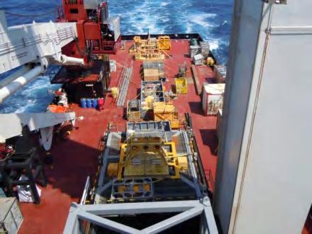
16 RPSEA PROJECT TASK 9 REPORT The bending guide limits curvature of the tubing between the reel and the injector and is used to establish and manage entry of the tubi ng into the i njector. The injector supports the dep loyed tubing and in turn is supported by the motion isolation system. The CT service contractor s equipment typically includes a CT BOP, a packer stripper, and a l ine for returns. These items can be installed either above or below the s upport point. Ther e are advantages to keeping deck loads low, so it is preferable to install this equipment below the point where the riser extension attaches to the motion isolation system. The slip rams at the bottom of the stack-up are normally engaged to seal around the tubing and to support the tubing if the injector requires maintenance. When used with the self supporting riser, these slip rams can be located below the r iser buoyancy, where they will also support the tubi ng following any emergency disconnection. 3.3 Vessel Interfaces & Deck Arrangements Figure 3.5 shows a typical arrangement for the riser components and installation equipment on the deck of a 260-foot vessel. Additional riser joints and additional buoyancy modules will be required for installation in deeper water. A larger vessel with more deck space and additional accommodations will be required if a single vessel is to install the riser, conduct CT operations, and carry adequate consumables for the downhole work. Riser Joints Crane Assembly & Deployment System Gas Umbilical ROV System Buoys BOPs ROV Vans Riser Vans FIGURE 3.5 TYPICAL DECK ARRANGEMENT FOR RISER INSTALLATION 16


17 RPSEA PROJECT TASK 9 REPORT An objective of the project is to do downhole work with vessels that cost less than half as much as a MODU. Figure 3.6 s hows deck arrangement for a typical but r elatively simple downhole intervention using a 260-foot vessel. The m ost significant aspect of using smaller vessels is that they are subject to greater pitch and roll motions. Isolation of the riser extension from these vessel motions is the primary function of the motion isolation system described in Section 5.2 and in the Appendices. FIGURE 3.6 TYPICAL DECK ARRANGEMENT FOR CT OPERATIONS 17
 is intended to meet all regulatory and industry requirements for emergency reservoir isolation.")

18 RPSEA PROJECT TASK 9 REPORT 4.0 SEAFLOOR SHUTOFF DEVICE The design of the Seafloor Shutoff Device (SSD) is intended to meet all regulatory and industry requirements for emergency reservoir isolation. It incorporates the B OP functions needed at the seafloor, including provisions to s hear and s eal coiled tubing or wireline with stored energy sufficient for close, open, and reclose cycling. A primary design objective is to enhance reliability by keeping it simple and avoiding complexity. The 7-3/8 bore is suitable for pulling crown plugs from horizontal trees having up to 7-inch completion tubing. The SSD illustrated in Figure 3.7 connects the bottom end of the s elf supporting riser to the subsea tree. The S SD has a 7-3/8" nominal bore, 10,000 psi maximum working pressure valve block with a modified 13-5/8 inch 10,000 psi API flange down and Vetco Gray TR style mandrel up. The 1 3-5/8 flange connects to a p roject specific adapter that mates with the client s tree running tool. The SSD valve block assembly is arranged in three modular sections. The upper mandrel section has a 7-3/8 10,000 psi gate valve rated to fail as is. The middle section incorporates a dual set of NOV Texas Oil Tools shear / seal rams. The lower section is an adapter between the r ams and the s pecific tree running tool. The shear / seal ram has a hy draulically operated ram cylinder and wedge type Autolock mechanism. The dual set of r ams has a nom inal 7-3/8-in bore with 9-inch 10,000 psi API 6BX flanges top and bottom. The r am cylinder is fitted with position indicators and is capable of s hearing 3-½-in OD coiled tubing with a to inch diameter logging cable inside and capable of subsequently achieving a blind seal. Additional detail is in the Appendix. Reservoir isolation capability is also provided by the near surface shear and seal device at the top of the SR and by the CT BOP in the riser extension to the vessel. The CT BOP provides all normal well control functions. This approach provides redundancy and shorter control lines for faster response, and locates most of the active equipment near the surface where it is readily accessible for maintenance. FIGURE 3.7 SEAFLOOR SHUTOFF DEVICE 18
19 RPSEA PROJECT TASK 9 REPORT 5.0 RISER DEPLOYMENT & MOTION ISOLATION Key requirements for equipment to install the riser and operate through it are in the task reports for Tasks 5 and 6. Thi s section summarizes work done by Huisman and R olls Royce Odim to further define hardware to meet the functional requirements. Material they prepared is included in the Appendices of this Task 9 report. Safety, reliability, and efficiency in that order are the top pr iorities in the design. Suitable safeguards are required to protect personnel from injury by moving parts. There are to be provisions for hand rails or similar barriers around the moon pool when the cover is not closed. A design target for the Gulf of Mexico is to work from small vessels, typically 260 feet in overall length, when separate vessels are used for riser installation and CT work. Both the riser installation and the m otion isolation system should be designed to spread the load over a sufficient area around the moon pool to avoid or minimizing the need to strengthen the associated area of a typical vessel of opportunity. Equipment for both riser installation and CT work may be integrated into a single package, but scheduling flexibility can be improved and offshore operations costs may be reduced substantially by installing the riser from a vessel that is not necessarily equipped for down hole work, and doing down hole work from a vessel that is not necessarily equipped for riser installation. Two configurations are presented in the A ppendix. O ne was prepared by Huisman working as a subcontractor, and the other contributed by Rolls Royce Odim acting as a potential supplier. Both configurations present an integrated system that can be used for both riser installation and CT operations. If installation and CT operations are to be done by different vessels, each vessel needs only those elements of the system appropriate to the specific task. Huisman suggests using a vessel outfitted with a Huisman tower crane. The Ross Candies and the Surf Challenger are mono-hull vessels with Huisman mini towers and are both believed to be operating in the Gulf of Mexico. These vessels need to be fitted with different moon pool covers, tongs, slips, and deck handling equipment for riser components. H uisman notes that continuous operation of the tower s heave compensation feature during CT operations will rapidly wear the wire ropes, and suggests modifications to extend the life. The Huisman report does not directly address vessel pitch and roll motions. The Rolls Royce Odim material in the A ppendix consists primarily of s tills from an animation to show how a system they built previously can be adapted to suit the needs of this project. Rolls Royce proposes to place a spider in the moon pool and a framework above the moon pool to handle the joints, buoyancy modules, and other components of the riser. Rolls Royce shows a trolley system for moving equipment on deck and a moon pool cover with slips and tongs. 19
20 RPSEA PROJECT TASK 9 REPORT 5.1 Riser Installation & Recovery Equipment Riser assembly functions include deck handling of the 25-ton Seafloor Shutoff Device, 20- ton buoyancy modules, and riser joints. Equipment is preferably moved by trolley to avoid swinging loads associated with crane lifts. The equi pment must assemble the riser by aligning joints and threading them with tongs, and then deploy the assembled joints and buoyancy modules through the m oon pool. Guides in the moon pool are required to control the buoyancy modules as they are lowered through the tur bulence in the moon pool during both deployment and recovery. The guide rails are to be spaced to suit the guide sleeves on the buoyancy modules and are to extend down below the keel of the vessel. For SSR recovery, provisions are needed for wires from constant tension winches to align the buoyancy modules guide sleeves with the guide rails before buoyancy modules are recovered through the moon pool. Slips in a split bowl are needed to support the weight of the suspended riser while the cover is closed. The slips are located in a split moon pool cover and must have provisions to prevent release due to inadvertent operation or slippage of the cover sections. It is intended to use low cost, readily available vessels. Minimizing deck space, deck load, and overall vessel size are therefore important design considerations. Futur e riser handling and assembly systems may be per manently integrated into dedicated vessels, but it is preferred that the first riser assembly system be suitable for rapid mobilization to a vessel of o pportunity. The installation equipment and the m otion isolation equipment should therefore be as small and light weight as is practical. Mobilization should consist primarily of lifting the installation equipment to the deck, fastening it, and connecting the power and c ontrol lines. Ideally the as sembly and deployment equipment can be transferred from the dock to the vessel in only two to three lifts, with additional lifts for the trolley system that moves equipment on deck. Riser joints, buoyancy modules, and other elements of the r iser can be m obilized on special pallets, bolsters, or racks to simplify the deck handling equipment. 20
21 RPSEA PROJECT TASK 9 REPORT 5.2 Motion Isolation System for CT Operations The SSR allows smaller, lower cost vessels to be used for CT work, but smaller vessels experience greater heave, pitch, and r oll movements which must be ac commodated by the riser / vessel interface equipment. A design target is to work from a 260-foot vessel with 6-foot to occasionally 8-foot significant height for combined waves and swells in the Gulf of Mexico, where the period for swells and waves is typically four to six seconds. Both self supporting and vessel supported risers are stationary with respect to the earth while the vessel moves with waves and swells. The inertia of the effective mass of the near surface buoyancy of the SSR alters the dynamics of the riser by resisting horizontal acceleration. The riser / vessel interface equipment for an SSR must therefore include provisions to avoid excessive bending moments in the upper part of the riser as the vessel moves in pitch and roll. In this regard it helps to engage the riser to the vessel near the vessel center of motion, typically inside the moon pool. It is also important to support the riser and injector in a manner that leaves the vessel free to pitch and roll without bending the riser. E ngaging the r iser extension in or close to the moon pool also helps avoid clashing between the riser and the walls of the moon pool. The maximum operating load for motion compensation during CT operations includes the weight of the tubing suspended below the vessel and the weight of the injector and the riser extension, plus any forces exerted by the tubing that runs between the reel and the injector. Dynamic loads due to nonlinearity of the motion isolation system add to the static vertical load which is typically less than 75 tons but may be 150 tons including allowance for the breaking strength of the tub ing. The d esign should not al low transients due to shearing or breaking the tubing to damage the equipment. The motion isolation system should be designed to work with a wide range of CT injectors, and to provide personnel access to the injector if maintenance is required while the tubing is deployed downhole. All reasonable steps should be ta ken to r educe the el evation of the i njector. High elevation of the load can adversely affect the stability of a s mall vessel. Also, access for insertion of the tubing into the injector and for injector maintenance is better if the injector is near deck level. The motion isolation system design shall include provisions for engaging the riser extension as close to the center of vessel motion as is practical, typically below the water line in the moon pool. Minimizing the stack-up height for the CT equipment reduces relative motion between the vessel and the injector. The power required for heave isolation is proportional to the load and maximum vessel heave and inversely proportional to the time period of the h eave cycle. The heav e cycle for Gulf of Mexico operations is typically six seconds. The load on the platform will change as tubing is run or pulled. The motion isolation system must maintain tension in the riser extension while the weight on the motion isolation system changes. The magnitude and tolerance for this tension is determined by riser analysis. The Task 6 Report defines three ranges of nominal tension and tolerance for normal, above normal, and exceptional vessel motions. Pitch and roll motions should be isolated by a system that does not require hydraulic or electrical energy from the vessel and prevent clashing between the riser extension and the walls of the moon pool. Introduction of bending moments into the riser extension should be avoided to prevent reduction in the fatigue life of the SSR or the riser extension. 21
22 RPSEA PROJECT TASK 9 REPORT A telescoping joint in the riser extension can be used as an alternative to a deck mounted motion isolation system. The tel escoping joint allows the injector to be fi xed mounted to the deck of the i ntervention vessel. The depl oyed tubing moves up and down in the well as the vessel heaves, but this motion is not a concern in relatively low sea states for jobs such as well cleanouts. The telescoping joint approach is not appropriate when vessel heave motion is large or when the lower end of the coiled tubing must be fixed in place as, for instance, in drilling applications. 22
23 RPSEA PROJECT TASK 9 REPORT 6.0 TUBING HANDLING FOR LONGER FATIGUE LIFE An objective of this project is to do downhole work with vessels that cost substantially less than a MODU. Lower cost usually implies smaller vessels, and smaller vessels are subject to greater pitch and roll motions in any given sea state. Thi s section addresses provisions to protect the tubi ng from fatigue due to v essel motions while the deployed tubing is held stationary in the well. The baseline system includes a preferred equipment arrangement for handling the tubing on deck in a m anner that minimizes the effec t of v essel motions on tubing fatigue life. With these provisions, analysis shows satisfactory fatigue life for various combinations of CT internal pressure pitch and r oll motions up to 10 degr ees. A nalysis shows that the preferred arrangement exerts only reasonable side loading on the top of the riser. It also shows that the pr eferred arrangement enhances overall tubing fatigue life beyond that seen in the traditional onshore configuration by not bending the tubi ng sharply over the gooseneck. Both fatigue life of the tubing and stability of t he vessel are improved by keeping the injector close to deck level. Mounting the CT reel on the motion isolation system will eliminate relative motion but will require a larger stabilized platform, and additional power will be needed to c ompensate the weight of the r eel and reel drive, with only a relatively small gain in fatigue life. CTES created a model that distinguishes between elastic and plastic flexing, and used the model to evaluate different equipment arrangements for handling the tubing between the reel and the injector. Fatigue life is improved by avoiding tension in the tubing segment where the fl exing occurs between the reel and the injector. In the most common arrangement for onshore use this tension is kept high to keep the c oil tight on the r eel. The CTES analysis is based in part on using a mini injector to pull the tubing off the r eel so that there is no tension between the reel and the injector. As an enhancement, over-bend rollers on the reel s level wind can alternately shape the tubing to the diameter of the reel or the diameter of the arc as the tugging is reeled and unreeled, respectively. This approach keeps the tubing tight on the r eel while reducing tension on the reel and avoiding tension in the arc. Over-bend rollers are similarly used on reel pipe vessels to shape the pipe to t he reel diameter for reeling and then to straighten the pipe as it is laid. This process is common for 8,000 to 10,000 psi pipe with diameter of 10 inches or more, and is comparatively easy for 1.5 to 3-inch tubing. A second set of over-bend rollers can be installed above the injector to straighten the tubing from the radius of the arc as tubing is run into the riser, and to s hape the tubing to the nominal radius of the arc as tubing is pulled from the riser. Avoiding tension in the tubing between the reel and the injector also improves the bending moment in the riser and reduces the side load on the injector, thereby simplifying the task of keeping the riser extension centered in the moon pool. The analysis showed that, since the preferred arrangement avoids tension in the tubing between the reel and the injector, side loading on the riser is typically only a few hundred pounds. The equipment configuration described above is similar to the onshore application shown in Figure
24 RPSEA PROJECT TASK 9 REPORT FIGURE 6.1 PARABOLIC ARCH EQUIPMENT CONFIGURATION (LAND) 24
25 RPSEA PROJECT TASK 9 REPORT The position of the level wind device can be adjusted to accommodate different separation distances between the reel and the injector. Figure 6.2 shows the shape of the a rc with the reel closer to the injector and the level wind closer to the deck. FIGURE 6.2 SHAPE OF TUBING ARC WITH REEL CLOSE TO INJECTOR The analysis by CTES was based in part on vessel motions shown in Figure 6.3. The figure shows heave, pitch, and roll data taken onboard a representative 264-foot vessel headed into the weather in seas reported to be thr ee to five feet, occasionally six feet, with wind gusts to 20 k nots. As can be seen in the figure, maximum heave was about 2.5 feet while maximum pitch and roll angles were 2 to 2.5 degrees. Data was not recorded, but observations on a similar vessel indicated maximum pitch of appr oximately 9 degrees while headed i nto eight to el even0foot seas associated with a winter front in the Gulf of Mexico. 25
26 RPSEA PROJECT TASK 9 REPORT FIGURE 6.3 REPRESENTATIVE MOTIONS OF 264 FOOT VESSEL The period of the motions varies and appears to average about six seconds, or about 10 cycles per minute, which is typical for the Gulf of Mexico. Examination of the curves in the CTES report (see Appendix) shows an anticipated fatigue life due to vessel motions of several hundred to a thousand hours for pitch and roll of five degrees. Sea state probability varies with season and location, but limiting operations to sea states causing less than 5 degrees pitch and roll for a 260-foot vessel should typically allow operations four to five days a week in the winter, with summer operations interrupted primarily for named storms. Curves, data tables, and more specific information are included in the CTES report Appendix. 26
27 7.0 APPENDIX RPSEA PROJECT TASK 9 REPORT I. Seafloor Shutoff Device a. H b. H c. H d. H e. H f. Controls with shuttle valves g. Text and Cost Material II. Riser Installation & Motion Isolation a. Rolls Royce sequence of still frames from animation b. Huisman Well intervention system vessel 2 c. Deck photos of Ross Candies III. Fatigue life analysis for Deck Handling of Coiled Tubing a. Analysis of CT Utilizing a Parabolic Arch Configuration b. CT Software Modeling Inputs Theory & Validation 27

28 RPSEA PROJECT TASK 9 REPORT Seafloor Shutoff Device (SSD) Part No: - H Functional Description The Seafloor Shutoff Device (SSD) is used during Coiled Tubing well intervention phases to provide control of the well. The SSD is installed at the bottom end of the Workover Riser String and connects the subsea tree to the workover riser string. The SSD has a 7-3/8" nominal bore, 10,000 psi MWP (Maximum Working Pressure) valve block with a 13-5/8"- 10,000 psi API (American Petroleum Institute) flange (modified) down by Vetco Gray TR style mandrel up. The 13-5/8 flange down will be connected to a project specific adapter designed to connect with the client provided tree running tool. The bore configuration is designed to allow free passage of wireline and coiled tubing tools. The 7-3/8 through bore will accommodate the typical 7 crown plug of horizontal trees. The SSD valve block assembly is arranged in three modular sections consisting of the upper mandrel section with a 7-3/8 10,000 psi gate valve, Fail As Is (FAI). The middle section incorporates a dual set of NOV Texas Oil Tools shear/seal rams. The lower section is an adapter between the rams and the specific Tree Running Tool (TRT) configuration. The NOV Texas Oil Tools Shear/Seal Ram (SSR) has a hydraulically operated ram cylinder and wedge type Autolock mechanism. The dual set of rams has a nominal 7-3/8 bore with 9"-10,000 psi API 6BX flanges top and bottom. The ram cylinder is fitted with position indicators and is capable of shearing 3-1/2" OD coiled tubing with a to diameter logging cable inside and subsequently capable of achieving a blind seal. TR Mandrel and Connector 7-3/8 10M, FAI, WLS Valve 7-3/8 10M, Shear/Seal Dual Rams Project Specific Adapter Typical Tree Running T l The SSRs have dial position indicators. Indication is provided by means of rack and pinion arrangement, the rack being fitted onto the piston rod while the pinion arrangement is housed in the cylinder. The pinion end is attached to an indicator with a calibrated dial; position indicators are viewed by the ROV. The SSD has one Production Isolation Valve (PIV) arranged for Wireline Shear (WLS) which has cut the following during shear tests: 28
29 RPSEA PROJECT TASK 9 REPORT a) n Coiled Tubing x WT (Gr HS-90 CM) with n Hepta cable inside b) n Hepta cable c) n Slick line The valve is a 7-3/8"-10,000 psi MWP with a hydraulic actuator. The actuator has a linear ROV override and a position indicator. The hydraulic actuator is Fail As Is (FAI) and operates with control pressure of 5,000 psi. The lower adapter is fitted with a 2-10,000 psi MWP valve to facilitate annulus access. Alternatively, the annulus isolation valve can be assembled to a spool that offers communication between the tree annulus bore and the SSR. The valve and spool arrangement provides for circulation/bullheading of the production tubing if the subsea tree can accommodate. The Annulus Isolation Valve (AIV) is a 2-1/16"-10,000 psi MWP with FSC (Fail Safe Close) hydraulic actuator. The actuator has a linear ROV override and position indicator. The backside of the valve actuator chamber (compensation side) is filled with Marsten Bentley HW 443 (or project specific) water-based lubricant and is linked to a volume compensator (un-pressured accumulator known as a sea chest ). The reverse side of the sea chest is open to ambient seawater pressure. Two check valves, one inlet and one outlet, are mounted to the sea chest manifold. They are designed to prevent any pressure build up from occurring in the compensation system. The SSD valve seat pockets and all sealing surfaces are Inconel 625 clad. The mandrel has a 9"- 10,000 psi API 6BX flange which mounts to the SSR block. The mandrel has a 7-3/8 nominal through bore which terminates with a SSD seal pocket at the top. Incorporated into the SSD frame are the following: ROV Hot Stab Receptacles ROV Cut Lines ROV Docking Panel Protection from Dropped Objects Mounting for Accumulators Guide funnels for standard API guide post features Technical Specification Maximum Operating Pressure: Service: Hydraulic System Operating Pressure: Weight (Est.): 10,000 psi Production and Annulus NACE MR ,000 psi - See schematic drawing H ,000 Lbs. Size 144 x135 x169 -See Drawing H
30 RPSEA PROJECT TASK 9 REPORT Ram Hydraulic Operating Volumes Pair of Actuators including Autolock: SSR Ram Close: 5.95 Gallons (TBC) SSR Ram Open: 7.75 Gallons (TBC) Valve Hydraulic Operating Volumes: 7-3/8 FAI WLS Open 2.20 Gallons 7-3/8 FAI WLS Close 2.20 Gallons 2-1/16 FSC 0.13 Gallon Temperature Range: -20 F to 250 F Lubricants: General: Jet Lube Alco EP-73 Plus Valve Gates/Seats: VGS Hydraulic Controls: Per Project Requirements Fluid Cleanliness SAE AS4059 6B-F Valve Compensation Side: Marsten Bentley HW 443 Bolt Threads: Never-Seez or Kopr Kote Handling Equipment: Bore-Size (Drift): Upper Connection: Lower Connection: Upper Seal Groove: Lower Seal Grooves: SSD Valves/Rams: Main Body Material: Frame Material: Bolting Material: Single Point Lift Cap (A ) Dedicated Sling Set (H ) Handling Clamp (Shop Use - H ) 7-3/8" Thru Bore with 2-1/16" Outlets (Lower Adapter configuration dependent) 16 TR profile mandrel 13-5/8 10 API Flange (Modified) (Dependent on TRT interface) 7-3/8 SSD Seal Pocket Based on Specific Intervention Shear/Seal Rams (SSR) (Dual Set) Production Isolation Valve (PIV) Annulus isolation Valve (AIV) VGS , 2-1/4 CR 1 MO, 80 KSI ASTM A36 ASTM A320 L7 Seal Area Cladding: Inconel 625 Coating Paint (Except Mandrel): Mandrel Coating: VGS (Three Coat Epoxy) VGS6.2.3 (Phosphate) 30
31 RPSEA PROJECT TASK 9 REPORT 31
32 RPSEA PROJECT TASK 9 REPORT 32
33 RPSEA PROJECT TASK 9 REPORT 33
34 RPSEA PROJECT TASK 9 REPORT 34
35 RPSEA PROJECT TASK 9 REPORT 35
36 RPSEA PROJECT TASK 9 REPORT 36
37 RPSEA PROJECT TASK 9 REPORT 37
38 RPSEA PROJECT TASK 9 REPORT 38
39 RPSEA PROJECT TASK 9 REPORT 39
40 RPSEA PROJECT TASK 9 REPORT Appendix I. Cost Estimate For Seafloor Shutoff Equipment cost estimates for the seafloor shutoff are listed in Figure 7.1 as refinement of the preliminary estimate included in the Task 6 Report. The seafloor shutoff device meets the requirements described in the Task 6 report, and assumes that the Operator will provide the tree interface connector from the tree running tool or his completion and workover riser. The cost for equipment to assemble and deploy the riser and the cost for the motion isolation system for downhole work depend heavily on how the specific vessel was previously outfitted. Estimates for these costs are therefore not included in this report. COST ESTIMATE FOR SEAFLOOR SHUTOFF DEVICE WITH CONTROLS Item Unit cost Qty Cost Engineering & project management 500, ,000 Seafloor shutoff device with shipping frame and test stand 2,883, ,883,000 Controls package 1,300,000 1,300,000 Hydraulic Power Unit 150, ,000 Umbilical on reel for seafloor shutoff device & tree with termination assembly & breakaway 2,800, ,800,000 Subtotal $7,633,000 40


41 RPSEA PROJECT TASK 9 REPORT Appendix II. SEQUENCE OF STILL FRAMES FROM ANIMATION OF ROLLS ROYCE RISER INSTALLATION SYSTEM Casing joint installation starts. Skate move to centerline of deck and prepares to receive riser joints Joint handler places riser joint on the skate 41


42 RPSEA PROJECT TASK 9 REPORT Skate presents joint to tower Elevator accepts upper end of the riser joint 42


43 RPSEA PROJECT TASK 9 REPORT Elevator upends riser joint and aligns it with previously installed riser joints Tongs engage riser joint to previously assembled joints 43


44 RPSEA PROJECT TASK 9 REPORT Elevator lifts string to release slips, lowers string, and hangs new joint in slips (as seen from operator s cabin) Skate is parked and moon pool cover is made ready for buoyancy module 44


45 RPSEA PROJECT TASK 9 REPORT First buoyancy module moves to approach moon pool Weight of previously assembled joints is transferred to spider in moon pool, moon pool cover opens, and rails are swung into place over moon pool 45


46 RPSEA PROJECT TASK 9 REPORT Buoyancy module moves over moon pool (uppermost buoy with near surface shear and seal is illustrated here) Elevator engages top of joint that runs through the buoyancy module 46


47 RPSEA PROJECT TASK 9 REPORT Elevator lifts buoyancy module, trolley moves back, and moon pool opens Spider lifts previously assembled string and weight is transferred to slips in moon pool cover 47


48 RPSEA PROJECT TASK 9 REPORT Elevator lowers buoy and aligns joint through buoy with the top of previously assembled string Joint through buoy is connected to the previously assembled string and elevator lifts weight of string off the slips 48


49 RPSEA PROJECT TASK 9 REPORT Elevator lowers string through moon pool while guide rails on spider keep the buoy centered in the moon pool until it clears the keel Injector support frame moves over the moon pool for CT operations 49

50 RPSEA PROJECT TASK 9 REPORT Appendix II, Section b Worldwide Lifting, Drilling and Subsea Solutions Technical Specification Motion Isolation System 50
51 RPSEA PROJECT TASK 9 REPORT Technical Specification Motion Isolation System TABLE OF CONTENTS 1 GENERAL INTRODUCTION DESCRIPTION 4 2 DESIGN CONSIDERATIONS GENERAL CONSIDERATIONS RISER INSTALLATION CT OPERATIONS LIFTING TOWER PARTICULARS 6 3 SYSTEM OVERVIEW SYSTEM LAYOUT AND OPERATIONAL PROCEDURES EQUIPMENT DESCRIPTION MULTI PURPOSE TOWER SPLITTABLE TRAVELLING BLOCK AND DUAL DRAWWORKS (OPTIONAL) ACTIVE HEAVE COMPENSATION PASSIVE HEAVE COMPENSATION AUXILIARY TROLLEY AUXILIARY TROLLEY WINCH CATWALK MACHINE MT PIPE HANDLING KNUCKLEBOOM CRANE SERVICE CRANE CONTROLS MOVING HATCH PIPE MAKE UP EQUIPMENT 19 6 DEMONSTRATION PROJECT Huisman Equipment BV Admiraal Trompstraat HH Schiedam The Netherlands Harbour no. 561 Phone: sales@huisman-nl.com 51

 are either too expensive or not")

52 Well Intervention System Technical Specification 1 GENERAL 1.1 Introduction As is widely known not all available oil is recovered from existing wells. Well intervention can play an important role in prolonging the life of existing fields and increase the total production. However, the current vessels that are capable of doing heavy well intervention (deeper water depths, deep wells) are either too expensive or not readily available. This report describes a system to be installed on a small vessel but with the same capabilities as larger vessels. Figure 1 depicts the different vessels on the same scale, showing the potential of this new concept. 50,000t displacement drilling vessel Optimized drilling vessel 1st generation intervention vessel GOAL Smaller and more versatile vessels 2nd generation intervention vessel Figure 1 Well Intervention capable vessels to scale 52

53 Well Intervention System Technical Specification 1.2 Description The Motion Isolation System (MIS) has been designed in accordance to the requirements stated in paragraph 7.2 and paragraph 3.0 of the RPSEA Task 5 Final Report. The important design parameters are: Water depth 10,000 [ft] TVD 5,000 23,000 [ft] Vessel Heave 10 [ft] Riser 6 5/8 DP [inch] Buoyancy Modules 14 [ft] (diameter) No of Buoyancy Modules 4 [-] Maximum vessel offset 3 [%] Operational 4 [%] Disconnect The system layout is presented in figure 2. CT Tool Surface BOP Buoyancy Section Riser Section SSSD Figure 2 System Layout 53
54 Well Intervention System Technical Specification 2 DESIGN CONSIDERATIONS 2.1 General Considerations The design was based on the fact that the installation operation should be performed in a safe and efficient manner. The installation of the free standing riser involves moving a large number of heavy pieces of equipment to and from the moon pool. In order to ensure safe operations the design of the Motion Isolation System (MIS) does not allow for any free swinging load handling. All loads are locked to prevent free motions until the moment that the equipment is run toward the seabed. To add to safety, work at elevated heights is avoided as much as possible. As a consequence some equipment will be located below the sea level. This is considered an acceptable trade-off. The height of the lifting tower is determined by taking the following effects in consideration: - Vessel motion (+/-3m) - Vessel offset (max 3m vertical deflection) - Required maintenance height - Safe lowering to the seabed while in heave compensation mode - Safe retrieval of objects from the seabed - RIII (45 ) riser joints - 60 Slipjoint - Riser expansion due to internal pressure - Running tool length - Height of different pieces of equipment - CT tool length of 25 When looking at the weights and installation heights it appears that for both the riser installation and the CT jobs the same system can be used in terms of hookload and required lifting height. # 1 STAGE Installation A DESCRIPTION Lower equipment from Xmas tree up to buoyancy modules SWL (t) Installation B Lower equipment from Injector to BOP 40 3 Installation C Install CT Equipment 75 4 Installation D Operate CT + ballasted riser string (overpull = 10t) Operational E Riser Tension (pressurized) 50 6 Operational F Riser Tension (depressurized) 140 In this report only one system layout is described to accommodate both operations, CT operations and Free Standing Riser build up. Exact specifications of equipment are not known in this phase of the project. The specifications have been drawn up in such a manner that a wide range of equipment can be accommodated. The equipment can be designed somewhat more compact when more exact information is available. 54
55 Well Intervention System Technical Specification 2.2 Riser Installation The riser installation is a relatively straightforward operation. The advantage of the free standing riser concept is that the final connection can be made using wire instead of dynamic positioning (DP). This is due to the fact that the top of the riser is more than 100 feet below sea level. This greatly simplifies the layout of the handling equipment on the deck, and also simplifies procedures. In the design threaded couplings are used to connect the different riser sections. The advantage is that readily available equipment can be used. 2.3 CT Operations The most critical part of the CT operations is the tool change out phase of the operation. In this phase the riser stays connected to the seabed but the CT injector has to move with the vessel; thus there is a relative motion between the two. There are three options possible: 1. Slipjoint, which can move without pressure and is fully extended with internal pressure (BLAFRO system ). 2. Fully pressure compensated slipjoint, Which is not currently available, but conceptual designs are already made. 3. CT equipment is connected and disconnected using the active heave compensation system. The riser stays connected to the seabed, but the CT can be lifted a certain distance from the riser. Disadvantages are complex; additional tower height is needed and there is limited tool height during change out. For this report the BLAFRO system is used as a base case. 2.4 Lifting Tower Particulars Main mast hookload (static) 270 [t] 586 [kips] Main mast hookload (dynamic) 200 [t] 440 [kips] Free lifting height main mast (below travelling block) 30 [m] 95 [ft] Lifting speed 30 [m/min] 95 [ft/min] Max Vertical HC motion +/-2 [m] 6.5 [ft] Draw works main mast 1250 [kw] 1,600 [HP] Moon pool Size 7.2x7.2 [m] 23.5x23.5 [ft] During the concept phase different design options have been considered to lift and move equipment into position. The main design criterion is to hold the load to prevent free swinging motions and the movement from horizontal storage position into vertical position. When transferring pipe one can use normal pipe handlers with articulated grippers. The difficulties arise when moving the CT equipment from horizontal to vertical position. This equipment is too heavy to handle with standard pipe grippers. 55
56 Well Intervention System Technical Specification The tower design combines the two functions, load holding and rotation, into one device and is the preferred option. Considering the heave compensation system, in order to keep the power low, the weight the HC system has to move is to be kept at a minimum. In the tower option this only involves the travelling block, whereas in the platform option this could incorporate the whole platform. Figure 3 Different Concept Solutions 56

57 Well Intervention System Technical Specification L1Huisman J TO MOON POOLMOON POOL CENTER 3600 [11'-9.?3"[ FRONT VIEW' LOOKING AFT SIIE VIH/ LOOKING 56TD 1J045 [42'-9.61"[ Figure 4 -MPT General Arrangement 57

58 Well Intervention System Technical Specification Installation on the vessel One of the design criteria of the motion isolation system is its capability of being mounted on vessels of opportunity. The Huisman tower is very well suited for this provided that some basic preparations have been done. The tower is completely self-contained: all drives, control systems, etc. are mounted inside the mast. This system makes long term storage easy. Also, the installation on the vessel is simplified because it only requires one single lift. The mast introduces significant forces into the vessel and these must be accommodated. There are potential technical solutions: - Dedicated vessel - Generic interface frame welded to the tower - Dedicated interface frame bolted to the tower. Reviewing the stress plots below, it is clear that the high stresses are confined only to the tower only. The force readily dissipates when flowing into the vessel structure. Using a dedicated vessel, the vessel structure can be reinforced internally where necessary to accommodate the tower forces. The intermediate frame should be designed in such a way that any connections to the vessel do not exceed the maximum allowable stresses for the vessel structure. It will require an intermediate frame that has a larger footprint compared to the tower. Depending on the similarity between available vessels of opportunity, a generic intermediate frame can be used. Otherwise, a different frame for each vessel needs to be made. 58
59 Well Intervention System Technical Specification 3 SYSTEM OVERVIEW The main function of the Well Intervention System is the handling and deployment of subsea equipment, e.g., the well intervention package including the High Pressure Riser. The Huisman Well Intervention System is composed of the following main elements: Multi Purpose Tower (MPT), including load motion damping device Dual draw works Active Heave Compensation (AHC) Passive Heave Compensation (PHC) Catwalk machine 12mt knuckle boom crane Control system Service crane Skidable moon pool door with hang of assembly interface 3 Deck skid carts Pipe Make Up equipment. Riser Tensioner (not described in this report). Also necessary is a CT support frame. This is not detailed in this report because it needs to be closely matched to the CT equipment. 59

, since they are easier to handle.")


60 Well Intervention System Technical Specification 4 SYSTEM LAYOUT AND OPERATIONAL PROCEDURES The Multi Purpose Tower (MPT) is positioned at the side of the moon pool. This allows for easy access to the firing line. The MPT is the main component of the system and is used to run various pieces of equipment to the seabed. The distance that the travelling block can cover is limited to the height of the tower. Running subsea equipment to the seabed is to be performed using the High Pressure Riser. Slings can be used for the final distance ( feet), since they are easier to handle. Several different deck layouts were investigated: - port side (PS) - starboard (STB) - Centre Of these three locations the SB/PS layouts are considered to be the most optimal. There are three main advantages: 1. The skid rails of the carts can continue over the hatch, simplifying the skidding procedures. 2. Crane access is improved around the tower 3. Riser pipe can now be stored forward of the tower, creating a more efficient use of deck space. The MPT is fitted with two trolleys. The main trolley is fixed to the travelling block and travels up and down the tower. The auxiliary trolley travels up and down the MPT by means of its own dedicated winch, and is used to guide equipment that is suspended in the tower. The auxiliary trolley prevents swinging loads and thus provides a safe and controlled way for offshore lifting. The 12-metric tonne knuckle boom crane is strategically positioned on the main deck and can cover the moon pool area and the firing line. The main purpose of the knuckle boom crane is to handle the tubulars and feed them onto the catwalk machine. Due to its position, the 12-metric tonne Knuckleboom crane can also be used to maneuver small tubulars directly into the firing line. This creates a level of redundancy. The catwalk machine is positioned on the ships centerline and used for the horizontal transport of tubulars. The catwalk machine receives tubulars from the 12-metric tonne knuckle boom crane and transports them into the firing line where they are handed over the elevator, which is suspended from the travelling block. 60
 Auxiliary trolley Service crane Dual Draw works Internal access Crown")
61 Well Intervention System Technical Specification 5 EQUIPMENT DESCRIPTION 5.1 MULTI PURPOSE TOWER The Multi Purpose Tower comprises: One fully welded box girder structure Main Trolley (travelling block) Auxiliary trolley Service crane Dual Draw works Internal access Crown Block MPT The Multi Purpose Tower (MPT) including the integrated crown block is built as a box girder type main structure. The box structure provides both the main loadcarrying element and an enclosed environment for the following equipment: Passive Heave Compensation cylinders Hydraulic Power Unit (HPU) Electrical cabinets All integrated equipment is accessible on dedicated floors that can be reached by way of internal stairways. Splittable travelling block Moon pool Trolley Dual Draw works Features - Open firing line allows easy access from three directions - Small Footprint - Dual draw works on main hoist-+ no slip and cut procedure needed - Active and passive heave compensation on the travelling block - Use of Splittable block for increased hoisting efficiency and speeds (optional) - Auxiliary Trolley to provide controlled handling of subsea equipment - Service crane on top of MPT Figure 1: Example of 150 mt MPT as delivered to Helix. Note that the MPT presented in this proposal is only equipped with 3 drums; 2 main drums and one auxiliary hoist drum. 61
 The Splittable Travelling Block of the Multi Purpose Tower comprises two fixed and four detachable single sheave blocks.")

 electric-driven, double drum system. The dual drum system with two fast lines reduces the overall line speed and reduces line wear.")

62 Well Intervention System Technical Specification 5.2 SPLITTABLE TRAVELLING BLOCK AND DUAL DRAWWORKS (OPTIONAL) The Splittable Travelling Block of the Multi Purpose Tower comprises two fixed and four detachable single sheave blocks. Splitting the blocks is a push-button operation and is achieved by detaching a pair of sheave blocks from the main trolley and attaching them to the crownblock. Only when the main trolley is in its upper position can this operation be performed. The picture below shows the travelling block in a 12 falls, 8 falls, and 4 falls configuration. 12 falls reeving 8 falls reeving 4 falls reeving Load Load Load Reeving diagram with detachable single sheave blocks from12, 8, and 4 falls The dual draw works that move the travelling block consist of an independent alternating current (AC) electric-driven, double drum system. The dual drum system with two fast lines reduces the overall line speed and reduces line wear. It also provides built-in redundancy due to the fact that if one winch fails the other winch can still operate the travelling block, however at half the original speed. Splittable block The dual drum system does not have a deadline anchor and does therefore not require the conventional cut- and slip procedure. When a certain part of the wire is worn out, the complete drill line can be transferred a certain distance from one drum to the other, exposing a different part of the wire to a fatigue sensitive location (e.g., a sheave). After a certain period, the complete wire must be replaced. Main trolley Splittable block and main trolley 62
 System actively counteracts the vessels heave motion in order to place subsea equipment on the seabed in a controlled manner.")
63 Well Intervention System Technical Specification 5.3 ACTIVE HEAVE COMPENSATION The Active Heave Compensation (AHC) System actively counteracts the vessels heave motion in order to place subsea equipment on the seabed in a controlled manner. With AHC the real-time signal of the Motion Reference Unit (MRU) is used as an input signal: no wave or motion prediction methods are used. In response to this signal the E-motors turn the winches so they take in or pay out wire to keep the load at a constant position in relation to the seabed and minimize the differences in line pull. AHC is utilized during installation of subsea equipment. O nce the equipment is in place the passive heave compensation takes over. 5.4 PASSIVE HEAVE COMPENSATION After landing the subsea package using the AHC, the passive heave compensation takes over. The vertical motions of the vessel with respect to the seabed are now compensated by the passive heave cylinders. When the vessel moves upwards, the line pull increases and the cylinders are pulled upwards, paying out wire and reducing line pull. When the vessel moves downwards, the line pull decreases and the cylinders move downwards, hauling in the wire. The stiffness of the gas-loaded spring system can be adjusted by varying the gas volume that is connected to the passive system. This means that for each load case and for each sea state condition the gas volume can be optimized. By varying the pressure of the gas, the system can be adjusted to different static loads. The system is correctly set when the compensation cylinder is at the middle of its stroke and the line pull caused by the cylinder is equal to the nominal line pull in the wire. 63


64 Well Intervention System Technical Specification Pressure Vessels, gas pressure Load Gas Oil Protection System cylinders or Passive Heave Compensator Medium separator Rotating winches - Active heave Compensator 5.5 AUXILIARY TROLLEY The auxiliary trolley is driven by its own dedicated winch and provides a means of extra guidance for the packages in addition to the main trolley. The auxiliary trolley can be equipped with an extension frame that can be bolted on or off. Different frames can be attached to guide different sized packages. The auxiliary trolley can travel all the way down inside the moon pool and is utilized for package deployment, package retrieval, and package stack-up operations. 64

65 Well Intervention System Technical Specification 5.6 AUXILIARY TROLLEY WINCH The trolley winch is connected to the auxiliary trolley with one single wire and requires no back tension facilities. The auxiliary trolley moves on gravity. The auxiliary trolley winch is a regular drum winch that is mounted in a winch frame inside the MPT. The trolley winch is fitted with a constant tension control arrangement to avoid slack rope. This arrangement measures the load on the electric drive as a reference for the load. 5.7 CATWALK MACHINE The catwalk machine is positioned on the ship s centerline and is used for the horizontal transport of tubulars. The catwalk machine receives tubulars from the 12-metric tonne knuckle boom crane and transports them into the firing line, where they are handed over to the elevator, which is suspended from the travelling block. The tubular transport is carried out by the catwalk machine s conveyor belt. The belt moves the tubulars until the first end of the pipe is in the firing line. The elevator then lifts the pipe. When the pipe is nearly upright the tailing arm on the Catwalk Machine safely guides the tubulars into the firing line. If required, the catwalk machine can travel as a whole in forward and aft direction to make way for the moon pool hatch. The Catwalk machine consists of: - One main frame with wheels - Tailing arm - Conveyor The catwalk machine is controlled from the control cabin, Firing line Tailing arm Conveyor belt Tubular Wheels Catwalk machine 65


66 Well Intervention System Technical Specification MT PIPE HANDLING KNUCKLEBOOM CRANE The 12-metric tonne Pipe Handling Knuckle Boom Crane consists of a crane house, a main boom, and a knuckle boom that is outfitted with a gripper for tubulars. The driver cabin is mounted on one side of the crane house, while the hydraulic power unit is mounted on the other side of the crane house. Normally control and operation of the crane and the gripper shall be from a portable wireless remote control panel. Main hoist On the end of the knuckle boom, a gripper on a slewing device is mounted. The slewing device offers excellent handling of tubulars. Luffing/slewing Main boom luffing and knuckle boom luffing is done by hydraulic cylinders. The slewing is done by multiple hydraulic motors, gearboxes, and a fully enclosed slew bearing. The pipe handling crane will be installed on one side of the pipe deck, while designed for the following operations: Picking up or placing tubulars on the catwalk machine using the gripper head Handing tubulars or taking small tubulars directly out of the firing line. General deck-to-deck operations on the deck and main deck area within reach of the crane 5.9 SERVICE CRANE On top of the MPT a service crane is fitted. This hydraulic foldable marine crane will be powered by a hydraulic power unit (HPU). The crane is outfitted with a hydraulic wire rope winch with a non-rotating wire rope. This winch is also suitable for man-riding. The service crane can be operated with a remote control unit. 66

67 Well Intervention System Technical Specification 5.10 CONTROLS The Well Intervention MPT will be controlled from a dedicated control cabin. This cabin will be outfitted with windows to have a clear view on the tower, lighting, heating; an AC-unit, a door, and a work desk. Drop-in panels containing all controls associated with the system will be delivered and installed. Also, the necessary screens will be installed to monitor the systems and with views on the winches. The main operator will be seated in a chair without controls. On both sides control desks will be provided with the above mentioned controls. Drop-in panels for clients can be installed upon request but no provisions are made at this stage. The Well Intervention MPT will be controlled with a supervisory control and data acquisition, or SCADA, based system and will be completely developed by Huisman. Huisman has ample experience in designing and building SCADA systems Moving Hatch The moon pool hatch is a welded steel structure of approximately 7.3 x 7.3 meters squared. The hatch is able to skid in a transverse direction by means of hydraulic skid units which are mounted on top of two skid rails. The T-type skid rails need to be welded to the deck of the vessel. The hatch is supported in closed position on support around the moon pool. Therefore the hatch can only support the payload when the hatch is fully closed. The main functions of the moon pool hatch are: Support of the payload before it is lowered to the seabed Closure of the moon pool. The hatch has one central slot for the main hoist wire. Additional slots can be accommodated as required. The central slot can be closed by two hydraulic operated doors. The remaining moon pool opening of 1 meter diameter can be closed with a manually installed steel cover. On top of the hatch, two integrated skid rails will be welded for the skidding system. For the central slot a manually installed skid rail will be delivered. Controls The hydraulic movements of the hatch are fed via a drag chain by an electro-hydraulic power unit, which will be located near to the hatch. On the HPU a basic operator stand is located with the following control functions: - Lever for Push / Pulling - Lever for Clamping - Main switch for start up and stop of HPU - Emergency stop Skid rails The steel skid rails are HEM 260-type and the centre-to-centre distance between these rails is 2250 millimeters. The skid rails need to be placed on deck supports (not in Huisman scope of supply). 67


68 Well Intervention System Technical Specification 5.12 Pipe Make Up Equipment Huisman advises using an automated pipe make-up tool. A good example of this is the CanRig tool, which is a complete functioning unit including an articulated joint. The advantage of this tool is that it combines several tools into one which do not have to be mounted/ bought separately. 68
.")
 systems of those towers are not suited for prolonged periods when the HC is switched on (wire fatigue issues).")
69 Well Intervention System Technical Specification 6 DEMONSTRATION PROJECT It is intended to validate the concept of the free standing riser in a short period of time with minimal investments. There are two vessels working in the GOM on which a MPT is installed: the Ross Candies and the DMT Emerald (now Surf Challenger). Both vessels are capable of running the free standing riser to the seabed. Ross Candies Surf Challenger However, the heave compensation (HC) systems of those towers are not suited for prolonged periods when the HC is switched on (wire fatigue issues). Therefore, CT operations are not possible with these vessels without major modifications. In principle no major modifications need to be done on the vessels, provided that the installation takes place in calm weather. A skidding system is only needed for the riser pipes. The buoyancy cans are moved into position with the knuckle boom crane. This is not the optimal way of handling but it saves considerably on equipment cost. If confined to calm weather operations, no retrieval load damping device is needed. Necessary modifications: - Strengthen the hatch if necessary - Install riser spider - Install pipe make up equipment - Install Air compressors and hoses for filling up the buoyancy cans 69
70 Well Intervention System Technical Specification DESIGN INPUT!';TAf[Htn toad OYNN1[ tqj KlQNJ SP[[D IJYNN1( FN:TIJ=I N_HIDI{"TI!Am!POOL TR f'tll N GHK»<c ; "' :3':16 ntc5a6 t l lqq ntcr( 4-k Vsl,:;tl fl/mil'l l ljl-\zi\1 :Jl n = 7l00 lloo,, falls!!. 11'1 S11EAV1'> 1 teayeeompemoalon :!3 fl RJR FALL::!: 6n FeR FltlS ::,' "' 'w n ' m """' IRU!0/d EN'!OTY TQT!L ihave 5 u "'-" IRU!Old \'lll E [WilDT ; 30 z JIBuf.36 nn :J:l ndxl =HO fll(tui ' -"Lt Mel :(!, ra :3D z 72 rn/2 m1 :JO FI X Z=MJ III [Ir1N,I DESIGN PROCEDURE m E IS LIII'l EHEEK El<IL'>HEEl IFI\IE S.YSmCHECK DR. S.H m \UJH T LI!';T :Dlf l9te[t m A {Nl 01\(j 0 E r ;ii " ' w I" " "'. i'"' "1!!' - I f I' / TECHNIC!ll SPECHAl io N llatuljii<loao,2 1. llb man( HIULOAO 20 nl"l"-111 SPEfO n11n FClO T PMT :!.[ n H fav ClWENSATm :d11 IJRAWOIKSPIJ'WER mh'w W(l!tiTCAP!JJroX! :JZ n r.:. 70
71 Well Intervention System Technical Specification RISER INSTALLATION PROCEDURE 71
72 Well Intervention System Technical Specification - 0:::: 0 72
73 Well Intervention System Technical Specification G D / / I ""' \ I \ I I \ J \ I \ \ I / "\ /( ""' \ \ I J I I I I \ \ I I I ' I ",./ / lil,./ / ; "' A... ḷo- A 73
74 well Intervention System Technical Specification SLIP JOINTOPERATION, CT NOT IN OPERATION SLIP JOINT DEPRESSURIZED 74
75 Well Intervention System Technical Specification CT OPERATION: SUP JOINT IS PRESSURIZED OR SURFACE EQUIP IS HUNG ON MPT WITH PHC CODE 75
76 Technical Specification well Intervention System 76


77 Appendix II, Section c Deck photos of Ross Candies: 77


78 78
79 9870 Pozos Lane Conroe, Texas Phone: (936) Fax: (936) Appendix III. Analysis of Coiled Tubing Utilizing A Parabolic Arch Equipment Configuration Project No Coiled Tubing Drilling and Intervention System From a Cost Effective Vessel This document provides a summary of the various coiled tubing analysis performed for an equipment configuration utilizing a Parabolic Arch, instead of the normal coiled tubing reel and gooseneck configuration. The analysis primarily focused on: coiled tubing fatigue life when utilizing a parabolic arch, physical boundary conditions for a stable parabolic arch, and horizontal (side) loads on the moon pool injector as a result of the parabolic arch equipment configuration. The following input data was utilized for the modeling and various coiled tubing analysis contained in this report. Input Data CT Properties Diameter Wall thickness Young s modulus Yield strength Radius of reel Radius of gooseneck Horizontal distance between reel & gooseneck Vertical distance between reel & gooseneck Vessel Motion Heave Period of heave Period of pitch in in 27,000 kpsi 80 kpsi 9 ft 15 ft 80 ft 35 ft 2 ft 6 sec 6 sec 79
80 For the coiled tubing Parabolic Arch equipment configuration, it is assumed that a second mini injector is installed at the reel, such that the tubing will make a gentle arch shape between the reel and the standard tubing injector located at the moon pool. This mini-injector can be seen mounted on the levelwind device, above the coiled tubing reel on the left-hand side of Figure 2. This gentle arch-like shape helps to maximize the bending radius experienced by the coiled tubing and will serve to extend the fatigue life of the tubing. The height of the arch is controlled by varying the coiled tubing pay-out/take-up speed of the mini injector vs. the coiled tubing pay-out/take-up speed of the moon pool injector. The injector angles (to vertical) at the reel and at the moon pool are 20 degrees and 0 degrees, respectively. The coiled tubing length shown in the calculation is the length of tubing between the two injectors. Thus, longer lengths of tubing equate to a taller Parabolic Arch. Figure 2: Parabolic Arch Equipment Configuration (land) 80
81 Coiled Tubing Fatigue Life when Utilizing a Parabolic Arch The fatigue life of the coiled tubing was calculated for three horizontal distances: 54 feet, 65 feet, and 80 feet. These values represent varying equipment placement options (distance between mini injector at the reel and moon pool injector) on the deck of the floating vessel. The resulting coiled tubing fatigue life analysis graphs for a scenario with stationary coiled tubing are shown in Figure 3 through Figure 5. The coiled tubing fatigue life damage under this situation is a result of vessel movement, not tubing movement in the wellbore. As was hoped, the Parabolic Arch equipment configuration significantly extends the coiled tubing fatigue life. It should also be noted that the calculations presented in this report are somewhat conservative to simplify the analysis, as the position and angle of the mini injector at the reel was locked at 20 degrees, irrespective of Parabolic Arch height. Ideally, this angle should vary slightly depending on the shape/height of the arch. Under field operating conditions, most coiled tubing units will have the ability to raise and lower the levelwind device (where the mini injector is mounted) to accommodate this angle change at one end of the Parabolic Arch, which would serve to slightly extend the coiled tubing fatigue life under certain scenarios. Results of the complete Parabolic Arch fatigue life calculation are attached in Appendix A: Parabolic Arch Coiled Tubing Fatigue Life Results on page
82 Figure 3: Stationary Coiled Tubing Fatigue Life 82
83 (horizontal distance between injectors = 54 ft) 83
")
84 Figure 4: Stationary Coiled Tubing Fatigue Life (horizontal distance between injectors = 65 ft) 84
85 Figure 5: Stationary Coiled Tubing Fatigue Life (horizontal distance between injectors = 80 ft) In addition to the fatigue life calculations, each of the three horizontal equipment placement locations were analyzed with various lengths of coiled tubing, to simulate varying Parabolic Arch heights. This sensitivity analysis was performed to identify the height at which the arch might become unstable, and may have a tendency to fall over to one side. (Note: Under actual operating conditions, a set of stabilizing guy wires would be strung from each side of the reel up to each side of the gooseneck as a safety precaution to help prevent the arch from potentially falling. However, it is still good operating practice to design the system to not have to rely on these guy wires during normal operations.) For a horizontal equipment placement distance of 54 feet (mini injector to moon pool injector), the arch is stable up to 170 feet of coiled tubing length. For a horizontal equipment distance of 65 feet between the two injectors, calculations show that the arch will tend to fall to the side when the coiled tubing length reaches 185 feet (see Figure 6, note the displacement in the z direction). Thus, a 181-foot tubing length should be considered as the upper limit of a stable Parabolic Arch for this equipment configuration, which corresponds to a maximum coiled tubing height of 56.2 feet above the gooseneck at the moon pool injector. For a horizontal equipment distance of 80 feet between the injectors, calculations indicated that when the coiled tubing length of the Parabolic Arch approaches 190 feet in length, the coiled tubing shape will want to change to that of a Lazy Arc. Thus, 187 feet should be considered as the upper limit of a stable Parabolic Arch height for this equipment configuration, which corresponds to a maximum coiled tubing height of 54 feet above the gooseneck on the moon pool injector. 85
86 Horizontal Distance 65 ft; Coiled Tubing Length 185 ft 86
87 Horizontal Distance 80 ft; Coiled Tubing Length 190 ft Figure 6: Unstable Parabolic Arch Configurations A wind load calculation for the Parabolic Arch equipment configuration was also performed. The results of this analysis are summarized in the following graph and table. These values will be used as input for subsequent modeling analysis of side loads to be experienced at the moon pool injector. Also, a wind load of 22 knots was used in the fatigue calculations. 87

88 Figure 7: Wind Load on Coiled Tubing 88
89 Table 1: Wind Load on the Coiled Tubing Parabolic Arch Wind Speed Wind Load on the CT knots Mph lbf lbf/ft
90 The prior coiled tubing fatigue analyses were performed for unique worst-case scenarios where the coiled tubing was held stationary and experienced fatigue damage solely due to movement of the floating vessel. The following table provides an analysis of another more likely scenario, that is the expected fatigue life while performing RIH/POOH operations with the coiled tubing equipment specified earlier in this report and while being used in a Parabolic Arch configuration. This calculation is based on using the large 9 feet. radius reel, which also helps greatly extend CT fatigue life. Table 2: Trips to Failure for RIH/POOH Coiled Tubing Operations (utilizing parabolic arch & large reel equipment configuration) Circulating Pressure (psi) Coiled Tubing Trips to Failure 2-3/8 x CT // 80 Grade (parabolic arch & large reel) 1, , , , ,
 loads that can be expected from the forces associated with supporting the coiled tubing parabolic arch where it begins to contact the gooseneck")
91 1. Horizontal Support and Forces Acting at the Moon Pool Injector The primary coiled tubing injector will be located and structurally-supported at the moon pool of the floating vessel. Thus, an analysis of the estimated horizontal (side) loads that can be expected from the forces associated with supporting the coiled tubing parabolic arch where it begins to contact the gooseneck (above the moon pool injector) was required. This analysis is performed to determine if special reinforcement of the moon pool might be required. The following supporting forces at the gooseneck were calculated to include a wind loading value on the tubing while it was operating in a Parabolic Arch configuration. The wind loading on the tubing is equivalent to a wind speed of 22 knots. The calculated forces shown in the following graphs and table are displayed as total (resultant) force, which is then further segmented into a vector force in the vertical plane, and a force in the horizontal plane. The vector force in the horizontal plane equates to the side loads that have been calculated at the moon pool injector. Note that these forces are less than some may anticipate, since the normal amount of reel back tension on the coiled tubing is not present - - it is isolated on the reel side of the reel injector, and thus is not present to add to the side loading on the moon pool injector. 91
")
92 Figure 8: Supporting Forces at Moon Pool Injector (at gooseneck, horizontal distance between reel and gooseneck = 54 ft) Figure 9: Supporting Forces at Moon Pool Injector (at gooseneck, horizontal distance between reel and gooseneck = 65 ft) 92
 Horizontal Distance (between reel & gooseneck) CT Length (between Injectors) Force In Vertical Plane Force In Horizontal Plane Total Force ft ft lbf lbf lbf 54 119.5 378.0 32.2 379.4 371.")
93 Figure 10: Supporting Forces at Moon Pool Injector (at gooseneck, horizontal distance between reel and gooseneck = 80 ft) Table 3: Supporting Forces at Moon Pool Injector (includes 22 knot wind speed loading) Horizontal Distance (between reel & gooseneck) CT Length (between Injectors) Force In Vertical Plane Force In Horizontal Plane Total Force ft ft lbf lbf lbf
RPSEA UDW Forum June 22 & 23, Secure Energy for America
 RPSEA UDW Forum June 22 & 23, 2010 Secure Energy for America PROJECT TEAM RPSEA Operator Advisory Committee Anadarko Chevron Shell ConocoPhillips Subcontractors IntecSea NOV CTES General Marine Contractors
Subsea Safety Systems
 Subsea Safety Systems The ELSA-HP has been developed to service the high pressure horizontal tree completion and intervention market. With systems designed and qualified up to 15,000 psi, 250 degf and
Success Paths: A Risk Informed Approach to Oil & Gas Well Control
 API Winter E&P Standards Conference, Austin January 18, 2017 Success Paths: A Risk Informed Approach to Oil & Gas Well Control Dr. Dan Fraser Director, Strategic Alliances for Global Energy Solutions,
Completion Workover Riser System. Enabling efficient operations by reducing interface complexities and minimizes operational risk
 Completion Workover Riser System Enabling efficient operations by reducing interface complexities and minimizes operational risk Well integrity with fatigue management were key drivers for our system design
The topics I will briefly cover, are; Stack Configurations Wellhead Connector Considerations Control Systems Tensioning Systems will be discussed by
 Thank you Greg. 1 The topics I will briefly cover, are; Stack Configurations Wellhead Connector Considerations Control Systems Tensioning Systems will be discussed by Mr. Muhammad Sadiq, however in short,
RIGID RISERS FOR TANKER FPSOs
 RIGID RISERS FOR TANKER FPSOs Stephen A. Hatton 2H Offshore Engineering Ltd. SUMMARY Recent development work on the subject of dynamic rigid (steel pipe) risers demonstrates that their scope of application
WIND TURBINE SHUTTLE HUISMAN PRODUCT BROCHURE
 WIND TURBINE SHUTTLE HUISMAN PRODUCT BROCHURE WIND TURBINE HUTTLE TABLE OF CONTENTS 01 DESCRIPTION 03 1.1 Vessel General 03 1. Purpose of the Vessel 0 1.3 High Workability 0 1. Installation Scenarios 05
DIVERLESS SUBSEA HOT TAPPING OF PRODUCTION PIPELINES
 DIVERLESS SUBSEA HOT TAPPING OF PRODUCTION PIPELINES Dale Calkins Senior Project Engineer, TD Williamson Inc Biography Dale Calkins joined TD Williamson Inc in November of 1999 after working as a consulting
Learn more at
 Bottom Weighted Riser A Novel Design for Re-location and Disconnection Frank Lim and John McGrail 2H Offshore Engineering Ltd. Woking, Surrey, United Kingdom ABSTRACT Flexible pipe risers have limitations
On-Off Connector Skirt
 On-Off Connector Skirt Retrievable Packers & Accessories The On-Off Connector Skirt is compact, reliable, fully sealing, J-type tubing disconnect device that automatically engages and releases with a small
SPE Coiled Tubing in High-pressure Wells. Well Control Considerations. Introduction
 Society of Petroleum Engineers SPE 24793 Coiled Tubing in High-pressure Wells K.R. Newman and M.G. Allcorn, Dowel1 Schlumberger SPE Members Copyright 1992, Society of Petroleum Engineers Inc. This paper
Performance and Value of the invision System : Offshore in Coiled Tubing Operations
 Performance and Value of the invision System : Offshore in Coiled Tubing Operations Case Study #0004 Date November 01 21, 2017 Location Gulf of Mexico, Deep Water Introduction Intelligent Wellhead Systems
5k Slickline Lightweight Pressure Control Equipment 4 ID
 5k Slickline Lightweight Pressure Control Equipment 4 ID Table of Contents 5k Slickline Lightweight Pressure Control Equipment 4 ID... 1 Hydraulic Slickline Stuffing Box... 3 Wireline Lubricators... 4
CHE Well Testing Package/Service:
 CHE Well Testing Package/Service: CHE delivers well testing package And services, trailer mounted well testing package and offshore/onshore well testing services with over 10 years experience. Our testing
valves and actuators SUBSEA ACTUATION
 valves and actuators SUBSEA ACTUATION 100 C 55 M 20 Y 0 K 0 C 0 M 0 Y 80 K subsea PetrolValves offers a complete single-source integrated solution for manual or actuated high integrity ball, check, slab
VESSEL DESIGNS HUISMAN PRODUCT BROCHURE
 VESSEL DESIGNS HUISMAN PRODUCT BROCHURE VESSEL ESIGNS TABLE OF CONTENTS 01 GENERAL 03 1.1 Introduction 03 1.2 Development 03 02 DRILL SHIPS 06 2.1 HuisDrill 12000 06 03 MOBILE OFFSHORE DRILLING UNITS 07
The Benefits Of Composite Materials In Deepwater Riser Applications. 26 th March 2015 Hassan Saleh Senior Engineer 2H Offshore Engineering Ltd
 The Benefits Of Composite Materials In Deepwater Riser Applications 26 th March 2015 Hassan Saleh Senior Engineer 2H Offshore Engineering Ltd Composite Benefits and Challenges Composite Materials offer
Re-usable Riser and Flowline System for Deep Water Application. C. DIEUMEGARD SUBSEA ASIA - 11 th June 2008
 Re-usable Riser and Flowline System for Deep Water Application C. DIEUMEGARD SUBSEA ASIA - 11 th June 2008 Table of Contents Flexible Pipe Technology Deep Water Challenges for Riser, Flowline and Umbilical
OPERATING MANUAL DOUBLE ACTING DRILLING INTENSIFIER HYDRAULIC TYPE
 Page 1 of 8 OPERATING MANUAL DOUBLE ACTING DRILLING INTENSIFIER HYDRAULIC TYPE Size Series 6.50" 478 Reviewed And Approved By: Signature: Initials: Date: Page 2 of 8 Section OPERATING MANUAL DOUBLE ACTING
Learn more at
 IBP1833_06 COST EFFICIENT ARTIFICIAL BUOYANT SEABED DRILLING SOLUTION Dan Moutrey 1, Frank Lim 2 Copyright 2006, Instituto Brasileiro de Petróleo e Gás - IBP This Technical Paper was prepared for presentation
ULMATEC LAUNCH AND RECOVERY SYSTEMS
 M L U NC LAU MS ERY V ECO DR N HA C E AT TE SYS S R LA ULMATEC LAUNCH AND RECOVERY SYSTEMS Ulmatec develops efficient, safe and robust solutions for handling remotely operated vehicles (ROVs) from ships
Subsea Heave Compensators. Bob Wilde - InterMoor Jake Ormond- InterMoor. Deep Offshore Technology
 Subsea Heave Compensators Bob Wilde - InterMoor Jake Ormond- InterMoor Deep Offshore Technology - 2009 Abstract In an effort to expand InterMoor s Subsea installation business and the Back of the Boat
Top Tensioned Riser Challenges and Solutions for Dry Tree Facilities in Asia Pacific
 June 2011 Top Tensioned Riser Challenges and Solutions for Dry Tree Facilities in Asia Pacific Daniel Brooker, MCS Kenny Presentation Agenda 1. Objectives 2. Top Tensioned Riser (TTR) Selection Drivers
Hydro-Mech Bridge Plug
 Manual No: 0620000303 Revision: F Approved By: Quality Engineer Date: 2014-9-9 Hydro-Mech Bridge Plug DESCRIPTION: Map Hydro-Mech Bridge Plug is hydraulically actuated and mechanically set. Compact, with
Deepwater Floating Production Systems An Overview
 Deepwater Floating Production Systems An Overview Introduction In addition to the mono hull, three floating structure designs Tension leg Platform (TLP), Semisubmersible (Semi), and Truss Spar have been
VERTICAL BLADDER TANK
 Balanced Pressure Proportioning System Reliable Foam System Requiring Only Water Power Perfect For Tight Spaces UL Listed, ASME, National Board Registered Bladder-UL162 Approved, High Tensile Pressure
Proceedings of the ASME th International Conference on Ocean, Offshore and Arctic Engineering OMAE2011
 Proceedings of the ASME 2011 30th International Conference on Ocean, Offshore and Arctic Engineering OMAE2011 June 19-24, 2011, Rotterdam, The Netherlands Proceedings of the ASME 2011 30th International
Model A Sleeve Valve Cement Retainer
 Ret. O.D. Model A Sleeve Valve Cement Retainer DIMENSIONAL DATA A B C D E F G H J K L M N P Q R 3.593 3.593 3.500 2.500 3.531 3.531 1.345 3.375.750.437 2.437 2.187 7.062 2.437 5.312 11.685 20.093 3.937
Hose Reel Unit, OMM. Discipline: TECHNIC Configuration control: X. Rev. Purpose Date Prep. Check. Appr. Changeorder No.
 OPERATION AND MAINTENANCE MANUAL Doc.No.: Hose Reel Unit, OMM Discipline: TECHNIC Configuration control: X Yes No Access: KOS Rev. Purpose Date Prep. Check. Appr. Changeorder No. 02 AS BUILT 111298 ID
Low Cost Flexible Production System for Remote Ultra-Deepwater Gulf of Mexico Field Development
 Low Cost Flexible Production System for Remote Ultra-Deepwater Gulf of Mexico Field Development 10121-4404-03 Jelena Vidic-Perunovic, Doris, Inc. Lars Ødeskaug, Sevan Marine ASA RPSEA Ultra-Deepwater Technology
Development of Self-Installing Deepwater Spar. Ashit Jadav February 2017
 Development of Self-Installing Deepwater Spar Ashit Jadav February 2017 Contents Introduction & Background ACE Spar breakdown Installation Sequence Main particulars, Hull design and Weight control Stability
HORIZONTAL BLADDER TANK
 Balanced Pressure Proportioning System Reliable Foam System Requiring Only Water Power Perfect For Low Ceilings UL Listed, ASME, National Board Registered Bladder-UL162 Approved, High Tensile Pressure
Marine Technology Society
 Marine Technology Society Dynamic Positioning Conference 21-22 October, 1997 Session I Review of DP Applications, Consequences and Cost of Failures Drilling Fundamentals-DP Operations-Drilling with Riser
Restoring Fluid Flow in Tubing Strings
 Restoring Fluid Flow in Tubing Strings Andrew Roth, Product Manager Fike Corporation Fike Hydraulic Tubing Drains (HTD) for use with deep hole drilling tools, downhole devices and other oil and off shore
Casing Design. Casing Design. By Dr. Khaled El-shreef
 Casing Design By Dr. Khaled El-shreef 1 Casing Design CONTENTS Function of Casing Casing Types & Tools Strength Properties Casing Specification Casing Design 2 1 RUNNING AND CEMENTING CASING Reasons for
Innovative and Robust Design. With Full Extension of Offshore Engineering and Design Experiences.
 Innovative and Robust Design by VL Offshore With Full Extension of Offshore Engineering and Design Experiences www.vloffshore.com Y Wind Semi Designed by VL Offshore The Y Wind Semi platform (foundation)
CLIENT NAME: LOCATION: CALM BUOY INSPECTION:
 INSPECTOR REVIEWED INSPECTION OF CALM BUOY OVERALL PHOTO REVISION DESCRIPTION: Preliminary / Final Page: 1 TABLE OF CONTENT 1. MANAGEMENT SUMMARY... 3 1.1. SCOPE OF WORK:... 3 1.2. CORRECTIVE ACTIONS...
Standard Operating Procedures
 Standard Operating Procedures GlassBore and GlassLine EUE 8RD Tubular Goods Composite Lining Systems Focus on Safety and Quality COMPOSITE LINING SYSTEMS Table of Contents Section 1 page 3 Arrival on Production
The Developing Design of the Blowout Preventer in Deep Water
 The Developing Design of the Blowout Preventer in Deep Water IADC World Drilling 2011 Conference & Exhibition 15-16 June 2011, Bella Centre, Copenhagen Eric Brown Project Manager National Oilwell Varco
Feasibility of Steel Lazy Wave Risers in the North Sea
 NH GRAND HOTEL KRASNAPOLSKY AMSTERDAM 3-5 APRIL 2017 Feasibility of Steel Lazy Wave Risers in the North Sea Rohit Shankaran 2H Offshore Engineering Ltd. Agenda Risers in deepwater North Sea Are steel catenary
Fluid Dispensing Systems H O S E R E E L S H O S E S HOSE REELS
 Fluid Dispensing Systems H O S E R E E L S H O S E S HOSE REELS HOSE REELS SIGNATURE SERIES H O S E S R E E L S FEATURES & BENEFITS Eight position locking precision die cast latch mechanism, with secure
TLP Minimum tendon tension design and tendon down-stroke investigation
 Published by International Association of Ocean Engineers Journal of Offshore Engineering and Technology Available online at www.iaoejoet.org TLP Minimum tendon tension design and tendon down-stroke investigation
TARPON A Minimal Facilities Platform
 TARPON A Minimal Facilities Platform Contents Introduction TARPON Description TARPON Features TARPON Benefits TARPON Proofs TARPON Typical Installation Options Design Codes & Certification Novel Application
TAM Single SeT inflatable
 TAM Single SeT inflatable ReTRievAble PAckeRS Sets with pressure only Releases with straight pull or rotate Ideal for horizontal applications Sets in casing or open hole Runs on tubing, coiled tubing,
IWCF Equipment Sample Questions (Combination of Surface and Subsea Stack)
") IWCF Equipment Sample Questions (Combination of Surface and Subsea Stack) 1. Given the volumes below, how much hydraulic fluid will be required to carry out the following operations (no safety margin)?
IWCF Equipment Sample Questions (Combination of Surface and Subsea Stack) 1. Given the volumes below, how much hydraulic fluid will be required to carry out the following operations (no safety margin)?
Gas Lift Challenges. Gas-Lift Workshop. Qatar February 4-8, Mike Johnson ExxonMobil Production Company
 Gas-Lift Workshop Qatar February 4-8, 2007 Gas Lift Challenges Mike Johnson ExxonMobil Production Company This presentation is the property of the author(s) and his/her/their company(ies). It may not be
Retrievable Bridge Plugs
 Retrievable Bridge Plugs & Associated Equipment Well Intervention omega-completion.com Our Philosophy High performance and integrity The Omega range of Retrievable Bridge Plugs and our accompanying suite
W I L D W E L L C O N T R O L SNUBBING OPERATIONS
 SNUBBING OPERATIONS Snubbing Operations Learning Objectives You will learn - Various activities suitable for snubbing operations. Best practices and techniques for conducting snubbing operations. The types
Deepwater Horizon Incident Internal Investigation
 Not all Information has been verified or corroborated. Subject to review based on additional information or analysis. Deepwater Horizon Incident Internal Investigation 1 Areas of Discussion Investigation
Successful Deployment of a Long Gun String Via Intelligent Coiled Tubing
 Successful Deployment of a Long Gun String Via Intelligent Coiled Tubing Parry Hillis: Technical Manager BakerHughes David Ayre: BP Well Perforation Specialist Jim Gilliat: TCP/DST Business Development
Drilling Efficiency Utilizing Coriolis Flow Technology
 Session 12: Drilling Efficiency Utilizing Coriolis Flow Technology Clement Cabanayan Emerson Process Management Abstract Continuous, accurate and reliable measurement of drilling fluid volumes and densities
Dynamic Positioning: Method for Disaster Prevention and Risk Management
 Available online at www.sciencedirect.com ScienceDirect Procedia Earth and Planetary Science 11 ( 2015 ) 216 223 Global Challenges, Policy Framework & Sustainable Development for Mining of Mineral and
Challenges in Ship Design to Maintain Thrusters inside Ship
 DYNAMIC POSITIONING CONFERENCE October 9-10, 2012 Thrusters Challenges in Ship Design to Maintain Thrusters inside Ship Tom Nylund and Timo Rintala Beacon Finland 1 DP Conference - Challenges in Ship Design
Coiled Tubing string Fatigue Management in High Pressure Milling Operation- Case Study
 Coiled Tubing string Fatigue Management in High Pressure Milling Operation- Case Study Abstract: Paper Presenter: Ebrahim Rabbani 1 e.rabbani@mehranservices.com Ebrahim Rabbani, Danial Davoodi 2, Fatemeh
TECHNICAL SPECIFICATION SCHILLING UHD III WORK CLASS ROV SYSTEM
 TECHNICAL SPECIFICATION SCHILLING UHD III WORK CLASS ROV ROVOP, Silvertrees Drive, Westhill, Aberdeen AB32 6BH, Scotland, UK T +44 (0) 1224 472565 E rov@rovop.com www.rovop.com TECHNICAL SPECIFICATION
Pasquale Imbò e Marco Pelucchi ENI S.pA;
 7th European Gas Well Deliquification Conference Innovative Failsafe Capillary Injection System Resolves Liquid Loading in Gas Well with a Cost- Effective Solution that Maintaining Production and Well-Safety
En-Tegrity. A step change in subsea well control safety
 En-Tegrity A step change in subsea well control safety Product Overview 7-3/8, 10,000psi, Shear & Seal Gate Valve Main Well Barrier in Intervention Well Control Package (WCP) Features Bi-Directional Sealing
ISE Subsea Tools and Toolsleds
 1734 Broadway St. Port Coquitlam, B.C. V3C 2M8, Canada +1.604.942.5223 +1.604.942.7577 info@ise.bc.ca www.ise.bc.ca ISE Subsea Tools and Toolsleds 1 INTRODUCTION The value of an ROV is increased by its
BPS-2, Rev TABLE OF CONTENTS
 BPS-2, Rev. 050404 Bilayer Perfusion System Model BPS-2 125 Dixwell Avenue, Hamden, CT 06514 (800) 599-4203 / (203) 776-0664 (203) 776-1278 fax www.warneronline.com BPS-2, Rev. 050404 TABLE OF CONTENTS
FLATpak tm Umbilical Coiled Solutions for Artificial Lift Applications
 FLATpak tm Umbilical Coiled Solutions for Artificial Lift Applications What is the FLATpak tm Why was it developed Advantages of using FLATpak tm What are the components How is FLATpak tm made Original
Perforating Center of Excellence TESTING SERVICES OVERVIEW
 Perforating Center of Excellence TESTING SERVICES OVERVIEW Jet Research Center (JRC) is the leader in energetic research and testing for the oil and gas industry. Since introducing jet perforators for
Engineered solutions for complex pressure situations
 SPECIAL SERVICES Engineered solutions for complex pressure situations Cudd Energy Services (CES) delivers custom engineered solutions to resolve complex pressure situations resulting from equipment failure
Edit this text for your title
 Edit this text for your title MEK 4450 Marine Operations 1-3 Edit this text for your sub-title Presenter name, location, date etc. Kværner ASA / DNV, Fall 2014 Installation of flexibles and cables Typical
Pile Gripper Systems
 Pile Gripper Systems Accurate positioning and restraint of offshore construction piles + + Accurate handling of piles up to 8.0m in diameter + + Pile positioning and adjustment within large envelopes +
37 th Gas-Lift Workshop Houston, Texas, USA February 3 7, Alan Brodie, PTC
 37 th Gas-Lift Workshop Houston, Texas, USA February 3 7, 2014 Gas Lift Innovations which deliver more production and reduce or simplify well interventions Alan Brodie, PTC Feb. 3-7, 2014 2014 Gas-Lift
HIPPS Development Project
 Hydraulic HIPPS HIPPS Development Project This presentation describes the Energy Equipment Corporation Hydraulic HIPPS control development project, and gives: Brief background information about Energy
All information correct as of 25 th September 2013 and subject to change without notice. 6 inch HURRICANE modular dredge equipment operations manual.
 All information correct as of 25 th September 2013 and subject to change without notice 6 inch HURRICANE modular dredge equipment operations manual. Introduction. Hurricane 6 inch modular dredge. The HURRICANE
Introduction. DEEPWATER DRILLING RISER INTEGRITY - FATIGUE, WEAR, INSPECTION AND MONITORING by Dr Hugh Howells and Dave Walters 2H Offshore Inc
 DEEPWATER DRILLING RISER INTEGRITY - FATIGUE, WEAR, INSPECTION AND MONITORING by Dr Hugh Howells and Dave Walters 2H Offshore Inc Presented at OMAE, New Orleans, February 2000 Introduction Characteristics
RECOMMENDATION FOR INTERCHANGEABLE FLANGED DRILLING CHOKE DIMENSIONS
 RECOMMENDATION FOR INTERCHANGEABLE FLANGED DRILLING CHOKE DIMENSIONS TECHNICAL REPORT TR0601 AWHEM publications may be used by anyone desiring to do so. Every effort has been made by the Association to
COMPARING PLUG & SEAT REGULATORS & CONTROL VALVES. Lamar Jones. Equipment Controls Company 4555 South Berkeley Lake Road Norcross, GA 30071
 COMPARING PLUG & SEAT REGULATORS & CONTROL VALVES Lamar Jones Equipment Controls Company 4555 South Berkeley Lake Road Norcross, GA 30071 INTRODUCTION The purpose of this paper will be to compare a plug
OCEAN DRILLING PROGRAM
 BIH OCEAN DRILLING PROGRAM www.oceandrilling.org Scientifi c Application Packers A packer is an inflatable rubber element that inflates to seal the annular space between the drill string and the borehole
Development of a New Deep-Water Riser System. Daniel Karunakaran Subsea 7
 Development of a New Deep-Water Riser System Daniel Karunakaran Subsea 7 Introduction Grouped SLOR TM is an open bundle riser solution developed by Subsea 7 and 2H Offshore Array of close standing SLOR
Best Practices - Coiled Tubing Deployed Ball Drop Type Perforating Firing Systems
 Best Practices - Coiled Tubing Deployed Ball Drop Type Perforating Firing Systems As a result of a recent job incident utilizing a Ball Drop Type firing system deployed on coiled tubing, the following
Cameron MBS Multi-Bowl Wellhead System
 Cameron MBS Multi-Bowl Wellhead System MBS Multi-Bowl Wellhead System Tubing Head Adapter Tubing Hanger Upper Casing Spool Pack-off Bushing Emergency Slip and Seal Assembly Lower Casing Head Standard MBS
MPG-plus. Application example. Pneumatic 2-Finger Parallel Gripper Gripper for small components. Gripping force 38 N 175 N. Sizes
 MPG-plus Sizes 25 40 Weight 0.06 kg 0.24 kg Gripping force 38 N 175 N Stroke per finger 3 mm 6 mm Workpiece weight 0.19 kg 0.7 kg Application example Pneumatically driven, dual-axis pick-and-place machine
Cased-Hole Logging Environment
 Cased-Hole Logging Environment 2 Planning a Production Logging Job Planning is an important part of a production logging job. Frequently these jobs can only be done in safety during daylight. Thus, the
Chapter 2 Rigging. Cutting Wire Rope. Anchoring Wire Rope to Drum. Winding Wire Rope Onto Drum
 Chapter 2 Rigging Cutting Wire Rope The wire rope must be tightly seized on both sides of the point where the wire rope will be cut, as shown in Figure 2-1. Seize the wire rope with either seizing wire
Fully Submersible Heavy Lift Vessel
 Fully Submersible Heavy Lift Vessel Arnbjorn Joensen Aberdeen Maritime Branch (28th January 2015) PRESENTATION Introduction to the Subsea Deployment Vessel Installation method Tank test video Potential
Bridge Plugs, Ball Drop & Caged Ball Plugs For Zone Isolation
 Bridge Plugs, Ball Drop & Caged Ball Plugs For Zone Isolation ADVANTAGE composite bridge plug, caged ball and ball drop (flow thru) frac plug provide a means to isolate multiple zones during high pressure
Inflatable Packer Single & Double. Single & Double Packer Dimension. Wireline Packer. Water Testing Packer (WTP) Packer
 Packer") Inflatable Packer Single & Double Single & Double Packer Dimension Wireline Packer Water Testing Packer (WTP) Packer Packer Working Pressure & Depth Chart Packer Water Hand Pump Packer Air Driven Pump
Inflatable Packer Single & Double Single & Double Packer Dimension Wireline Packer Water Testing Packer (WTP) Packer Packer Working Pressure & Depth Chart Packer Water Hand Pump Packer Air Driven Pump
Dynamic Positioning Control Augmentation for Jack-up Vessels
 DYNAMIC POSITIONING CONFERENCE October 9-10, 2012 Design and Control Session Dynamic Positioning Control Augmentation for Jack-up Vessels By Bradley Deghuee L-3 Communications 1 Introduction Specialized
Allspeeds Ltd. Royal Works, Atlas St Clayton le Moors Accrington Lancashire England BB5 5LW. Tel +44 (0)
") Allspeeds Ltd. Royal Works, Atlas St Clayton le Moors Accrington Lancashire England BB5 5LW Tel +44 (0)1254 615100 www.allspeeds.co.uk WIRE ROPE CUTTER WCS75HDZ PRODUCT CODE No. 980482 INSTRUCTIONS FOR
Allspeeds Ltd. Royal Works, Atlas St Clayton le Moors Accrington Lancashire England BB5 5LW Tel +44 (0)1254 615100 www.allspeeds.co.uk WIRE ROPE CUTTER WCS75HDZ PRODUCT CODE No. 980482 INSTRUCTIONS FOR
Offshore Managed Pressure Drilling Experiences in Asia Pacific. SPE paper
 Offshore Managed Pressure Drilling Experiences in Asia Pacific SPE paper 119875 Authors: Steve Nas, Shaun Toralde, Chad Wuest, SPE, Weatherford Solutions Sdn Bhd, SPE, Weatherford Indonesia SPE, Weatherford
RAMSTM. 360 Riser and Anchor-Chain Integrity Monitoring for FPSOs
 RAMS 360 Riser and Anchor-Chain Integrity Monitoring for FPSOs Introduction to RAMS Tritech s RAMS is a 360 anchor-chain and riser integrity monitoring system for Floating Production Storage and Offloading
Item 404 Driving Piling
 Item Driving Piling 1. DESCRIPTION Drive piling. 2. EQUIPMENT 2.1. Driving Equipment. Use power hammers for driving piling with specified bearing resistance. Use power hammers that comply with Table 1.
Heavy-duty power for the most demanding jobs
 110-ton (99.97 mt) Lattice Boom Crawler Crane Heavy-duty power for the most demanding jobs Transport complete crane with base section, drums with rope and self assembly device, less counterweights at under
PANACEA P200 STAINLESS STEEL USER MANUAL
 Basic Features Stainless Steel body with 1.75 outside diameter. Will fit into wells down to 2 (schedule 80). Has an internal chamber volume of 200mL. Maximum depth below ground surface of 3000ft. Other
A hose layline contains important information for specifying the replacement assembly: manufacturer, hose trade name, working pressure and hose ID.
 CONTENTS Introduction Pressure Pressure Drop Temperature Rating Bend Radius Conclusion Additional Information SIDEBAR: Understanding Hydraulic Hose Reinforcement INTRODUCTION Hydraulic hose has a finite
TECHNICAL BENEFITS OF CJS / RAISE HSP. Technical Advantages
 TECHNICAL BENEFITS OF CJS / RAISE HSP Technical Advantages The HSP is designed for low- to mid- volume applications at flow rates of 1 cubic meter to 30 c. m per day. The benefits are in the details. The
Unit shown in luffer configuration
 Transport complete crane with base section, drums with rope and self assembly device, less counterweights at under 100,000 lbs (45 360 kg) Rated capacity limiter with full color graphic display Powerful
P R I M A X. The Most Advanced Shoring Devices SAFER - FASTER - DEEPER - CHEAPER THE ULTIMATE SHORING TECHNIQUES ARE NOW ON YOUR HANDS
 P R I M A X The Most Advanced Shoring Devices SAFER - FASTER - DEEPER - CHEAPER SLIDE RAIL SHORING ENGINEERING SLIDING STRUT SHORING TRENCH SHIELD SELF PROPELLED SHIELD CONSULTING SHORING DESIGN MANHOLE
Liquid and gas sample tool
 Liquid and gas sample tool Liquid and gas sampling tool introduction. Tool is designed for very rapid sample bottle change out. Rugged design allows tool to be deployed via crane in work basket without
PRO-ROD TM COILED ROD. Reduce Maintenance Increase Production Enhance Profit
 PRO-ROD TM COILED ROD Reduce Maintenance Increase Production Enhance Profit DOVER ARTIFICIAL LIFT Elevating the Potential of Artificial Lift Production. Dover Artificial Lift, part of Dover Energy, offers
Risers for Deepwater FPSO s
 Risers for Deepwater FPSO s John Bob-Manuel Senior Engineer 2H Offshore Engineering Ltd. March 2013 Agenda 2H overview Challenges of Deepwater Operations Freestanding Riser Overview Riser Configurations
North American sealing solutions Bridge Plug Ball Drop Frac Plug Caged Ball Frac Plug
 North American sealing solutions Bridge Plug Ball Drop Frac Plug Caged Ball Frac Plug The North American Sealing Solutions composite bridge plug, caged ball and ball drop (flow thru) frac plug provide
A Novel Platform for Drilling in Harsh High-Latitude Environments.
 AADE-7-NTCE-73 A Novel Platform for Drilling in Harsh High-Latitude Environments. Brian Roberts, Technip; Chunqun Ji, Technip; Jim O Sullivan, Technip and Terje Eilertsen, Technip. Copyright 27, AADE This
Moyno ERT Power Sections. Operational Guidelines
 Moyno ERT Power Sections Operational Guidelines Moyno ERT Power Section Operational Guidelines Index 1. Introduction... 3 2. ERT Performance Graph Interpretation... 3 3. Elastomer Compression (Fit) Recommendations...
LOAD CHARTS RT540E 85% STABILITY ON OUTRIGGERS 75% STABILITY ON RUBBER
 LOAD CHARTS RT540E 85% STABILITY ON OUTRIGGERS 75% STABILITY ON RUBBER SERIAL NUMBER 1 2 TABLE OF CONTENTS GENERAL NOTES... 4 WT. REDUCTIONS / LINE PULLS & REEVING INFO / HOIST PERFORMANCE. 5 LIFTING AREA
INSTRUCTIONS FOR THE USE OF LONG LENGTH AND SPLICED HOSES
 ContiTech Rubber Industrial Kft. Hose Technical Department HANDLING Page: 1/6 Date: 31.07.2008 Invalidate the document TKO AS1 rev.3 INSTRUCTIONS FOR THE USE OF LONG LENGTH AND SPLICED HOSES Prepared by:
Wind Turbine Shuttle. Ferdinand van Heerd
 Wind Turbine Shuttle Ferdinand van Heerd Contents Introduction Concept Resistance Seakeeping Vessel motion compensation system Hoisting motion compensation system Landing the wind turbine Workability Efficiency