ATLAS Pixel Detector Flex Hybrid Assembly Manual
|
|
|
- Arline Freeman
- 6 years ago
- Views:
Transcription
1 ATLAS Pixel Detector Flex Hybrid Assembly Manual version September, 2002
2 1 Introduction 1.1 Purpose This manual describes the equipment, materials and step-by-step procedures to be used in the construction of the ATLAS Pixel Detector Flex Hybrids. 1.2 Scope It assumed that the reader is familiar with the specific instructions for operating the equipment and using the materials described in this manual. Any deviations from normal operation, in addition to any standard settings, are also listed with the procedure to which they apply. 1.3 Logging and Tracking Log books Log books are provided for each major step of flex hybrid assembly performed at OU and Albany. Even when test data are kept in computer files, the serial number of each flex processed is entered into the log book along with any unique conditions, settings or deviations from the procedures described in this document. This includes errors or mistakes recognized during processing. Each log book shall contain a copy of the relevant procedure description contained herein Production Database (PDB) For each flex hybrid processed, there shall be an entry in the flex PDB describing the procedure completed and containing a reference to the log book and page which describes the procedures, settings, etc. used on each flex. These PDB entries shall be made in the way described in the step-by-step instructions that follow Test and inspection results must also be uploaded to the PDB. This can, in most cases, be a Pass or Fail flag, plus date of test and in which log book (and computer file) the test data is contained. When a data file is generated by the test system, a link to the file location shall also be entered into the database record. (The test tables for the flex hybrid have not yet been implemented, so results and information must be uploaded as comments, for now.)
3 2 Assembly Steps Activity Section (Flex fabrication) Visual inspection 3 Lamination of flex onto FPCB 4 (Load passive components) Update category type in PDB to FlexLoaded Chemically clean flex 5 Plasma clean flex 6 Wire bond test access 7 Pot above wire bonds 8 Envelope inspection 9 Ship to Albany (1) HV test 10 Ship to OU or Genova Notes: (1) Shipments shall conform to procedures defined in PDB shipping document.
4 3 Visual Inspection 3.1 Purpose For production, currently limited to measuring the wire bond pad widths on a sample. 3.2 Materials and Equipment Logbook: VI " optical comparator with 50x lens set, surface illumination and digital readout Bare flex Vacuum bare flex holder for optical comparator Delrin standoff blocks 3.3 Step-by-Step Instructions Secure vacuum bare flex holder to optical comparator bench using built-in delta-slot clamps. Use 2 standoffs between flex holder and stage Connect house vacuum to bare flex holder and open valve Place bare flex on holder and orient holder with top side of flex facing the comparator (Figure 1) Measure the width of at least one FE bond pad in each of the four quadrants of the flex Record the measurements in the log book, noting the positions of the measurements by FE number (see Figure 3) Rotate the flex holder 90o so that the edge of the flex is facing the comparator (Figure 2) Measure the thickness of the flex circuit in at least two locations Record the measurements values in the log book, indicating the positions of the measurements by FE number, left or right (see Figure 3) Storage location TBD. 3.4 Acceptance Criteria Bond pads must be at least 80 µm wide Compunetics flex thickness should be 4 mils ± 10% Dyconex flex thickness is not determined at this time.

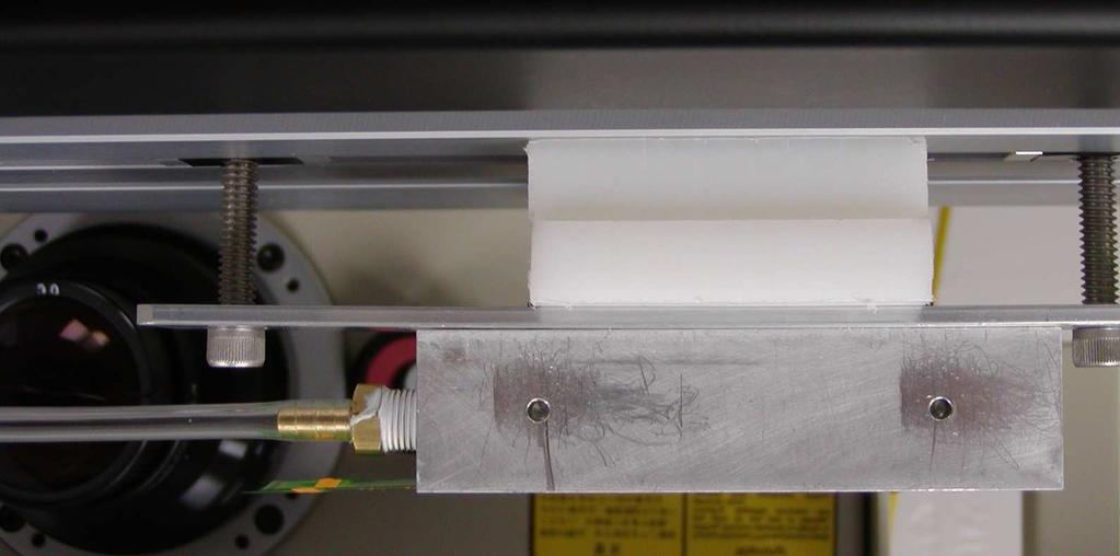
5 Figure 1. Figure 2.
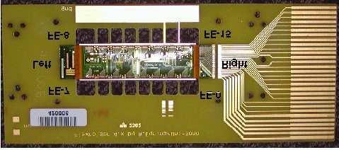
6 Figure 3.
7 4 Lamination of Flex onto FPCB 4.1 Purpose The Frame PCB (FPCB) serves many purposes, including provision of connections for flex hybrid and module test, protection of the bottom solder mask /cover layer and easy handling during flex hybrid and module assembly. Because the FPCB is used in registration of the flex hybrid to the module, the flex must be attached accurately (± 300 µm). The custom laminator provides accurate alignment and an adhesive application and curing system. 4.2 Materials and Equipment No log book is required for this process Laminator Loctite Chipbonder 2614 in caulking gun Bare Flex FPCB Acetone Paper towels Nylon gloves Antistatic zip lock bags Bar code labels Computer access to the PDB Bar code scanner 4.3 Safety Precautions The laminator has components which get hot enough to cause severe burns. Observe where these areas are and avoid contact with them See the material safety sheets for Loctite Chipbonder 3416, on file in the lab Acetone is toxic. See the material safety sheet, on file in the lab. 4.4 Step-by-Step Instructions Connect laminator to house vacuum, if not already connected. Check the vacuum gauge adjacent to the house vacuum service tap for at least 20 mm Hg. If less, check for vacuum leaks or other equipment in use that may be too leaky Turn laminator power on Set Watlow temperature controller on the laminator control panel to 315 o F and allow unit to reach this temperature before proceeding Turn on the vacuum switch on the laminator control panel While wearing nylon gloves, place 5 Compunetics or 3 Dyconex flex on the flex holders, starting from the side where the vacuum enters the flex work holder. Also, the bias hole in the flex is placed toward the FPCB's on the flex work holder. Be sure to mount the flex so that the alignment pins on the flex holders pass through the alignment holes on the flex.
8 4.4.6 Record the measurements in the log book, noting the positions of the measurements by FE number Place 5 FPCB's (even if there are only 3 flex) on the FPCB positions of the laminator, taking care that all three alignment pins mate completely with the corresponding holes in the FPCB's Flip the silk screen over the FPCB's and apply a 1 to 2 inch bead of Loctite Chipbonder 3614 adhesive to one end of the silk screen Using the supplied squeegee, apply an even layer of adhesive to the FPCB's through the silk screen Return the silk screen to the rest position Flip the flex holder bar over the FPCB's and lock into place Press down on the pressure bar until it locks into place Wait one minute Turn off the vacuum switch on the laminator control panel Release the laminator pressure bar Flip the flex holder bar back into the loading position Remove laminated assemblies Inspect the laminated assemblies Attach bar code label and write s/n on flex as described in module serial numbering document Place each FPCB in a zip lock bag When finished, carefully scrape the remaining adhesive from the silk screen using the squeegee. Next, clean the remaining adhesive from the silk screen and other parts of the laminator using acetone and paper towels Enter each flex serial number as category type "FlexOnFrame" into the PDB using the bar code scanner and the web interface to the PDB Storage location TBD. 4.5 Acceptance Criteria Alignment hole in flex shall be aligned to hole in FPCB, as determined by unaided visual inspection The flex tails shall be completely adhered to the FPCB and there should be adhesive under all bond pads There shall be no adhesive on bonding pads or flex The flex shall be flat on the FPCB, as determined by using a gloved finger to apply gentle pressure to the surface of the flex starting at one tail and sliding the finger to the other end. The flex shall remain flat against the FPCB during and at the end of this operation.
9 5 Chemical Cleaning 5.1 Purpose As received from the loading vendor, the flex circuit adheres to the FPCB. This is caused by trapping of solder resin and other contaminants between the flex and the FPCB during automated cleaning at the assembly vendor. The chemical cleaning process removes contaminants from the flex and FPCB. 5.2 Materials and Equipment Log book: CC Loaded flex on FPCB Latex gloves Safety goggles Ultrasonic cleaner Citrasafe Flex holder for cleaning DI water Micro tips / Plastic sticks Propanol Measuring cup Container for rinsing boards Utility sprayer Environmental chamber Zip lock bags Computer access to the PDB Bar code scanner 5.3 Safety Precautions Use gloves to protect hands from Citrasafe and propanol; both can severely dry skin. Use moisturizing hand soap on skin that comes into contact with either Use safety goggles while handling Citrasafe and propanol or propanol + water mix. Flush eyes immediately with running water if exposed. Contact supervisor as soon as possible or seek medical attention See material safety sheet for Citrasafe See material safety sheet for propanol. 5.4 Step-by-Step Instructions Open the window adjacent to the ultrasonic cleaner Clean the Ultrasonic cleaner, micro tips, glass tray, plastic box and the jig (with dish washing detergent, if needed). Rinse with DI water Wash your hands and wear latex gloves Place the flex in the jig slots. Insert the micro tips between the flex and the FPCB so that the flex is held away from the FPCB Fill the ultrasonic cleaner with Citrasafe to the fill line in the tank. Use fresh Citrasafe if the use limit of the used Citrasafe has been reached (TBD.).
10 5.4.6 Place enough DI water and propanol in a 1:1 ratio (using the measuring cup) to cover the FPCB's mounted in the jig Fill the utility sprayer to the fill line with DI water. Pump up the sprayer to operating pressure Place the jig holding the flex circuits in the ultrasonic cleaner. Switch on the ultrasonic cleaner and set the timer for 10 minutes. After 10 min., remove the flex from the ultrasonic cleaner Place the jig in the rinse container and rinse the flex thoroughly in the water + propanol mixture, using manual agitation. Replace the mixture after the prescribed number of uses (TBD) Place the jig in the laboratory sink and spray with DI water from the utility sprayer until the water runs clear. Take care to rinse between the flex and the FPCB thoroughly Remove the flex from the jig and place them on a shelf in the environmental chamber When finished processing a batch or when the environmental chamber is fully loaded, heat chamber to 75 deg. C until flex are dry. Flex will likely dry in different time intervals, so monitoring of drying process is required Place each flex in a zip lock bag when dry Storage location TBD Upload a comment, using the bar code scanner to enter the flex serial numbers for each flex for which the following information is the same (using the batch upload Java applet): "Chemically cleaned" Date Technician name "Logbook CC" + page number 5.5 Cleanup Drain the Citrasafe from the ultrasonic cleaner and store it in the used Citrasafe container Dry the inside of the ultrasonic cleaner tank with a clean paper towel. Cover the ultrasonic cleaner with its lid Clean the rinse container with dish washing detergent and perform the final rinse with DI water. Place it upside down to drip dry Log deviations from this procedure and other observations along with the flex serial numbers in the CC log book Update the PDB comments using the Java application. 5.6 Acceptance Criteria Flex shall not adhere to the FPCB except where attached with adhesive, as described in section Flex and FPCB shall be free of loose debris and contamination Flex and FPCB shall be free of water spots and other discoloration.
11 6 O 2 Plasma Cleaning 6.1 Purpose Plasma cleaning prepares the flex bond pads for wire bonding and improves wire bond pull strength. 6.2 Materials and Equipment Log book: PC Loaded and chemically cleaned flex on FPCB Plasma cleaner with O 2 and N 2 gas supply cylinders 6.3 Safety Precautions The plasma cleaner emits UV radiation during the cleaning process. Be sure to close the outer steel door to block this radiation Oxygen accelerates combustion. Be sure to close the O 2 cylinder valve when cleaning operations are complete Check that the exhaust vent fan is on before beginning operation. The switch is in the machine shop Check the oil level in the vacuum pump before turning it on. 6.4 Step-by-Step Process Open the O 2 and N 2 cylinder valves Turn on the vacuum pump Turn on the exhaust fan and verify its operation Place two chemically cleaned flex on FPCB on each of the three shelves in the plasma cleaner Close the doors and start Program When the program is complete, press the Stop button. The flex are now ready for wire bonding. Handle the FPCB by its edges and be careful not to touch the metal on the flex or the FPCB Don't process another batch until the current batch is used up. Any flex not wire bonded within 24 hr. should be cleaned again using Program 2, just prior to wire bonding Store plasma cleaned flex in the plasma cleaner oven until it is wire bonded Upload a comment, using the bar code scanner to enter the flex serial numbers for each flex for which the following information is the same (using the batch upload Java applet): "Plasma cleaned" Date Technician name "Logbook PC" + page number 6.5 Acceptance Criteria Flex and FPCB metal should be free of visible contaminants.
12 3.1.1 Put a small drop of DI water on an exposed trace on the flex. If it spreads, then it has passed the test. Shake the water off and allow the flex to air dry in the clean room.
13 7 Au Ball Wire Bonding 7.1 Purpose To wire bond the test gap and to wire bond the test pads to the FPCB. 7.2 Safety Precautions The bonding capillary heater is very hot - avoid contact. 7.3 Materials and Equipment Log book: WB Loaded, chemically cleaned and plasma cleaned flex on FPCB Westbond 2000 series bonder configured for Au ball bonding Au ball bonding capillary (specific tools still under evaluation) mil Au bonding wire: % Au % Be % - 5% elongation, On 2" dual flange spool Wire bonder work holder for FPCB Computer access to the PDB Bar code scanner 7.4 Step-by-Step Instructions (Still under development) Open house compressed air valve on back of bonder. Pressure must be 80 PSI ± 20% Open house vacuum. Vacuum pressure must be at least 20 mm Hg Turn on bonder Turn on despooler Turn on external light source Wait for machine initialization to complete Open the Au ball bonding program for the test bonds (check WB log book for current program in use) Verify that the machine is configured for 2700B operation Verify that the tool overdrive is 5 mil Verify that tool heat dial is set at 3.5 (or current setting suggested in WB log book) Place FPCB securely on work holder Pinch red vacuum hose leading to stage once or twice while observing flex circuit. It should visibly be pulled all the way down to the FPCB surface when the hose is released. If not, reposition the FPCB on the work holder and try again Check bond settings on the bonder against latest recommendations in WB log book Start bonding in Pause mode to verify that bonder is working properly. Once satisfied that settings are OK, put bonder in Automatic mode. Observe bonder while in action. Pull failed wires and rebond them.
14 When bonding is complete, check for shorted or missing wires. (During development, record missing, broken and shorted bonds in the log book.) Place FPCB in shipper and secure Plexiglas cover with the four thumb screws Be sure to reverse the procedures of steps when through bonding for the day Storage location TBD Upload a comment, using the bar code scanner to enter the flex serial numbers for each flex for which the following information is the same (using the batch upload Java applet): "Test interface wire bonded" Date Technician name "Logbook WB" + page number 7.5 Acceptance Criteria There shall be no shorted nor missing wire bonds All second bonds shall have a security bond centered on the wedge.
15 8 Wire Bond Potting 8.1 Purpose The wire bonds made in step 7 must be potted to prevent damage from handling during the remaining test and assembly steps, including module assembly and testing. The encapsulant bead is removed with tweezers before the final flex cut is made at each end, taking the wire bonds with it. 8.2 Materials and Equipment Log book: PA EFD fluid dispensing system cc syringe with piston /2" x 20 ga. metal dispensing tip Dow Corning Sylgard 186 potting compound Weight scale Disposable mixing tins Disposable wooden mixing stick 8.3 Safety Precautions Place used tips in an empty plastic bottle. Do not throw tips directly into the trash, as this presents a hazard to the custodial staff See material safety sheet for Sylgard 8.4 Step-by-Step instructions (Manual method - automated method under development.) Weigh out Sylgard resin and hardener in 10:1 ratio in a mixing tin Mix Sylgard thoroughly with wooden stick Pour Sylgard into syringe Place piston in syringe and connect to dispenser air tube. Store syringe in syringe holder when not applying Sylgard Set EFD dispenser in continuous flow mode Lay a few practice beads on a piece of paper to get a feel for the consistency and flow of the Sylgard Use multiple passes to completely cover the wire bonds. Avoid covering the active flex area beyond the bond pads If the process does not meet the acceptance criteria, cure the encapsulant, then remove it with tweezers and wire bond again For rapid curing of the Sylgard, place the FPCB's into the environmental chamber and bake for 30 min. at 100 o C. For room temperature cure, place in N 2 cabinet in the clean room for 48 hours Place FPCB in flex shipper when curing is complete and secure cover with the four thumb nuts Storage location TBD Upload a comment, using the bar code scanner to enter the flex serial numbers for each flex for which the following information is the same (using the batch upload Java applet):
16 "Test interface wire bonds potted" Date Technician name "Logbook PA" + page number 8.5 Acceptance Criteria The encapsulant shall be completely cured with no tackiness There shall be no shorted or broken wire bonds visible under magnification The wire bonds shall be completely covered by the encapsulant The encapsulant shall not contact any components on the flex circuit The encapsulant shall not contact any FE bond pads.
17 9 Envelope Inspection 9.1 Purpose Based on early estimates of the thickness of the sensor, FE's, flex hybrid, adhesive layers and components plus the estimated tolerances, an envelope within which the flex hybrid and components must fit was defined. As we approach production, many of these thicknesses are known to be thinner than originally estimated. As a result, the only inspection that may be necessary is to check that none of the components are misplaced or tombstoned. This is also done at the assembly vendor, so only a sample may need to be checked. However, a procedure has been developed based on the originally tightly constrained envelope definition. This is the procedure which follows and it may be easily adapted in production for less thorough inspections. This procedure does not yet include inspection of the MCC placement and wire bonding, as this procedure is not yet being performed at OU. 9.2 Material and Equipment Log book: EI Loaded flex on FPCB " optical comparator with profile lighting and 10x lens set " vacuum chuck " vacuum FPCB work holder Map of component locations and names Nylon gloves Computer access to the PDB 9.3 Safety Precautions Use nylon gloves when handling flex+fpcb Be very careful not to strike or scratch the optical comparator lense when orienting the FPCB. 9.4 Step-by-Step Procedure Turn "ON" both profile lamp switches on the optical comparator. Connect the 6" vacuum holder to the house vacuum and turn the vacuum valve on Place the vacuum work holder on the vacuum chuck Place a flex on the vacuum work holder. The vacuum can be temparaly released by pinching or crimping the vacuum hose to facilitate positioning the work holder Place the flex facing the lens as shown in Figure 1.

18 Figure 4. Figure 5.

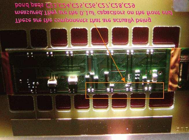
19 Figure Zero the scale of the optical comparator to the top surface of the flex Increase the height of the work bench by mm and check for the tolerance of the capacitors. The capacitors checked are C23, C24, C25, C26, C27, C28 andc29 (Figures 2 & 3). Figure Adjust the focus knob to view components R6, R9, R5, R10, R11, R12, R13 and C22 (Fig. 4) Adjust the bench to the right so that the remaining LDC's (Local Decoupling Capacitors - those that are in line with the FE bond pads on the flex) are visible (Fig. 5).

20 Figure 8.

21 Figure See Figure 6.


22 Figure See Figure See Figure 8. Figure 11.

23 See Figure 9. Figure See Figure 10.

24 Figure 13., See Figure 11.


25 Figure See Figure 12. Figure 15..

26 See Figure 13. Figure See Figure 14. Figure See Figure 15


27 Figure See Figure 16 Figure Record acceptance criteria violations in log book and mark flex as "Failed EI" with label on FPCB (details TBD) Upload test data and result (undefined).
28 9.5.Acceptance Criteria The acceptance criteria are given in the step-by-step instructions In addition, no tombstoned or broken components can be accepted.
COBILT CA-800 Mask Aligner Equipment Operation
 COBILT CA-800 Mask Aligner Equipment Operation For the Micro-Electronics Laboratory At University of Notre Dame Department of Electrical Engineering This user manual is not be removed from room 247A. This
Standard Operating Manual
 Standard Operating Manual AB-M Mask Aligner Version 1.1 Page 1 of 18 Contents 1. Picture and Location 2. Process Capabilities 2.1 Cleanliness Standard 2.2 Wafer Chuck Selection 2.3 Mask Holder Selection
KARL SUSS MJB3 UV400 Mask Aligner Standard Operating Procedure
 KARL SUSS MJB3 UV400 Mask Aligner Standard Operating Procedure Version: 1.0 February 2014 UNIVERSITY OF TEXAS AT ARLINGTON Nanotechnology Research Center (NRC) 1 TABLE OF CONTENTS 1 Introduction 3 1.1
Vacuum Bagging Wings Instruction Manual Purdue University
 Vacuum Bagging Wings Instruction Manual Purdue University Note: Do not leave the vacuum pump running unattended! Revision: Original Release 10/31/15 Vacuum bagged wings are quick to build, light weight,
Syringe, Distribution Valve and Infusion Pump Removal/Replacement ATTENTION SYRINGE REPLACEMENT
 ATTENTION SYRINGE REPLACEMENT Please read through the document completely before starting any repairs. Refer to the proper section in the service manual for complete removal and replacement procedures.
Photolithography. Operating Instructions
 Photolithography Operating Instructions The PR used during this laboratory session will be Microposit S1813 (from Shipley). Make sure everyone is following the laboratory protocol. Wear lab coats, safety
O P E R ATING INSTRUCTIONS FOR MODEL SPR-45 Automatic Screen and Stencil Printer
 O P E R ATING INSTRUCTIONS FOR MODEL SPR-45 Automatic Screen and Stencil Printer TABLE OF CONTENTS I. SPECIFICATIONS...3. II. SAFETY INSTRUCTIONS...4. III. INSTALLATION...5. IV. SET-UP...6. V. SYSTEM OPERATION...9.
Wet Lamination of Dry Film Photoresist for the Hobbyist
 Wet Lamination of Dry Film Photoresist for the Hobbyist By Adam Seychell Updated: 10. September 2009 Table of Contents Introduction...2 Equipment List...3 Squeegee Board...4 The Procedure...5 Cut photoresist
SSI Solaris 150 RTA Revision /27/2016 Page 1 of 9. SSI Solaris 150 RTA
 Page 1 of 9 SSI Solaris 150 RTA The Solaris 150 RTA is a rapid thermal annealing system capable of handling sample sizes up to 100mm (4 diameter) or smaller. The system can anneal in N 2 and Forming gas
Spray Gun 134-A. 1 Liter High- Pressure Gel Coat. Usage Instructions & Parts List
 1 Liter High- Pressure Gel Coat Spray Gun 134-A Usage Instructions & Parts List www.fibreglast.com 1.800.821.3283 385 Carr Drive Brookville, OH 45309 Operating Instructions & Suggestions This is a high
Angstrom E-Beam Instructions. PROCESS CHECKS: the tooling factors of each metal; Ti/Au layer for wire bonding pull test.
 Angstrom E-Beam Instructions Tool Manager: Joe Palmer (jpalmer@princeton.edu) Office: 8-4706; Cell:609-751-1353 Backup: David Barth (dbarth@princeton.edu) Office: 8-4626; Cell: 610-405-8227 PROCESS CHECKS:
OPERATOR S MANUAL Ar-Gone Weld Gas Analyzer
 July 2011 OPERATOR S MANUAL Ar-Gone Weld Gas Analyzer WARNING! Before operating this product, read and understand this Operator s Manual. Become familiar with the potential hazards of this unit. Contact
Napa Technology Trouble Shooting. For Premier & Premier PLUS Models
 Napa Technology Trouble Shooting For Premier & Premier PLUS Models Before contacting Napa Technology for support, please check if the problem and solution are found below: Machine Is Off & All LCD s are
Approved by Principal Investigator Date: Approved by Super User: Date:
 Approved by Principal Investigator Date: Approved by Super User: Date: Standard Operating Procedure BNC OAI 200 Lithographic Mask Aligner (Aligner 3) Version 2011 June 2 I. Purpose This Standard Operating
Equipment Standard Operating Procedure Greg Allion and Kimberly Appel
 Date Created: May 3, 2004 Date Modified: June 1, 2005 MA6/BA6 Mask Aligner Equipment Standard Operating Procedure Greg Allion and Kimberly Appel 1. Purpose 1.1. Photolithography involves transferring a
OPERATION MANUAL Please read this Operation Manual carefully before use, and file for future reference.
 English Lubrication Free Air Turbine Handpiece with Water Spray OPERATION MANUAL Please read this Operation Manual carefully before use, and file for future reference. OM-T0286E 001 Thank you for purchasing
Operating Procedures for Metal Evaporator I
 Operating Procedures for Metal Evaporator I Metal Evaporator I is intended as a tool and a training device. Understanding the operation of this equipment should give you a basic knowledge of vacuum and
KARL SUSS MJB3 MASK ALIGNER STANDARD OPERATING PROCEDURE
 KARL SUSS MJB3 MASK ALIGNER STANDARD OPERATING PROCEDURE Purpose of this Instrument: This instrument is for patterning photosensitive polymers with UV light. Location: White Hall 410 Cleanroom Primary
The Outer Seal is highly abrasion resistant and provides mechanical stiffness to the splice in order to better match the cable stiffness.
 The Sealing Compound encapsulates the electrical splices, provides a strain relief for the conductors, acts as a water block, eliminates air voids which tend to act as pumps to draw in water during pressure
REL-46 WARNING NOTICE 15 TON SINGLE ACTING REMOTE HYDRAULIC CRIMPING HEAD. Compatible with RELIABLE R15 and P Style dies. REL-46 Manual
 OPERATORS ORS GUIDE REL-46 15 TON SINGLE ACTING REMOTE HYDRAULIC CRIMPING HEAD Compatible with RELIABLE R15 and P Style dies. RELIABLE EQUIPMENT & SERVICE CO., INC. 301 Ivyland Road Warminster, PA 18974
JETFIRST 150 RTA SYSTEM OPERATING MANUAL Version: 2 Feb 2012
 JETFIRST 150 RTA SYSTEM OPERATING MANUAL Version: 2 Feb 2012 UNIVERSITY OF TEXAS AT ARLINGTON Nanofabrication Research and Teaching Facility TABLE OF CONTENTS 1. Introduction....2 1.1 Scope of Work.....2
PDY TON HYDRAULIC CRIMPING TOOL WARNING
 OPERATORS ORS GUIDE PDY-1220 12 TON HYDRAULIC CRIMPING TOOL All information found in this guide must be read and understood before use or testing of this tool. Failure to read and understand these warnings
SUMMITTM 400 & 600. Natural Gas Barbecues. Step-By-Step Guide
 SUMMITTM 400 & 600 Natural Gas Barbecues Step-By-Step Guide W E B E R W E B E R W E B E R W E B E R Summit 400 NG Summit 600 NG CANADIAN GAS ASSOCIATION R A P P R O V E D WARNING: Follow all leak check
OPERATION MANUAL BFX-2
 OPERATION MANUAL BFX-2 Brake Fluid Exchanger IMPORTANT Test drive vehicle after service to verify proper brake system performance. MAHLE Aftermarket Inc., Service Solutions 10 Innovation Drive York, PA
OAI Model 200 Tabletop Mask Aligner Portland State University
 OAI Model 200 Tabletop Mask Aligner Portland State University WARNING: This machine exposes users to ultraviolet radiation. Do not touch the lens underneath the lamp hood as it may damage the machine and
REL-510H WARNING NOTICE 12 TON SINGLE ACTING REMOTE HYDRAULIC CRIMPING HEAD
 OPERATORS ORS GUIDE REL-510H 12 TON SINGLE ACTING REMOTE HYDRAULIC CRIMPING HEAD Compatible with U style and RELIABLE R12 shell type 12 ton compression dies. RELIABLE EQUIPMENT & SERVICE CO., INC. 92 Steamwhistle
Instruction Manual Otoflash G171 UV-flash-device for Light Curing
 Instruction Manual Otoflash G171 UV-flash-device for Light Curing Index 1) General Information 2) Initial Operation of Device 3) Important Notes 4) Use with timer 5) Exchanging the flash module 6) Maintenance,
PURDUE UNIVERSITY TEFLON CORE PCB THRU-HOLE PREPARATION FOR BLACK HOLE APPLICATION RF LAB. Professor in charge: William Chappell MSEE 289
 RF LAB Professor in charge: William Chappell MSEE 289 AUTHOR: BOB SALISBURY DATE: 12/5/2007 12/6/2007 page 1 of 7 TABLE OF CONTENTS 1 SCOPE... 3 2 PURPOSE... 3 3 REFERENCE DOCUMENTS... 3 4 MATERIALS...
MJB4 Mask Aligner Operating Procedure. Effective Date: 07/12/2012 Author(s): Jiong Hua Phone:
: Jiong Hua Phone:") MJB4 Mask Aligner Operating Procedure Effective Date: 07/12/2012 Author(s): Jiong Hua Phone: 402-472-3773 Email: jhua2@unl.edu 1 1 Introduction 1.1 Key Words Karl Suss MJB4 Mask Aligner, Optical Lithography,
MJB4 Mask Aligner Operating Procedure Effective Date: 07/12/2012 Author(s): Jiong Hua Phone: 402-472-3773 Email: jhua2@unl.edu 1 1 Introduction 1.1 Key Words Karl Suss MJB4 Mask Aligner, Optical Lithography,
2 Switching off ECRIS 3. 4 Acquire Beam Spectrum 4. 6 Vent Instrument Chamber 5. 7 Pump down Chamber 5. 8 Baking out Chamber 5.
 Contents 1 Starting the ECR ion source (ECRIS) 2 2 Switching off ECRIS 3 3 Starting Mefisto Beam Analyzer 4 4 Acquire Beam Spectrum 4 5 Open Valve ECRIS/Chamber (Gate valve) 4 6 Vent Instrument Chamber
Inspection and Acceptance of Asphalt Mix Design Laboratories
 Supplemental Technical Specification for Inspection and Acceptance of Asphalt Mix Design Laboratories SCDOT Designation: SC-M-405 (05/1/14) 1. SCOPE 1.1 This specification covers the process for inspection
1.1 Equipment: substrate, wafer tweezers, metal targets 1.2 Personal Protective Equipment: nitrile gloves, safety glasses 1.
 Nanomaster NSC-3000 DC Magnetron Sputter Tool Standard Operating Procedure Faculty Supervisor: Prof. Robert White, Mechanical Engineering (x72210) Safety Office: Peter Nowak x73246 (Just dial this directly
5.1.3 Mechanical Hazards Drive assemblies have sufficient power to cause injury. Keep hands, fingers, clothing and tools clear of moving parts.
 Approved by: Process Engineer / / / / Equipment Engineer 1 SCOPE The purpose of this document is to detail the use of the PE4400. All users are expected to have read and understood this document. It is
Superconducting Susceptometer (MPMS-5S) Quantum Design Room 296 (MPMS)
 Quantum Design Room 296 (MPMS)") Superconducting Susceptometer (MPMS-5S) Quantum Design Room 296 (MPMS) Sensitivity: 1x10 11 A m 2 Applied DC fields: 0 T to 5 T Applied AC fields: 0 G to 3 G (zero-to-peak), 0.01 Hz to 1000 Hz Temperatures
Superconducting Susceptometer (MPMS-5S) Quantum Design Room 296 (MPMS) Sensitivity: 1x10 11 A m 2 Applied DC fields: 0 T to 5 T Applied AC fields: 0 G to 3 G (zero-to-peak), 0.01 Hz to 1000 Hz Temperatures
Warnings: Notes: Revised: January 8,
 OAI Model 204IR Mask Aligner Standard Operating Procedure Faculty Supervisor: Prof. Robert White, Mechanical Engineering (x72210) Safety Office: Peter Nowak x73246 (Just dial this directly on any campus
Inspection and Approval of Asphalt Mix Design Laboratories
 Supplemental Technical Specification for Inspection and Approval of Asphalt Mix Design Laboratories SCDOT Designation: SC-M-405 (06/07) 1. SCOPE 1.1 This method covers the process for inspection and approval
BASIC Z-STACK AND TIME SERIES SCAN ON THE ZEISS LIGHTSHEET Z. 1
 BASIC Z-STACK AND TIME SERIES SCAN ON THE ZEISS LIGHTSHEET Z. 1 The front door of the main body of the instrument may be open when you arrive. Take the sample chamber and slide it into position with the
Procedure 85 Attaching The Humidifier To The Oxygen Flow Meter Or Regulator. Procedure 86 Administering Oxygen Through A Nasal Cannula
 Chapter 12 Respiratory Procedures Procedure 81 Checking Capillary Refill Procedure 82 Using A Pulse Oximeter Procedure 83 Preparing Wall-Outlet Oxygen Procedure 84 Preparing The Oxygen Cylinder Procedure
EASTERN ENERGY SERVICES PTE LTD. 60 Kaki Bukit Place #02-19 Eunos Tech Park Singapore, SG Singapore Telephone: Fax:
 2 Table Of Contents 1. Introduction 3 2. About this Manual 3 3. Contacting YZ Systems 3 4. Vessel Components 4 5. Specifications 5 6. Application 6 7. Theory of Operation 7 8. DuraSite Installation & Use
Misaligned Folds Paper Feed Problems Double Feeds Won t Feed FLYER Won t Run iii
 Operator s Manual Table of Contents Operator Safety... 1 Introduction... 2 Unpacking and Setup... 3 Unpacking... 3 Setup... 4 FLYER Overview... 5 FLYER Diagram... 5 Capabilities... 5 Control Panel... 6
Approved by Principal Investigator Date: Approved by Super User: Date:
 Approved by Principal Investigator Date: Approved by Super User: Date: Standard Operating Procedure BNC OAI Lithographic Mask Aligner (Aligner 2) Version 2008 October 31 I. Purpose This Standard Operating
Instructions for Assembly, Installation, and Operation of the Gas Addition Kit Accessory with the CEM Discover Systems
 Corporation Issued: 5/09 P/N: 600104 Rev. 2 Instructions for Assembly, Installation, and Operation of the Gas Addition Kit Accessory with the CEM Discover Systems The Gas Addition Accessory permits the
Instruction Manual LIMITED 1 YEAR WARRANTY. Hydraulic Punch Driver Read this material before using this product.
 Instruction Manual Hydraulic Punch Driver 902-483 LIMITED 1 YEAR WARRANTY We make every effort to assure that its products meet high quality and durability standards, and warrant to the original purchaser
PROPORTIONING VALVE. Model 150 INSTRUCTION MANUAL. March 2017 IMS Company Stafford Road
 PROPORTIONING VALVE Model 150 INSTRUCTION MANUAL March 2017 IMS Company 10373 Stafford Road Telephone: (440) 543-1615 Fax: (440) 543-1069 Email: sales@imscompany.com 1 Introduction IMS Company reserves
SOP for Karl Suss MJB3 #1 Mask Aligner
 SOP for Karl Suss MJB3 #1 Mask Aligner Rev. 5 (30/11/2016) Safety UV Exposure: The high-energy light produced by the high-pressure Mercury Xenon lamp can cause eye damage and skin burns. Be sure that the
Basic & Controlled Atmosphere Glove Boxes
 I N T R O D U C T I O N Precise Basic and Controlled Atmosphere Glove Boxes provide a leak-tight environment for work with contamination-sensitive materials. Precise Basic Glove Boxes are simple, economical
Approved by Principal Investigator Date: Approved by Super User: Date:
 Approved by Principal Investigator Date: Approved by Super User: Date: Standard Operating Procedure BNC Commonwealth Dual Ion Beam Deposition System (CDIBS) Version 2010 February 14 I. Purpose This Standard
Standard Operating Manual
 Standard Operating Manual Fisher Scientific Isotemp TM Model 281A Vacuum Oven Version 1.1 Page 1 of 9 Contents 1. Picture and Location 2. Process Capabilities 2.1 Cleanliness Standard 2.2 Substrate Size
RH800 & 2000 BASIC OPERATIONS
 RH800 & 2000 BASIC OPERATIONS 2 General information This manual contains technical information regarding Bayer SeedGrowth Equipment. Please read and understand these instructions completely before proceeding
MODEL 1329 Tank Gauge
 SERVICE INSTRUCTIONS FOR PETRO-METER 1329 GAUGE SERVICE INSTRUCTIONS MODEL 1329 Tank Gauge www.petro-meter.com Petro-Meter 1329 series Service Instructions HOW TO DETERMINE IF A PETRO-METER IS IN GOOD
ShellPa. Standard Mechanical Cell Stretch System Model No: NNMS Serial #: User Manual
 ShellPa Standard Mechanical Cell Stretch System Model No: NNMS Serial #: User Manual To operate the system properly and safely, read the manual before using ShellPa. This system is not a medical device.
LAB Chip Lid Molding LAB PROCEDURE
 LAB Chip Lid Molding LAB PROCEDURE The purpose of this lab is to expose the student to a lab-on-a-chip fabrication technique. The student will utilize polydimethylsiloxane (PDMS) poured in four Petri dishes
AGM 33 PIKE ALL FIBERGLASS. Specifications Length: 92 Diameter 5.5 Weight: 24 lbs Motor Mount: 75mm Fins: 6-3/16 G10 CP: 68 from nose tip Parts List
 ALL FIBERGLASS AGM 33 PIKE Specifications Length: 92 Diameter 5.5 Weight: 24 lbs Motor Mount: 75mm Fins: 6-3/16 G10 CP: 68 from nose tip Parts List (1) Filament Wound Nose Cone w/ Metal Tip (1) Nose Cone
Underwater Housing for Canon EOS M
 Underwater Housing for Canon EOS M User Manual 1 Table of Contents 1. Introduction 2. Specifications 3. Function Controls 4. Set up Instructions 5. Use & Care of Housing 6. Service 7. Warranty 1. Introduction
Installation of Your SprayMaster System
 Installation of Your SprayMaster System 1. At the installation site, remove all equipment from the corrugated box and the polyethylene drum and replace the drum lid. Check the picture to identify each
Supplementary Operation, Assembly, Maintenance Manual for F3-42 model and optional attachments
 FERMENATOR TM Supplementary Operation, Assembly, Maintenance Manual for F3-42 model and optional attachments Congratulations on your purchase, and thank you for selecting the Fermenator TM stainless conical
PremAire INSTRUCTIONS FOR VORTEX TUBE MODE OF OPERATION
 DUAL SUPPLY REGULATOR ESCAPE CYLINDER VORTEX MAIN INLET PremAire INSTRUCTIONS FOR VORTEX TUBE MODE OF OPERATION WARNING THIS MANUAL MUST BE READ CAREFULLY BY ALL PERSONS WHO HAVE OR WILL HAVE THE RESPONSIBILITY
TABLE OF CONTENTS SAFETY FIRST!...3 BASIC OPERATION...4 ADJUSTMENTS...5. Cocking Pressure...5. Three-Way Valve Adjustment...6
 TABLE OF CONTENTS SAFETY FIRST!...3 BASIC OPERATION...4 ADJUSTMENTS...5 Cocking Pressure...5 Three-Way Valve Adjustment...6 External Three-Way adjustment...6 In-Line Regulator...6 Ram to Cocking Block
DEH Instructions. Three-Phase, Platform-Mounted Distribution Transformers
 g DEH 40050 Instructions Three-Phase, Platform-Mounted Distribution Transformers Introduction The equipment covered by these instructions should be operated and serviced only by competent technicians familiar
Title: Xactix XeF2 Etcher Semiconductor & Microsystems Fabrication Laboratory Revision: A Rev Date: 03/23/2016
 Approved by: Process Engineer / / / / Equipment Engineer 1 SCOPE The purpose of this document is to detail the use of the Xactix XeF2 Etcher. All users are expected to have read and understood this document.
To be used as a coating for potable water tanks and pipes. Independently tested and certified for potable water storage. Other
 Approved 31462;9441 1,2 31462 epoxy ^(ValidationDate) 1 Product description This is a two component solvent free amine cured epoxy coating. It is specially designed for drinking water tanks. Can be used
Glove Box Installation Manual
 Glove Box Installation Manual 1998 by M. Braun Company File: GB-UNI-INS.DOC! Edition 08-00 by M. Boutin! Subject to be changed without notice Glovebox Installation Your Glove box has been fully assembled,
TJF-Q180V Cleaning and Disinfection Checklist
 TJF-Q180V Cleaning and Disinfection Checklist TJF-Q180V Cleaning and Disinfection Checklist This checklist is used to evaluate and confirm if cleaning and disinfection of the TJF-Q180V has been performed
LUBRICATOR ASSEMBLY AND OPERATING INSTRUCTIONS
 AIR FILTER, REGULATOR AND LUBRICATOR 4035 ASSEMBLY AND OPERATING INSTRUCTIONS 349 Mission Oaks Blvd., Camarillo, CA 930 Visit our Web site at http://www.harborfreight.com Copyright 004 by Harbor Freight
Our technical information is based on Tip: calls attention to special information.
 SUPPLY TANKS (CBP) 2 General information This manual contains technical information regarding Bayer SeedGrowth Equipment. Please read and understand these instructions completely before proceeding to install
MJB-3 Mask Aligner Property of TAU MNCF August 2012
 MJB-3 Mask Aligner I. Power Up Sequence 1 LOG IN. Turn on Nitrogen & compressed air lines on the back wall. 2 Turn on the vacuum pump. 3 Flip the COMPRESSED AIR toggle on (up) Compressed air is used to
NOVALYNX CORPORATION MODEL RAIN GAUGE CALIBRATOR INSTRUCTION MANUAL
 NOVALYNX CORPORATION MODEL 260-2595 RAIN GAUGE CALIBRATOR INSTRUCTION MANUAL REVISION DATE: August 2018 Receiving and Unpacking Carefully unpack all components and compare to the packing list. Notify NovaLynx
1. Safety glasses are to be worn at all times in the laboratory except in the study area adjacent to the lab.
 SAFETY RULES page 1 General Precautions 1. Safety glasses are to be worn at all times in the laboratory except in the study area adjacent to the lab. 2. No horseplay. This includes running, throwing of
PRESSURISED PAINT CONTAINER
 PRESSURISED PAINT CONTAINER MODEL NO: CPP2B PART NO: 3082115 OPERATION & MAINTENANCE INSTRUCTIONS GC0913 INTRODUCTION Thank you for purchasing this CLARKE Pressurised Paint Container. Before attempting
NRF Suss Delta 80 Spinner SOP Revision /14/2016 Page 1 of 11. Suss Delta 80 Spinner SOP
 Page 1 of 11 Note: latest updates are blue. Table of Contents Suss Delta 80 Spinner SOP 1.0 Safety 2.0 Quality Controls and Calibration 3.0 Equipment Uses and Restrictions 4.0 Equipment Specifications
Standard Operating Manual
 Standard Operating Manual Denton Explorer 14 RF/DC Sputter Version 1.0 Page 1 of 11 Contents 1. Picture and Location 2. Process Capabilities 1. Cleanliness Standard 2. Available for Sputtering Materials
User Manual for the Mars Calibration Bench
 User Manual for the Mars Calibration Bench Fall 2013 Table of Contents Table of Contents Table of Contents... iii Introduction... v Chapter 1: The Mars Calibration Bench... 1 What Is the Mars Calibration
INSTALLATION & MAINTENANCE INSTRUCTION
 ARCHON Industries, Inc Liquid Level Gauges Models: BT-LLG ND-LLG INSTALLATION & MAINTENANCE INSTRUCTION Instruction No.: 1014.2 Revision Issued: 3/01/03 Approved: Engineering Manager Warning ONLY QUALIFIED
product manual HM-4140, HM-4150, HM-4160 HM-4160A HM-4150 Humboldt FlexPanels
 12.09 product manual HM-4140, HM-4150, HM-4160 HM-4160A HM-4150 Humboldt FlexPanels Introduction: This manual covers the installation and operation of Humboldt FlexPanels for Triaxial and Permeability
Model 130M Pneumatic Controller
 Instruction MI 017-450 May 1978 Model 130M Pneumatic Controller Installation and Operation Manual Control Unit Controller Model 130M Controller is a pneumatic, shelf-mounted instrument with a separate
RADIATION PROCEDURES MANUAL Procedure Cover Sheet
 RADIATION PROCEDURES MANUAL Procedure Cover Sheet Procedure Title: Calibration of Eberline Portable Particulate Noble Gas Monitor Procedure Number: TSO-08-13-REV 1 Effective Date: July 1, 2008 Approved
PRO SINK -R 1 and 2. Dilution system CONTENTS
 PRO SINK -R 1 and 2 Dilution system CONTENTS 1.0 Product description 2 2.0 Warnings.. 3 3.0 Installation procedure 4 4.0 Plumbing connections 4 5.0 Technical features.. 5 6.0 Maintenance... 6 7.0 Troubleshooting......6
3M DICHROIC Glass Finishes
 3M DICHROIC Glass Finishes DF-PA DF-PA Chill Chill & & DF-PA DF-PA Blaze Blaze Doc TypeInstallation Product #Guide (opt.) Revision D, April 2018 Product Description 3M DICHROIC Glass Finish DF-PA (the
SAFETY Always wear approved safety goggles or an approved mask whenever you handle this paintball marker!
 Instruction Manual Table of Contents SAFETY... 1 COMPRESSED AIR ONLY... 2 FAST START... 3 FIRST TIME PROBLEMS... 4 PERFORMANCE... 4 LUBRICATION... 5 VELOCITY ADJUSTMENT... 5 CLEANING... 5 PAINTBALLS...
Equipment Operating Procedure Glove Box
 Equipment Operating Procedure Glove Box Page 1 0.0 Changing the Compressed Gas Cylinder 1. Complete Compressed Gas Cylinder training from EHS website before manually exchanging gas cylinders. In order
Notes Before Use...2 Notes on charging your watch...2. Your Watch...4 Name of Components...6 About the crown...7
 Table of Contents Notes Before Use...2 Notes on charging your watch...2 Your Watch...4 Name of Components...6 About the crown...7 Setting the Time and Calendar...8 1) Setting the time and day...8 2) Setting
Hydraulic Punch Drivers
 SERVICE MANUAL 7804SB / 7806SB Quick Draw 7704SB / 7706SB Quick Draw Flex Quick Draw Hydraulic Punch Drivers Serial Codes AHJ and YZ Read and understand all of the instructions and safety information in
WSN: XXXXXX 101 ROME COURT FORT COLLINS, CO, PHONE #: (970) FAX #: (970) TO-Clean Manual
 FAX #: (970) TO-Clean Manual") WSN: XXXXXX 101 ROME COURT FORT COLLINS, CO, 80524 PHONE #: (970) 221-9179 FAX #: (970) 221-9364 TO-Clean Manual Copyright 2008 by Wasson ECE Instrumentation, Inc. (SJC 02/05/2008) All rights reserved
WSN: XXXXXX 101 ROME COURT FORT COLLINS, CO, 80524 PHONE #: (970) 221-9179 FAX #: (970) 221-9364 TO-Clean Manual Copyright 2008 by Wasson ECE Instrumentation, Inc. (SJC 02/05/2008) All rights reserved
FAULT CODE TROUBLESHOOTING INDEX
 FAULT CODE TROUBLESHOOTING INDEX 1. Display indicates Change Filters 2. Display indicates Drip Tray Full Continuous Alarm will Sound 3. Display indicates Cold Fault 4. Display indicates Hot Fault 5. Display
Contents. Stainless Steel Side Block. 1.1 Separating the Side Block. Stainless Steel Side Block Reassembly of. Assembly from the Helmet Shell
 Separating the Side Block Assembly from the Helmet Shell Contents SSB-1 SSB-3 SSB-5 SSB-5 SSB-7 1.1 Separating the Side Block Assembly from the Helmet Shell 1.2 Side Block Assembly Replacement 1.3 Defogger
Karl Suss MJB4 Mask Aligner
 Karl Suss MJB4 Mask Aligner Tool Manager: Yong Sun ( yongs@princeton.edu; Office 8-8234; Cell 609-917-5076 ) Backup: George Watson ( gwatson@princeton.edu; Office 8-4626; Cell 732-996-2713 ) ******************************************************************************
Santa Fe Cycles Assembly Guide Introduction
 Santa Fe Cycles Assembly Guide Introduction Congratulations on your purchase of your new Santa Fe bicycle. You have purchased a bicycle that has many features and qualities. Please take a few minutes and
To be used as a coating for potable water tanks and pipes. Independently tested and certified for potable water storage. Other
 Approved 9440;9441 1,2 9440 epoxy ^(ValidationDate) 1 Product description This is a two component solvent free amine cured epoxy coating. It is specially designed for drinking water tanks. Can be used
Hercules Space Saver Sole Press series
 Hercules Space Saver Sole Press series HERCULESSSD Also available in single, SKU: HERCULESSS Operator Manual Manufactured by: 2 HERCULES SPACE SAVER PRESS GENERAL DESCRIPTION Your Hercules Press is designed
Lesson 6: Flow Control Valves
 : Flow Control Valves Basic Hydraulic Systems Hydraulic Fluids Hydraulic Tank Hydraulic Pumps and Motors Pressure Control Valves Directional Control Valves Flow Control Valves Cylinders : Flow Control
Instruction Manual Updated 7/26/2011 Ver. 2.2
 4-Unit Model MB HTHP Filter Press #171-50-4: 115-Volt #171-51-4: 230-Volt Instruction Manual Updated 7/26/2011 Ver. 2.2 OFI Testing Equipment, Inc. 11302 Steeplecrest Dr. Houston, Texas 77065 U.S.A. Tele:
REVISION LIST CHAPTER 8: OUTBOARD WING SECTION CLOSING
 REVISION LIST CHAPTER 8: The following list of revisions will allow you to update the Legacy construction manual chapter listed above. Under the Action column, R&R directs you to remove and replace the
FOR SAFE AND CORRECT USE
 FOREWARD Thank you for purchasing the Model AP-20 sampling pump. The Model AP-20 pump is designed specifically for use with Kitagawa detector tubes. This system with the available Kitagawa detector tubes
OPERATION OF THE DIMPLER
 OPERATION OF THE DIMPLER After thinning your sample to ~80 μm you can now do a dimpling process to thin the center up to 10 μm. When you walk in and use the DIMPLER it should already be calibrated and
ALERT SERVICE LETTER
 Citation TITLE ALERT SERVICE LETTER ASL750-35-04 OXYGEN - TRANSMITTAL OF AVOX SYSTEMS SERVICE INSTRUCTION 833-35-01 REVISION D, REPACKING PROCEDURES FOR 289 PASSENGER OXYGEN MASKS EFFECTIVITY MODEL SERIAL
35 TON HYDRAULIC PUNCH WARNING
 OPERATORS GUIDE REL-35T-PNC 35 TON HYDRAULIC PUNCH NOTICE Sizes, weights and tool specifications listed in this manual are subject to change without notice. Please consult factory for information and updates.
SPUTTER STATION STANDARD OPERATING PROCEDURE
 SPUTTER STATION STANDARD OPERATING PROCEDURE Purpose of this Instrument: This instrument is used for deposition of thin metal or oxide films. Source materials supplied by WVU Shared Research Facilities:
R I T. Title: Amray 1830 SEM Semiconductor & Microsystems Fabrication Laboratory Revision: A Rev Date: 09/29/03 1 SCOPE 2 REFERENCE DOCUMENTS
 Fabrication Laboratory Revision: A Rev Date: 09/29/03 Approved by: Process Engineer / / / / Equipment Engineer 1 SCOPE The purpose of this document is to detail the use of the Amray 1830 SEM. All users
Tridak Model 1050 User Guide
 Tridak Model 1050 User Guide Syringe Filling System Instructions for Safe Use Setup and Operation Maintenance Ordering Spare Parts and Accessories 2 Tridak Model 1050 Syringe Filling System User Guide
4 ft General Solvent Hood Operations
 4 ft General Solvent Hood Operations Roger Robbins 2/13/2006 C:\\MyDocuments\CleanRoomGeneral\Equipment\Hoods\Solvent4ft\4ftGenSolvHood.doc THE UNIVERSITY OF TEXAS AT DALLAS ERIK JONSSON SCHOOL OF ENGINEERING