TANKS AND EQUIPMENT FOR LIQUEFIED PETROLEUM GASES - STORAGE AND SERVICE STATIC TANKS VAPORIZATION SYSTEMS AUTO GAS SKIDS TANK CONTAINERS
|
|
|
- Dortha Blair
- 5 years ago
- Views:
Transcription

1 TANKS AND EQUIPMENT FOR LIQUEFIED PETROLEUM GASES - STORAGE AND SERVICE STATIC TANKS VAPORIZATION SYSTEMS AUTO GAS SKIDS TANK CONTAINERS TANKERS FOR TRANSPORT

2 since 1964 guarantee of quality


3 TANKS Engineering, development and manufacture of tanks for your liquefi ed petroleum gas projects Solutions


4


5 INDEX PAGE STATIC TANKS Horizontal aboveground tanks Horizontal underground tanks Vertical aboveground tanks ACCESSORIES FOR TANKS Valve equipment Cathodic protection Covers and inspection chambers /anchor slabs /booths for cylinders TECHNICAL INFORMATION Foundations and pits Natural vaporization tables LPG fi lling. Maximum degree of fi lling Tanks for ammonia VAPORIZATION SYSTEMS Tanks with internal vaporizer Tanks with atmospheric vaporizer FEED OUT vaporizers Modular vaporization equipment Modular heating equipment AUTOGAS SKIDS Horizontal aboveground SKID Vertical aboveground SKID Underground SKID TANK CONTAINERS Tank containers TANKERS FOR TRANSPORT OF LPG Tankers for transport of LPG Semi-trailer tankers for transport of: LT42 - LT Semi-trailer tankers for transport and distribution of LPG: LTT42 - LTT

6 STATIC TANKS Horizontal aboveground tanks Horizontal underground tanks Vertical aboveground tanks Static tanks for the storage of LPG in aboveground and underground installations, made in accordance with European Directive 2014/68/UE and with CE marking. Upon request we can manufacture tanks to the regulatory requirements of the place of destination. Optionally any tank capacity can be manufactured in accordance with ASME VIII div. 1 and ASME marking. CAPACITIES: capacities from 1 to 400 m 3. Thanks to our extensive range of diameters, the scope of possible tank sizes always allows storage capacity requirements to adapt to the characteristics of each project. STORED PRODUCT AND DESIGN PRESSURE: The information in this catalogue refers to storage of LPG at a design pressure of 20 bar. For other products of similar characteristics or other pressures, please consult us. FINISHES: External tank protection with fi nishes that are highly resistant to corrosion, both for aboveground and underground installations. Standard finish: Shot-blasting of the whole of the outer surface of the tank, application of high protection capacity epoxy-polyamide primer and top coat of white or black polyurethane depending on whether the tank is installed aboveground or underground. Special finishes: thick coat fi nish for underground tanks, highly resistant to impacts and with dielectric strength certifi cation (up to V). Special finishes at customer s request: Special fi nishes according to our customer s specifi cations and/or project requirements. VALVES: Tanks with capacities < 20 m 3 include the standard valve sets in the supply. For tanks with capacities greater than 20 m 3, the valve equipment is listed in this catalogue (page 16). CATHODIC PROTECTION: Cathodic protection equipment comprising sacrifi cial anodes (optionally with bag of activating mix), wiring and connection terminals, dimensioned for each of the tank models for underground installation. OPTIONS: Centred connections: All models can have the centred outlets option (which can be useful when establishing safety distances for installation). Valves mounted: the tank can be supplied with the valve equipment mounted, with valves tightness test and tank inerted with nitrogen. Tanks with anchor slab: Sets of tank-concrete anchor slab for capacities of up to litres. 6


7 7
8 HORIZONTAL ABOVEGROUND/UNDERGROUND, 1.000, 1.200, and mm diam. Rectangular inspection chamber with cover for underground tanks >14 m3 (in stainless steel for less than 20 m3) Round stainless steel inspection chamber with cover for underground tanks <14 m3 (*) Reversible cover for aboveground tanks (Fire resistance B-s3d0 according to/en ) Distribution of outlets and connections EXTERNAL PROTECTION: Shot-blasting to SA 2-1/2 Anti-corrosion primer Polyurethane finish Supports for Ø and Supports for Ø and Earth connection Ø 12 hole Ø 20 (*) Models LP11E and LP13E-17 include a rectangular inspection chamber Ø 30 Data (shown in the table), valid for aboveground and underground tanks. Outlets and valves: see page 15. Rated capacity (litres) Model Ref. Approx. empty weight (Kg) Stored propane (Kg) Total area (m²) CHARACTERISTICS TABLE Minimum discharge of safety valve (m³/min. air) Abovegrd. Undergrd Dimensions (mm) D A B G G1 I J K 990 LP1000* ,2 41,2 28, LP1450* ,7 50,7 35, LP1825* ,9 58,0 40, LP2250* ,3 66,3 46, LP2450* ,1 71,0 49, LP2670* ,9 75,6 52, LP4000* ,3 99,8 69, LP4440* ,8 107,7 75, LP4660* ,6 111,9 78, LP4880* ,4 116,1 81, LP6430* ,5 141,9 99, LP6650* ,3 145,8 102, LP6870* ,1 149,7 104, LP7090* ,9 153,6 107, LP8334* ,3 174,7 122, LP4950* ,1 104,0 72, LP7000* ,7 132,9 93, LP10* ,9 172,8 121, LP13* ,1 210,8 147, LP16* ,2 246,9 172, LP19* ,4 282,3 197, LP22* ,6 316,8 221, LP11* ,6 166,6 116, LP13* ,0 192,0 134, LP15* ,3 216,3 151, LP20* ,0 263,5 184, LP24* ,6 308,5 215, LP29* ,3 352,4 246, LP34* ,0 395,3 276, LP38* ,6 436,7 305, *=A: for aboveground tanks- *=E: for underground tanks - G1: dimension for option <centred outlets> 8
9 HORIZONTAL ABOVEGROUND, and mm diameters (greater than 20 m 3 ) DN 420 manhole and magnetic level High point and pressure gauge 3/4 NPT Safety valve manifold flange ASA 4" 300# Rotating level 1 NPT (>60 m3) Drain 1-1/4 NPT Thermometer thermowell 1/2 NPT (>60 m3) Filling 2 NPT Gas phase 2 NPT Liquid phase 2 NPT Support strip Earth connection M12 EXTERNAL PROTECTION: Shot-blasting to SA 2-1/2 Anti-corrosion primer White finish These models have support strips and can be placed directly on a concrete cradle (see page 22). CHARACTERISTICS TABLE Rated capacity (litres) Model Ref. Approx. empty weight (Kg) Stored propane (Kg) Total area (m²) Minimum discharge of safety valve (m³/min. air) Dimensions (mm) D A B G H L LP23A ,4 256, LP26A ,5 282, LP28A ,6 295, LP30A ,7 308, LP33A ,8 334, LP36A ,0 359, LP38A ,0 371, LP40A ,1 383, LP43A ,3 408, LP46A ,4 432, LP48A ,5 444, LP50A ,6 455, LP53A ,7 479, LP56A ,9 502, LP58A ,0 514, LP59A ,0 525, LP63A ,2 548, LP66A ,3 570, LP68A ,4 581, LP69A ,5 593, LP73A ,6 615, LP76A ,8 637, LP78A ,9 648, LP79A ,9 658, LP23A ,7 240, LP25A ,5 257, LP27A ,3 273, LP32A ,9 305, LP36A ,5 337, LP39A ,3 352, LP41A ,1 367, LP46A ,8 398, LP50A ,4 428, LP52A ,2 442, LP55A ,0 457, LP59A ,6 486, LP64A ,2 514, LP66A ,1 529, LP68A ,9 543, LP73A ,5 571, LP77A ,1 598, LP80A ,9 612, LP82A ,7 626, LP87A ,4 653, LP91A ,0 680, LP93A ,8 693, LP96A ,6 706, LP100A ,2 733, LP105A ,8 759, LP107A ,6 772, LP110A ,4 785, LP114A ,1 811,
10 HORIZONTAL UNDERGROUND and mm diameters (greater than 20 m 3 ) EXTERNAL PROTECTION: Shot-blasting to SA 2-1/2 Anti-corrosion primer Polyurethane finish Inspection chamber Distribution of outlets and connections DN 420 manhole with flange for safety valves manifold, ASA 4" 300# Drain plug 1-1/4 NPT Earth connection Ø12 hole 2 Ø30 holes These models have two inspection chambers: one for the set of service valves and another for the safety valve manifold, as well as for the manhole. Optionally they can be supplied with a single inspection chamber (centred valving). The inspection chambers are supplied unassembled. Outlets and valves: see page 16. CHARACTERISTICS TABLE Rated capacity (litres) Model Ref. Approx. empty weight (Kg) Stored propane (Kg) Total area (m²) Minimum discharge of safety valve (m³/min. air) Dimensions (mm) D A B F I K N P LP23E ,4 179, LP26E ,5 197, LP28E ,6 207, LP30E ,7 216, LP33E ,8 233, LP36E ,0 251, LP38E ,0 260, LP40E ,1 268, LP43E ,3 285, LP46E ,4 302, LP48E ,5 310, LP50E ,6 319, LP53E ,7 335, LP56E ,9 351, LP58E ,0 359, LP59E ,0 367, LP63E ,2 383, LP66E ,3 399, LP68E ,4 407, LP69E ,5 415, LP73E ,6 430, LP76E ,8 446, LP78E ,9 453, LP79E ,9 461, LP23E ,7 168, LP25E ,5 179, LP27E ,3 191, LP32E ,9 213, LP36E ,5 235, LP39E ,3 246, LP41E ,1 257, LP46E ,8 278, LP50E ,4 299, LP52E ,2 310, LP55E ,0 320, LP59E ,6 340, LP64E ,2 360, LP66E ,1 370, LP68E ,9 380, LP73E ,5 399, LP77E ,1 419, LP80E ,9 428, LP82E ,7 438, LP87E ,4 457, LP91E ,0 476, LP93E ,8 485, LP96E ,6 494, LP100E ,2 513, LP105E ,8 531, LP107E ,6 540, LP110E ,4 549, LP114E ,1 567,
 EXTERNAL PROTECTION: Shot-blasting to SA 2-1/2 Anti-corrosion primer Polyurethane finish Rectangular inspection chamber with cover for underground")
11 HORIZONTAL ABOVEGROUND/UNDERGROUND and mm diameters (less than 20 m 3 - special series) EXTERNAL PROTECTION: Shot-blasting to SA 2-1/2 Anti-corrosion primer Polyurethane finish Rectangular inspection chamber with cover for underground tanks Reversible cover for aboveground tanks Distribution of outlets (consult lapesa) Drain 1-1/4 NPT Earth connection Ø12 hole 2 Ø30 holes For information purposes, a group of offi cially approved tanks is indicated which do not form part of our standard production but can meet requirements for special sizes or capacities. The details in models with capacities of less than 20 m 3 are valid for both aboveground and underground installation. CHARACTERISTICS TABLE Rated capacity (litres) Model Ref. Approx. empty weight (Kg) Stored propane (Kg) Total area (m²) Minimum discharge of safety valve (m³/min. air) Abovegrd. Undergrd Dimensions (mm) D A B G I J K LP6500* ,6 111,9 78, LP8150* ,7 127,8 89, LP9800* ,8 143,3 100, LP13* ,9 172,8 121, LP16* ,1 201,7 141, LP18* ,1 215,4 150, LP20* ,2 229,3 160, LP8950* ,8 133,4 93, LP11* ,6 152,2 106, LP14* ,4 170,5 119, LP18* ,1 206,3 144, *=A, for aboveground tanks. *=E, for underground tanks. 11
12 HORIZONTAL ABOVEGROUND 3.000, 3.200, 3.500, and mm diameters Flange for safety valve manifold ASA 4" 300# High point and pressure gauge 3/4"NPT Rotating level 1"NPT Thermometer 1/2"NPT nd Flange for safety valve manifold ASA 4" 300#, according to model Manhole DN 500 and magnetic level Bleeding Flange ASA 300# 2"NPT EXTERNAL PROTECTION: Shot-blasting to SA 2-1/2 Anti-corrosion primer Polyurethane finish Gas phase Flange ASA 300# 2"NPT Liquid phase Flange ASA 300# 2"NPT Loading hatch Flange ASA 300# 2"NPT Earth connection M12 LARGE DIAMETER series models. - The size, distribution and distance between connections and other elements can be adapted to meet the requirements of each project. - Details of the external surface fi nish are to be confi rmed at the quotation stage. - Optional supply of valve sets corresponding to each tank model. - The drawing shows tanks for aboveground installation. Same capacities for underground installation (please consult). Outlets and valves: see page 17. Rated capacity (litres) Model Ref. Approx. empty weight (Kg) Stored propane (Kg) CHARACTERISTICS TABLE Total area (m²) Minimum discharge of safety valve (m³/min. air) Abovegrd. Undergrd Dimensions (mm) D A B LP100A , LP125A , LP150A , LP175A , LP150A , LP175A , LP200A , LP250A , LP275A , LP200A , LP250A , LP275A , LP300A , LP325A , LP250A , LP275A , LP300A , LP325A , LP350A , LP275A , LP300A , LP325A , LP350A , LP400A , A= Aboveground (Underground tanks: please consult us). (*) Weights for a design pressure of 19 bar. 12
13 ABOVEGROUND VERTICAL There is also a transportable version (cylinder) of this model (please consult) Cap for valves D Stairs and platform (optional) Optional: Metal step (on any leg) H Magnetic level Optional: Concrete slab Filling 1-1/4 NPT Optional: 6 Kg extinguishers Gas phase 3/4"NPT Filling 1-1/4"NPT Drain 3/4"NPT Magnetic level High point and Pressure gauge 3/4"NPT Liquid phase 1-1/4"NPT Multi-valve 3/4 NPT L Safety valve 1-1/4 NPT Magnetic level Drain 3/4" NPT with immersion tube Cap 3/4"NPT Cap 3/4"NPT 30 Holes for anchors Safety 1-1/4"NPT Auxiliar 3/4"NPT Safety 1-1/4"NPT EXTERNAL PROTECTION: Shot-blasting to SA 2-1/2 Anti-corrosion primer Polyurethane finish M 60 Levels Cap for valves Suitable for places with restricted space. The drawing is indicative. The layout and size of outlets may vary according to the model, please consult. CHARACTERISTICS TABLE Rated capacity (litres) Model Ref. Approx. empty Stored propane weight (Kg) (Kg) Total area (m²) Minimum discharge of safety valve (m³/min. air) Dimensions (mm) D H L M 990 LP1000AV ,2 41, LP2450V ,1 71, LP5000V ,2 99, LP8400V ,2 140, LP13V ,0 192, LP20V ,0 263, (1) LP32V ,9 305, (1) LP50V ,4 428, (1) - (1) Models with connections on bottom dished end. 13


14 ACCESSORIES ACCESSORIES Valve equipment Cathodic protection equipment Covers / inspection chambers Anchor slabs Anti-fl otation trays Booths for cylinders VALVE EQUIPMENT Availability of valve equipment adapted to all our range of LPG storage tanks. The supply of valves is included in our standard range of tanks up to 59 m 3 capacity. As an option, the valve equipment can be supplied ready mounted on the tanks, with air-tightness test and tank inerted with nitrogen. Specifi c valves and equipment for special tanks can be supplied upon request. CATHODIC PROTECTION EQUIPMENT Cathodic protection equipment for underground tanks, comprising magnesium anodes with connecting wires and terminals, suitable for the tank size and surface area. Bag of activating mix can be supplied as an option. Examples of anode installation and recommended distances for anodes around the underground tank are shown on page 18. COVERS/ /INSPECTION CHAMBERS Lockable, hinged protective valve covers for aboveground tanks. Stainless steel or PVC valve inspection chambers for underground tanks. Special inspection chambers adapted to the characteristics of the tank and/or installation. ANCHOR SLABS FOR ABOVEGROUND TANKS Concrete slabs for screwing down support legs of aboveground tanks up to litres capacity. This system replaces the civil works required to support tanks and in many cases represents a considerable saving on installation costs. ANTI-FLOTATION TRAYS FOR UNDERGROUND TANKS HDPE and PVC anti-fl otation anchoring trays with support cradle, for and mm diameter underground tanks. Supplied already fi tted to tanks, with side trays folded for transport. BOOTHS FOR CYLINDERS Lockable galvanized steel plate booths with doors to store 13 kg and 35 kg LPG cylinders. Capacity: eight 35 kg cylinders or sixteen 13 kg cylinders in two-section version and twelve 35 kg cylinders or twenty-four 13 kg cylinders in the three-section version. The booth is supplied unassembled and palletized for assembling at site. 14
15 ACCESSORIES VALVE EQUIPMENT / HORIZONTAL TANKS CAPACITY UP TO 13,0 m 3 Filling valve: connection to tank 1-1/4 NPT and connection to hose or pipe 1-3/4 ACME. Chek-lok 3/4 NPT to fi t at drain. Chek-lok 1-1/4 NPT for the liquid phase. Multi-valve 3/4 NPT at gas phase outlet, with pressure gauge, high point and fl ow rate limiter. External safety valves with valve manifold. ROCHESTER. magnetic level. Plug at connection of lower generatrix. CAPACITY FROM 13.1 to 20.0 m 3 Same equipment as above, except for: Gas phase outlet: fl ow rate limiter and shutoff valve. High point valve and pressure gauge, in separate connection from gas phase outlet. CAPACITY FROM 20.1 to 50.0 m 3 (diameters and mm.) Same equipment as before, except for: Safety valves mounted on manifold. CAPACITY GREATER THAN 50.1 m 3 Filling, liquid phase, gas phase: Flanges ASA 300# 2 NPT. High point valve and manometer. Chek-lok 1-1/4 NPT for drain (Except diameters >2.450: Flange ASA 300# 2 NPT). ROCHESTER MAGNETEL type 8 magnetic level. Safety valves mounted on manifold. Immersion bulb thermometer, 1/2 (tanks of more than 60 m 3 ). OUTLETS AND VALVES (1.000, 1.200, and diameter tanks) (Examples of valve equipment for Lapesa tanks) 1.00 m 3 CAPACITY TANK FUNCTION CONNECTION ACCESSORY STD Ref. Safety 1-1/4 Multivalve 3/4 Magnetic level Rochester Junior A: Filling(1) 1-1/4" NPTH Filling valve Omeca VRN-S D1000 E. Gas phase 3/4" NPTH Multi-valve ECG X451 (limiter with adapter) Limiter incorporated in valve F: Drainage 3/4" NPTH Chek-lok Rego 7572 FC G: Magnetic level Rochester Junior ø 1000 level Roch TM D1000 H: Safety 1-1/4" NPTH Safety valve RS CD to 4.88 m 3 CAPACITY TANKS FUNCTION CONNECTION ACCESSORY STD Ref. Ref. CAEN CLESSE Ref. A: Filling(1) 1-1/4" NPTH Filling valve Omeca VRN-S D1200 FCH 1-1/4" ECG C01 B: Liquid phase (2) 1-1/4" NPTH Shutoff valve +cap Rego A 8020 D CHL 1 1/4 ECG J15 D: Bottom outlet 3/4" NPTH Blind cap E. Gas phase 3/4" NPTH Multi-valve ECG X451 Rego 9101 DNP (limiter with Limiter incorporated Rego adapter) in valve F: Drain 3/4" NPTH Chek-lok Rego 7572 FC CHL 3/4" ECG J15 G: Magnetic level Rochester Junior level Roch TM D1200 PCSB 284 H: Safety 1 1/4 NPTH Safety valve RS CD to 13.0 m 3 CAPACITY TANKS FUNCTION CONNECTION ACCESSORY STD Ref. Ref. CAEN CLESSE Ref. Multivalve 3/4 Safety 1-1/4 Filling 1-1/4 Filling 1-1/4 Draining 3/4 with immersion tube Liquid phase 1-1/4 with 2 immersion tube Draining 3/4 with immersion tube Top generatrix Magnetic level Rochester Junior Top generatrix Cap 3/4 Bottom generatrix A: Filling(1) ø /4" NPTH Filling valve Omeca VRN-S D1200 FCH 1-1/4" ECG C01 ø /4" NPTH Filling valve Omeca VRN-S D1500 FCH 1-1/4" ECG C01 ø /4" NPTH Filling valve Omeca VRN-S D1750 FCH 1-1/4" ECG C01 B: Liquid phase (2) 1-1/4" NPTH Shutoff valve +cap Rego A 8020 D CHL 3/4" ECG J15 D: Bottom outlet 3/4" NPTH Blind cap E. Gas phase 3/4" NPTH Multi-valve ECG X451 Rego 9101 DNP (limiter with Limiter incorporated Rego adapter) in valve F: Drain 3/4" NPTH Chek-lok Rego 7572 FC CHL 3/4" ECG J15 G: Magnetic level Rochester Junior ø 1200 level ø 1500 level ø 1750 level H: Safety 1-1/4" NPTH (2) Safety valve Roch TM D1200 Roch TM D1500 Roch TM D1750 REGO: RS CD36 (3) PCSB 284 Safety 1-1/4 Multivalve 3/4 Filling 1-1/4 (1) The valve in the STD option has an 85% fi lling limit. As an option the fi lling valve can be supplied without the 85% limit (for overfi lling, ref. Rego 7879 C) (2) As an option the Shutoff valve with cap can be replaced by a Chek-lok (ref. Rego 7570FC) (3) one or two depending on tank size Drain 3/4 with immersion tube Liquid phase 1-1/4 with 2 immersion tube Magnetic level Rochester Junior Top generatrix Cap: 3/4" (D ) 1 1/4" (D and 1.750) Bottom generatrix NOTES Pages 15, 16 and 17 show our suggestions for valve equipment for the tanks in this catalogue. The valve equipment is normally supplied separately, not mounted on the tank. Upon request the tanks are supplied inerted with the valves mounted. The external safety valves with valve block allow valves to be dismantled in order to replace them, to carry out pressure tests, etc. without the need to empty the tank. In the case of safety valves mounted in a manifold, the manifold has a mechanism inside that allows one of the valves to be replaced without the need to empty the tank. As an option the valves can be supplied with a control and pressure limiter for the gas phase outlet (40 or 100 Kg/h). 15
16 ACCESSORIES OUTLETS AND VALVES (Tanks with and diameters) (Examples of valve equipment for Lapesa tanks) 15.0 to 20.0 m 3 CAPACITY TANKS FUNCTION CONNECTION ACCESSORY STD Ref. A: Filling (1) ø 1500 ø /4" NPTH 1-1/4 NPTH Filling valve Filling valve Omeca VRN-S D1500 Omeca VRN-S D1750 B: Liquid phase (2) 1-1/4" NPTH Shutoff valve +cap Rego A 8020 D C: Gas phase 1-1/4" NPTH Shutoff valve Limiter Rego A 7507 AP Rego A 8013 DA E: High point and pressure gauge 3/4" NPTH Valve Rego A 2805 C D: Bottom outlet 1-1/4" NPTH Blind cap F: Drain 1-1/4" NPTH Chek-lok Rego 7580 FC G: Magnetic level Rochester Junior ø 1500 level Roch TM D1500 ø 1750 level Roch TM D1750 H: Safety 2" NPTH (two) Safety valve RS CD36 (two) 22.0 to 38.3 m 3 CAPACITY TANKS FUNCTION CONNECTION ACCESSORY STD Ref. A: Filling (1) ø 1500 ø /4" NPTH 1-1/4 NPTH Filling valve Filling valve Omeca VRN-S D1500 Omeca VRN-S D1750 B:Liquid phase (2) 1-1/4" NPTH Shutoff valve +cap Rego A 8020 D C: Gas phase 1-1/4" NPTH Shutoff valve Rego A 7508 AP Limiter Rego A 8013 DA D: Aboveground(bleed) 1-1/4" NPTH Chek-lok Rego 7580 FC D: Underground 1-1/4" NPTH Blind cap E: High point and pressure gauge 3/4" NPTH Valve Rego A 2805 C F: Aboveground 1-1/4" NPTH Blind cap F: Underground (bleed) 1-1/4" NPTH Chek-lok Rego 7580 FC G: Magnetic level Rochester Junior ø 1500 level Roch TM D1500 ø 1750 level Roch TM D1750 H: Safety ASA 4 300# Flange Safety valve See page 17 Gas phase 1-1/4 High point 3/4 Drain 1-1/4 with and pressure gauge immersion tube Filling 1-1/4 Filling 1-1/4 Liquid phase 1-1/4 with 2 immersion tube High point 3/4 and pressure gauge Gas phase 1-1/4 (1) The valve in the STD option has an 85% fi lling limit. As an option the fi lling valve can be supplied without the 85% limit (for overfi lling, ref. Rego 7879 C) (2) 2) As an option the shutoff valve with cap can be replaced by a Chek-lok (ref. Rego 7570FC) Safety 2 Flange for safety manifold 4 Drain (E) 1-1/4 with immersion tube Liquid phase 1-1/4 with 2 immersion tube Magnetic level Rochester Junior Magnetic level Rochester Junior Top generatrix Cap 1-1/4 Bottom generatrix Top generatrix Drain (A) 1-1/4 Bottom generatrix OUTLETS AND VALVES (2.200 and diameter underground tanks) (Examples of valve equipment for Lapesa tanks) 22.6 to 50.0 m 3 CAPACITY TANKS FUNCTION CONNECTION ACCESSORY STD Ref. A: Filling 1-1/4" NPTH Filling valve 7879 C B: Liquid phase 1-1/4" NPTH Chek-lok 7580 FC C: Gas phase 1-1/4" NPTH Shutoff valve A 7509 BP Limiter A 8013 DB D: Cap 1-1/4" NPTH Blind cap E: High point and pressure gauge 3/4" NPTH High point valve A 2805 C F: Drain 1-1/4" NPTH Chek-lok 7580 FC G: Magnetic level Rochester 2200 level D2200 Magnetel ø 2450 level D2450 (special fl ange) H: Safety ASA 4 300# Flange Valve manifold See table Filling 1-1/4 High point 3/4 and pressure gauge Drain 1-1/4 with immersion tube The location of the H connection (safety) can be seen on page 10. Liquid phase 1-1/4 with 2 immersion tube Gas phase 1-1/4 Magnetic level Rochester Magnetel Top generatrix Cap 1-1/4 Bottom generatrix TANKS WITH CAPACITIES GREATER THAN 52,2 m 3 FUNCTION CONNECTION ACCESSORY STD Ref. A: Filling 2 NPTH on 2 300# One-way A 3400 L4 fl ange Shutoff valve A 7513 FP B: Liquid phase 2 NPTH on 2 300# Shutoff valve A 7513 FP fl ange Limiter A 3500 P4 C: Gas phase 2 NPTH on 2 300# Shutoff valve A 7513 FP fl ange Limiter A 3500 P4 D: Cap 1-1/4" NPTH Blind cap E: High point and pressure gauge 3/4" NPTH High point valve A 2805 C F: Drain 1-1/4" NPTH Chek-lok 7580 FC G: Magnetic level Rochester ø 2200 level D2200 Magnetel ø 2450 level D2450 (special fl ange) H: Safety ASA 4 300# Flange Valve manifold See table Filling 2 Drain 1-1/4 with immersion tube Liquid phase 2 with immersion tube High point 3/4 and pressure gauge The location of the H connection (safety) can be seen on page 10 Gas phase 2 Magnetic level Rochester Magnetel Bottom generatrix Top generatrix Cap 1-1/4 16
17 ACCESSORIES OUTLETS AND VALVES (Aboveground tanks with and diameters) (Examples of valve equipment for Lapesa tanks) 22.6 to 50.0 m 3 CAPACITY TANKS FUNCTION CONNECTION ACCESSORY STD Ref. REGO A: Filling 1-1/4" NPTH Filling valve 7879 C B: Liquid phase 1-1/4" NPTH Chek-lok 7580 FC C: Gas phase 1-1/4" NPTH Shutoff valve A 7509 BP Limiter A 8013 DB D: Drain 1-1/4" NPTH Chek-lok 7580 FC E: High point and pressure gauge 3/4" NPTH High point valve A 2805 C F: Cap 1-1/4" NPTH Blind cap G: Magnetic level Rochester ø 2200 level D2200 Magnetel ø 2450 level D2450 (special fl ange) H: Safety Brida ASA 4" 300# Valve manifold See table TANKS WITH 52,2 to 59,4 m 3 CAPACITIES FUNCTION CONNECTION ACCESSORY STD Ref. REGO A: Filling 2 NPTH on 2 300# One-way A 3400 L4 fl ange Shutoff valve A 7513 FP B: Liquid phase 2 NPTH on 2 300# Shutoff valve A 7513 FP fl ange# Limiter A 3500 P4 C: Gas phase 2 NPTH on 2 300# Shutoff valve A 7513 FP fl ange Limiter A 3500 P4 D: Drain 1-1/4" NPTH Chek-lok 7580 FC E: High point and pressure gauge 3/4" NPTH High point valve A 2805 C F: Cap 1-1/4" NPTH Blind cap G: Magnetic level Rochester ø 2200 level D2200 Magnetel ø 2450 level D2450 (special fl ange) H: Safety ASA 4 300# Flange Valve manifold See table TANKS WITH CAPACITIES GREATER THAN 60,0 m 3 FUNCTION CONNECTION ACCESSORY STD Ref. REGO A: Filling 2 NPTH on 2 300# One-way A 3400 L4 fl ange Shutoff valve A 7513 FP B: Liquid phase 2 NPTH on 2 300# Shutoff valve A 3500 P4 fl ange# Limiter A 7513 FP C: Gas phase 2 NPTH on 2 300# Shutoff valve A 3500 P4 fl ange Limiter A 7513 FP D: Drain 1-1/4" NPTH Chek-lok 7580 FC E: High point and pressure gauge 3/4" NPTH High point valve A 2805 C G: Magnetic level Rochester ø 2200 level D2200 Magnetel ø 2450 level D2450 (special fl ange) H: Safety ASA 4 300# Flange Valve manifold See table J: Thermometer 1/2" NPT ø80 H: Rotating level 1" NPT ø 2200 level ø 2450 level The valves shown here correspond to underground tanks. For aboveground tanks the magnetic level reference changes. A 9094 RS D2200 A 9094 RS D2450 OUTLETS AND VALVES (Aboveground tanks with diameters greater than 2.450) (Examples of valve equipment for Lapesa tanks) TANKS WITH CAPACITIES GREATER THAN 60,0 m 3 A: Filling FUNCTION CONNECTION ACCESSORY STD Ref. REGO B: Liquid phase C: Gas phase D: Drain E: High point and pressure gauge G: Magnetic level 2 NPTH on 2 300# fl ange 2 NPTH on 2 300# fl ange# 2 NPTH on 2 300# fl ange 2 NPTH on 2 300# fl ange One-way Shutoff valve Shutoff valve Limiter Shutoff valve Limiter Shutoff valve Limiter A 3400 L4 A 7513 FP A 3500 P4 A 7513 FP A 3500 P4 A 7513 FP A 3500 P4 A 7513 FP 3/4" NPTH High point valve A 2805 C Rochester Magnetel (special fl ange) ø level ø level ø level ø level D D D D4200 H: Safety ASA 4 300# Flange Valve manifold See table J: Thermometer 1/2" NPT ø80 ø level A 9094 RS D3000 H: Rotating level 1" NPT ø level A 9094 RS D3500 ø level A 9094 RS D4000 ø level A 9094 RS D4200 TABLE OF MANIFOLDS FOR SAFETY VALVES MAKE CAEN REGO Model CDS CTS CCS Manifold discharge (m 3 /min.air) Maximum allowable surface area of underground tank (m²) 129,7 302,1 495,2 90,5 211,2 350,2 Maximum allowable surface area of aboveground tank (m²) ,5 320,5 58,6 136,7 226,7 This table can be used to choose the type of manifold according to the discharge that the tank requires or the surface area it has. Manifold discharges are carried out at an opening pressure of 20 bar and at 20% overpressure. Manifold valves are set at 20 bar Connection of manifold to tank: ASA 4 300# 17
18 ACCESSORIES CATHODIC PROTECTION FOR UNDERGROUND TANKS When considered advisable, the underground tank should be equipped with active protection against corrosion. The type of cathodic protection equipment will be decided by specialized technicians, taking into account the specifi c characteristics of each installation. The following is an example of the cathodic protection system that LAPESA can supply, with sacrifi cial anodes (without impressed current). - Anodes usually last 15 years, generating the potential specifi ed in the standard, however it depends on the type of soil and the area in which it is installed. In some cases it will be necessary to place an activating mix around the anode. - Anodes are connected to the tank through special holes in the lifting lugs. - Optionally the cathodic protection equipment can be supplied with a bag of activating mix. DETAIL OF INSTALLATION* OF ANODES IN UNDERGROUND TANKS Stainless steel screw (not supplied) Lug or leg Nuts (supplied) Anode bolt Wire with terminals Connection to tank Anode connection LOCATION OF ANODES IN UNDERGROUND TANK WITH PIT Wire to tank Connection to general wire Ø 200 mm hole for checking measurements Anode Section B-B Wire to tank Sand Coated wires for connecting anodes with two flat terminals Section A-A Pit walls LOCATION OF ANODES IN UNDERGROUND TANK WITHOUT PIT Union general wire Wire to tank Anode Section D-D Section C-C Wire to tank Coated wires for connecting anodes With two flat terminals (*) Insulate connections with self-vulcanizing tape. Ensure correct contact of all connections. The tank should be electrically insulated from the rest of the installation (pipes, etc.). 18


19 ACCESSORIES BOOTHS FOR CYLINDERS COVERS / INSPECTION CHAMBERS COVERS ON ABOVEGROUND TANKS Solutions INSPECTION CHAMBERS ON UNDERGROUND TANKS ANCHOR SLABS ANCHOR SLABS FOR ABOVEGROUND TANKS ANTI-FLOTATION TRAYS FOR UNDERGROUND TANKS 19

20 TECHNICAL INFORMATION TECHNICAL INFORMATION Foundations and pits Natural vaporization tables LPG maximum degree of fi lling LPG pressures Tanks for storing ammonia (NH 3 ) FOUNDATIONS AND PITS The foundations and pits for aboveground and underground tanks shown on pages 21 to 25 are for information purposes and should be reasoned for each specifi c installation project, apply the regulations in force. NATURAL VAPORIZATION TABLES The natural vaporization values in a LPG tank depend on several factors related to the tank itself, the type of installation: aboveground or underground, consumption fl ows, ambient temperature and type of mix contained, amongst other factors. The tables provided on page 26 show the natural vaporization values for our standard models of tanks for propane in the conditions of installation and use indicated. TANKS FOR STORING AMMONIA (NH 3 ) The whole range of tanks for LPG presented in this catalogue can be produced for storing anhydrous ammonia, by adapting their design: Offi cially approved tanks for storing NH 3 Design pressure: 22 bar Composition materials compatible with NH 3 Corrosion allowance thickness: 1 mm Increase in X-ray control of welds Post welding heat treatment MAXIMUM DEGREE OF FILLING The maximum degree of fi lling for LPG tanks according to current regulations is 85%. The table on page 27 gives the maximum fi lling heights for the tank and the free liquid heights, for the adjustment of the tubes on the valves indicating the maximum fi lling level. 20
21 TECHNICAL INFORMATION FOUNDATIONS FOR ABOVEGROUND TANKS 1.200, and diameters Threaded stud Ø6 braces every 200 mm Enriched concrete filling 1 Ø6 every 200 mm DETAIL OF ANCHORING Enriched concrete filling 2 threaded studs Foundation valid for tanks with drain valve on bottom generatrix. DETAIL OF ANCHORING FOR TANKS OF Ø1750 AND CAPACITIES GREATER THAN 20 m3 Option: Threaded studs housed in hole in concrete with bonding dowel (not expanding dowel) The following are some of the suggested foundation options. Foundations must be calculated for each specifi c installation project. Dimensions of supports for terrains with a bearing capacity of 1 kg/cm 2 CHARACTERISTICS TABLE Model Ref. Anchor stud (min) Dimensions (mm) B P N S I K E LP2450A M LP2670A M LP4000A M LP4440A M LP4660A M LP4880A M LP6430A M LP6650A M LP6870A M LP7090A M LP8334A M LP4950A M LP7000A M LP10A M LP13A M LP16A M LP19A M LP22A M LP11A M LP13A-17 M LP15A M LP20A M LP24A M LP29A M LP34A M LP38A M
22 TECHNICAL INFORMATION SUPPORTS FOR ABOVEGROUND TANKS mm diameter Mesh connections 250 mm round, mesh Ø8 Foundations for terrains with a bearing capacity of 2 kg/cm 2, considering the largest tank model in the series For this system the following is recommended: 1- Build a fl at wall with a height of 800 mm 2- Place the tank on top. 3- Carry out formwork once the tank is in place to obtain the indicated shape. CHARACTERISTICS TABLE Dimensions in mm Tank diamter E F H I K M N P R FOUNDATIONS FOR VERTICAL ABOVEGROUND TANKS Filling after tank placement Anchor stud Concrete Mesh d x p (Ø d every p) Foundations for aboveground vertical tanks. CHARACTERISTICS TABLE DIM. in mm Anchor stud (minimum) Dimensions (mm) Footing Mesh X Y Z d p LP1000V M LP2450V M LP5000V-17 M LP8400V-17 M LP13V-17 M LP20V M LP33V M LP50V M Support dimensions for terrains with bearing capacity 3 kg/cm² 22
23 TECHNICAL INFORMATION PITS FOR UNDERGROUND TANKS OF LESS THAN 20 m³ Watertight joints Mastic asphalt Ø10 every 200 mm Dry quarry sand Ø8 every 200 mm Ø10 cevery 200 mm braces Ø6 every 200 mm Threaded stud Enriched concrete filling DETAIL Join the two lines Ø10 every 200 mm DETAIL OF ANCHORING Option: Threaded studs housed in hole in concrete with bonding anchor dowel (not expanding dowel) The dimensions indicated in the table are obtained based on a distance of 500 mm from the tank to the pit walls and a distance of 300 mm to the cover. For the centred outlets options (1.200, and mm diameters) dimension A should be corrected in accordance with dimension G1 of the table on page 15. In addition to the pit shown, other types of pits can be made according to the regulations in force CHARACTERISTICS TABLE Model Ref. Diameter ø Anchor stud (minimum) Dimensions (mm) A B C D E F G H LP2450* M LP2670* M LP4000* M LP4440* M LP4660* M LP4880* M LP6430* M LP6650* M LP6870* M LP7090* M LP8334* M LP4950* M LP7000* M LP10* M LP13* M LP16* M LP19* M LP11* M LP13* M LP15* M LP20* M
24 TECHNICAL INFORMATION PITS FOR UNDERGROUND TANKS GREATER THAN 20 m³ Watertight joints Mastic asphalt and diameter tanks do not have this outlet Ø16 every 200 mm Ø10 every 200 mm Dry quarry sand Ø12 every 200 mm Ø16 every 200 mm and diameter tanks do not have the right-hand inspection chamber Ø10 every 200 mm Ø12 every 200 mm Ø10 braces every 200 mm Threaded studs Enriched concrete filling Join the two lines DETAIL OF ANCHORING (except Ø1.500, page. 21) Option: Threaded studs housed in hole in concrete with bonding anchor dowel (not expanding dowel) The dimensions indicated in the table are obtained based on a distance of 500 mm from the tank to the pit walls and a distance of 300 mm to the cover. For the centred outlets options (1.500 and mm diameters) dimension A should be corrected in accordance with dimension G1 of the table on page 15. In addition to the pit shown, other types of pits can be made according to the regulations in force. CHARACTERISTICS TABLE Model Ref. Diameter ø Anchor stud (minimum) Dimensions (mm) A B C D E F G H K M N LP22E M LP24E M LP29E M LP34E M LP38E M LP23E M LP26E M LP28E M LP30E M LP33E M LP36E M LP38E M LP40E M LP43E M LP46E M LP48E M LP50E M LP53E M LP56E M LP58E M LP59E M LP23E M LP25E M LP27E M LP32E M LP36E M LP39E M LP41E M LP46E M LP50E M LP52E M LP55E M LP59E M
25 TECHNICAL INFORMATION COVER FOR PIT (underground tanks) In this area corresponding to the manhole concrete will be poured on site, once the tank is in place All joints must be thoroughly waterproofed Container cap LPG tank less than 20 m3 L=830, P=530 LPG tank greater than 20 m3 L=1230, P=730 Inspection chamber for manifold L=730, P=730 Mastic asphalt Dimensions according to the slab length 3 like those of the slab in this section 4 like those of the slab in this section Slab for 2 m maximum length 5 rods Ø6 Slab for 3 m maximum length 5 rods Ø8 6 rods Ø6 Ø6 mm braces every 200 mm 6 rods Ø8 Ø6 mm braces every 200 mm Slab for 4 m maximum length 4 rods Ø10 Slab for 6.3 m maximum length 4 rods Ø12 5 rods Ø10 Ø8 mm braces every 200 mm 5 rods Ø12 Slab for 7.2 m maximum length Ø10 mm braces every 200 mm 4 rods Ø14 5 rods Ø14 Ø10 mm braces every 200 mm 25
26 TECHNICAL INFORMATION TABLES OF NATURAL VAPORIZATION IN LPG TANKS The natural vaporization of a tank with propane can be obtained by the expression: D = ask (Te-Ti)/q where D is the capacity of vaporization of propane in kg/h. The following tables show the vaporization fl ow for LAPESA models at different working pressures and the values used to prepare these tables are: a= percentage of the tank surface area in contact with the liquid. It depends on the percentage fi lling of tank. For horizontally positioned tanks and a fi lling percentage of 20%, a=0.336, for a fi lling percentage of 30%, a= The values in the tables are calculated for 20% fi lling of tank so that for to obtain the values for 30% fi lling, the table values have to be multiplied by 1.18 (only for horizontal tanks). S= tank surface area in m². K= coeffi cient of heat exchange with exterior. This depends on several factors. In the tables the values used are K= 12 Kcal./hm2ºC (in underground tanks this value is reduced by 30%, K= 8.4 Kcal./hm2ºC). Te= minimum temperature of environment in which the tank is installed (5ºC for underground tanks). Ti= propane liquid-gas equilibrium temperature. It depends on the type of mix. The following values are considered: q= Latent heat from vaporization of propane. A value of: q= 94 Kcal./kg. can be used. Mains pressure: 1,25 1,50 1,75 2,00 Internal temp.: NATURAL VAPORIZATION FLOW (Kg. of propane per hour) Model Ref. Rated capacity (l.) Diam. (mm) Area (m 2 ) Working pressure: 1 25 bar Working pressure: 1 50 bar Working pressure: 1 75 bar Working pressure: 2 00 bar Aboveground tanks Minimum ext. temp (ºC) Underground tanks Aboveground tanks Minimum ext. temp (ºC) Underground tanks Aboveground tanks Minimum ext. temp (ºC) Underground tanks Aboveground tanks Minimum ext. temp (ºC) Underground tanks LP1000A ,2 3,6 4,8 5,9 7,0 8,2 4,9 2,7 3,9 5,0 6,1 7,3 4,3 2,3 3,4 4,5 5,7 6,8 4,0 1,6 2,7 3,9 5,0 6,1 3,5 LP ,8 4,7 6,1 7,6 9,0 10,5 6,3 3,5 5,0 6,4 7,9 9,3 5,5 2,9 4,4 5,8 7,3 8,8 5,1 2,0 3,5 5,0 6,4 7,9 4,5 LP ,1 5,6 7,3 9,0 10,8 12,5 7,5 4,2 5,9 7,6 9,4 11,1 6,6 3,5 5,2 6,9 8,7 10,4 6,1 2,4 4,2 5,9 7,6 9,4 5,4 LP2250* ,3 6,4 8,4 10,4 12,4 14,4 8,7 4,8 6,8 8,8 10,8 12,8 7,5 4,0 6,0 8,0 10,0 12,0 7,0 2,8 4,8 6,8 8,8 10,8 6,1 LP2450* ,1 6,9 9,1 11,3 13,4 15,6 9,4 5,2 7,4 9,5 11,7 13,9 8,2 4,3 6,5 8,7 10,8 13,0 7,6 3,0 5,2 7,4 9,5 11,7 6,7 LP2670* ,9 7,5 9,8 12,2 14,5 16,8 10,1 5,6 7,9 10,3 12,6 15,0 8,8 4,7 7,0 9,4 11,7 14,0 8,2 3,3 5,6 7,9 10,3 12,6 7,2 LP4000* ,3 10,5 13,8 17,1 20,3 23,6 14,2 7,9 11,2 14,4 17,7 21,0 12,4 6,6 9,8 13,1 16,4 19,7 11,5 4,6 7,9 11,2 14,4 17,7 10,1 LP4440* ,8 11,5 15,1 18,7 22,3 25,9 15,6 8,6 12,3 15,9 19,5 23,1 13,6 7,2 10,8 14,4 18,0 21,6 12,6 5,0 8,6 12,3 15,9 19,5 11,1 LP4660* ,6 12,1 15,9 19,6 23,4 27,2 16,4 9,1 12,8 16,6 20,4 24,2 14,3 7,5 11,3 15,1 18,9 22,6 13,2 5,3 9,1 12,8 16,6 20,4 11,6 LP4880* ,4 12,6 16,6 20,5 24,5 28,4 17,1 9,5 13,4 17,4 21,3 25,3 14,9 7,9 11,8 15,8 19,7 23,7 13,8 5,5 9,5 13,4 17,4 21,3 12,2 LP6430* ,5 16,1 21,2 26,2 31,2 36,3 21,9 12,1 17,1 22,2 27,2 32,3 19,1 10,1 15,1 20,2 25,2 30,2 17,6 7,1 12,1 17,1 22,2 27,2 15,5 LP6650* ,3 16,7 21,9 27,1 32,3 37,5 22,6 12,5 17,7 22,9 28,1 33,4 19,7 10,4 15,6 20,8 26,1 31,3 18,2 7,3 12,5 17,7 22,9 28,1 16,1 LP6870* ,1 17,2 22,6 28,0 33,4 38,8 23,4 12,9 18,3 23,7 29,1 34,5 20,3 10,8 16,1 21,5 26,9 32,3 18,8 7,5 12,9 18,3 23,7 29,1 16,6 LP7090* ,9 17,8 23,3 28,9 34,4 40,0 24,1 13,3 18,9 24,4 30,0 35,6 21,0 11,1 16,7 22,2 27,8 33,3 19,4 7,8 13,3 18,9 24,4 30,0 17,1 LP8334* ,3 20,8 27,3 33,8 40,3 46,8 28,2 15,6 22,1 28,6 35,1 41,6 24,6 13,0 19,5 26,0 32,5 39,0 22,7 9,1 15,6 22,1 28,6 35,1 20,0 LP4950* ,1 11,0 14,5 18,0 21,4 24,9 15,0 8,3 11,7 15,2 18,6 22,1 13,1 6,9 10,4 13,8 17,3 20,7 12,1 4,8 8,3 11,7 15,2 18,6 10,6 LP7000* ,7 14,9 19,5 24,2 28,9 33,5 20,2 11,2 15,8 20,5 25,1 29,8 17,6 9,3 14,0 18,6 23,3 27,9 16,3 6,5 11,2 15,8 20,5 25,1 14,3 LP10* , LP13* , LP16* , LP19* , LP22* , LP11* , LP13* , LP15* , LP20* , LP24* , LP29* , LP34* , LP38* , LP23* , LP26* , LP28* , LP30* , LP33* , LP36* , LP38* , LP40* , LP43* , LP46* , LP48* , LP50* , LP53* , LP56* , LP58* , LP59* , LP63* , LP66* , LP68* , LP69* , LP73* , LP76* , LP78* , LP79* ,
27 TECHNICAL INFORMATION NATURAL VAPORIZATION FLOW (Kg. of propane per hour) Model Ref. Rated capacity (l.) Diam. (mm) Area (m 2 ) Working pressure: 1 25 bar Working pressure: 1 50 bar Working pressure: 1 75 bar Working pressure: 2 00 bar Aboveground tanks Minimum ext. temp (ºC) Underground tanks Aboveground tanks Minimum ext. temp (ºC) Underground tanks Aboveground tanks Minimum ext. temp (ºC) Underground tanks Aboveground tanks Minimum ext. temp (ºC) Underground tanks Vertical tanks 20% fi lling Vertical tanks 30% fi lling LP23* , LP25* , LP27* , LP32* , LP36* , LP39* , LP41* , LP46* , LP50* , LP52* , LP55* , LP59* , LP64* , LP66* , LP68* , LP73* , LP77* , LP80* , LP82* , LP87* , LP91* , LP93* , LP96* , LP100* , LP105* , LP107* , LP110* , LP114* , LP1000AV ,2 5,0 6,0 6,9 7,9 8,9 5,5 4,2 5,2 6,2 7,1 8,1 5,0 3,7 4,6 5,6 6,5 7,5 4,6 3,1 4,0 5,0 6,0 6,9 4,2 LP2450V ,1 5,2 6,8 8,4 10,0 11,7 7,0 3,9 5,5 7,1 8,7 10,4 6,1 3,2 4,9 6,5 8,1 9,7 5,7 2,3 3,9 5,5 7,1 8,7 5,0 LP5000V ,1 8,5 11,1 13,8 16,4 19,1 11,5 6,4 9,0 11,7 14,3 17,0 10,0 5,3 8,0 10,6 13,3 15,9 9,3 3,7 6,4 9,0 11,7 14,3 8,2 LP5000V ,2 8,8 11,6 14,4 17,1 19,9 12,0 6,6 9,4 12,2 14,9 17,7 10,4 5,5 8,3 11,1 13,8 16,6 9,7 3,9 6,6 9,4 12,2 14,9 8,5 LP13V ,0 16,3 21,5 26,6 31,7 36,8 22,2 12,3 17,4 22,5 27,6 32,7 19,3 10,2 15,3 20,4 25,5 30,7 17,9 7,2 12,3 17,4 22,5 27,6 15,7 LP20V ,0 22,7 29,8 36,9 44,0 51,2 30,8 17,1 24,2 31,3 38,4 45,5 26,9 14,2 21,3 28,4 35,5 42,6 24,9 9,9 17,1 24,2 31,3 38,4 21,9 LP33V ,8 30,6 40,2 49,8 59,3 68,9 41,5 23,0 32,5 42,1 51,7 61,3 36,2 19,1 28,7 38,3 47,9 57,4 33,5 13,4 23,0 32,5 42,1 51,7 29,5 LP50V ,4 41,0 53,8 66,7 79,5 92,3 55,6 30,8 43,6 56,4 69,2 82,0 48,5 25,6 38,5 51,3 64,1 76,9 44,9 17,9 30,8 43,6 56,4 69,2 39,5 LP59V ,6 47,1 61,8 76,5 91,2 105,9 63,9 35,3 50,0 64,7 79,5 94,2 55,6 29,4 44,1 58,9 73,6 88,3 51,5 20,6 35,3 50,0 64,7 79,5 45,3 LP1000AV ,2 6,3 7,5 8,7 9,9 11,1 7,0 5,3 6,5 7,8 9,0 10,2 6,3 4,6 5,8 7,0 8,2 9,4 5,8 3,9 5,1 6,3 7,5 8,7 5,3 LP2450V ,1 6,8 9,0 11,1 13,3 15,4 9,3 5,1 7,3 9,4 11,6 13,7 8,1 4,3 6,4 8,6 10,7 12,8 7,5 3,0 5,1 7,3 9,4 11,6 6,6 LP5000V ,1 11,2 14,7 18,2 21,7 25,2 15,2 8,4 11,9 15,4 18,9 22,4 13,2 7,0 10,5 14,0 17,5 21,0 12,2 4,9 8,4 11,9 15,4 18,9 10,8 LP5000V ,2 11,2 14,7 18,2 21,6 25,1 15,2 8,4 11,9 15,4 18,9 22,3 13,2 7,0 10,5 14,0 17,5 20,9 12,2 4,9 8,4 11,9 15,4 18,9 10,8 LP13V ,0 22,4 29,4 36,4 43,4 50,5 30,4 16,8 23,8 30,8 37,8 44,8 26,5 14,0 21,0 28,0 35,0 42,0 24,5 9,8 16,8 23,8 30,8 37,8 21,6 LP20V ,0 32,0 42,0 52,0 62,0 72,0 43,4 24,0 34,0 44,0 54,0 64,0 37,8 20,0 30,0 40,0 50,0 60,0 35,0 14,0 24,0 34,0 44,0 54,0 30,8 LP33V ,8 42,9 56,2 69,6 83,0 96,4 58,1 32,1 45,5 58,9 72,3 85,7 50,6 26,8 40,2 53,6 67,0 80,3 46,9 18,7 32,1 45,5 58,9 72,3 41,2 LP50V ,4 57,7 75,7 93,8 111,8 129,8 78,2 43,3 61,3 79,3 97,4 115,4 68,2 36,1 54,1 72,1 90,1 108,2 63,1 25,2 43,3 61,3 79,3 97,4 55,5 LP59V ,6 66,8 87,7 108,5 129,4 150,3 90,6 50,1 71,0 91,8 112,7 133,6 78,9 41,7 62,6 83,5 104,4 125,2 73,1 29,2 50,1 71,0 91,8 112,7 64,3 MAX. DEGREE OF FILLING The maximum degree of fi lling specifi ed in regulations is 85%. The height of the liquid-free part depends on the ratio: h~0.21 int. D LPG PRESSURES The following table shows the LPG pressure depending on the mix and the temperature: Ext. D (Measurements indicated are approximate.) h Temperature ºC Pure propane 100% Commercial mixes % propane / % butane 85% / 15% 60% / 40% 40% / 60% 15% / 85% 0% / 100% 45 14,3 bar 12,7 bar 9,9 bar 7,7 bar 5,0 bar 3,3 bar 50 16,1 bar 14,3 bar 11,2 bar 8,8 bar 5,8 bar 4,0 bar 55 18,0 bar 16,0 bar 12,7 bar 10,0 bar 6,6 bar 4,6 bar The default pressure for the tanks in this catalogue is a design pressure of 20 bar. Valve tubes indicating maximum degree of fi lling (high point) should be cut taking into account the height and the part of the tube that is inserted in the valve. 27

28 VAPORIZATION SYSTEMS FORCED VAPORIZATION Tanks with internal vaporizer Tanks with atmospheric vaporizers FEED OUT vaporizers Modular vaporization units Modular heating units These systems add forced vaporization to the natural vaporization capacity of the tank, for installations with high consumption and space restrictions. 28


29 VAPORIZATION SYSTEMS Tanks with internal vaporization: Tanks with removable heat exchanger built into the bottom part of the tank for forced LPG vaporization, for connection to water heating circuit via a heating boiler. Optionally the tank can be supplied with the valve equipment already fi tted, pneumatically tested and with nitrogen inerting of the tank. At the customer s request the tanks can be supplied with a gas train to regulate consumption in a stainless cabinet or on a support frame. Modular heating units for tanks with internal vaporizer: Complete heating modules ready for connection to the LPG tank internal vaporizer. These units comprise a wall-hung condensation boiler and electrical control and protection cabinet, totally installed in a metal booth with all of the necessary valves and pipes for connection and start-up. Modular vaporization units. Equipment with complete modular vaporizer installed inside metal booth, with the necessary valves and pipes for connection to the heating module and consumption system. Heating control units for modular vaporizers: Complete heating modules, ready to be connected to the modular vaporization units. They comprise a heating boiler and electrical control and protection cabinet, fully installed in a metal booth with the pumps, valves and pipes required for connection and start-up. Modular vaporizers: Own design LPG Feed-out vaporizers. Vaporization capacities from 500 to Kg/h. Solutions 29
 Gas phase connection Internal vaporizer (acc. to table) Immersed in LPG No-gas device (optional) Drain valve/liquid phase Frame (optional) Heating circuit Drawing of aboveground tank.")
30 ABOVEGROUND TANKS WITH REMOVABLE INTERNAL VAPORIZER Control pressure switches (x2, optional) Reversible cover Connections for: filling, level, safety, high point and pressure gauge Regulating train (optional) Gas phase connection Internal vaporizer (acc. to table) Immersed in LPG No-gas device (optional) Drain valve/liquid phase Frame (optional) Heating circuit Drawing of aboveground tank. Models according to table (Example: LPVI 4880A+VIA300) CHARACTERISTICS TABLE Vessels according to Lapesa s standard models, with removable internal vaporizer. Different vaporization capacities for each volume (see table) Heat provided via heating circuit. Lapesa has heating modules for installation with this unit (see page 32). This unit incorporates the benefi ts of a FEED BACK system and takes advantage of the natural vaporization of the tank. The tank s safety valves must be capable of discharging both natural and forced vaporization, which means they may vary between models from those of a standard tank without an internal vaporizer. The rated vaporization values indicated in the tables are only valid for tanks with 20% minimum degree of fi lling, which guarantees that the vaporizer is submerged in LPG. Optional items: - Frame for tank. - NO-GAS device. Prevents gas input to heating circuit in the event of a connection between the two. - Gas control line. - Other options. Basic LP (1) model Volume D (ø) Vaporizer model VIA 150 VIA 300 VIB 500 VIC 1000 VIC 1500 VIC 2000 Vaporization capacity (Kg/h) Minimum boiler power (KW) LPVI 4000A X LPVI 4880A X X X LPVI 6650A X X X LPVI 8334A X X X LPVI 10A X X X X X LPVI 13A X X X X X X LPVI 16A X X X X X X LPVI 19A X X X X X X LPVI 22A X X X X X X LPVI 20A X X X X X X LPVI 24A X X X X X X LPVI 34A X X X X X X LPVI 33A X X X X X X LPVI 50A X X X X X X LPVI 59A X X X X X X LPVI 50A X X X X X X LPVI 59A X X X X X X (1) (Rest of data like std. models) NOTES - For details of natural vaporization with different tanks: please consult pages 26 and Data valid for commercial propane only. - Vaporization capacity decreases for gas delivery pressures of more than 3 bar (please consult) - For ambient temperatures of less than -10ºC, boiler power must be increased. - Other volumes and capacities can be confi gured (please consult). - Also available with ASME. stamp. - Units for underground installation can be designed and manufactured upon request. (Please consult). 30
 gasifi er with a 8334-litre capacity tank.")
 connections VE050 D1200 1.200 50 3.000 250 DN25 - DN25 VE150 D1200 1.200 150 7.400 400 DN25 - DN50 VE280 D1200 1.200 280 7.400 750 DN25 - DN50 VE450 D1200 1.200 450 7.400 1.")
31 ABOVEGROUND TANKS WITH ATMOSPHERIC VAPORIZER NEW PATENTED MODEL Gasifier return Reversible cover Connections for: Filling, level, safety, high point, and pressure gauge L Regulating train (optional) Gas phase connection Bleed valve Gasifier input Frame for assembly Drawing of a 450 Kg/h (propane) gasifi er with a 8334-litre capacity tank. External vaporizer Draining/decompression Atmospheric Vaporizer model LP tank diameter (mm) Vaporization rate (kgs/h) Approximate Vaporizer length (mm) Approximate Vaporizer heigth Vaporizer in/out (mm) connections VE050 D DN25 - DN25 VE150 D DN25 - DN50 VE280 D DN25 - DN50 VE450 D DN25 - DN50 *Note: valid for all LP tanks on diameter mm. VE150 D DN25 - DN50 VE280 D DN25 - DN50 VE450 D DN25 - DN50 *Note: valid for all LP tanks on diameter mm, up to model LP19A (inclusive). For the rest of LP-D1500 tank models, the installation of the tank will be done separately on civil work foundation of height corresponding to the model of the vaporizer VE280 D DN25 - DN50 VE450 D DN25 - DN50 *Note: valid for all LP tanks on diameter mm, up to model LP29A (inclusive). For the rest of LP-D1750 tank models, the installation of the tank will be done separately on civil work foundation of height corresponding to the model of the vaporizer. VE280 D DN25 - DN50 VE450 D DN25 - DN50 *Note: valid for LP tanks in diameter mm, maximum 50 m 3, separate installation, height for foundation of civil work corresponding to the model of the vaporizer. VE280 D DN25 - DN50 VE450 D DN25 - DN50 *Note: valid for LP tanks in diameter mm, maximum 50 m 3, separate installation, height for foundation of civil work corresponding to the model of the vaporizer EXTERNAL VAPORIZERS FOR ABOVEGROUND LPG TANKS - CHARACTERISTICS - Propane tank that incorporates external vaporizer. This system increases the natural vaporization capacity of tanks. A heating circuit is not required. Vaporization is by heat exchange with the atmosphere. Uses feed-back system. Maintenance free. 31

 For internal vaporizers Flue VPC30C 45 265 VPC60C 65 275 VIA 300 VIA 150 VIA 500 Lifting eye Boiler Electrical control cabinet Gas supply to boiler (DN15 / PN10 Water outlet (DN25 / PN10 Adjustable")
32 EQUIPMENT FOR LPG: FORCED VAPORIZATION COMPACT HEATING UNITS FOR TANKS WITH INTERNAL VAPORIZER Unit comprising a tight wall-hung condensation boiler fully equipped to operate with propane gas, an electrical cabinet and all of the necessary pipes and valves for its connection to the tank with internal vaporizer. The whole unit is housed in a booth equipped for its connection and start-up. CHARACTERISTICS TABLE Model Boiler power (kw) Weight (Kg.) For internal vaporizers Flue VPC30C VPC60C VIA 300 VIA 150 VIA 500 Lifting eye Boiler Electrical control cabinet Gas supply to boiler (DN15 / PN10 Water outlet (DN25 / PN10 Adjustable leg Water return (DN25 / PN10 TANK WITH INTERNAL VAPORIZER + MODULAR HEATING UNIT Set comprising: 1- Tank with internal vaporizer with full valve equipment and control train to consumption. 2- Support frame. 3- Heating module. 4- No-gas device. 5- Gas control line. Heating module Tank with internal vaporizer 5 to consumption Installation to be carried out at destination site: Control cable (flameproof) Propane: boiler supply Water: heating circuit internal vaporizer Compact unit model Tank (l.) Vaporization (Kg/h) Heating module model LPVI4880A+VIA150+VPC30C VPC30C LPVI4880A+VIA300+VPC30C VPC30C LPVI4880A+VIB500+VPC60C VPC60C LPVI10A+ViA150+VPC30C VPC30C LPVI10A+VIA300+VPC30C VPC30C LPVI10A+VIB500+VPC60C VPC60C LPVI13A+ViA150+VPC30C VPC30C LPVI13A+VIA300+VPC30C VPC30C LPVI13A+VIB500+VPC60C VPC60C 32


 L (mm) 500 VPM 500 170 625 1.000 VPM 1000 175 660 1.500 VPM 1500 185 695 2.000 VPM 2000 195 745 3.000 VPM 3000 215 845 5.")
33 EQUIPMENT FOR LPG: FORCED VAPORIZATION PATENTED MODEL 3/4" NPTH connection for safety valve Internal anti-invasion valve with manual reset (shut by liquid level) 3/4" NPTH connection for pressure gauge DN50 PN25/40 flanges for Intake/outlet of hot water 1/2" NPTH connection Probe for thermometer DIN DN65 PN25/40 flange INPUT of Liquid LPG DROPLET SEPARATOR 1/4" NPTH connection for draining DN65 PN25/40 flange LPG OUTPUT Feed-out By-pass tube DN80 PN25/40 flange to connect level switch (Optional) Stainless steel plate exchanger MODULAR FEED-OUT VAPORIZERS - The system allows the vaporization capacity to be increased by easy replacement of the plate exchanger. - Vaporization capacities of 500 to kg/h. - Design pressure: 20 bar. - Rated operating conditions: Water input temperature: 55ºC. Input-output temperature: 20 ºC. Vaporization pressure: 4 bar. CHARACTERISTICS TABLE Vaporization capacity (Kg./h.) Model Ref. Approx. tare. (Kg.) L (mm) 500 VPM VPM VPM VPM VPM VPM MODULAR VAPORIZATION UNITS EMV Models They allow direct use of tank gas when consumption is small. Gas supply to boiler Complete unit comprising: - Modular vaporizer - Condensate separators - Control train - Valves and safety elements MODULAR HEATING UNITS. EMC models Complete unit comprising: - Heating boiler - Pump - Regulators, pressure switches, etc. - Electric control panel (for boiler module and vaporization module) - Gas detection alarm system MODULAR HEATING-VAPORIZATION SETS This is a set formed by the following elements: 1 - Vaporization module with EMV modular vaporizer 2 - MC heating module. On-site installation consists of connecting the gas and heating pipes between the modules (tank to vaporization module and this module to the heating module) and wiring up between booths. CHARACTERISTICS TABLE Modular unit model Vaporizer (Kg./h.) Rated boiler power (Mcal./h.) EMV0500+EMC060C EMV1000+EMC120C EMV1500+EMC180C EMV2000+EMC240C EMV3000+EMC360C

34 EQUIPMENT FOR LPG: AUTOGAS SKIDS AUTOGAS SKIDS Horizontal aboveground SKID Vertical aboveground SKID Underground SKID Stand-alone LPG storage units with pumping equipment and dispenser incorporated in a frame. Includes transfer equipment to allow the supply of gas in liquid phase to vehicles, with the maximum guarantee of safety. Simplified installation: only requires connection of power supply to the unit and anchoring to the ground (with earth connection). MODELS: LPUASP: without dispenser or filling column. LPUA: with filling column. LPUAS: with dispenser. LPUAS**E: for underground installation. Without dispenser or filling column. LPUAS**V: with vertical tank. 34

35 EQUIPMENT FOR LPG: AUTOGAS SKIDS COMPOSITION: LPG storage tank: Standard Lapesa tank with a design pressure of 20 bar and special connections for transfer unit. Frame: A support structure that houses the complete installed unit. LPG transfer lines: Liquid phase outlet line: Includes limiter, shutoff valve and fi lter for liquid LPG. Return line to tank (protects the pump from overpressure) with a by-pass valve. Pump-to-dispenser transfer line: Includes safety valve and pressure gauge. (LPUA types include shutoff valve with the supply column. In the LPUAS model the shutoff valve is integrated in the dispenser). Operation with deadman button. Emergency pushbutton. LPG filter: Filter for LPG in liquid phase, located before the pump. LPG transfer pump: Specifi cally for LPG in liquid phase. (LPUAS**) dispenser or (LPUA**) filling column: Dispenser with litre and price totalizer or simple fi lling column, both having a specifi c LPG transfer hose, with a hose breakage safety system and European-type nozzle. Electrical installation: Complete electrical installation with all of the elements necessary to connect the equipment up to the mains at destination. Prevention/safety: Dry-powder fi re extinguishers according to the LPG tank size, incorporated in the frame unit. The electrical cabinet should be located in a safe zone. 35
36 EQUIPMENT FOR LPG: AUTOGAS SKIDS Reverible cover To lift tank (empty) To lift unit (empty) Earth connection DN40 PN40 DN25 PN40 Extinguisher LPG pump Delivery pipe Electrical cabinet (installation in safe zone) LPUASP** Stand-alone units without fi lling column or dispenser. The dispenser is to be installed in a separate booth or alongside the rest of the dispensers at the petrol station. CHARACTERISTICS TABLE Model Ref. Approx. empty weight. (Kg.) Dimensions (mm) of unit Dimensions (mm) of anchors E F G J K L LPUASP LPUASP LPUASP LPUASP LPUASP LPUASP Reversible cover To lift tank (empty) To lift unit (empty) Supply column Hose with European nozzle Earth connection Extinguisher LPG pump Delivery pipe Hose break safety device Electrical cabinet (installation in safe zone) LPUA** Stand-alone units with fi lling column (supply hose, deadman button and emergency pushbutton). Ideal for in-house consumption, where no commercial transactions are carried out and the litres supplied do not need to be recorded. CHARACTERISTICS TABLE Model Ref. Approx. empty weight. (Kg.) Dimensions (mm) of unit Dimensions (mm) of anchors E F G J K L LPUA LPUA LPUA LPUA LPUA LPUA
37 EQUIPMENT FOR LPG: AUTOGAS SKIDS Reversible cover To lift tank (empty) To lift unit (empty) Dispenser Earth connection Extinguisher LPG pump Delivery pipe Electrical cabinet (installation in safe zone) LPUAS** Stand-alone units with dispenser (incorporating litre and price totalizer and other items) Model Ref. Approx. empty weight. (Kg.) CHARACTERISTICS TABLE Dimensions (mm) of unit Dimensions (mm) of anchors E F G J K L LPUAS LPUAS LPUAS LPUAS LPUAS LPUAS LPUAS**E Underground stand-alone units, prepared for dispenser. CHARACTERISTICS TABLE FUNCTION CONNECTION A: Pump connection to tank 1-1/4" NPT B: Pump connection to tank DN125 PN25 C: Pump return 1-1/4" NPT D: Return to dispenser 1-1/4" NPT E: Magnetic level gauge Rochester Junior F: Safety 1-1/4" NPT G: Drain 1-1/4" NPT H: Pressure gauge and high point 3/4" NPT I: Plug 1-1/4" NPT LPG output Return pump Steel manhole Screwed cover Folding lid Submerged pump motor Earth connection Anchor Optional ladderl LPUAS**V PATENTED MODEL Vertical stand-alone units with or without dispenser. CHARACTERISTICS TABLE FUNCTION CONNECTION A: Filling 1-1/4" NPT B: LPG outlet DN50 C: Pressure gauge and high point 3/4" NPT D: Liquid phase and drain 1-1/4" NPT E: Pump return and dispenser 1-1/4" NPT F: Magnetic level gauge Rochester Junior G: Safety 1-1/4" NPT 37
38 LPG TRANSPORT AND SERVICE TANK CONTAINERS 20, 30 and 40-ft tank containers for transporting LPG overland (road or rail) and by sea. High-strength steel cylindrical container with breakwater plates inside and korbbogen type dished ends, built in reinforced steel ISO-container structure. (The characteristics of the tank containers described below are for Lapesa type models. Any adaptation of a design to a customer s specific requirements shall involve a new project and the corresponding type-approval). General/standard characteristics Tank-container for the transport of ADR class 2 liquefi ed gas under pressure, Type 1AA container according to ISO 668. Built according to ADR, ISO, CSC, IMDG code Product to be contained: LPG (UN 1965), commercial propane and butane. ADR design pressure: 27 bar. Maximum working pressure: bar. Test pressure: 27 bar. Design temperature: ºC. Controls and tests Inspections as per design code. 100% weld x-raying. Hydraulic test at 27 bar. Valve tightness test. ISO load tests on prototype container. ISO, CSC tests. Equipment Background internal valves with fl ow limiter and opening via automatic return lever, for connections to liquid phase and gas phase, with fi re-safe type ball valve, sealable with blind cap. Valve with pressure gauge and high point indicator. Rotating level. Background drain valve. Internal overpressure safety valve. DN500 manhole located on rear head. Side metal cabinet for valves. External finish Shot-blasting of unit SA 2 ½. Anti-corrosion protection of surface with coat of polyamide epoxy (60 microns). Top coat of white polyurethane (60 microns). Model CONTAINER-TANK LTC52-GLP LTC38-GLP LTC25-GLP Container-tank size Nominal volume m 3 52,0 38,3 24,5 Total length mm Total width mm Total height mm Tank Diameter mm Inner breakwaters nº Empty weight mt 10,15 8,05 6,1 Load LPG mt 21,85 16,1 10,3 Corners acc. to ISO 1161 Safety valve Level Drain 1-1/4 NPT Liquid phase DN50 PN40 with internal valve Internal baffles Amount acc. to model View from A Gas phase DN40 PN40 wiht internal valve High point and manometrer 3/4 NPT Manhole DN500 38

, commercial propane and butane. With parasol aluminium plate covering 120º of cylinder. ADR design pressure: 25 bar.")

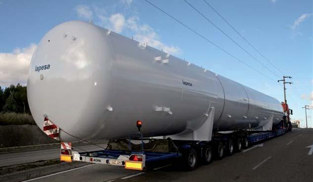
39 TANKERS FOR TRANSPORT OF LPG TANKERS FOR TRANSPORT OF LPG Semi-trailer tankers or truck-mounted tanks with the option of complete transfer equipment for LPG transport and supply. Lapesa LPG tanks, with volume capacities starting at 15 m 3 for the rigid truckmounted type and at 56 m 3 for semi-trailer tankers, adapt to the specific demands of individual projects and their requirements in terms of tank and/or vehicle characteristics. General/standard characteristics Tank for the transport of ADR class 2 liquefi ed gas under pressure. Design and construction according to ADR. Product to be contained: LPG (UN 1965), commercial propane and butane. With parasol aluminium plate covering 120º of cylinder. ADR design pressure: 25 bar. Maximum working pressure: 19.2 bar. Test pressure: 25 bar. Design temperature: ºC. Controls and tests Inspections as per design code. 100% weld x-raying. Hydraulic test at 25 bar. Testing of tightness of unit with transfer equipment. Tests according to ADR. Basic equipment Internal head valves with fl ow limiter and opening via automatic return lever, for connections to liquid phase and gas phase, with fi re-safe type ball valve, sealable with blind cap. Valve with pressure gauge and high point indicator. Background drain valve. Rotating level. Thermowell temperature indicator. Safety valve (optional). DN500 manhole located on rear head. Electrical and pneumatic installation, according to ADR. Transfer equipment Side or rear metal cabinet with liquid LPG transfer equipment. Background valves. Liquid transfer pump. Hydraulically or mechanically operated from drive shaft. Liquid LPG meter, with degasifi er and temperature compensation. Reel for winding fl exible supply hose. Hydraulically operated. Hose end with shutoff valve and ACME coupling. Decompression valves on pipes. Earth wire reel. External finish Shot-blasting of unit SA 2 ½. Anti-corrosion protection of surface with coat of polyamide epoxy (60 microns). Top coat of white polyurethane (60 microns). Options Design pressure and temperatures. Thicknesses, paint and colour of external fi nish. Signs on tank body. 39
40 SEMI-TRAILER TANKERS FOR TRANSPORT OF LPG LT42 - LT48 SEMI-TRAILER TANKERS FOR TRANSPORT OF LPG Semi-trailer tankers for transport of liquefied petroleum gases (LPG), with tank capacities of 42 or 48 m 3 on a 3-axle trailer. Products to be transported: class-2 gases (propane, butane, butylene, isobutene, propylene) and mixtures (A, A0, A01, A1, B, B1, B2, C). One compartment LPG tanker, with internal baffl es for partial transport. With aluminum sunshade comprising 120º of of the vessel, at upper side. TANKER TYPE Volumetric capacity Tare weight of semi-trailer Product (LPG, 85%, 0,5 Kg/l) load Tractor unit m 3 Tn Tn Tn LT ,8 17,7 7,0 LT ,6 20,2 7,0 Cabinet with service equipment. Total weight of fully loaded vehicle Tn 36,5 39,8 L: Set length mm * Dimensions and estimated weights Sun shade Manhole (pressure gauge, high point level, level gauge) Internal buffles Safety valves ~ Id. plate Fire Extinguisher King-pin 2" 1140 LPG transfer cabinet Landing gears L ROLLING UNIT FEATURES AXLES/WHEELS: Three axles BPW type with 20 bushing. Two wheels per axle. Disc brake: 430x45. SUSPENSION: Pneumatic. TIRES: Two wheels per axle. Tire size 385/65 R Continental. Aluminum wheel rims, semi polished. KING-PIN: 2 king-pin with plate, removable from outside, as per standard ISO 337. BRAKE SYSTEM: According to 71/320/CE Directive. Twincircuit EBS 2SM + RSS. Coupling heads as per standard ISO 1728, with fi lter. Air brake for parking with pneumatic actuators on 2 axles. PARKING LEGS: mechanically operated, telescopic. Static load: 50 ton. Max raised load: 24 ton. ELECTRICAL INSTALLATION: 24 Volt power rating, two 7-pole sockets as per ISO 1185 (24N) and 3731 (24S). Rear lights with 6 functions: reversing light, fog light, brake light, 2 position lights, fl ashers lights. Side lights. Hermetically sealed connection box. OTHERS: Rubber mudguards with rain fl aps for each wheel. Aluminum rear fender, CE approved. ACCESSORIES: Set of wheel and hub spanners. Wheel gauges. Tool box. Two 9 kg dry powder extinguishers (box included). Product plates and ADR signage. Front and rear refl ector devices. Chocks. Vessel homologation Vessel external diameter Section Material Max. operating pressure Design pressure Hydraulic test pressure VESSEL As transportable pressure vessel, according to 2010/35/UE (π marking), ADR, EN12493: mm Cylindrical, one compartment Standardized carbon steel plate for pressure vessels, resilient to -20ºC 19,2 bar 25 bar 25 bar Design temperatures From -20 to +50 ºC Inspections and controls Tank and chassis Inside vessel Outside vessel Documentation According to ADR requirements Both fi nished in white color Clean Sandblasted SA 2 ½ Primer: 65 microns epoxy polyamide Topcoad: 55 microns white polyurethane Manufacturing dossier ADR documentation Instructions manual Vehicle homologation documents 40 lapesa reserves the right to make technical changes in this product.
41 SEMI-TRAILER TANKERS FOR TRANSPORT OF LPG LT42 - LT48 P&I FOR TANKERS LT42 & LT48 SERVICE EQUIPMENT: Cabinet for liquid phase and gas phase connections (without transfer equipment). LIQUID PHASE CONNECTION (FILLING AND OUTLET): Connection to tank: 3 fl ange. 3 fl anged internal valve with excess fl ow and pneumatic actuator. Ball valve 3, fi re safe. Set WECO 2. GAS PHASE CONNECTION (FILLING AND OUTLET): Connection to tank: 2 threaded. 2 threaded internal valve with excess fl ow and pneumatic actuator. Ball valve 2, fi re safe. Set WECO 2. PURGE: Drain valve 1 ¼ with manual opening and safety valve. MANHOLE: Size ND450. Equipment included:: Manual rotary level 1. Multivalve for manometer and maximum level indicator. Pocket sensor for thermometer. SAFETY VALVE: Safety: 2 threaded valves 3 NPT, Rego brand. In upper generatrix. PNEUMATIC INSTALLATION: Pneumatic levers system for opening and closing the internal valves. Emergency stop button with auto-lock for closing internal valves and pump. HYDRAULIC INSTALLATION: Quick connection for hydraulic connection to tractor head. Valve for actuating the hydraulic motor of LPG pump. Elements to be installed on tractor head (out of Lapesa scope): - Hydraulic pump for actuating the hydraulic motor of LPG pump. - Oil tank. - Refrigeration system for hydraulic circuit. - Rest of necessary valves for the correct operation of the hydraulic circuit. OTHER ELEMENTS Tool box. Two 12 kg dry powder extinguishers (inside box). Product plates and ADR signage. Reel for grounding (earthing). OPTIONAL Tank inertization with nitrogen. lapesa reserves the right to make technical changes in this product. 41
42 SEMI-TRAILER TANKERS FOR TRANSPORT AND DISTRIBUTION OF LPG LTT42 - LTT48 SEMI-TRAILER TANKERS FOR TRANSPORT AND DISTRIBUTION OF LPG Semi-trailer tankers for transport and distribution of liquefied petroleum gases (LPG), with tank capacities of 42 or 48 m 3 on a 3-axle trailer. Products to be transported: class-2 gases (propane, butane, butylene, isobutene, propylene) and mixtures (A, A0, A01, A1, B, B1, B2, C). One compartment LPG tanker, and with internal baffl es for partial transport. TANKER TYPE Volumetric capacity Tare weight of semi-trailer m 3 Tn LTT ,0 LTT ,8 With aluminum sunshade comprising 120º of cylinder, at upper side. Product (LPG, 85%, 0,5 Kg/l) load Tn 17,7 20,2 Tractor unit Tn 7,0 7,0 Cabinet with transfer equipment. The cabinet with transfer equipment is available with or without autofi lling system. Total weight of fully loaded vehicle Tn ,0 L: Set length mm * Dimensions and estimated weights Sun shade Manhole (pressure gauge, high point level, level gauge) Internal buffles Safety valves ~ Id. plate Fire Extinguisher King-pin 2" 1140 LPG transfer cabinet Landing gears L ROLLING UNIT FEATURES AXLES/WHEELS: Three axles BPW type with 20 bushing. Two wheels per axle. Disc brake: 430 x 45. SUSPENSION: Pneumatic. TIRES: Two wheels per axle. Tire size 385/65 R Continental. Aluminum wheel rims, semi polished. KING-PIN: 2 king-pin with plate, removable from outside, as per standard ISO 337. BRAKE SYSTEM: According to 71/320/CE Directive. Twincircuit EBS 2SM + RSS. Coupling heads as per standard ISO 1728, with fi lter. Air brake for parking with pneumatic actuators on 2 axles. PARKING LEGS: mechanically operated, telescopic. Static load: 50 ton. Max raised load: 24 ton. ELECTRICAL INSTALLATION: 24 Volt power rating, two 7-pole sockets as per ISO 1185 (24N) and 3731 (24S). Rear lights with 6 functions: reversing light, fog light, brake light, 2 position lights, fl ashers lights. Side lights. Hermetically sealed connection box. OTHERS: Rubber mudguards with rain fl aps for each wheel. Aluminum rear fender, CE approved. ACCESSORIES: Set of wheel and hub spanners. Wheel gauges. Tool box. Two 9 kg dry powder extinguishers (box included). Product plates and ADR signage. Front and rear refl ector devices. Chocks. Vessel homologation Vessel external diameter Section Material Max. operating pressure Design pressure Hydraulic test pressure VESSEL As transportable pressure vessel, according to 2010/35/UE (π marking), ADR, EN12493: mm Cylindrical, one compartment Standardized carbon steel plate for pressure vessels, resilient to -20ºC 19,2 bar 25 bar 25 bar Design temperatures From -20 to +50 ºC Inspections and controls Tank and chassis Inside vessel Outside vessel Documentation According to ADR requirements Both fi nished in white color Clean Sandblasted SA 2 ½ Primer: 65 microns epoxy polyamide Topcoad: 55 microns white polyurethane Manufacturing dossier ADR documentation Instructions manual Vehicle homologation documents 42 lapesa sreserves the right to make technical changes in this product.
43 SEMI-TRAILER TANKERS FOR TRANSPORT AND DISTRIBUTION OF LPG LTT42 - LTT48 P&I FOR TANKERS LT42 & LT48 LTT42/48: scheme with auto-filling. LTT42/48: scheme without auto-filling. TRANSFER EQUIPMENT WITHOUT AUTO-FILLING TRANSFER EQUIPMENT WITH AUTO-FILLING Pump aspiration line 3 fl anged internal valve with excess fl ow and pneumatic actuator Pumping unit 3 with elastic couplings BLACKMER TLGLF3C Pump autofi lling line Ball valve 2 // 3 ¼ MACME connection Pump return line Pump impulsion line with meter Meter return line Dispensing hose Gas phase line Empty 1 ½ bypass valve CORKEN type T CAU 1 ½ back pressure check valve 1 ½ bypass valve 3 fl anged internal valve with excess fl ow and pneumatic actuator Ball valve 2 ½ // 3 ¼ MACME connection 2 units of pressure gauge with insulating lock 2 units of ball valve 2, fi re safe Volumetric fl ow meter Liquid Controls MA-7 GY10 (including temperature compensator) Ticket printer (for installation in truck tractor head) Elastic coupling // Excess fl ow valve 1 back pressure check valve Winder with pneumatic actuator Flexible hose for LPG, size 1 ¼, length 32 meters Dispensing valve with ACME coupling 1 ¾ 2 threaded internal valve with excess fl ow and pneumatic actuator Ball valve 2 2 ¼ MACME connection Ball valve 2 // 2 ¼ MACME connection SERVICE EQUIPMENT (outside the transfer cabinet): PNEUMATIC INSTALLATION: Pneumatic levers system for opening and closing the internal valves. Emergency stop button with auto-lock for closing internal valves and pump. SAFETY VALVE: Safety: 2 threaded valves 3 NPT. HYDRAULIC INSTALLATION: Quick connection for hydraulic connection to tractor head. Valve for actuating the hydraulic motor of LPG pump. Elements to be installed on tractor head (out of Lapesa scope): - Hydraulic pump for actuating the hydraulic motor of LPG pump. - Oil tank. - Refrigeration system for hydraulic circuit. Rest of necessary valves for the correct operation of the hydraulic circuit. PURGE: Drain valve 1 ¼ with manual opening and safety valve. MANHOLE: Size ND450. Equipment included:: Manual rotary level 1. Multivalve for manometer and maximum level indicator. Pocket sensor for thermometer OTHER ELEMENTS Tool box Reel for grounding (earthing). Two 12 kg dry powder extinguishers (inside box) Product plates and ADR signage OPTIONAL Tank inertization with nitrogen lapesa reserves the right to make technical changes in this product. 43


44 WORLDWIDE PROJECTS Lapesa Grupo Empresarial Pol. Ind. Malpica - Calle A, Parcela 1-A ZARAGOZA (SPAIN) Tel.: / Fax: lapesa@lapesa.es CATLPG-EN
VERTICAL BLADDER TANK
 Balanced Pressure Proportioning System Reliable Foam System Requiring Only Water Power Perfect For Tight Spaces UL Listed, ASME, National Board Registered Bladder-UL162 Approved, High Tensile Pressure
HORIZONTAL BLADDER TANK
 Balanced Pressure Proportioning System Reliable Foam System Requiring Only Water Power Perfect For Low Ceilings UL Listed, ASME, National Board Registered Bladder-UL162 Approved, High Tensile Pressure
Vertical Bladder Tanks
 DATA SHEET Vertical Bladder Tanks Features UL Listed and FM Approved for use with various ANSUL proportioners and foam concentrates 175 psi (12.1 bar) maximum allowable working pressure (design pressure)
Model MTB-ASME Vertical Bladder Tanks
 DATA SHEET Model MTB-ASME Vertical Bladder Tanks Features n UL Listed for use with various proportioners and foam concentrates n 175 psi (12.1 bar) maximum allowable working pressure (design pressure)
Model MTB-ASME Vertical Bladder Tanks
 DATA SHEET Model MTB-ASME Vertical Bladder Tanks Features n UL Listed for use with various proportioners and foam concentrates n 175 psi (12.1 bar) maximum allowable working pressure (design pressure)
Horizontal Bladder Tanks
 DATA SHEET Horizontal Bladder Tanks Features UL Listed and FM Approved for use with various ANSUL proportioners and foam concentrates 175 psi (12.1 bar) maximum allowable working pressure (design pressure)
Model MTB-ASME Horizontal Bladder Tanks
 DATA SHEET Model MTB-ASME Horizontal Bladder Tanks Features n UL Listed and FM Approved for use with various proportioners and foam concentrates n 175 psi (12.1 bar) maximum allowable working pressure
WELL COMPLETION & PROTECTION. www. .com MINERAL EXPLORATION ENVIRONMENTAL GEOTECHNICAL GEOTHERMAL ROTARY SONIC HDD
 WELL COMPLETION & PROTECTION MINERAL EXPLORATION ENVIRONMENTAL GEOTECHNICAL GEOTHERMAL ROTARY SONIC HDD www..com WELL COMPLETION & PROTECTION TABLE OF CONTENTS TABLE OF CONTENTS (FLUSHMOUNTS)... 2-5 MONITORING
Vertical and Horizontal Bladder Tanks
 DATA SHEET Vertical and Horizontal Tanks Application The ANSUL bladder tank is one component in a balanced pressure proportioning system. Its operation requires no external power other than a pressurized
FLAMMABLE GASES AND FLAMMABLE CRYOGENIC FLUIDS
 CHAPTER 35 FLAMMABLE GASES AND FLAMMABLE CRYOGENIC FLUIDS SECTION 3501 GENERAL 3501.1 Scope. The storage and use of flammable gases shall be in accordance with this chapter. Compressed gases shall also
PTF4 Pivotrol Pump (patented) version Dual Mechanism - Pressure Powered Pump
 version Dual Mechanism - Pressure Powered Pump") Local regulations may restrict the use of this product to below the conditions quoted. In the interests of development and improvement of the product, we reserve the right to change the specification without
Local regulations may restrict the use of this product to below the conditions quoted. In the interests of development and improvement of the product, we reserve the right to change the specification without
BIMBAR INFLATABLE PACKERS AND ACCESSORIES
 BIMBAR INFLATABLE PACKERS AND ACCESSORIES Geopro supplies a complete range of inflatable packers in nine different diameters from 28 up to 170mm. All our packers made of BIMBAR rubber technology are reinforced
WATER MADE EASY MARINE ENERGY MUNICIPAL INDUSTRIAL
 Capital Controls Series 71V3000 The Series 71V3000 electrically-heated vaporizer automatically vaporizes and superheats liquid chlorine, sulfur dioxide or ammonia at a rate controlled by the gas feed system.
Ball Float Steam Trap UNA 43 PN 16/CL 125/JIS 10K UNA 46 PN 40/CL 150/CL 300/JIS 10K/JIS 20K DN 80, 100, 150, 3", 4", 6"
 Data Sheet 819584-00 Issue Date: 01/17 Ball Float Steam Trap UNA 43 PN 16/C 125/JIS 10K UNA 46 PN 40/C 150/C 300/JIS 10K/JIS 20K DN 80, 100, 150, 3", 4", 6" UNA 43 hl, UNA 46 hl UNA 43 v, UNA 46 v with
Pressure Equipment Directive (PED) 97/23/EC Page 033 of 124
 97/23/EC Page 033 of 124") Pressure Equipment Directive (PED) 97/23/EC Page 033 of 124 13.7 Pressure Equipment Directive (PED) 97/23/EC 1 The Pressure Equipment Directive (PED) 97/23/EC applies to the design, manufacturing and conformity
Pressure Equipment Directive (PED) 97/23/EC Page 033 of 124 13.7 Pressure Equipment Directive (PED) 97/23/EC 1 The Pressure Equipment Directive (PED) 97/23/EC applies to the design, manufacturing and conformity
MEDICAL EQUIPMENT CATALOG
 THE MOST TRUSTED MEDICAL EQUIPMENT IN NORTH AMERICA MEDICAL EQUIPMENT CATALOG Total Components Including Bulk Oxygen Supply, Back up and Delivery Equipment Designs for High Pressure, Liquid or Bulk Applications
INDUSTRIAS IBAIONDO, HYDROPNEUMATIC TANKS
 IBAIONDO, HYDROPNEUMATIC TANKS IBAIONDO, INTRODUCTION Hydropneumatic tanks are designed to be used in potable water supply installations as a part of the pressure booster set in order to ensure the adequate
TECHNICAL DATA OBSOLETE
 June 1, 2008 Foam 240a 1. DESCRIPTION The Chemguard Bladder Tank is one component in a balanced pressure foam proportioning system. It requires no external power, other than the water pressure to ensure
SABERINDO PACIF SABERINDO PACIFIC CIFIC SABERINDO PA. A Tyco International Company
 CIF A Tyco International Company 1 Foam Concentrate CIF 3% AFFF -UL Listed -UL Canada Listed 6% AFFF 6 parts AFFF concentrate to 94 parts water -UL Listed- Foam Liquid -UL Canada Listed 3% FLUOROPROTEIN
STAD. Balancing valves DN (MD60, MD61, MD62)
") STAD Balancing valves DN 15-50 (MD60, MD61, MD62) IMI TA / Balancing valves / STAD STAD The STAD balancing valve delivers accurate hydronic performance in an impressive range of applications. Ideally suited
STAD Balancing valves DN 15-50 (MD60, MD61, MD62) IMI TA / Balancing valves / STAD STAD The STAD balancing valve delivers accurate hydronic performance in an impressive range of applications. Ideally suited
A soft sealed atmospheric safety valve with large flow capacity and soft seat tightness for steam condenser and turbine applications
 SAPAG A soft sealed atmospheric safety valve with large flow capacity and soft seat tightness for steam condenser and turbine applications Features The Sapag Series 1100 steam safety valve is used for
IECEx Certificate of Conformity Annexe
 for Certificate No.: IECEx TSA 09.004X Issue No.: 1 Equipment description pertaining to Issue 0 of this Certificate: A range of electrical power distribution, control, protection and monitoring equipment
Ball valve HKSF-W100. Ball valve HKSF-W100. RMA Kehl GmbH & Co. KG Oststrasse 17 D Kehl / Germany
 Ball valve HKSF-W100 RMA Kehl GmbH & Co. KG Oststrasse 17 D-77694 Kehl / Germany info@rma-kehl.de www.rma-armaturen.de 1 Design Features: RMA-ball valves type HKSF-W are fully welded and completely maintenance-free
Installation, Operation and Maintenance Manual for Back Pressure Regulator
 Installation, Operation and Maintenance Manual for Back Pressure Regulator Model 8860 2009 Groth Corporation IOM-8860 Rev. B 12541 Ref. ID: 95565 Page 2 of 13 Table of Contents I. INTRODUCTION 3 II. DESIGN
UIB30 and UIB30H Sealed Inverted Bucket Steam Traps for use with Pipeline Connectors
 1130050/4 IM-P113-02 ST Issue 4 UIB30 and UIB30H Sealed Inverted Bucket Steam Traps for use with Pipeline Connectors Installation and Maintenance Instructions 1. Safety information 2. General product information
Series MX pressure regulators 3/
 CATALOGUE > Release 8.8 > Series MX regulators Series MX pressure regulators MX2 ports: G/8, G1/2, G/4 - MX ports: G/4, G1 Manifold ports: G1/2 (MX2 only) Modular - Available with built-in pressure gauges
GM Series Dual-Block Multi-Function Gas Control Valves
 Installation Sheets Manual 121 Gas Combustion Combination Controls and Systems Section G Technical Bulletin GM Issue Date 0297 GM Series Dual-Block Multi-Function Gas Control Valves Figure 1: GM Series
TP1 and TP2 Temporary Cone Shaped Strainers
 1698051/2 IM-P169-07 ST Issue 2 TP1 and TP2 Temporary Cone Shaped Strainers Installation and Maintenance Instructions TP1 1. Safety information 2. General product information 3. Installation and commissioning
FOAM TANK (1/2) DATA SHEET
 DATA SHEET") FIRE FIGHTING EQUIPMENT DATA SHEET FOAM TANK (1/2) DATA SHEET JOB NO. : RFQ. NO. : ISSUE : SHEET OF 01 CUSTOMER : ITEM NO. : 02 PROJECT : QUANTITY : 03 LOCATION : SERVICE : FOAM SYSTEM 04 05 CODE & STANDARDS
FIRE FIGHTING EQUIPMENT DATA SHEET FOAM TANK (1/2) DATA SHEET JOB NO. : RFQ. NO. : ISSUE : SHEET OF 01 CUSTOMER : ITEM NO. : 02 PROJECT : QUANTITY : 03 LOCATION : SERVICE : FOAM SYSTEM 04 05 CODE & STANDARDS
TECHNICAL MANUAL. COPRA Anchoring Coupler. For Smart Bolted Connections
 TECHNICAL MANUAL Anchoring Coupler For Smart Bolted Connections Version: PEIKKO GROUP 03/2017 Anchoring Coupler For bolted connections Multi-purpose anchoring system for all bolted connections Simplifi
PRESSURE REGULATORS AND FLOWMETERS, ALL MEDICAL GASES
 PRESSURE REGULATORS ALL MEDICAL GASES In this section we propose our pressure regulators (FM series, MU and MERCURY ) and our Rs flowmeters for applications other than oxygen therapy (presented in the
94270 Vapor Guard Tank Blanketing Valve Vapor Guard Tank Blanketing Valve What is Tank Blanketing? Features How does it work?
 94270 What is Tank Blanketing? blanketing systems are used to prevent the escape of liquid vapors into the atmosphere or to prevent moisture from entering a tank and contaminating its contents. A tank
TECHNICAL DATA. Trimpac 244a. September 16, 2013
 September 16, 2013 Trimpac 244a 1. DEsCrIpTION DESCRIPTION TRIMPAC Model B-1 and B-1B is a factory-assembled trim package with an electric release module in a metal enclosure. The standard trim normally
TECHNICAL DATA. TRIMPAC Model B-5 & B-5B
 September 16, 2013 Trimpac 250a 1. DESCRIPTION DEsCRIPTIoN is a factory assembled trim package for a ed an electric/pneumatic release module in a metal enclosure. The standard trim normally required on
Tank Blanketing Pressure Regulators RHPS Series
 www.swagelok.com Tank Blanketing Pressure Regulators RHPS Series Types: pressure reducing and vapor recovery 16L stainless steel construction 1/2, 1, and 2 in. end connections Working pressures up to 22
Airfix D-E-B Installation and operating instructions
 www.flamco.nt-rt.ru Airfix D-E-B Installation and operating instructions Dear Customer, With the Airfix D-E-B membrane expansion vessel you have acquired a Flamco quality product. This expansion vessel
TANKS AND EQUIPMENT FOR PRESSURIZED LIQUEFIED GASES AT CRYOGENIC TEMPERATURE STATIC TANKS TANKS FOR SERVICE STATIONS ISO-CONTAINERS SKIDS
 TANKS AND EQUIPMENT FOR PRESSURIZED LIQUEFIED GASES AT CRYOGENIC TEMPERATURE STATIC TANKS TANKS FOR SERVICE STATIONS ISO-CONTAINERS SKIDS TANKERS FOR TRANSPORT since 1964 uaran ee of quality Tanks for
Mounting and Operating Instructions EB 3007 EN. Self-operated Pressure Regulators. Differential Pressure Regulators (opening) Type Type 42-25
 Type Type 42-25") Self-operated Pressure Regulators Differential Pressure Regulators (opening) Type 42-20 Type 42-25 Type 42-20 Differential Pressure Regulator Type 42-25 Differential Pressure Regulator Mounting and Operating
Self-operated Pressure Regulators Differential Pressure Regulators (opening) Type 42-20 Type 42-25 Type 42-20 Differential Pressure Regulator Type 42-25 Differential Pressure Regulator Mounting and Operating
Classic wine storage tanks model EXX
 Classic wine storage tanks model EXX Model EXX storage tank is a classic type E tank, without a double jacket. They are designed for storing wine under atmospheric pressure. They are characterized by top-quality
D. ACCESSORIES ADAPTER KITS IMPELLER & SEAL INSTALLATION TOOLS CARRYING HANDLES & LIFT CORDS GALVANIC PROTECTION KITS MUSHROOM STRAINER
 . ACCESSORIES AAPTER KITS IMPELLER & SEAL INSTALLATION TOOLS CARRYING HANLES & LIFT CORS GALVANIC PROTECTION KITS MUSHROOM STRAINER SLUGE STRAINERS NEMA 4 WATERTIGHT CONTROL & UAL LEVEL CONTROL (Replaces
TECHNICAL DATA. Trimpac 251a. Spetember 16, 2013
 Spetember 16, 2013 Trimpac 251a 1. DEsCrIpTION DESCRIPTION TRIMPAC Model B-6 and B-6B is a factory assembled trim package for a double interlocked preaction system with an electric/pneu-lectric release
Pilot HON 625. Entwurf. Product information. serving the gas industry worldwide
 Pilot HON 62 Entwurf Product information serving the gas industry worldwide Pilot HON 62 Application, characteristics Application Pilot for the gas pressure regulator HON 02 Pilot for outlet pressure control
Pipe threads for tubes and fittings where pressure-tight joints are not made on the threads. (requires PTFE sealing tape or liquid sealant).
.") Fittings for CO 2 Pipe Threads Pipe thread references quoted in this catalogue conform with the requirements specified in the latest issue and amendments of the following ISO Standards: ISO 7-1 (BS21)
Fittings for CO 2 Pipe Threads Pipe thread references quoted in this catalogue conform with the requirements specified in the latest issue and amendments of the following ISO Standards: ISO 7-1 (BS21)
TECHNICAL DATA MAINTENANCE AIR COMPRESSOR MODEL G-1
 Dry 131h 1. DESCRIPTION The Viking Model G-1 Maintenance Air Compressor is an electric motor-driven, aircooled, single-stage, oil-less compressor. The unit is equipped with a check valve and provides a
CAST IRON SAFETY VALVE TYPE 6301
 CHARACTERISTICS The 6301 safety valve is dedicated to protect the equipment from potential overpressure. This is an automatic device that closes when the pressure conditions are back to normal. It is a
Magnetic level switch type MR783 Instruction Manual
 Magnetic level switch Magnetic level switch type MR783 1. DESCRIPTION page 3 1.1 Operation page 3 1.2 Application page 3 1.3 Description page 3 2. SPECIFICATIONS page 3 2.1 Service Conditions page 4 2.2
TECHNICAL DATA. Trimpac 257a. September 16, 2013
 September 16, 2013 Trimpac 257a 1. DESCrIpTION DESCRIPTION The Viking Double SUREFIRE SIngle Interlock Preaction TRIMPAC Model D-2 and D-2B used with either a Model E or F Deluge Valve (A.1), a Viking
Flamco Airfix D-E. Installation and operating instructions. 1999, Flamco eps
 Airfix D-E 6442.eps GB Installation and operating instructions 1999, Exclusion of liability All operation and maintenance related technical information, data and instructions contained in these installation
TECHNICAL DATA. Trimpac 256a. October 31, 2013
 October 31, 2013 Trimpac 256a 1. DESCRIPTION The Viking SUREFIRE SIngle Interlock Preaction TRIMPAC Model D-1 and D- 1B used with either a Model E or F Deluge Valve (A.1), a Viking Easy Riser check valve
SIHI LPH-X - Liquid Ring Compressors
 - Liquid Ring Compressors LPH 50523 LPH 60527 Pressure range: Suction volume range: 0.2 to 1.5 bar 260 to 780 m³/h CONSTRUCTION Sterling SIHI liquid ring compressors are displacement compressors with a
MLS Series Liquid Level Switches. Installation and Operations Manual Section 15
 MLS Series Liquid Level Switches Installation and Operations Manual 00-02-0730 2012-11-11 Section 15 In order to consistently bring you the highest quality full featured products, we reserve the right
Si C132. Safety valves for pressure relief in accordance to PED, DIN/EN and ASME. Engineering GREAT Solutions
 Safety valves for pressure relief in accordance to PED, DIN/EN and ASME Engineering GREAT Solutions Si C132 Features The universal compact safety valve > 3 body seat sizes for appropriate size selection
Pressure Equalising Valves Model , for Differential Pressure Gauges
 Accessories Pressure Equalising Valves Model 910.25, for Differential Pressure Gauges WIKA Data Sheet AC 09.11 Applications T Isolating, pressure equalising as well as purging and air bleeding valves to
Water. VAG DUOJET Automatic Air Valve Single-chamber type PN 10/16/25/40 - DN KAT-A 1912
 Water VAG DUOJET Automatic Air Valve Single-chamber type Product characteristics and benefits Resilient seated With flange end acc. to EN 1092-2 Single chamber air valve in compact design Very high discharge
Gas Cylinder Storage Structures
 Gas Cylinder Storage Structures O These Heavy Duty Storage Structures Provide Galvanized Steel Floors Ensuring Cylinders Will Be Stored On A Level, Dry Surface $ 15,976.00 Order No: L62-3117 Custom Designs
Pneumatic valve islands
 Pneumatic valve islands The MEGA solenoid air operated spool valve JOUCOMATIC offers a concept of solenoid air operated spool valves which can be fitted together to form islands. Due to its new patented
Series IRV1000/2000/3000
 CAT.ES60-16 A Regulator Series /2000/3000 Allows adjustment of vacuum line pressure Regulator Series /2000/3000 3 sizes offered in the series Variations have been expanded to three sizes from only one
MSC-P and MSC-N Manifolds for Steam Distribution and Condensate Collection
 1170850/1 IM-P117-36 ST Issue 1 MSC-P and MSC-N Manifolds for Steam Distribution and Condensate Collection Installation and Maintenance Instructions 1. Safety information 2. General product information
Magnetic Level Gauges
 Bulletin B 03 04 Magnetic Level Gauges Remote Reading Systems Magnetic Level Switches Magnetic level gauges OPERATING PRINCIPLE The operation of the magnetic level gauge is based on some elementary physical
Storage Systems and Accessories
 Storage Systems and Accessories High Pressure Air and Inert Gases 4500-6000 PSIG DOT and ASME Cylinders High Pressure Storage Systems If an application requires storage, either in the form of a single
Gas Pressure Regulator HON 200
 Product information serving the gas industry worldwide Applications, characteristics, technical data Application Gas supply to municipal, industrial and individual consumers Regulator for low-load rails
Premium Series. Economical Price & Reliable Performance. High Quality. Rust-Resistant. Long Life. Tamper-Resistant locking Screw.
 Premium Series High Quality Forged Brass Body Rust-Resistant Nickel Plated Finish Long Life Corrosion Resistant Valve Seat Economical Price & Reliable Performance Tamper-Resistant locking Screw Reduces
For use with select HPC Fire Pits ONLY- refer to product catalog or website. 100K BTU Maximum WARNING: FOR OUTDOOR USE ONLY
 For use with select HPC Fire Pits ONLY- refer to product catalog or website. 100K BTU Maximum : FOR OUTDOOR USE ONLY Small Tank LP Kit (STLPK) Installation & Operation Instructions Installation We suggest
ISO INTERNATIONAL STANDARD. Cryogenic vessels Pressure-relief accessories for cryogenic service Part 1: Reclosable pressure-relief valves
 INTERNATIONAL STANDARD ISO 21013-1 First edition 2008-06-15 Cryogenic vessels Pressure-relief accessories for cryogenic service Part 1: Reclosable pressure-relief valves Récipients cryogéniques Dispositifs
Accu Max Limited Warranty
 Form #460 Rev B Phone: 69-789-6700 Fax: 69-78-840 E-mail: sales@marshallexcelsior.com www.marshallexcelsior.com NOTE: Before installing, inspect float gauge assembly for shipping damage that may affect
SPOOL VALVES. pilot operated single/dual solenoid (mono/bistable function) ISO mm - pad mounting body M12 connection
 ISO mm - pad mounting body M12 connection") SPOOL VALVES pilot operated single/dual solenoid (mono/bistable function) ISO 07-8 mm - pad mounting body M connection x/ - / - / Series 0 ISO 07- (8 mm) FEATURES M connection on top of valve: reduces
SPOOL VALVES pilot operated single/dual solenoid (mono/bistable function) ISO 07-8 mm - pad mounting body M connection x/ - / - / Series 0 ISO 07- (8 mm) FEATURES M connection on top of valve: reduces
LPS Product Guide. LPS Series Nitrogen Generators. N2-GEN LPS TM - Layup Protection System Copyrighted All Rights Reserved
 LPS Product Guide N2-GEN LPSTM LPS Series Nitrogen Generators N2-GEN LPS TM - Layup Protection System Copyrighted All Rights Reserved - 2014 p 888 526 6284 e info@southteksystems.com w www.southteksystems.com
Chlorine Supply Containers And Piping
 Chlorine Supply Containers And Piping Containers Chlorine is packaged in containers as a liquefied gas under pressure, resulting in the container having both a liquid phase and a gas phase. When removing
WEDGE-ALL Wedge Anchors
 WEDGE-ALL Wedge Anchors The Wedge-All wedge anchors are a non-bottom bearing, wedge-style expansion anchor for use in solid concrete or grout-fi lled masonry. A one-piece clip ensures uniform holding capacity
THE BP-301 SERIES. Operating and Service Manual. Series includes all variants of BP-301 (LF 0.1Cv / MF 0.5Cv)
") THE BP-301 SERIES Operating and Service Manual Series includes all variants of BP-301 (LF 0.1Cv / MF 0.5Cv) Issue B October 2015 1 TABLE OF CONTENTS 1. Description... 3 2. Installation... 3 3. Operation...
THE BP-301 SERIES Operating and Service Manual Series includes all variants of BP-301 (LF 0.1Cv / MF 0.5Cv) Issue B October 2015 1 TABLE OF CONTENTS 1. Description... 3 2. Installation... 3 3. Operation...
GAS DISTRIBUTION PRODUCTS TRANSITION FITTINGS
 GAS DISTRIBUTION PRODUCTS TRANSITION FITTINGS CONTINENTAL INDUSTRIES, INC. The Ultimate Connection CONTINENTAL INDUSTRIES, INC. ABOUT US THE ULTIMATE CONNECTION Our Company Continental Industries, Inc.,
THE MF-400 SERIES. Operating and Service Manual. Series includes all variants of MF-400/401
 THE MF-400 SERIES Operating and Service Manual Series includes all variants of MF-400/401 Issue A October 2013 1 TABLE OF CONTENTS 1. Description... 3 2. Installation... 3 3. Operation... 4 4. Special
Booster Regulator/Air Tank
 Booster Regulator/Air Tank Increase factory air pressure by up to 4 times! Air-only operation requires no power supply, reduces heat generation, and Boost pressure allows easy installation. NEW Renewed
Inflatable Packer Single & Double. Single & Double Packer Dimension. Wireline Packer. Water Testing Packer (WTP) Packer
 Packer") Inflatable Packer Single & Double Single & Double Packer Dimension Wireline Packer Water Testing Packer (WTP) Packer Packer Working Pressure & Depth Chart Packer Water Hand Pump Packer Air Driven Pump
Inflatable Packer Single & Double Single & Double Packer Dimension Wireline Packer Water Testing Packer (WTP) Packer Packer Working Pressure & Depth Chart Packer Water Hand Pump Packer Air Driven Pump
TECHNICAL DATA OBSOLETE
 April 9, 2009 Preaction 326a 1. DESCRIPTION Viking supervised Double-Interlocked Electric/Pneumatic Release Preaction Systems utilizing the Viking G-4000P Deluge Valve. The small profi le, lightweight,
Reaction apparatus with agitator and double wall vessel 0,1-5 litres
 Reaction apparatus with agitator and double wall vessel 0,1-5 litres We deliver the systems without motor, but with manual and certificate. The double cardan coupling enables a tension-free drive of the
Summary of the MRA LPG Codes of Practice
 Summary of the MRA LPG Codes of Practice COP A1 DESIGN and INSTALLATION Code COP A1 deals with above ground installations where LPG is stored under pressure at ambient temperatures in fixed vessels larger
Self-operated Pressure Regulators for special applications
 Self-operated Pressure Regulators for special applications Type 2357-31 Pressure Build-up Regulator with safety function and integrated excess pressure valve Application Pressure regulators for cryogenic
1.0 - OPENING AND CLOSING THE DOOR
 The purpose of this manual is to provide the user with instructions on how to safely open and close, how to conduct routine maintenance, and how to install the PEI TWINLOCK Closure on a pressure vessel.
Dual position solenoid valve Type ICSH 25-80
 Data sheet Dual position solenoid valve Type ICSH 25-80 ICSH dual position solenoid valve belongs to the ICV family and consists of an ICV housing, an ICS insert together with an ICSH top cover with 2
TRADITIONAL HIGH VIBRATION HOSE SYSTEM THE STANDARD FOR MANY AUTOMOTIVE APPLICATIONS
 O-Ring Face Seal Hose TRADITIONAL HIGH VIBRATION HOSE SYSTEM THE STANDARD FOR MANY AUTOMOTIVE APPLICATIONS O-Ring Face Seal METAL FORMING SOLUTIONS THE STANDARD FOR MANY AUTOMOTIVE APPLICATIONS Table of
VACCUPERM Vacuum chlorine gas dosing systems
 VACCUPERM Vacuum chlorine gas dosing systems Vaccuperm, precise and safe dosing. www.clorep.es VACCUPERM INTRODUCTION Vaccuperm provides a proven and reliable technology of vacuum gas dosing. Handling,
INTERPLANT STANDARD - STEEL INDUSTRY CODE OF PRACTICE FOR SELECTION, Corresponding IS does not exist
 INTERPLANT STANDARD - STEEL INDUSTRY IPSS CODE OF PRACTICE FOR SELECTION, LAYING OF MOIST FUEL GAS LINES Corresponding IS does not exist IPSS:1-06-014-17 (Third Revision) Formerly : IPSS:1-06-014-02 (Second
Rapidmain Installation Guide
 Rapidmain Installation Guide Aluminium Compressed Air Pipe Work Installation Guide Trafalgar Court, Waterloo Ind Estate, Widnes Cheshire. UK. Ref: Rapidmain installation guide 4b Index 1. Rapidmain fittings:
Model: AT-1000 L.P.G. FREEZE VALVE
 Model: AT-1000 P/N: 2156006200 3829 Forest Parkway Suite 500 Wheatfield, NY 14120-3763 Phone: 716-629-3802 Fax: 716-693-9162 solutions@viatran.com www.viatran.com 1 OPERATION AND MAINTENANCE INSTRUCTIONS
Pressure reducing valve, direct operated
 Electric Drives and Controls Table of contents Hydraulics Pressure reducing valve, direct operated Model ZDR 6 D Nominal size 6 Series 4X Maximum operating pressure 20 bar (3050 PSI) Maximum flow 50 L/min
MSC Guidelines for Independent Fuel Tanks
 References: Contact Information a. 46 CFR 58.50 (Independent Fuel Tanks) b. 46 CFR 119.440 (Independent Fuel Tanks) c. 46 CFR 182.440 (Independent Fuel Tanks) C. J. Robuck, LCDR, Chief, Engineering Division
Issue 2 May Guidance on the design, construction and testing of standard rail tank cars for the transport of chemicals in bulk
 Issue 2 May 2016 Guidance on the design, construction and testing of standard rail tank cars for the transport of chemicals in bulk INTRODUCTION This document provides guidance on the design and construction
Single-Phase Pad-Mounted Distribution. Single-Phase Pad-Mounted Distribution Transformers KVA
 62-10 Single-Phase Pad-Mounted Distribution Catolog Transformers Section Howard Industries, Inc. Certifi ed to ISO 9001:2015 62-10 Single-Phase Pad-Mounted Distribution Transformers 5-500 KVA 10002179
64 Series Pressure Reducing Regulators
 Instruction Manual Form 1245 64 Series March 2006 64 Series Pressure Reducing Regulators W1943 Figure 1. 64 Series Regulator Introduction Scope of Manual This manual provides instructions for the installation,
MST21 Stainless Steel Balanced Pressure Thermostatic Steam Trap
 1250650/6 IM-P125-07 ST Issue 6 MST21 Stainless Steel Balanced Pressure Thermostatic Steam Trap Installation and Maintenance Instructions 1. Safety information 2. General product information 3. Installation
TECHNICAL DATA. Q = C v P S
 January 6, 2012 Preaction 348a 1. Description Viking supervised Surefire Preaction Systems utilize the Viking G-6000P Valve. The small profile, lightweight, pilot operated Viking G-6000P Valve comes complete
RS(H)10,15 USER MANUAL. Read the complete manual before installing and using the regulator.
10,15 USER MANUAL. Read the complete manual before installing and using the regulator.") RS(H)10,15 USER MANUAL Read the complete manual before installing and using the regulator. WARNING INCORRECT OR IMPROPER USE OF THIS PRODUCT CAN CAUSE SERIOUS PERSONAL INJURY AND PROPERTY DAMAGE. Due to
RS(H)10,15 USER MANUAL Read the complete manual before installing and using the regulator. WARNING INCORRECT OR IMPROPER USE OF THIS PRODUCT CAN CAUSE SERIOUS PERSONAL INJURY AND PROPERTY DAMAGE. Due to
INSTRUCTION MANUAL. Gas Salamander
 INSTRUCTION MANUAL Gas Salamander This manual contains important information regarding your unit. Please read this manual thoroughly prior to equipment set-up, operation and maintenance. Failure to comply
TECHNICAL DATA. Q = C v P S
 January 6, 2012 Preaction 333a 1. Description Viking supervised Surefire Preaction Systems Utilize the Viking G-3000P Valve. The small profile, lightweight, pilot-operated Viking G-3000P Valve comes complete
General page Straight unions page Angle unions page Tee and L-unions page Gauge connection unions page 42
 C 2610-00 Table of contents General page 3-13 DILO unions for pressure ranges from 100 320 bar Straight unions page 14-25 Weld-on tube unions page 14-16 Screw-in tube unions page 17-25 with metric / Whitworth-
Standard Gas Countertop Griddle
 Standard Gas Countertop Griddle This manual contains important information regarding your unit. Please read the manual thoroughly prior to equipment set-up, operation and maintenance. Failure to comply
Installation Instructions MODEL VSTI-A020 Tank Indicator Installation Model: VSTI-A020, Stainless Reverse Read System Versa Steel Inc. Guide Cables No
 Tank Indicator Installation Model: VSTI-A020, Stainless Reverse Read System Guide Cables No Guide Cables 1 August 4, 2011 Assembly Instructions: (Shown with a 2 board, 12 ft kit) ITEM NO. PART NUMBER DESCRIPTION
Model: AT-1000 L.P.G. FREEZE VALVE
 Model: AT-1000 P/N: 2156006200 3829 Forest Parkway Suite 500 Wheatfield, NY 14120-3763 Phone: 716-629-3802 Fax: 716-693-9162 solutions@viatran.com www.viatran.com 1 OPERATION AND MAINTENANCE INSTRUCTIONS
ASYBCO 90 O ELBOW LONG RADIUS O.D. I.D.
 90 O ELBOW LONG RADIUS Standard weight Extra strong Schedule 160 Double extra strong ASTM A-234 ASME / ANSI B16.9 Carbon and ferritic alloy steel Produced from X-rayed, stress-relieve welded pipe. Welds