Slipso400 August 17, 2006
|
|
|
- Ralph Tyler
- 6 years ago
- Views:
Transcription

1 Slipso400 August 17, 2006
2 Contents 1 Introduction 3 2 Preparation 4 3 Wing Preface Building Assembly Shaping Reinforcements Covering Ailerons Fuselage Preface Making the Formers Building the Fuselage Tail 14 6 Final Assembly Wing fixation to the fuselage Tail fixation to the fuselage Motor installation Flying Control surface setup Elevator Ailerons
3 7.1.3 Flaps Battery Selection NiMH Li-poly Prop selection V Speed-400 can motor Brushless in-runner Center of Gravity (CoG, CG) Launching Landing Beyond here Web sites containing further details on various build processes. 22 2
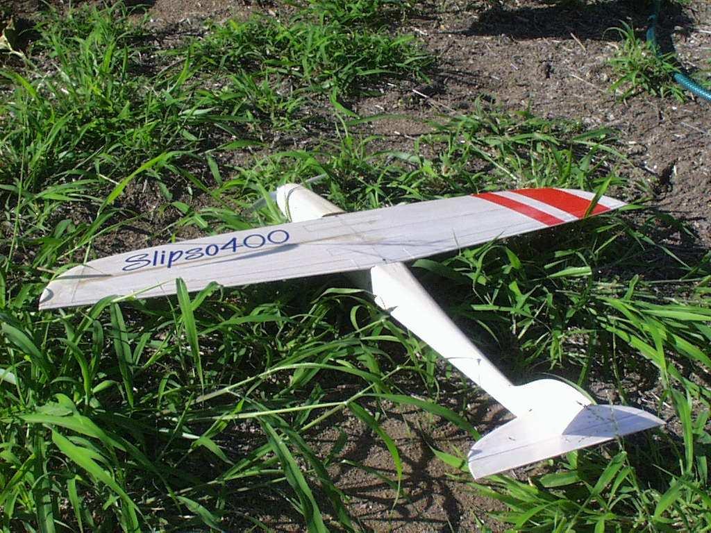
4 Chapter 1 Introduction Designed as an introduction to the fun sport of club racing, the Slipso400 can accomodate speed-400 sized motors and battery packs up to 7 cell 2/3A configurations. The Slipso400 has a 6mm (1/4 ) solid balsa wing covered with laminating film or fiberglass. The fuselage is made of balsa sheet, triangular stock and balsa-ply formers, subsequently covered in fiberglass using waterbased polyurethane clear varnish. The tail feathers are made from solid sheet balsa. In no way is the Slipso400 a beginners plane. The Slipso400 is a low cost entry level racing plane however it s assumed that the builder/pilot has had at least three other planes and is comfortable with ailerons. With speeds in excess of 160km/hr (100mph) possible this plane is most certainly not a toy. Specifications Wingspan: 750mm (30 ) Length: 555mm (22.5 ) Flying weight: g (12 14oz) Motor: 6V Speed 400 brushed can motor or Hacker B L for serious speed. Suggested Prop: APC 4.5x x 4.75 Suggested Battery: 2S1800-2S2200mA lipo Controls: Ailerons, Elevator and Throttle Construction: Solid balsa wing with laminating film covering. Shaped sheet-box fuselage partially covered with 2oz fiberglass cloth, sealed with water based polyurethane. 3
5 Chapter 2 Preparation To make building the Slipso400 as efficient as possible, it s recommended you have the following resources and tools at your disposal Workbench of at least 1500 x 500mm (5 x 2.5 ) in size (for general building) Fast CA glue Whiteglue (PVA, Aquahere, Weldbond etc) Epoxy (may be supplanted by Polyureathane/Gorilla glue etc) Balsa Plane (not essential but makes building a lot more plesant) Xacto type No.11 blade knife Assortment of clamps and pegs Straight-edge rule Patience (yes, seriously, patience, your plane will turn out a lot nicer if you don t rush it ) Throughout this manual there will be references to using various tools to do certain tasks, you are not obliged to follow strictly what is done in the manual, everyone has their own preferred methods. Gluing of items is additionally a rather subjective affair, the selection of glues in this manual is based on anticipated loads and stresses that a particular join may be required to take, if you feel that you prefer another selection of glue then certainly go ahead, it is after all a personal judgement call. It is of my personal opinion that using PVA/Whiteglue such as Weldbond or Alphiatic resin will result in a much better model than using CA, not to mention the health problems that CA can potentially induce. Some people may laugh at the requirement of patience, the truth is that after years of building, it would appear that patience can actually speed up a build and result in a better quality finished item, this is because there will be less accidents due to rushing an item (CA is a wonderful glue that bonds fast and strong but it can commit mistakes equally as well). Examine your kit and make sure that all the parts are included and none of the items are missing from the laser cut out sheets. Also check that none of the parts in the kit are broken. It helps at times if you mark off the parts on the plan as this gives your mind a chance to associate where things go. All dimensions and weights are specified in metric. 4
6 Chapter 3 Wing 3.1 Preface The Slipso400 wing will be taking the greater portion of all the forced felt by the plane while it s wipping around the sky low and fast. The only other part on the Slipso400 that will feel the pressure in the same magnatude is the wing-mount bolt holders in the fuselage. There are ten (10) pieces to make up the Slipso400 wing; 2 x Leading half quarters. 2 x Trailing half quarters. 2 x 100x20mm (4 x 4/5 ) center join blocks. 2 x Wingtips 2 x Trailing Edge strips Please note - Due to the nature of laser cutting you will need to flip over various pieces in order to make the kerfing angle match up to provide a nearly seamless join. Decide up front how you re going to cover your wing. We find that using 80 micron (3.0mil) laminating film on the bottom and 40 micron (1.5mil) on the top in combination with a single strip of CF tow on the wing underside is more than ample for most power configurations up to 100W. For higher powered applications you may consider totally glassing the wing. 3.2 Building Assembly Carefully examine all 10 parts used to build the wing and remove any excess balsa notches with the knife (Figure 3.1) Assemble the parts making sure that you invert one panel on each side so that the kerfing from the laser cutting process match up. 5


 it means you will be able to turn tighter and maintain speed.")
7 If required, trim the width of the two reinforcement balsa pieces to ensure that both halves of the wing match up accurately. Glue and assemble the wing together, leaving it to rest on a sheet of plastic or laminating film and weigh down with books or other suitable weights to ensure that the wing does not warp while drying. (Figures 3.2,3.3 and 3.4) Figure 3.1: Dry fitting of parts Figure 3.2: Bringing the wing halves together Figure 3.3: Wing glued Figure 3.4: Keep the wing flat Shaping Despite being only 6mm thick, the wing section (Airfoil) of the Slipso400 wing can make a considerable difference in flight, however even if you do not obtain a near ideal wing section the Slipso400 will still fly. The quality of the wing section will certainly be something which can separate winners and almost-winners. As an example, if you can manage to make a good wing section that allows you to pull an extra one degree of attack without having the airflow detach from the wing (high drag, rapid speed loss) it means you will be able to turn tighter and maintain speed. We will not be discussing how to make an ideal section here, rather we ll describe how to start out and let you, the builder take it from there. As a basic starting point, shave down the LE (Leading Edge) to just below mid thickness (4mm 1/5 ) and sloping back to the top 25 30mm ( ) in from the LE. 6
 and 45 55mm (2 ) in from the TE. Sand the wing down to provide a nice smooth surface and curvature.")

. 3.2.")

8 Figure 3.5: Wing with sanded profile - note the upward curved tips Shave the TE (Trailing Edge) down to 1.5mm (1/16 ) and 45 55mm (2 ) in from the TE. Sand the wing down to provide a nice smooth surface and curvature. Take special note of the LE section to ensure that it has a nice egg profile. Do NOT attempt to round the LE to a circular profile as this will cause a considerable amount of drag. A sharp egg-point nose will produce less drag but stall sooner (faster). A blunt egg-point nose will produce more drag but stall later (easier) Reinforcements The basic balsa Slipso400 wing covered with film will most likely suffice for normal speed-400 racing. For the purpose of safety and peace of mind, you may wish to consider applying a strip of CF tow or cloth along the underside of the wing across the span. Standard 12,000 strand tow bonded down with epoxy, CA or hotglue will provide ample wing tensile strength for those extra tight turns or emergency Oh dear moments. Figure 3.6: Masking tape applied for hotglue tips Figure 3.7: CF positioned and taped down 7
 and 40 micron (1.5mil) laminating film. The 80 micron film is used on the underside of the wing and provides yet more tensile strength for handling tight turns.")
9 3.2.4 Covering There s many choices of potential coverings that can be used for the Slipso400 wing. We have found the simplest and cheapest is to use a combination of 80 micron (3.0mil) and 40 micron (1.5mil) laminating film. The 80 micron film is used on the underside of the wing and provides yet more tensile strength for handling tight turns. The topside 40 micron film provides a light, strong and low drag finish. One could us 40 micron film on both sides, especially when combined with the CF tow/cloth reinforcements - however using the heavier 80 micron film does give additional peace of mind from mid-turn wing clapping events (and subsequent clapping from the peanut gallery ). Figure 3.8: Wing being covered Ailerons By default the Slipso400 comes with ailerons marked out by the laser cutting. These ailerons are sufficiently effective at medium deflection rates for general purpose. If you wish to have extremely agressive roll rates you may consider making the ailerons an additional 6mm (1/4 ) deeper. Ailerons can be cut cleanly from the covered airframe and hinged according to preference. The simplest of hinging methods is to bevel the underside of the aileron and use tape or 40 micron laminating film hinges on the topside. When bevelling the ailerons make sure you do not cut away any balsa from the top otherwise it will result in an ugly gap in the top-hinge. If you do accidently cut away too much balsa it would be best to make a new aileron from fresh material. 8

10 Chapter 4 Fuselage 4.1 Preface Building the fuselage isn t a complex task however you d be wise to take your time and it s strongly recommended to use PVA or Alphiatic, this gives you the time to setup the join as well as providing a flexible bond that can tollerate less than perfect landings as well as high stresses. 4.2 Making the Formers To provide an extra level of strength, the formers for the fuselage are made by creating a balsa plywood from 3 layers of 1.5mm (1/16 ) balsa. Of the three (3) pieces there is one that has the grain at 90 degrees to the other two, this piece is the middle piece. Use PVA glue and assemble all the formers together and place under pressure until dry. Using two glass sheets with books or old batteries works well. Figure 4.1: Fuselage formers under glass 4.3 Building the Fuselage Join the two fuselage sides, F2 and F3 with PVA glue and clamp. F2 and F3 are symetrical so you can insert them either way up. (Figure 4.2) 9

 Figure 4.")
 Remove BD1 and BD2 once the glue for the formers has dried.")


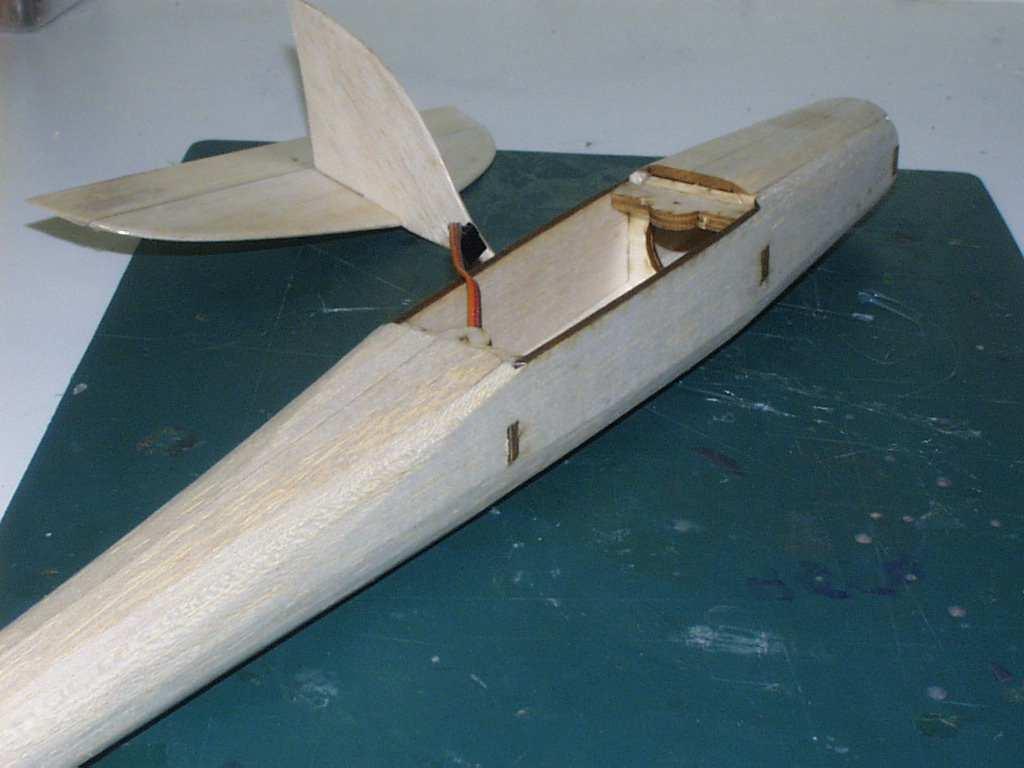
11 Insert, glue and clamp F1. (Figure 4.3) Insert but DO NOT GLUE BD1 and BD2 (Bottom Deck 2). They are used to ensure the airframe is correctly aligned at this point. We do not glue them in yet because we have to add the triangular stock first. Figure 4.2: F2 and F3 glued Figure 4.3: F1 added with bottom deck Glue in the fuselage tail alignment former. (Figures 4.4, 4.5 and 4.6) Figure 4.4: Tail alignment former Figure 4.5: Check alignment (rear) Figure 4.6: Check alignment (front) Remove BD1 and BD2 once the glue for the formers has dried. Cut to length and glue in 6mm triangular stock along the length of the bottom of the fuselage. The reason we did not do this before putting the formers in is because if we tried to do that the triangular stock would resist the bending of the fuselage sides and crush the balsa causing it to be weaker. Take notes that the triangular stock has to sit flush with the notches in the fuselage sides. (Figure 4.7) Insert panels BD1, BD2 and BD3 with their laser marked center lines on the outside (this is used later to ensure proper alignment. Ensure that the tristock glues and sits flush with the bottom panels. Install the wing bolt hold-downs. Be aware that they are of different sizes for the front and the back. (Figures 4.8 and 4.9) 10

 Install cable guide and an ample length of control wire to extend all the way to beyond the underside of the tail former.")
 Install the rear top-deck (TD2) with the laser-marked center line facing up.")
 At this point you may wish to temporarily install the motor/spinner to give a guide for how far to shape down the nose section.")
12 Figure 4.7: Triangular stock glued in Figure 4.8: Wing mount formers installed Figure 4.9: Bottom decking and tristock installed At this point you need to commit yourself to installing the elevator servo. A typical 9g (0.3oz) class servo provides ample strength for a brushed speed-400 setup. Tape and hot-glue in the servo to the rear side of F3. (Figure 4.10) Install cable guide and an ample length of control wire to extend all the way to beyond the underside of the tail former. (Figure 4.11) Install triangular stock to the top side of the fuselage. (Figures 4.12 and 4.13) Install the rear top-deck (TD2) with the laser-marked center line facing up. Using a razor plane, shave down the fuselage to a round profile and finish off with sand paper. (Figures 4.14 and 4.15) At this point you may wish to temporarily install the motor/spinner to give a guide for how far to shape down the nose section. (Figures 4.16 and 4.17) Finish the fuselage according to preference. We find that applying 2oz glass up to F3 (wing TE former) is sufficient for most applications. (Figure 4.18) 11


13 Figure 4.10: Elevator servo installed Figure 4.11: Control guide installed Figure 4.12: top-rear Appling tristock to Figure 4.13: Top-front tristock Figure 4.14: Front of fuselage shaved to shape Figure 4.15: Rear of fuselage shaved to shape 12


14 Figure 4.16: Spinner fitted and marked Figure 4.17: Nose sanded to smooth profile Figure 4.18: 2oz glass cloth on fuselage 13
. Join the elevator to the horizontal stab with masking tape (Figure 5.")

15 Chapter 5 Tail Building the tail for the Slipso400 is a fairly simple affair but it is very important to ensure that you build it square and keep the elevator hinge as slop free as possible (not too difficult). Join the elevator to the horizontal stab with masking tape (Figure 5.1) Turn over and shave down the shave down the TE as much as practical, try to get to at least 1mm (1/25 ) thin, preferably closer to 0.5mm (1/50 ) (Figure 5.2) Figure 5.1: Horizontal stab and elevator joined with masking tape Figure 5.2: Elevator shaved down Fold up the elevator and shave in the bevel for the hinge. As with the ailerons, do not over cut the bevel else you ll have ugly gaps in your hinge. (Figures 5.3 on the following page and 5.4 on the next page) Sand down the horizontal and vertical stab to a smooth profile and test fit. (Figure 5.6 on the following page) Cover tail surfaces with 40 micron laminating film to provide a very low drag surface. You can use the top-covering of the horizontal-stab as a live hinge and use 12mm (1/2 ) wide clear scotch tape on the underside of the hinge. 14


16 Figure 5.3: Elevator folded over Figure 5.4: Beveled elevator Figure 5.5: Elevator after shaping Figure 5.6: Test fitting the tail Glue the tail together and keep it flat and square. Glue the tail unit together after the fuselage has been glassed and sealed. 15
17 Chapter 6 Final Assembly When the tail, fuselage and wing have all been finished you can finally bring them together to create the complete Slipso400 airframe. 6.1 Wing fixation to the fuselage The Slipso400 wing comes with 4mm (1/6 ) bolt holes already laser cut into it with the subsequent wing mount receptors in the fuselage having a pilot hole cut. A blind nut mounted onto the underside of the fuselage receptors will provide for a suitable hold-down. When installing the fuselage wing hold-downs make sure that you provide ample gluing, these are the only items holding the wing to the fuselage. You may wish to install triangular stock around the underside of the hold-downs to increase their strength. Make sure when you install the wing bolts that the center line of the wing (where the two halves join) is kept in alignment with the center lines marked on the top deck panel sheets. 6.2 Tail fixation to the fuselage Once the wing has been mounted onto the fuselage, the tail can be fitted. Before gluing the tail to the fuselage check that the laminating film on the underside of the tail has been removed as required to ensure that a balsabalsa bond occurs. Triple check the tail horizontal stab alignment to ensure that it s parallel to the wing. 6.3 Motor installation Depending on the motor used different installation methods will be required. Use 5.5 6mm x 2.3mm metric screws directly through F1 for the Speed-400. Make sure you strengthen the balsa supporting the screws by CA ing them and allowing to soak for 15 minutes. Use a double-wrapped 1.5mm balsa holder and glue with PVA. Sand the front edges of the holder down to fit snugly into the nose of the fuselage before gluing. 16

18 Figure 6.1: Motor mount made from two layers of 1.5mm (1/16 ) balsa 17
19 Chapter 7 Flying 7.1 Control surface setup Elevator If you have the ability on the transmitter, it s recommended to have either dual-rates or expo-rates setup for the Slipso400 elevator. During normal flight there is very little movement required, however on landing approach with power off it s often useful to have a lot more elevator movement to facilitate washing off speed. In-flight movement range is +/-3mm (1/8 ) of deflection (yes, a very small amount). Landing movement range is +/-6mm (1/4 ) Ailerons As with the elevator, the ailerons do not need a lot of deflection. In fact, with excessive deflection you risk adverse stability issues including spontaneously snaps and flat spins. If you need greater roll rates it s suggested that you increase the average width of the Slipso400 ailerons rather than attempting to increase the deflection. Medium Aileron deflection: +/-6mm (1/4 ) Flaps If you ve decided to use a two servo aileron setup you can program your TX to provide a flap/reflex facility which can be useful for landing approaches. With flaps you can consider increasing your lower deflection maximum to 6mm but it s not recommended that you go beyond 6mm (1/4 ) for the upper deflection. 7.2 Battery Selection NiMH The standard battery for most club racing is a 7 cell (8.4V) mA 2/3A NiMH pack. At the time of writing the highest capacity cells are from Intellect IB1200 and IB1400 cells. Other popular cells are the GP1100 s. 18
20 7.2.2 Li-poly For starting out, a 2S1800 to 2S2200mA with 10 15C average discharge rate works very well with speed-400 can motors. Despite having a lower nominal voltage of 7.4V versus the 8.4V of a 7 cell pack the lipo can actually end up having a higher real voltage during the flight due to the internal resistance differences. The great thing about using a lipo pack is that the AUW for the plane can be lower for the same flight times or you can choose to keep the same AUW and have longer flight times. 7.3 Prop selection V Speed-400 can motor Ideal prop selection will vary dramatically based on your battery selection and prevailing atmospheric conditions to obtain optimal performance. On 7 cell NiMh or 2S lipo configurations an APC 4.75x4.75 is a good starting point. On 3S lipo an APC 4.2 x 4.5 would be more ideal, be aware though that nearly all brushed speed 400 motors are not really designed to withstand such voltages Brushless in-runner There is such a massive range of in-runners that it s difficult to suggest a prop for them, however, starting with a 7cell-2S configuration on a 3000kV 20x40mm in-runner an APC 4.5x4.7 could be a good start. For higher kv or 3S configurations an APC 4.1 x 4.1 may be more idea so as not to overly stress the motor in the much higher rpm (30,000rpm+) environments. 7.4 Center of Gravity (CoG, CG) The CG is located between 28 and 32mm ( ) from the LE (Leading edge) as measured at the sides of the fuselage. Deviations from this can be based on personal flying preferences. 7.5 Launching For Speed-400 brushed installations, launch at full throttle over the shoulder with a horizontal angle (don t try to launch upwards aggressively, the plane will only stall and crash). The Slipso400 will sink about 1 meter before it has picked up enough speed to start flying. Allow it fly straight at a very slight upward angle to gain more speed before commencing the first turn and climb. 7.6 Landing The Slipso400 is a surprisingly fast plane when it comes to landing but with a few tips you can make it easier. 19
21 Approach the landing from at least 15m (45 ) high as you perform the final turn from about 50 70m (150 ) down wind. Kill the throttle just as you commence the final turn to line up with the landing strip. As you turn the high attack angle on the turn will cause the Slipso400 to wash off a lot of its speed. WARNING - do not turn if you are already quite slow or lower than 5m. As with most racing planes of this type they are quite susceptible to tip stall at lower speeds. Without sufficient height or speed a crash may result. The Slipso400 should come into contact, or be very close to contact with the ground as it passes your position, if you re too high and fast then power up and go around again. Do not use excessive aileron movements on landing, remember you do not have a rudder so you cannot correct a misaligned approach too easily - better go around and do it again. If you find that the landings are too hot then try leaving the throttle at 10 15%, this has a very aggressive air-brake type effect, so much so that you may find the Slipso400 will want to land well short of your position. 20
22 Chapter 8 Beyond here... After you have mastered the Slipso400 you may well be looking for more performance, moving up from a standard brushed speed-400 motor to a Brushless in-runner will provide the single most dramatic improvement in performance. Take care when upgrading to brushless to ensure that your airframe has been built to handle the extra stresses. Thank you again for building and flying the Slipso
23 Chapter 9 Web sites containing further details on various build processes. Using laminating film to cover wings. Using laminating film to cover tails. Video demonstrating covering with laminating film Using hotglue and carbon fiber tow for reinforcements Using water based polyurethane and fiberglass Video demonstrating glassing with water based polyurethane 22
24 23
EPP Version Building Notes Updated
 EPP Version Building Notes Updated 12-10-2013 The Zulu covers a wide range of flying conditions: slope soaring in light to strong lift, thermalling, aerobatics, discus launches, and combat; for skill levels
Model Aero Sportster Indroduction
 1 Model Aero Sportster Indroduction We are excited to introduce the Model Aero Sportster! Inspired by classic designs of the past, the Sportster is a relaxing slow flyer, equally at home indoors or outside
Model Aero AT-6 Texan Introduction
 1 Model Aero AT-6 Texan Introduction We are excited to introduce the Model Aero AT-6 Texan! Originally used as an advanced trainer by the U.S. Armed Forces, the AT-6 is a relaxing slow flyer, equally at
ANGEL 2000 glider ARF ASSEMBLY MANUAL. Specifications: MS: 129
 WWW.SEAGULLMODELS.COM ASSEMBLY MANUAL ANGEL 2000 glider Graphics and specifications may change without notice. MS: 129 ARF Specifications: Wingspan---------------78.7 in ( 200cm). Wing area---------------582.8sq.in
aero naut Electric Model Aeroplane Quido Order-No. 1303/00
 aero naut Electric Model Aeroplane Quido Order-No. 1303/00 Quido is a small model that accompanies you wherever you go. The prefabricated parts are mostly balsa and just need to be assembled according
Designed by Steve Shumate Adapted from the North Star design by Laddie Mikulasko. Polaris EX Introduction
 1 Model Aero Polaris Designed by Steve Shumate Adapted from the North Star design by Laddie Mikulasko Polaris EX Introduction We re excited to introduce the Polaris EX seaplane parkflyer! Based on the
Horizontal Fuselage. Top Vertical Fuselage 1. Lay out the Top Vertical Fuse Front(1), Top Vertical Fuse Back(2), and Vertical Stabilizer(3).
, Top Vertical Fuse Back(2), and Vertical Stabilizer(3).") Rumbuilder 71 B-17 Congrats on your Rumbuilder B-17! We re glad you chose to fly with us! If you have any problems, or missing/broken kit pieces, please contact us. We d be happy to replace any damaged
Rumbuilder 71 B-17 Congrats on your Rumbuilder B-17! We re glad you chose to fly with us! If you have any problems, or missing/broken kit pieces, please contact us. We d be happy to replace any damaged
Miss Mayflower. Build Manual
 Miss Mayflower Build Manual Thank you for the purchase of the Miss Mayflower, this new exciting craft will give you fun on many types of terrain including snow, gravel, pavement, grass, water, and when
MiniTwin by Acer
 MiniTwin 250 - by Acer ASSEMBLY INSTRUCTIONS Thank you for choosing the MiniTwin 250 as your next project. This kit is easy to build and only requires a few hours to complete. Once finished, you will be
Aegea Assembly Notes:
 Aegea Assembly Notes: The Aegea model is a thermal Duration (TD) model made up of components from Phil Barnes 1 (bagged wing and tail group) and Terry Luckenback 2 (Pretty Mantis fuse). Due to its construction
X-29 Canard Jet. A Simple Depron Foam Build.
 X-29 Canard Jet. A Simple Depron Foam Build. Two full sized X-29 s were built and the first flew in 1984. They were experimental aircraft, testing this unusual configuration of a canard jet with swept
Build This World Record Fuselage Model
 Build This World Record Fuselage Model Here You Have Complete Instructions and Plans to Build a Plane of Sure-fire Performance that Established a World Record at the 1932 National Airplane Model Competition
Dornier Do R 4 Super-Wal
 Dornier Do R 4 Super-Wal Model Aviation Laddie Mikulasko s Dornier Do R 4 Super-Wal Build the multiengine, record-setting seaplane. Article, plans, instructions, and photos by Laddie Mikulasko. Complete
BlueArrow. Venus DLG. Construction and Flight Manual. Note: Read this manual carefully before construction and flight!
 BlueArrow Venus DLG Construction and Flight Manual Note: Read this manual carefully before construction and flight! 1 1. Introduction Thank you for choosing this fantastic Venus DLG brought to you by BlueArrow
FlyingFoam Nurf. General Assembly Instructions
 FlyingFoam Nurf General Assembly Instructions These instructions apply to the Nurf, an all EPP forward swept flying wing available from FlyingFoam.com. Building and operating a remote controlled aircraft
V-Tail Flamingo. Included in Kit * Pre- cut balsa parts * Ballast weights * Diagram sheet * Sandpaper sheet
 V-Tail Flamingo Included in Kit * Pre- cut balsa parts * Ballast weights * Diagram sheet * Sandpaper sheet Additional Items You May Need * Wood Glue * Epoxy Glue * Sanding block * Hobby knife Overview:
PAY N PAK, 1/12 th Scale, Limited Sport Hydro P Sport Hydro
 1980 82 PAY N PAK, 1/12 th Scale, Limited Sport Hydro P Sport Hydro Introduction: The 1980 turbine Pay N Pak is a good subject for a model race boat. It has a low profile, mild pickle-fork setback, long
MICRO - DLG. This kit should only take 30 minutes to compile, very simple and quick.
 MICRO - DLG This kit should only take 30 minutes to compile, very simple and quick. You will need: Hot Glue ( small tip preferably ) Sharp razor blade Ruler a strip of strong fiber tape Thin nose Pliers
Building Instructions ME 163 B 1a M 1:5 Turbine
 Building Instructions ME 163 B 1a M 1:5 Turbine Thank you for choosing our kit of the Me-163B. We ask you to read the instruction once in advance before building this kit in order to avoid mistakes. Make
Blazer Marine, Whiplash Sport 40
 Blazer Marine, Whiplash Sport 40 Thank you for choosing to build the Whiplash 40. We have spent over 12 years perfecting this design, and finally we are making it available to the world. We are excited
We hope you ll enjoy the Drifter as much as we have! Scott DeTray Model Aero Specifications:
 We are excited to bring you the Drifter RC airboat. You re probably thinking it doesn t fly so what is Model Aero thinking??? We have always liked RC vehicles of all types and have had a fondness for airboats
AVA Building Instructions
 Suggested Assembly Sequence: AVA Building Instructions 1. Insert fittings in rudder and trial fit rudder on boom 2. Attach stab to v-mount and position ahead of rudder ¼, sanding the v-mount as needed.
Akcent-2 - Building Instructions
 Akcent-2 Home Pictures Building Instructions Ordering Akcent-2 - Building Instructions Note! The pictures show older kits with "diser" wings. The new kits come with nicer D-box wings. Servo locations are
Your kit contains the following items. Additional Items You May Need. Pre- cut parts Propeller rigging and rubber Sandpaper Covering sheet
 Your kit contains the following items Pre- cut parts Propeller rigging and rubber Sandpaper Covering sheet The SkyFox offers great glide performance in a rubber powered plane due to its built up wing.
1/10 th Scale 1956 Ted Jones Classic Hydroplane
 1/10 th Scale 1956 Ted Jones Classic Hydroplane Preparation These plans show outside sheeting of 3/32 balsa laminated with 1/64 birch ply. This makes a light and strong skin for this boat. Optionally you
CARL GOLDBERG PRODUCTS LTD.
 CARL GOLDBERG PRODUCTS LTD. P.O. Box 818, Oakwood, GA 30566 678-450-0085 Fax: 770-532-2163 www.carlgoldbergproducts.com copyright 2003 Carl Goldberg Products, Ltd. WARNING! THIS IS NOT A TOY! THIS IS NOT
MiG-29 Scale EDF Radio Control model airplane
 MiG-9 Scale EDF Radio Control model airplane Wingspan : 45mm Model No : FF-D004 UNDER SFETY PRECUTIONS This radio control is not a toy! - lways keep this instruction manual ready on hand for quick reference.
Release :
 Release : 25.01.08 1 Technical datas : Wingspan : 936 mm Lenght : 444 mm Surface : 5.07 dm² Mass : 90g Wing loading : 17.8 g/dm² 2 A quick summary of the design The Nexus 900 is the result of a long research
"Aircraft setup is a constant process really. Every
 The R/C Aircraft Proving Grounds - Aerobatics Setup Set Up for Success by: Douglas Cronkhite "Aircraft setup is a constant process really. Every time something is changed, there is the chance it will affect
Insanity is doing the same thing over and over again and expecting a different result
 ZIROLI P40 KITTYHAWK Insanity is doing the same thing over and over again and expecting a different result I have built four Ziroli Kittyhawks over the past umpteen years and this is a picture of the fourth
BUIDLING INSTRUCTION GLIDER MINI-RACE. MINI-Race building instruction January
 Wingspan [mm]: 950 Aspect ratio: 7,7 Wing area [dm2]: 11,7 Wing loading [g/dm²] : 16 Takeoff weight [g]: 190 Airfoil: AG03 mod BUIDLING INSTRUCTION GLIDER MINI-RACE www.pcm.at 1 CONTENTS DATA 1. Kit contents
Blazer Marine, Whiplash Sport Hydro
 Blazer Marine, Whiplash Sport Hydro Thank you for choosing to build the Whiplash Sport Hydro. We have spent over 12 years perfecting this design, and finally we are making it available to the world. We
On the Wing... By Bill & Bunny Kuhlman,
 On the Wing... By Bill & Bunny Kuhlman, bsquared@themacisp.net Redwing XC, Part 4 August 2008 29 After nearly a year of work, our Redwing XC has finally taken wing. At the end of the last installment we
1939 STOUT TROPHY WINNER
 1939 STOUT TROPHY WINNER This model's 36-minute flight won the Stout Trophy and qualified the builder as captain of the American Moffett team. Bob Toft. Has won a second in gas, first in rubber at Nationals.
WHAT IS GLIDER? A light engineless aircraft designed to glide after being towed aloft or launched from a catapult.
 GLIDER BASICS WHAT IS GLIDER? A light engineless aircraft designed to glide after being towed aloft or launched from a catapult. 2 PARTS OF GLIDER A glider can be divided into three main parts: a)fuselage
WAR WING Ultimate Combat Delta
 WAR WING Ultimate Combat Delta Assembly Instructions BEFORE YOU BEGIN: Thank you for purchasing this plan set. The plans contained in this set were created after extensive testing and design modifications
The author's TD Coupe, used as a towplane, and the Airhopper. The gas model is equipped with an automatic towline release.
 THE AIRHOPPER BY STANLEY ORZECK PLANS BY PAUL PLECAN An eight-foot sailplane either towed by a gas model or launched by hand tow. The author's TD Coupe, used as a towplane, and the Airhopper. The gas model
BUILDING INSTRUCTION Glider TASER unplugged. Taser unplugged Building instruction September
 Wingspan [mm]: 2000 Takeoff weight [g]: From 400 Airfoil: AG 455ct-02f AG47ct-02f by Mark Drela BUILDING INSTRUCTION Glider TASER unplugged www.pcm.at 1 CONTENTS DATA 1. Kit contents 2. What else do you
Max Bee. Part II: Building Max Bee Stunt News 8. lighter: the building of Max. all published.
 Max Bee Can you say Exotic? Igor s World Championship winning design has lots of interesting aerodynamics as well as interesting aesthetic design cues. I know, I know, the designing article about Max Bee
Instructions for Fun Foam Critter 4/25/2007 BP Hobbies LLC 140 Ethel Road W Suite J Piscataway NJ,
 Instructions for Fun Foam Critter 4/25/2007 BP Hobbies LLC 140 Ethel Road W Suite J Piscataway NJ, 08854 http://www.bphobbies.com Specifications: Wing Span: 20" Length: 20" Flying Weight: 5.5-7.0 oz Controls:
CONSTRUCTION OF A GUNBOAT A CLASS YACHT by Brian Dill
 CONSTRUCTION OF A GUNBOAT A CLASS YACHT by Brian Dill The Gunboat design is the latest Radio A class from Graham Bantock, optimised to provide the best boat speed below 4 knots and to be as good as possible
Surfboard Repairs Chapter 7
 Surfboard Repairs Chapter 7 The Complete Surfing Guide for Coaches - Bruce "Snake" Gabrielson Repair Problems Boards continuously get bumped, hit rocks, break fins, get dropped, and many other things that
Addiction Review by David Boyd
 Addiction Review by David Boyd Hi, I m Dave the guy flying the purple Addiction in GOT AN ADDICTION-The Movie. When PA asked me to do this Review I said I d love to. But I am just an average pilot and
Constitution Instructions
 Constitution Instructions This kit will build a 1:48 scale hull for the USS Constitution frigate. The kit contains the following parts. 1/8 deck with laser etched deck lines 1/8 railing Ribs Center keel
Last Revised 3/17/15 RMRC Mako
 Ready Made RC, LLC Assembly Instructions for: Last Revised 3/17/15 RMRC Mako Page 1 Thank you for purchasing the RMRC Mako! It is important to read the manual in its entirety before your maiden flight.
II.E. Airplane Flight Controls
 References: FAA-H-8083-3; FAA-8083-3-25 Objectives Key Elements Elements Schedule Equipment IP s Actions SP s Actions Completion Standards The student should develop knowledge of the elements related to
Trimming and Flying a Hand Launch Glider A basic and beginners guide by Kevin Moseley
 Trimming and Flying a Hand Launch Glider A basic and beginners guide by Kevin Moseley First and foremost, I am by no means a master at what I have done, or do, in hlg or the class. I am fortunate enough
Scythe Building Instructions by CRASHTESTHOBBY.COM
 Scythe Building Instructions by CRASHTESTHOBBY.COM The Scythe is a 26 plane that can be built as a floater or a combat plane using the same building techniques as the Widowmaker and Assassin. It can be
ANATOMY OF FUSELAGE REPAIRS
 ANATOMY OF FUSELAGE REPAIRS The first part of this file is about doing a repair on the glassed-over fuselage. The latter part covers some repairs on composite fuselages. The glassed-over fuse will stand
CONSTRUCTION NOTES BY: MARK HUNT ISSUED:
 INSIGHT V4 CONSTRUCTION NOTES BY: MARK HUNT ISSUED: 3/22/06 Pg.1 INDEX Title Page 1 Index 2 Introduction 3 Material list 4 Foam Cutting Notes 5 Wing 5 Stab 8 Vertical Fin 8 Fuselage Foam Parts 9 Fuselage
Yes! It s the very first one with me holding it! Top picture is the incredible Greg Dakin flying another prototype (Photo from Kevin Newton)
") Vector III Instruction Manual Vector III is a CNC machine moulded, CAD designed slope aerobatics model aircraft. This plane has had a development period of over 20 years, and three separate models to evolve
Vector III Instruction Manual Vector III is a CNC machine moulded, CAD designed slope aerobatics model aircraft. This plane has had a development period of over 20 years, and three separate models to evolve
Aerobatic Trimming Chart
 Aerobatic Trimming Chart From RCU - Chip Hyde addresses his view of Engine/Motor thrust. I run almost no right thrust in my planes and use the thottle to rudd mix at 2% left rudd. to throttle at idle.
robart HOW-TO Series Model Incidence Meter
 robart HOW-TO Series Model Incidence Meter The term incidence is something of a misnomer since this highly versatile tool is capable of measuring or comparing angles other than incidence of a wing or tail.
Pre-Paint>Fuselage>Empennage>Fit vertical tail fin. Objectives of this task: Materials and equipment required: Fit the spar extender
 Pre-Paint>Fuselage>Empennage>Fit vertical tail fin Objectives of this task: To fit the vertical tail fin to the fuselage, including fitting the static probe, static tube, optional strobe light wiring and
IVAN S LAKEMASTER BY IVAN PETTIGREW CONSTRUCTION NOTES
 IVAN S LAKEMASTER BY IVAN PETTIGREW CONSTRUCTION NOTES August 2015 The LakeMaster started out to be a scaled down version of Ivan s Seagull which has been a fantastic model for over 20 years. The Seagull
Vacuum Bagging Wings Instruction Manual Purdue University
 Vacuum Bagging Wings Instruction Manual Purdue University Note: Do not leave the vacuum pump running unattended! Revision: Original Release 10/31/15 Vacuum bagged wings are quick to build, light weight,
Sunbird 60 (1.5 Meter) Instruction Manual
 Instruction Manual") Sunbird 60 (1.5 Meter) Instruction Manual Who is that ugly bar-steward? Sunbird is a CNC machine moulded, CAD designed slope model aircraft. This plane has had a development period of over 2 years, and
Sunbird 60 (1.5 Meter) Instruction Manual Who is that ugly bar-steward? Sunbird is a CNC machine moulded, CAD designed slope model aircraft. This plane has had a development period of over 2 years, and
ASSASSIN Building Instructions by CRASHTESTHOBBY.COM
 ASSASSIN Building Instructions by CRASHTESTHOBBY.COM The Assassin is the toughest plane on the planet!!! The Assassin can take more abuse and keep on flying better than any other plane we have seen. It
CHAPTER 9 PROPELLERS
 CHAPTER 9 CHAPTER 9 PROPELLERS CONTENTS PAGE How Lift is Generated 02 Helix Angle 04 Blade Angle of Attack and Helix Angle Changes 06 Variable Blade Angle Mechanism 08 Blade Angles 10 Blade Twist 12 PROPELLERS
Bench Trimming A Stunt Ship
 Bench Trimming A Stunt Ship by Brett Buck "Bench Trimming" - this refers to setting up the initial trim of the airplane in the shop prior to flight. Since people have been flying stunt in its current form
Tugster. Tug Boat. Competition or Sport Tug Kit. A Zippkits R/C Boat. Building Instructions
 Z I P P M A N U FA C T U R I N G Tugster Tug Boat Competition or Sport Tug Kit A Zippkits R/C Boat Building Instructions 2016 JMP Hobby Group St. Paul, Indiana 47272 www.zippkits.com Toll Free (866) 922-ZIPP
SEADUCER BOATS GAS MONO COME VISIT US ON THE WEB AT
 SEADUCER BOATS GAS MONO COME VISIT US ON THE WEB AT WWW.SEADUCERBOATS.COM 1 - Pkg. Of 440 push rod ends 1 - Pkg. of solder-on rod ends 2 -water outlet fitting 1-1/4" prop nut 1 -.250" x 24" flex shaft
A6M3 Zero CONSTRUCTION. WW II Japanese Aerial Samurai. THE WING The wing is a basic foam-core affair, sheeted with balsa. Retracts are an option, but
 CONSTRUCTION By Mark Rittinger A6M3 Zero WW II Japanese Aerial Samurai T The Imperial Japanese Navy s Type 0 fighter is probably the most recognized Japanese aircraft of World War II. Coming as a bit of
WE GET PEOPLE FLYING INSTRUCTION MANUAL
 TM WE GET PEOPLE FLYING INSTRUCTION MANUAL 90% pre-built Pre-covered in Goldberg UltraCote transparent blue and white covering Includes sailplane hardware package with adjustable tow hook Superb stability
DE HAVILLAND DHC-6 TWIN OTTER 600 BY IVAN PETTIGREW CONSTRUCTION NOTES
 DE HAVILLAND DHC-6 TWIN OTTER 600 BY IVAN PETTIGREW CONSTRUCTION NOTES Like the Sealand, Partenavia and Albatross projects, this model was designed to take advantage of the great efficiency obtained when
Pitts Model 12 Wing Leading edge Installation
 Pitts Model 12 Wing Leading edge Installation This procedure is used to install molded plywood leading edges included in the Pitts Model 12 kit. Nine (9) molded leading edge section are require per aircraft;
Whisper 1400 Glider Operation Manual
 Whisper 1400 Glider Operation Manual Specifications: Wingspan: 55 (1400mm) Length: 32.5 (825mm) Wing area: 323 sq. in. Weight: 16 oz.(453g) Ace R/C Whisper 1400 Glider R/C Sailplane (4104-F) Distributed
Related Careers: Aircraft Instrument Repairer Aircraft Designer Aircraft Engineer Aircraft Electronics Specialist Aircraft Mechanic Pilot US Military
 Airplane Design and Flight Fascination with Flight Objective: 1. You will be able to define the basic terms related to airplane flight. 2. You will test fly your airplane and make adjustments to improve
Winnipeg Headingley Aero Modellers. Things About Airplanes.
 Winnipeg Headingley Aero Modellers Things About Airplanes. Table of Contents Introduction...2 The Airplane...2 How the Airplane is Controlled...3 How the Airplane Flies...6 Lift...6 Weight...8 Thrust...9
S A N S I B E A R S P L I N T 2 0 X
 SANSIBEAR SPLINT 20X This is just a short documentation of one way you can assemble the Cylon/Splint I'm sure the pics will speak for themselves. Good pictures are better than to many words. If you have
Ottawa Remote Control Club Wings Program
 + Ottawa Remote Control Club Wings Program Guide line By Shahram Ghorashi Chief Flying Instructor Table of Contents Rule and regulation Quiz 3 Purpose of the program 4 Theory of flight Thrust 4 Drag 4
" A " "B " F G H P PARTS LIST
 K-57 SkyDart usiness SST Concept SUSIDIRY OF DMON ESTES INDUSTRIES PENROSE COLO. 8120 Designed by Larry H. Renger "G " " " " F " R "H " SP-57 U " " "C " I M C O T T L "D " E F G H P D J "E " N K Q S 1
SEAGULL SPORT FLYING BOAT BY IVAN PETTIGREW CONSTRUCTION NOTES
 SEAGULL SPORT FLYING BOAT BY IVAN PETTIGREW CONSTRUCTION NOTES The Seagull came into being in 1994. Often when camping at a peaceful lake I thought it would be nice to have a quiet electric glider in order
GRUMMAN ALBATROSS BY IVAN PETTIGREW CONSTRUCTION NOTES
 GRUMMAN ALBATROSS BY IVAN PETTIGREW CONSTRUCTION NOTES The Grumman Albatross started life in 1947 as the G-64 and had a wing span of 80 ft. Different models were used by the US Air Force, US Navy and US
Hip Block Installation Instructions:
 Hip Block Installation Instructions: The instructions that follow are shown for our low profile hip blocks installed in a Storm Chaser M C-1. However, the very same technique can be used for any of our
Foam Plate Glider: Sonic Silhouette
 Designed by: Ritchie Kinmont Project #40 Page 1/25 Foam Plate Glider: Sonic Silhouette About this project: The Foam Plate Glider Sonic Silhouette is the first in a series of flying glider projects made
Aerodynamics Principles
 Aerodynamics Principles Stage 1 Ground Lesson 3 Chapter 3 / Pages 2-18 3:00 Hrs Harold E. Calderon AGI, CFI, CFII, and MEI Lesson Objectives Become familiar with the four forces of flight, aerodynamic
Blaster 2 & 2e Assembly Guide
 Blaster 2 & 2e Assembly Guide from 123 Radford Road Leamington Spa Warwickshire UK CV31 1LG www. sales@ 2009 HyperFlight Revision 5, 1/05/09 R5.odt Warning, this is not a toy! If you are new to the hobby
Annex E(M) - Final inspection checklist - monowheel
 - Final inspection checklist - monowheel") Annex E(M) - Final inspection checklist - monowheel A/C Reg... Owner...Kit S/N...Date... (U.K. Only) L.A.A No...Inspector...Insp. No... Note: This check list only covers specific items for inspection of
Annex E(M) - Final inspection checklist - monowheel A/C Reg... Owner...Kit S/N...Date... (U.K. Only) L.A.A No...Inspector...Insp. No... Note: This check list only covers specific items for inspection of
MEMO. Assembly Manual. Warranty
 MEMO Assembly Manual No.4344 Specifications Wing Span: 59.84" (1520mm) Length: 36.42" (925mm) Wing Area: 341sq. in.(22dm2) Weight: 1.3 lbs.(600g) Motor: OBL29/09-07A Airfoil: RG-15 Warranty This kit is
L-23 Super Blanik Rigging (assembly/disassembly) Guide Maj Carl Kerns
 Guide Maj Carl Kerns") L-23 Super Blanik Rigging (assembly/disassembly) Guide Maj Carl Kerns The L-23 Blanik is a difficult Sailplane to rig (assemble). The wings are heavy and are secured via a single
L-23 Super Blanik Rigging (assembly/disassembly) Guide Maj Carl Kerns The L-23 Blanik is a difficult Sailplane to rig (assemble). The wings are heavy and are secured via a single
Introduction. Have Fun Pat Morgan patsplanes.com. The cool paper airplane site!
 Folded Designs Introduction Since at least 1909 paper planes have been folded and flown and become addictive to the true fan. I have been folding paper airplanes for over 45 years and designing them for
Soling Building Tips II
 Soling Building Tips II Prepared: Arthur Deane Jan 20, 2002 adeane@ic.net Introduction The following are some lessons learned and experience gained in building a Soling kit. The plan developed is based
INSTALLING YOUR CLC RUDDER
 INSTALLING YOUR CLC RUDDER These instructions are written to help you install the CLC rudder kit on your wooden kayak. The rudder can be fitted to your boat during construction or after completion. Please
WHITE WOLF. X-ray View MID POWER MODEL ROCKET KIT BUILDING INSTRUCTIONS KIT SPECIFICATIONS:
 WHITEWOLF-38 PARTS LIST 1 - Nose Cone 1-17" Airframe 1-6" Motor Tube 3 - Aft Fins 3 - Forward Fins 2 - Centering Rings 1-15" Parachute 2 - launch lugs 1-12 Kevlar Shock Cord 1 - Motor Retention >>(screw/washer)
FUN-FLY MISSION; DART-LIKE STABILITY
 FUN-FLY MISSION; DART-LIKE STABILITY by BLAINE STETLER Kenny Martin, 11, pilots his Notforsale. (Photo by Jeff Tibbetts.) Below: left to right: Kenny Martin (kneeling), 11, of Summerfield, FL; Scott Roddenberry,
Building 'TANGLER' The Fighter Kite That Helped Me Win The 2003 Fighter Kite Line-Touch World Cup Championship. Bruce Lambert
 Building 'TANGLER' The Fighter Kite That Helped Me Win The 2003 Fighter Kite Line-Touch World Cup Championship Bruce Lambert kitefighter@yahoo.com The following method of building a fighter kite works
GLIDING NEW ZEALAND ADVISORY CIRCULAR MYLAR SEALS. This is an Uncontrolled Document. Issued September 2004
 GLIDING NEW ZEALAND ADVISORY CIRCULAR MYLAR SEALS This is an Uncontrolled Document Issued September 2004 Holder s Name: Address: COPYRIGHT 1999 GLIDING NEW ZEALAND INC. No part of this Advisory Circular
Airframes. Chapter 5: Wings & Tailplane
 Airframes Chapter 5: Wings & Tailplane 1 2 Learning Objectives The purpose of this chapter is to discuss in more detail, 2 of the 4 major components, the Wing (or mainplane) and the Tailplane. By the end
AGM 33 PIKE ALL FIBERGLASS. Specifications Length: 92 Diameter 5.5 Weight: 24 lbs Motor Mount: 75mm Fins: 6-3/16 G10 CP: 68 from nose tip Parts List
 ALL FIBERGLASS AGM 33 PIKE Specifications Length: 92 Diameter 5.5 Weight: 24 lbs Motor Mount: 75mm Fins: 6-3/16 G10 CP: 68 from nose tip Parts List (1) Filament Wound Nose Cone w/ Metal Tip (1) Nose Cone
Stability and Flight Controls
 Stability and Flight Controls Three Axes of Flight Longitudinal (green) Nose to tail Lateral (blue) Wing tip to Wing tip Vertical (red) Top to bottom Arm Moment Force Controls The Flight Controls Pitch
Basic Maneuvers Basic Loop Round Loop Basic Roll Horizontal Roll Consecutive Rolls Basic 4-Point Roll Horizontal 4-Point Roll
 DS Basic Maneuvers Basic Loop Round Loop Basic Roll Horizontal Roll Consecutive Rolls Basic 4-Point Roll Horizontal 4-Point Roll B-40 DS Rapid Learning One Step at a Time Correctly flown, all aerobatic
CIRRUS AIRPLANE MAINTENANCE MANUAL MODELS SR22 AND SR22T CHAPTER 55-40: RUDDER GENERAL. Rudder 55-40: RUDDER. 1. General
 CIRRUS AIRPLANE MAINTENANCE MANUAL Rudder CHAPTER 55-40: RUDDER GENERAL 55-40: RUDDER 1. General The rudder provides airplane directional (yaw) control and includes a rudder trim tab used for yaw trim
CIRCLING THE HOLIGHAUS WAY -
 CIRCLING THE HOLIGHAUS WAY - OR DO YOU REALLY WANT TO KEEP THE YAW STRING CENTERED? BY RICHARD H. JOHNSON ANSWERS: 1. During Straight Flight - YES, that minimizes drag and maximizes the sailplane's performance.
The Metric Glider. By Steven A. Bachmeyer. Aerospace Technology Education Series
 The Metric Glider By Steven A. Bachmeyer Aerospace Technology Education Series 10002 Photographs and Illustrations The author wishes to acknowledge the following individuals and organizations for the photographs
How To Build A Water Rocket
 How To Build A Water Rocket DESIGN AND DEVELOPMENT Brainstorm The first step in the design of a water bottle rocket is brainstorming. Brainstorming is a problem-solving technique that involves the spontaneous
Blackbird XC.3. On the Wing... # 169
 On the Wing... # 169 Blackbird XC.3 As mentioned in a previous column, we re hard at work on our third Blackbird XC. This will be the eighth Blackbird to come off our building board. As usual, we ve incorporated
Parkzone Vapor Repair tutorials
 Propeller replacement The propeller is held on by the threaded shaft. You will need to grip the shaft/cog with your fingers or some pliers and rotate the propeller anticlockwise when viewed from the front.
BASIC AIRCRAFT STRUCTURES
 Slide 1 BASIC AIRCRAFT STRUCTURES The basic aircraft structure serves multiple purposes. Such as aircraft aerodynamics; which indicates how smooth the aircraft flies thru the air (The Skelton of the aircraft
Teachings From An American Style Fighter Kite
 Teachings From An American Style Fighter Kite When flying a fighter kite, one of my goals is to adjust the kite so its flight characteristics match, as close as possible, the way I want the kite to fly.