MODEL STUDY OF PRADO FLOOD-CONTROL DAM
|
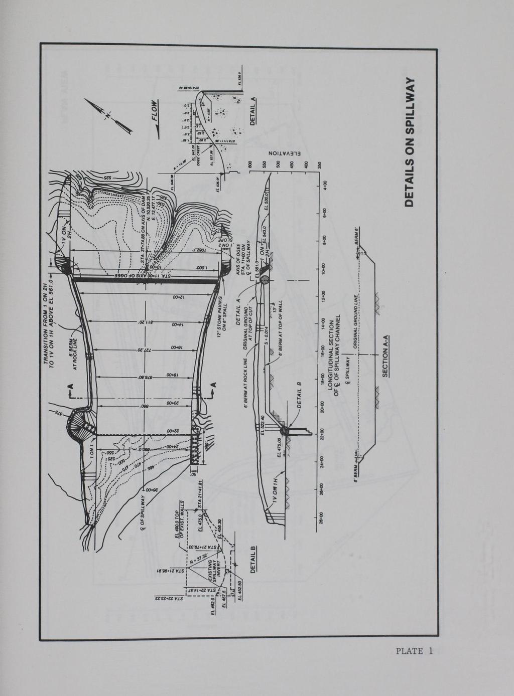
|
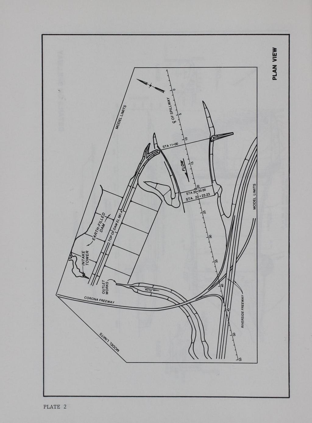
|
- Erika Ferguson
- 5 years ago
- Views:
Transcription

1 0 S -C Property of the United StatN Government. HL TECHNICAL REPORT HL MODEL STUDY OF PRADO FLOOD-CONTROL DAM Hydraulic Model Investigation by John F. George Hydraulics Laboratory DEPARTMENT OF THE ARMY Waterways Experiment Station, Corps of Engineers 3909 Halls Ferry Road, Vicksburg, Mississippi VICI Nlll' MAP ' 0 0 lo.., I l ~--- September 1989 Final Report Approved For Pu blic Release; Distribution Unlimited R ::::'-..:.."'"'~"""". - "l,-, Us AR.. ~'{, ,' --~:lvays. J, ~ ' ' -,,,_ -- r- - - E,.r......_... I..._#, VICKSBUnG, tliississippi -~.-'!::),... LI...,..,Ar:-y Prepared tor US Army Engineer District, Los Angeles Los Angeles, California

2 Destroy this report when no longer needed. Do not return it to the originator. The findings in this report are not to be construed as an official Department of the Army position unless so designated by other authorized documents. The contents of this report are not to be used for advertising, publication, or promotional purposes. Citation of trade names does not constitute an official endorsement or approval of the use of such commercial products.

3 Unclassified SECURITY CLASSIFICATION OF THIS PAGE 1 a. REPORT SECURITY CLASSIFICATION Unclassified REPORT DOCUMENTATION PAGE 1 b RESTRICTIVE MARKINGS Form Approved OMB No a. SECURITY CLASSIFICATION AUTHORIT'f 3 DISTRIBUTION I AVAILABILITY OF REPORT 2b. DECLASSIFICATION I DOWNGRADING SCHEDULE Approved for public release; distribution unlimited. 4 PERFORMING ORGANIZATION REPORT NUMBER{S) 5. MONITORING ORGANIZATION REPORT NUMBER{$) Technical Report HL a. NAXE OF PERFORMING ORGANIZATION 6b. OFFICE SYMBOL 7a. NAME OF MONITORING ORGANIZATION US EWES (If applicable) Hydraulics Laboratory CEWES-HS-L 6c. ADDRESS (City, State, and ZIP Code) 7b. ADDRESS (City, State, and ZIP Code) 3909 Halls Ferry Road Vicksburg, MS Sa. NAME OF FUNDING I SPONSORING Bb. OFFICE SYMBOL 9. PROCUREMENT INSTRUMENT IDENTIFICATION NUMBER ORGANIZATION (If applicable) USAED, Los Angeles 8c. ADDRESS (City, State, and ZIP Code) 10 SOURCE OF FUNDING NUMBERS PROGRAM PROJECT TASK WORK UNIT PO Box 2711 ELEMENT NO. NO. NO. ACCESSION NO. Los Angeles, CA TITLE (Include Security Classification) Model Study of Prado Flood-Control Dam; Hydraulic Model Investi~ation 12. PERSONAL AUTHOR{S) George, John F. 13a. TYPE OF REPORT 13b. TIME COVERED 14 DATE OF REPORT (Year, Month, Day) 15. PAGE COUNT Final report FROM TO September SUPPLEMENTARY NOTATION Available from National Technical Information Service, 5285 Port VA Royal Road, Springfield, 17. COSA Tl CODES 18. SUBJECT TERMS (Continue on reverse if necessary and identify by block number) FIELD GROUP SUB-GROUP Hydraulic models Prado Dam 19. ABSTRACT (Continue on reverse if necessary and identify by block number) Santa Anna River Spillways Tes~s were conducted on a 1:80-scale model of the Prado Dam and spillway to determine the adequacy of proposed modifications to the existing structure to convey the revised design flow of 615,000 cfs. These modifications were to serve as an interim solution until decisions were made either to make major design modifications to the existing structure or construct a new structure upstream of Prado Dam that would control downstream flow releases. Unsymmetrical approach conditions to the spillway resulted in poor flow conditions at the left and right abutments at the weir, which caused a reduction in the effective length of the weir. Test results indicated that installing long approach walls on either side improved flow conditions at the weir, but did not significantly increase the capacity 20 DISTRIBUTION I AVAILABILITY OF ABSTRACT 21 ABSTRACT SECURITY CLASSIFICATION lxj UNCLASSIFIED/UNLIMITED 0 SAME AS RPT 0 OTIC USERS Unclassified 22a NAME OF RESPONSIBLE INDIVIDUAL (Continued) 22b TELEPHONE (Include Area Code) 22c OFFICE SYMBOL DO Form 1473, JUN 86 Prevtous edtttons are obsolete SECURITY CLASSIFICATION OF TH I S PA GE Unclassified

4 Unclassified SECURITY C!.ASSoFICA TION OF n t~ PAr.~ 19. ABSTRACT (Continued). of the spillway or improve flow conditions on the spillway. Therefore, dikes were installed on the left and right abutments to streamline approach conditions to the spillway, thereby improving flow conditions at the weir. 'v With design conditions the water surface exceeded proposed wall heights along the spillway. Additional wall height was obtained by paving a small berm and existing topography along each side of the spillway. A wall having a warped surface also had to be placed on top of the berm at the downstream end of the spillway chute to redirect any flow that overtopped the paved berm back onto the spillway. Flow conditions downstream of the flip bucket were unsatisfactory, with large standing waves present in the exit channel and a large eddy present between the spillway exit channel and the earth dam. Maximum velocities of 11 fps were recorded along the toe of the dam with a discharge of 400,000 cfs. Due to the erodibility of the material in the exit channel, the potential is high for severe scour to occur in these areas with a major tlood event. No noticeable backwater effects were observed from the constricted bridge crossing and highways just downstream of the spillway. The design discharge of 615,000 cfs simply submerges these structures. Unclassified SECURITY CLASSIFICA TION OF Tl-l 'i PAG E
. The study was conducted by personnel of the Hydraulics Laboratory (HL), US Army Engineer Waterways Experiment Station (WES), during the period January 1981 to June 1983.")
5 PREFACE The model investigation reported herein was authorized by the US Army Engineer Division, South Pacific (SPD), on 12 March 1981, at the request of the US Army Engineer District, Los Angeles (SPL). The study was conducted by personnel of the Hydraulics Laboratory (HL), US Army Engineer Waterways Experiment Station (WES), during the period January 1981 to June All studies were conducted under the direction of Messrs. H. B. Simmons and F. L. Herrmann, Jr., former and present Chiefs, HL; and J. L. Grace, Jr., Chief of the Hydraulic Structures Division. The tests were conducted by Messrs. J. F. George, J. H. Riley, and C. L. Dent, all of the Locks and Conduits Branch, under the supervision of Mr. G. A. Pickering, Chief of the Locks and Conduits Branch. This report was prepared by Mr. George and eaited by Mrs. Marsha Gay, Information Technology Laboratory, WES. Messrs. S. B. Powell, Headquarters, US Army Corps of Engineers; Ted Albrecht, SPD, and Bob Koplin, SPL, visited WES during the study to discuss test results and to correlate these results with concurrent design work. Acting Commander and Director of WES during preparation of this report was LTC Jack R. Stephens, EN. Technical Director was Dr. Robert W. Whalin. 1

6 CONTENTS PREFACE CONVERSION FACTORS, NON-S! TO SI (METRIC) UNITS. PART PART PART PART ()F ~J\~lJit~E~Jr. I: INTRODUCTION. Tqe Prototype Project Design Flood Purpose of Model Study II: THE MODEL. Description Model Appurtenances Scale Relations.... III: TESTS AND RESULTS. Approach Area and Spillway. Exit ~llcllllle!jl IV: PHOTOS 1-13 PLATES 1-15 CONCLUSIONS AND RECOMMENDATIONS. Conclusions Recommended Design Page
 square feet square miles by 4,046.873 1,233.489 0.02831685 0.3048 2.54 1.609347 0.09290304 2.")
7 CONVERSION FACTORS, NON-SI TO SI (METRIC) UNITS OF MEASUREMENT Non-SI units of measurement used in this report can be converted to SI (metric) units as follows: Multiply acres acre-feet cubic feet feet inches miles (US statute) square feet square miles by 4, , To Obtain square metres cubic metres cubic metres metres centimetres kilometres square metres square kilometres 3
 ' v SAN DIEGO CO. Oceanside VICINITY MAP SCALE 10 0 10 20 Ml Figure 1.")
8 us ~~ LOS ANGELES CO >-I.Y US60 I \ I I \ Claremont -...o,..---: 1 :":":N~TS~T ~ 1 0 San ~'1) Bernardi no Santa Catalina Is. RIVERSIDE.. CO. ""'\ SANTA ANA RNER ORANGE co -, I ') ' v SAN DIEGO CO. Oceanside VICINITY MAP SCALE Ml Figure 1. Vicinity map 4
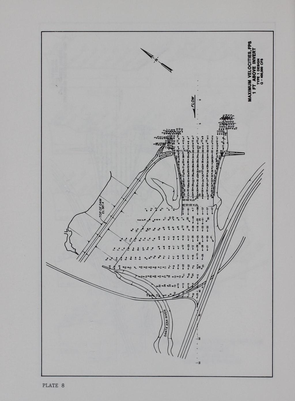
.")
9 MODEL STUDY OF PRADO FLOOD-CONTROL DAM Hydraulic Model Investigation PART I: INTRODUCTION The Prototype 1. The Prado Dam and spillway is located on the Santa Ana River about 30 miles* from the river's mouth at the Pacific Ocean and in the upper extremity of Santa Ana Canyon (Figure 1). The tributary drainage system upstream of the dam, comprising an area of 2,255 square miles of mountains, foothills, and valley floor, is situated in San Bernardino, Riverside, and Los Angeles Counties. The elevation of the drainage area varies from 470** at the reservoir to 11,485 at San Gorgonio Peak in the San Bernardino Mountains. 2. The spillway (Plate 1) consists of a concrete ogee-type structure that is 13 ft high with a crest length of 1,000 ft at el 543. The spillway is 1,100 ft long and converges to a 660-ft width with a flip bucket at the downstream end. 3. The rolled earth-filled dam (Plate 2), having a crest length of 2,280 ft at el 566 and a maximum height of 105 ft above streambed, forms a reservoir with an area of 10,830 acres and a corresponding capacity of 423,000 acre-feet at the top of the dam. 4. The outlet structure (Plate 2), which is located within the earthfilled dam near the right abutment, consists of an intake tower with two gated conduits with gate sills at el 460, and two ungated circular conduit bypasses, 5.5 ft in diameter with the entrance invert at el 462. The combined maximum capacity of the conduits is 17,300 cfs with the pool stage at spillway crest. Project Design Flood 5. The spillway was originally designed for a discharge capacity of * A table of factors for converting non-s! units of measurement to SI (metric) units is presented on page 3. ** All elevations (el) cited herein are in feet referred to the National Geodetic Vertical Datum (NGVD). 5

10 178,000 cfs upon its completion in Due to increases in reservoir and spillway design rainfalls as a result of revised hydrologic analyses, and the increase in runoff to the reservoir due to unanticipated urbanization over much of the valley, the spillway design discharge was increased to 615,000 cfs. Purpose of Model Study 6. Modifications proposed for the existing dam and spillway were to serve as an interim solution until decisions were made either to construct a new dam upstream of Prado Dam or make major modifications at Prado Dam in order to control releases from a major flood event. The initial plan of improvements consisted of raising the dam embankment from el 560 to el and spillway walls of the existing structure to safely pass the Probable Maximum Flood. A model study was considered necessary to verify the adequacy of the existing spillway design along with proposed modifications and develop, if necessary 1 a design that would provide satisfactory flow conditions throughout the structure. Specifically, the model study was to a... b. c... Document flow conditions along the spillway. Determine flow conditions in the downstream vicinity of the spillway. Evaluate backwater conditions resulting from the constricted bridge crossings and highways just downstream of the spillway. 6
 reproduced approximately 1,500 ft of approach channel to the spillway, the spillway (Photo 1) and dam, the outlet works stilling basin and intake tower (Photo")
11 PART II: THE MODEL Description 7. The 1:80-scale model (Figure 2, Plate 2) reproduced approximately 1,500 ft of approach channel to the spillway, the spillway (Photo 1) and dam, the outlet works stilling basin and intake tower (Photo 2), and approximately 3,400 ft of exit channel. The spillway was constructed of sheet metal, and the intake tower and outlet works stilling basin were constructed of transparent plastic. The approach and exit channels and dam were molded in sand and cement mortar to sheet metal templates. Model Appurtenances 8. Water used in the operation of the model was supplied by a circulating system. Discharges were measured with venturi meters installed in the flow lines and were baffled before entering the model. Velocities were measured with pitot tubes that were mounted to permit measurement of flow from any direction and at any depth. Water-surface elevations were measured with point gages. Different designs and various flow conditions were recorded photographically. Scale Relations 9. The accepted equations of hydraulic similitude, based on the Froude criteria, were used to express mathematical relations between the dimensions and hydraulic quantities of the model and prototype. General relations for the transference of model data to prototype equivalents are presented as follows: Characteristic Length Area Velocity Dimension* LR ~ - L2 R VR - 11/2 R Time TR = 11/2 R Discharge QR - ti/2 Scale Relations 1:80 1:6,400 1: : :57,243 * Dimensions are in terms of length. 7
12 ... a. Looking upstream a,.. I b. Looking downstream Figure 2. General view of 1:80-scale model 8

13 Model measurements of discharge, water-surface elevations, and velocities can be transferred quantitatively to prototype by the scale relations. 9

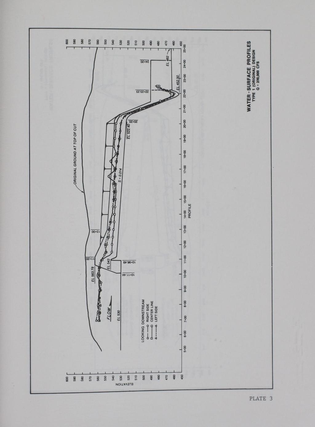
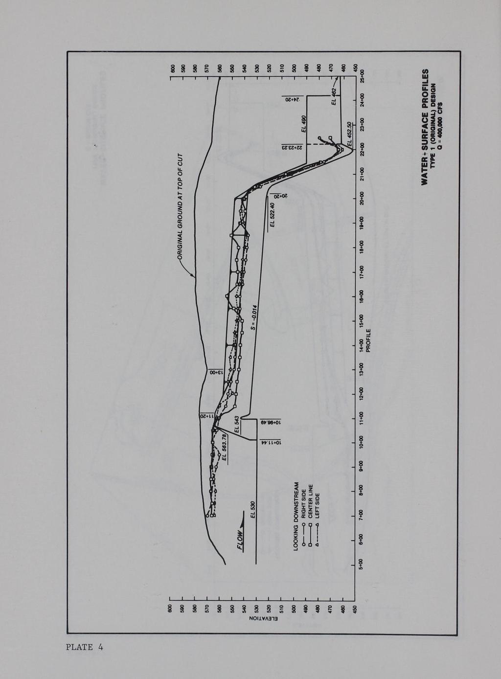
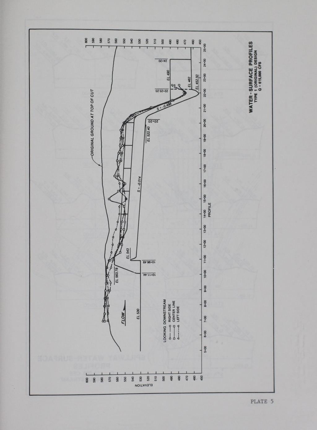
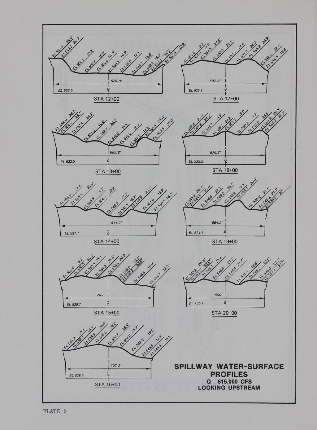
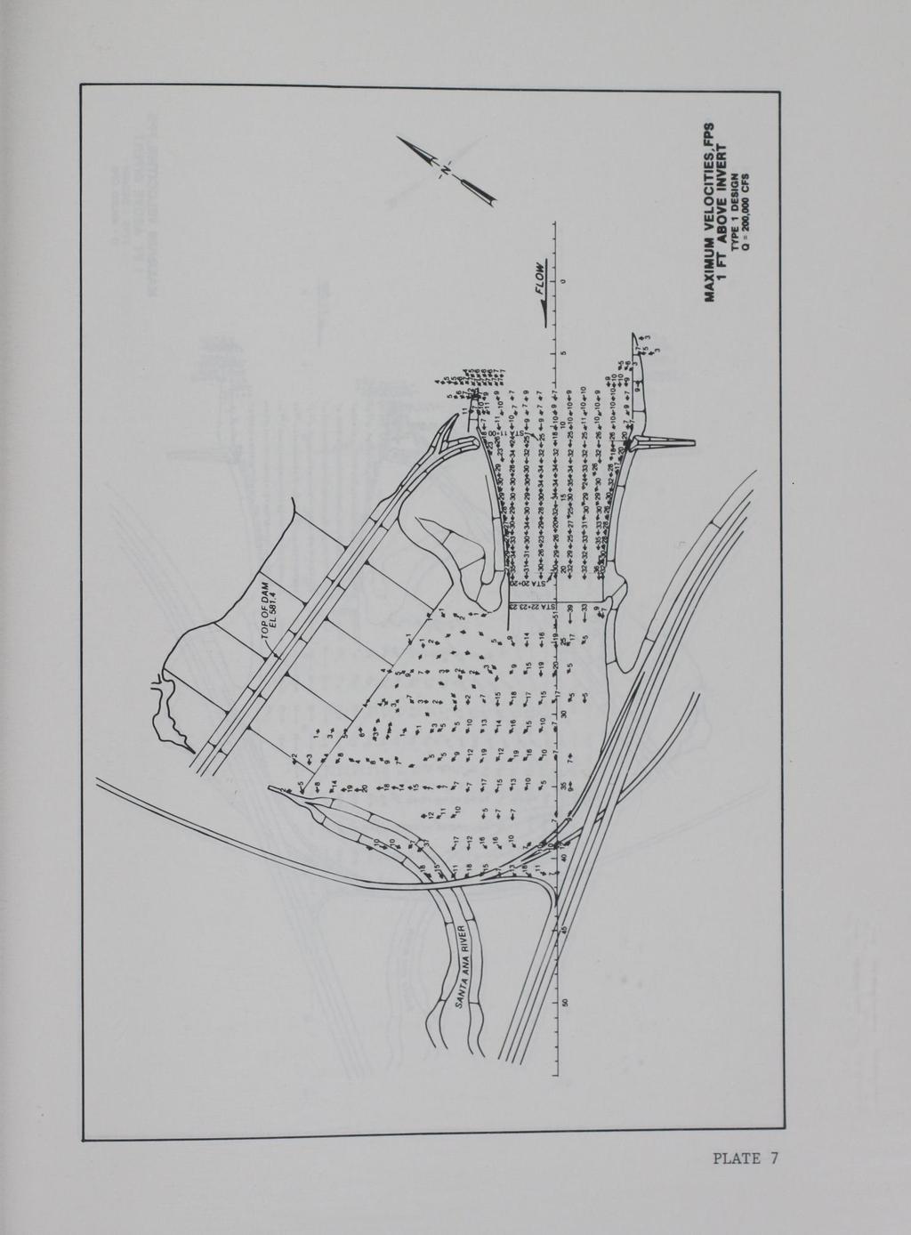
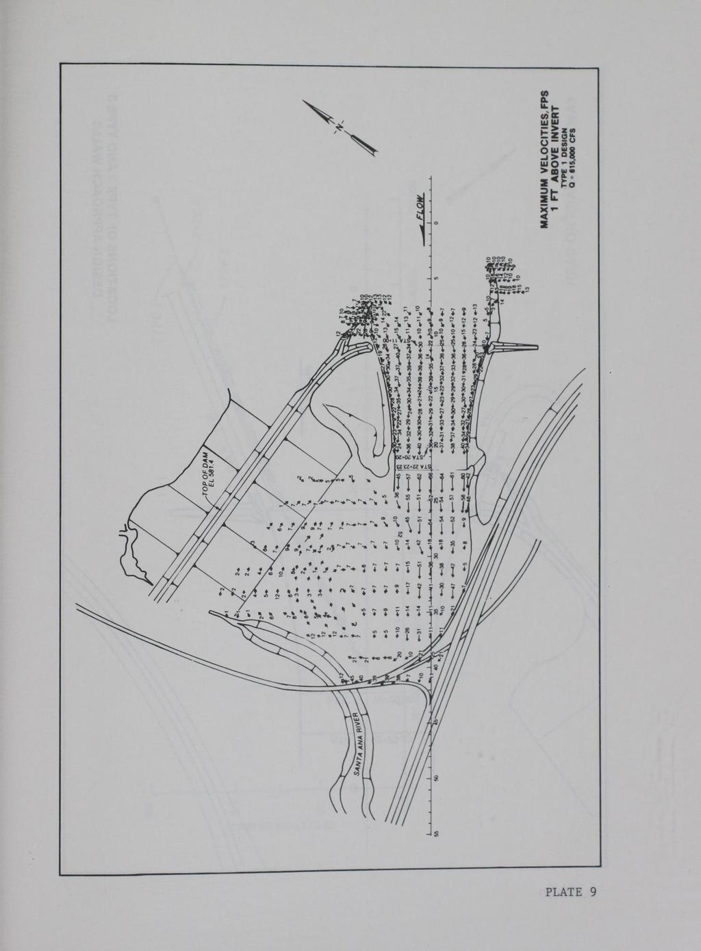
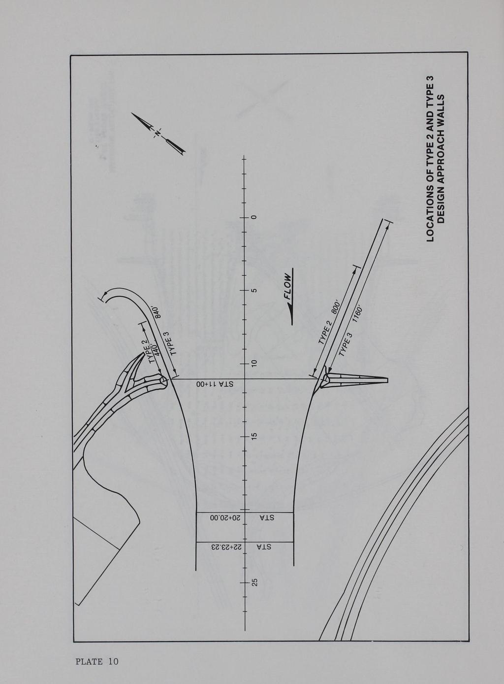
14 PART III: TESTS AND RESULTS 10. Tests were conducted to determine approach conditions to the spillway, the hydraulic performance of the spillway, and general flow conditions in the exit channel for various discharges. Approach Area and Spillway 11. Flow conditions observed in the approach to the spillway were found to be unsatisfactory with discharges Q of 200,000, 400,000, and 615,000 cfs (design discharge). The left and right IV on 2H slopes upstream of the weir created unsymmetrical approach conditions to the spillway as shown in Photo 3. The location of the slopes in the approach forced flow around the slopes (Photos 4 and 5), which resulted in poor flow conditions approaching the spillway and reduced the effective length of the weir. 12. Approach conditions, along with the converging spillway design, caused large standing waves to form on the spillway. These standing waves exceeded proposed spillway wall heights with the design discharge of 615,000 cfs. Water-surface profiles along the spillway (Plates 3-5) along with photographs of flow conditions in this vicinity (Photo 6) indicated the nonuniformity of flow distribution on the spillway with the higher range of discharges. Water-surface profiles recorded perpendicular to the center line of the spillway with the design discharge (Plate 6) further indicate unsymmetrical flow conditions along the spillway. Velocities measured in the approach, along the spillway, and in the exit channel are shown in Plates Approach walls of different lengths (types 2 and 3 shown in Plate 10) were added to the existing walls in an effort to increase the efficiency of the spillway and reduce the height of the standing waves on the spillway. Very long approach walls were installed to produce optimum streamline approach conditions to the spillway. A reduction in height of the standing waves was observed with the additional wall lengths, but little difference in the head on the spillway was noted (Plate 11). These data indicated the extended approach walls resulted in little improvement in capacity and flow conditions along the spillway. 14. The left and right abutments of the spillway were modified in an attempt to improve approach conditions at the spillway. These modifications 10

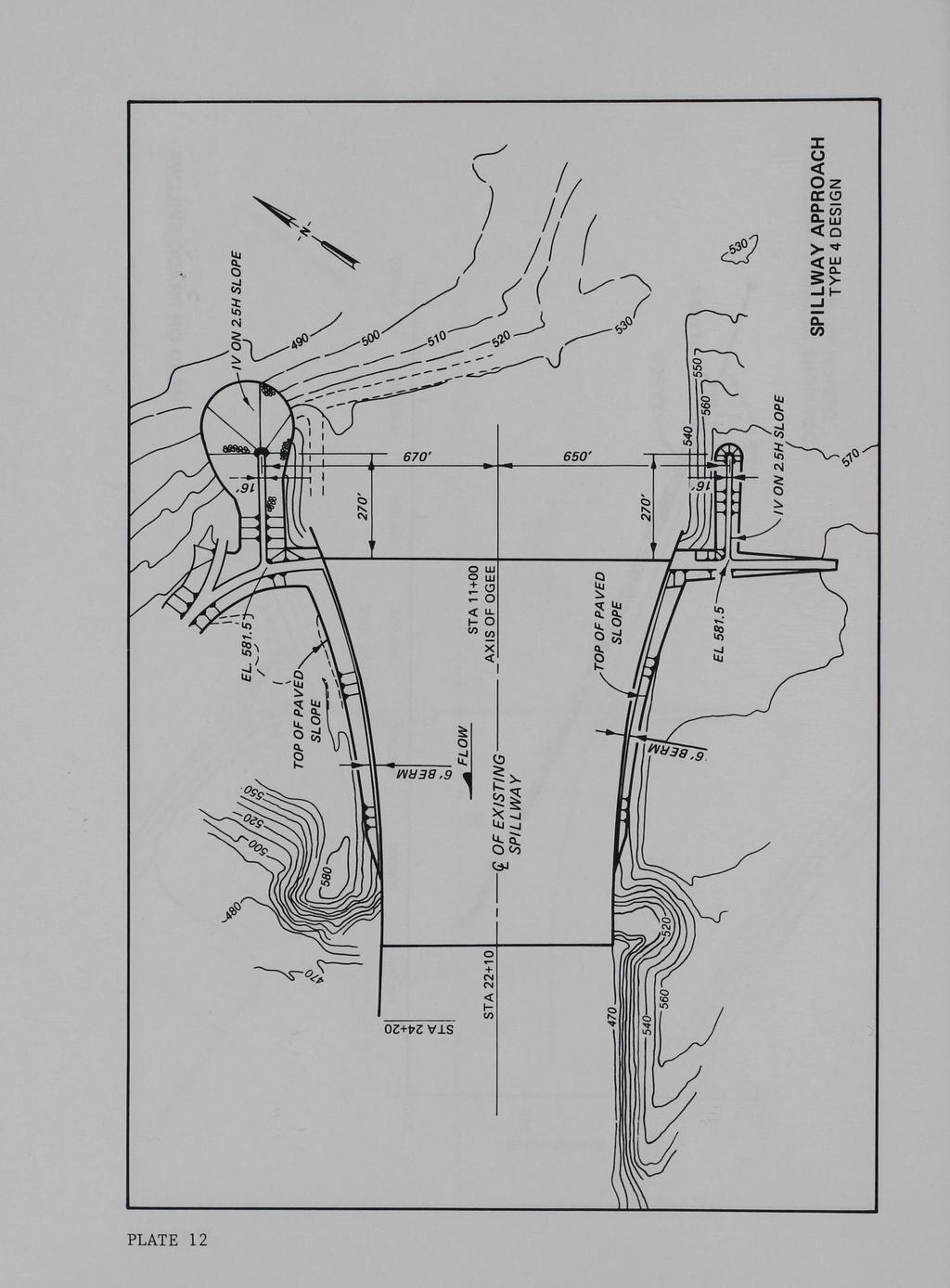
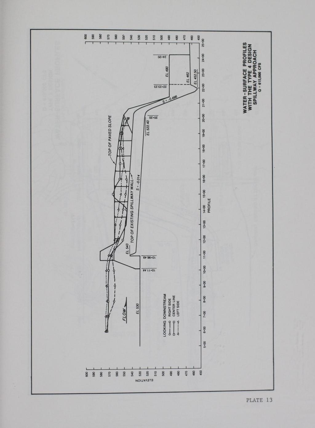
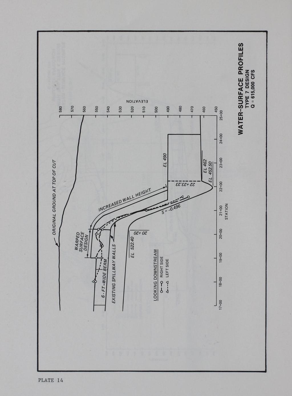
15 included the addition of dikes extended upstream from the abutments and parallel to the center line of the spillway, which was designated the type 4 design spillway approach. Details of the configuration and location of dikes with respect to the spillway are shown in Photos 7 and 8 and Plate With the type 4 design spillway approach installed, flow conditions were satisfactory at the left and right abutments to the spillway. With the design discharge, the majority of flow around the left dike (looking downstream) was directed along the left spillway wall (Photo 7b). Flow conditions around the right dike were considerably different, as compared with the left dike, due to the direction of flow approaching the spillway. A significant amount of flow approaches the spillway from the right side due to the alignment of the spillway with respect to the reservoir. With the original design, the existing topography caused the flow to make a sharp turn around the right abutment just upstream of the spillway. Even though this same condition existed with the right dike in place (Photo 8), a definite improvement in approach conditions was noted at the right abutment and along the right side of the spillway. Water-surface profiles along the spillway (Plate 13) also indicated an improvement in flow conditions along the left and right spillway walls. A slight reduction in head on the spillway was noted with this design as compared to the type 1 design spillway approach (Plate 11). 16. It was observed that as the flow increased on the spillway, the water surface exceeded proposed wall heights and a portion of the flow rode along on top of the berm and entered the exit channel on the outside of the walls in the vicinity of the flip bucket. This could cause possible scour to develop along the wall's footings, resulting in potential failure of the walls. 17. Tests were conducted with walls of different lengths placed on top of the 6-ft-wide berm at the downstream end of the spillway chute in an effort to redirect flow back onto the spillway when the water surface exceeds the existing spillway walls. Wall lengths ranging from 40 to 120 ft were tested with a discharge of 615,000 cfs. A 120-ft-long wall having a warped surface (type 7 design berm wall) provided the best results in redirecting the majority of flow back onto the spillway. The wall heights along both sides of the spillway were also increased by paving the berm and existing topography. Flow conditions with the 120-ft-long wall modification and increased wall 11

16 heights are shown in Photo 9. Water-surface profiles in this area are provided in Plate No additional tests were conducted to further improve flow conditions on the spillway. The standing waves that were present for the various discharges observed were caused by the convergence of the spillway walls. Flow conditions could be improved, but this would entail major modifications to the spillway itself. Because this was not in the scope of testing in this investigation, efforts were directed towards documentation of flow conditions in the exit channel. Exit Channel 19. With the original design, flow conditions observed in the exit channel were unsatisfactory, with significant standing waves present with the design discharge (Photo 10). A large eddy was observed between the spillway exit channel and the earth dam (Photo 11) with velocities ranging up to 11 fps along the toe of the dam with a discharge of 400,000 cfs (Plate 8). The maximum velocities recorded along the dam were caused by the large eddy and wave action (Photo 12) present in that vicinity. Velocities measured in the exit channel are provided in Plates The large eddy that was observed between the exit channel and the earth dam created a significant differential on the right wall at the downstream end of the spillway. The slower velocity and direction of flow created by the eddy resulted in a buildup of flow on the back side of the wall with high velocities and a much lower water surface on the inside of the wall where the flip bucket is located, as shown in Photo 10c. 21. Tests were conducted to determine the effects on general flow patterns in the exit channel if the right wall had failed. The eddy, which was present on the right side of the exit channel with all discharges observed, concentrated more of the flow along the left side of the exit channel without the wall in place, resulting in even worse flow conditions in the exit channel than previously observed (compare Photos 10c and 13). 22. Little dissipation occurred downstream of the flip bucket for the discharges observed. No noticeable backwater effects were present due to the bridge constrictions and highways located in the exit channel. The flow 12

17 simply rode over and through these areas without having any significant impact such as backwater effects developing. 13

18 PART IV: CONCLUSIONS AND RECOMMENDATIONS Conclusions 23. Tests were conducted to determine if the proposed modifications to the existing dam and spillway would be adequate to provide the necessary protection~ from a major flood event. Test results indicated that with certain modifications, the spillway would perform satisfactorily for the interim solution. 24. Unsymmetrical approach conditions to the spillway along with existing sloping topography caused contraction of flow at the abutments, which reduced the effective length of the spillway weir. Very long approach walls installed upstream of the weir significantly improved flow conditions to the spillway; however, this modification had little effect on reducing the head on the spillway. The long approach walls resulted in little improvement in spillway capacity and flow conditions along the spillway. 25. Dikes extending upstream from the left and right abutments to the spillway did improve flow conditions at the spillway weir. This resulted in increasing the effective length of the weir to a degree, but had little effect on significantly increasing the capacity of the spillway. 26. Large standing waves were present on the spillway due to approach conditions and the converging spillway design. These standing waves exceeded spillway wall heights proposed in the interim solution design. With the installation of the dikes in the spillway approach, a reduction in wave heights was noted, but additional wall heights were required to contain design flows within the limits of the spillway. 27. When the water surface exceeded the existing wall heights, the flow rode along on top of the berm and entered the exit channel on the outside of the downstream training walls. This could result in local scour along the bottom of the walls, possibly causing the walls to fail. A 120-ft-long wall having a warped surface placed on top of the berm at the downstream end of the spillway chute provided the best results in redirecting the flow back onto the spillway. Additional wall height was obtained by paving a small berm and existing topography along each side of the spillway. 28. No additional tests to try to reduce the height of the standing waves present were conducted, because these waves were created by the 14

19 convergence of the spillway walls. Major design changes to the existing spillway would have to be undertaken to reduce the heights of the standing waves. Because this was not in the scope of testing in this investigation, efforts were directed towards documentation of flow conditions in the exit channel. 29. Large standing waves were present just downstream of the flip bucket, and a large eddy was observed between the spillway exit channel and the earth dam with the higher range of discharges. Maximum recorded velocities along the toe of the dam were approximately 11 fps and were observed with a discharge of 400,000 cfs. Due to the magnitude of velocities measured in this area, riprap protection should be considered along the toe of the dam. 30. With the higher discharges, little, if any, dissipation occurred downstream of the flip bucket. Due to the erodible material in the exit channel, which was not reproduced in the model, severe scour would probably occur resulting in possible failure of the bridges and significant damage to the highways just downstream of the structure. No noticeable backwater effects were observed from the constricted bridge crossings and highways just downstream of the spillway. The higher flow simply rode over, around, and through these areas. 31. Because of the eddy present between the exit channel and spillway, a large differential in the water surface was present between the inside and outside of the right wall at the downstream end of the spillway. This was caused by the buildup of flow on the outside of the wall due to the direction of flow from the eddy and the high velocities and low water surface present in the flip bucket on the inside of the wall. Because of this differential, tests were conducted to determine the effects on flow conditions downstream of the structure if the right wall failed. Test results indicated that the eddy, present on the right side of the spillway, forced the flow from the spillway along the left side of the exit channel. This resulted in even worse flow conditions present in the exit channel than previously observed. Recommended Design 32. Based on test results the modifications required t o provide adequate protection during a major flood event consisted of (a) placing dikes immediately upstream of the left and right abutments of the spillway, (b) increasing 15

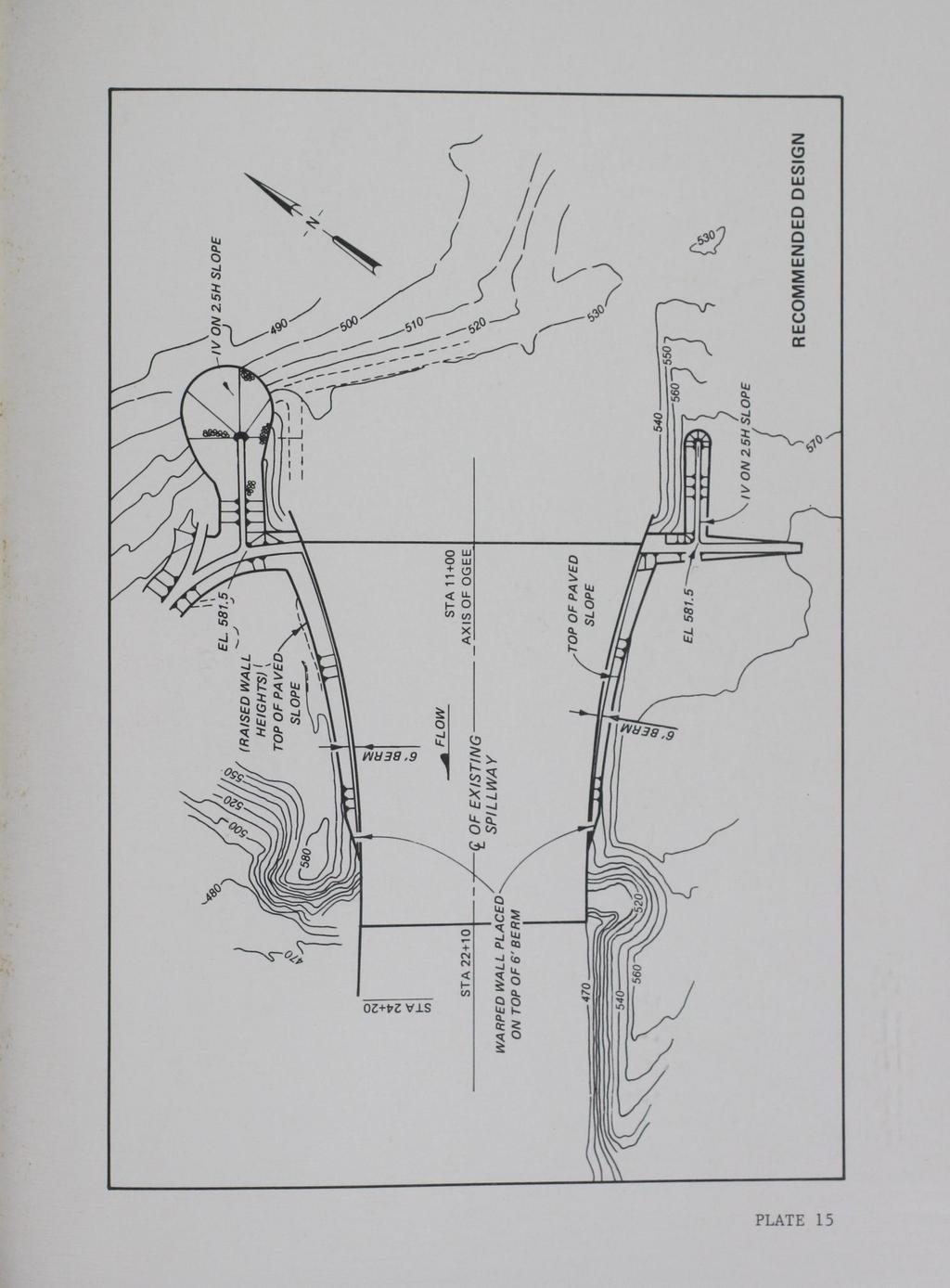
20 the heights of the spillway walls using existing topography, and (c) constructing walls on top of the 6-ft-wide berm at the downstream end of the spillway. These modifications, shown in Plate 15, should provide the protection needed for the interim solution. However, major changes such as increasing the spillway width would be required to improve flow conditions along the spillway and in the exit channel. 16

21 H ~-, a, Photo 1. Spillway and flip bucket ~~JuTLET WORKS STILLING B~SIN Photo 2. Intake tower and outlet works through dam.f.l.litup INTAKE TOWER
22 a. Q - 200,000 cfs b. Q - 400,000 cfs c. Q = 615,000 cfs Photo 3. Flow conditions in spillway approach. Confetti illustrates surface flow patterns (exposure time 18 sec prototype)
23 a. Q ~ 200,000 cfs b. Q - 400,000 cfs c. Q = 615,000 cfs Photo 4. Flow conditions (with dye) at left side of approach to spillway
 at right side of approach to spillway")
24 a. Q - 200,000 cfs b. Q - 400,000 cfs c. Q = 615,000 cfs Photo 5. Flow conditions (with dye) at right side of approach to spillway
25 a. Q = 200,000 cfs b. Q = 400,000 cfs c. Q = 615,000 Photo 6. Flow conditions on spillway
 Photo 7.")
26 a. Dry bed b. Flow conditions around left dike. Confetti accents surface flow patterns. Q = 615,000 cfs (exposure time 9 sec prototype) Photo 7. Left dike (type 4 design spillway approach)
 Photo 8.")
27 a. Dry bed b. Flow conditions around right dike. Confetti accents surface flow patterns. Q = 615,000 cfs (exposure time 9 sec prototype) Photo 8. Right dike (type 4 design spillway approach)
")
28 Photo 9. Warped-surface modification (between sta and sta 20+20) recommended on top of existing wall. Q = 615,000 cfs

29 a. Q - 200,000 cfs b. Q - 400,000 cfs Photo 10. c. Q = 615,000 cfs Flow conditions downstream of type 1 design spillway
30 ~. a. Q - 200,000 cfs b. Q - 400,000 cfs c. Q = 615,000 cfs Photo 11. General view of flow conditions in the exit channel. Confetti accents surface flow patterns (exposure time 18 sec prototype)

31 Photo 12. Flow conditions along toe of dam. Q - 400,000 cfs Photo 13. Flow condition with right wall removed downstream of flip bucket. Q = 615,000 cfs
32
33
34
35
36
37
38
39
40
41

42
43
44
45
46
PROFILE OF SACRAMENTO RIVER, FREEPORT TO VERONA, CALIFORNIA,
 PROFILE OF SACRAMENTO RIVER, FREEPORT TO VERONA, CALIFORNIA, FLOOD OF FEBRUARY 1986 By J.C. Blodgett and J.B. Lucas U.S. GEOLOGICAL SURVEY Open-File Report 88-82 CO CM I m r-h CM Sacramento, California
Greenup Lock Filling and Emptying System Study
 Fourth LACCEI International Latin American and Caribbean Conference for Engineering and Technology (LACCET 2006) Breaking Frontiers and Barriers in Engineering: Education, Research and Practice 21-23 June
CLAIBORNE LOCK AND DAM PERTINENT DATA
 CLAIBORNE LOCK AND DAM PERTINENT DATA GENERAL Location Clarke, Monroe, & Wilcox Counties, Alabama; Alabama River, river mile 72.5 Drainage area Millers Ferry to Claiborne sq. mi. 836 Total drainage area
USING A LABYRINTH WEIR TO INCREASE HYDRAULIC CAPACITY. Dustin Mortensen, P.E. 1 Jake Eckersley, P.E. 1
 USING A LABYRINTH WEIR TO INCREASE HYDRAULIC CAPACITY Dustin Mortensen, P.E. 1 Jake Eckersley, P.E. 1 Plum Creek Floodwater Retarding Structure No. 6 is located in an area of Kyle, Texas, that is currently
STRUCTURE S-65 PURPOSE SPILLWAY OPERATION
 STRUCTURE S-65 This structure is a reinforced concrete, gated spillway with discharge controlled by three cable operated, vertical lift gates, and a reinforced concrete lock structure with two pairs of
HYDRAULIC JUMP AND WEIR FLOW
 HYDRAULIC JUMP AND WEIR FLOW 1 Condition for formation of hydraulic jump When depth of flow is forced to change from a supercritical depth to a subcritical depth Or Froude number decreases from greater
The Hydraulic Design of an Arced Labyrinth Weir at Isabella Dam
 Utah State University DigitalCommons@USU International Symposium on Hydraulic Structures Jun 28th, 1:30 PM The Hydraulic Design of an Arced Labyrinth Weir at Isabella Dam E. A. Thompson Sacramento District
Technical Report Culvert A Hydraulic Analysis
 DATE: November 3, 2011 Technical Report Culvert A Hydraulic Analysis TO: FROM: RE: Jim Reiser, P.E. Project Manager Parsons Brinckerhoff, Inc. Kurt Killian, P.E., CFM Parsons Brinckerhoff, Inc. Design
CHAPTER 4 SPALDING COUNTY, GEORGIA 4.0 CULVERT DESIGN
 SPALDING COUNTY, GEORGIA CHAPTER 4 4.0 CULVERT DESIGN... 4-1 4.1 INTRODUCTION... 4-1 4.2 SYMBOLS AND DEFINITIONS... 4-1 4.3 ENGINEERING DESIGN CRITERIA... 4-2 4.3.1 FREQUENCY FLOOD... 4-2 4.3.2 VELOCITY
APPENDIX A STRUCTURE DESCRIPTIONS AND RATING CURVES
 3 4 5 6 7 8 9 0 3 APPENDIX A STRUCTURE DESCRIPTIONS AND RATING CURVES Kissimmee River Vol December 005 Version Draft 4 3 4 5 6 7 8 9 0 3 4 5 6 7 8 9 0 3 4 5 6 7 8 9 30 3 3 33 34 35 36 37 38 39 40 4 4 43
Sediment Basin 7E-12. Design Manual Chapter 7 - Erosion and Sediment Control 7E - Design Information for ESC Measures BENEFITS.
 7E-12 Design Manual Chapter 7 - Erosion and Sediment Control 7E - Design Information for ESC Measures Sediment Basin BENEFITS Flow Control Erosion Control Sediment Control Runoff Reduction Flow Diversion
OFFICE OF STRUCTURES MANUAL FOR HYDROLOGIC AND HYDRAULIC DESIGN CHAPTER 11 APPENDIX B TIDEROUT 2 USERS MANUAL
 OFFICE OF STRUCTURES MANUAL FOR HYDROLOGIC AND HYDRAULIC DESIGN CHAPTER 11 APPENDIX B TIDEROUT 2 USERS MANUAL APRIL 2011 APRIL 2011 Page 1 Preface TIDEROUT 2, Build 1.22 dated June 29, 2006 is the current
General Information for Culvert Design
 Design Manual Chapter 2 - Stormwater 2E - Culvert Design 2E-1 General Information for Culvert Design A. Introduction A culvert is a conduit under an embankment that transports stormwater from one side
APPENDIX C VEGETATED EMERGENCY SPILLWAY. VERSION 1.0 March 1, 2011
 APPENDIX C VEGETATED EMERGENCY SPILLWAY VERSION 1.0 March 1, 2011 [NOTE: Could use a better photo more clearly showing the emergency spillway in the context of the dam.] SECTION C-1: DESCRIPTION OF PRACTICE
Plan B Dam Breach Assessment
 Plan B Dam Breach Assessment Introduction In support of the Local Sponsor permit applications to the states of Minnesota and North Dakota, a dam breach analysis for the Plan B alignment of the Fargo-Moorhead
CHAPTER 5 CULVERT DESIGN
 CHAPTER 5 CULVERT DESIGN HYDRAULICS OF CULVERTS There are two major types of culvert flow: 1) flow with inlet control, and 2) flow with outlet control. For each type, different factors and formulas are
APPENDIX B HYDRAULIC DESIGN DATA FOR CULVERTS
 TM 5-820-4/AFM 88-5, Chap 4 APPENDIX B HYDRAULIC DESIGN DATA FOR CULVERTS B-1. General. a. This appendix presents diagrams, charts, coefficients and related information useful in design of culverts. The
OLD RIVER LOW-SILL CONTROL STRUCTURE: DYNAMIC HYDRAULIC FORCES ACTING ON THE STILLING BASIN, SURVEY BOAT SAFETY, AND DEBRIS PASSAGE
 TA7 W34 no.iil-88-6 c.4 TECHNICAL REPORT HL-88-6 OLD RIVER LOW-SILL CONTROL STRUCTURE: DYNAMIC HYDRAULIC FORCES ACTING ON THE STILLING BASIN, SURVEY BOAT SAFETY, AND DEBRIS PASSAGE Hydraulic Model Investigation
Exercise (3): Open Channel Flow Rapidly Varied Flow
: Open Channel Flow Rapidly Varied Flow") Exercise (3): Open Channel Flow Rapidly Varied Flow 1) A hydraulic jump exists in a trapezoidal channel having a bed width of 7 m and side slope of 1:1. The flowing discharge is 25 m 3 /sec. Construct
Exercise (3): Open Channel Flow Rapidly Varied Flow 1) A hydraulic jump exists in a trapezoidal channel having a bed width of 7 m and side slope of 1:1. The flowing discharge is 25 m 3 /sec. Construct
Effect of Fluid Density and Temperature on Discharge Coefficient of Ogee Spillways Using Physical Models
 RESEARCH ARTICLE Effect of Fluid Density and Temperature on Discharge Coefficient of Ogee Spillways Using Physical Models M. SREENIVASULU REDDY 1 DR Y. RAMALINGA REDDY 2 Assistant Professor, School of
What Happens Downstream Stays Downstream, or Does It? Potential Failure Modes from Spillway Exit Flows
 What Happens Downstream Stays Downstream, or Does It? Potential Failure Modes from Spillway Exit Flows Gregory Richards, P.E., CFM, Gannett Fleming, Inc. Paul Schweiger, P.E., CFM, Gannett Fleming, Inc.
STRUCTURE 65-B PURPOSE SPILLWAY OPERATION
 STRUCTURE 65-B This structure is a reinforced concrete, gated spillway with discharge controlled by three cable operated vertical lift gates and a reinforced concrete lock structure with two pairs of sector
APPENDIX J HYDROLOGY AND WATER QUALITY
 APPENDIX J HYDROLOGY AND WATER QUALITY J-1 Technical Report on Airport Drainage, Northern Sector Airport and Ordinance Creek Watershed / Preliminary Creek Constructed Natural Channel Culvert J-2 Preliminary
COST EFFECTIVE STORAGE CAPACITY INCREASE FOR ALUMINA TAILINGS DISPOSAL AREA THROUGH SPILLWAY OPTIMISATION
 COST EFFECTIVE STORAGE CAPACITY INCREASE FOR ALUMINA TAILINGS DISPOSAL AREA THROUGH SPILLWAY OPTIMISATION Abstract Lonie I * Tailings and Dams, GHD Brisbane, QLD, Australia Queensland Alumina Limited operates
Designing Labyrinth Spillways for Less than Ideal Conditions Real World Application of Laboratory Design Methods
 Designing Labyrinth Spillways for Less than Ideal Conditions Real World Application of Laboratory Design Methods Gregory Richards, P.E., CFM, Gannett Fleming, Inc. Blake Tullis, Ph.D., Utah Water Research
Annex E Bridge Pier Protection Plan
 Annex E Bridge Pier Protection Plan Table E1 Bridge Types and Locations Table E2 Flow Conditions For River Sections Figure E1 Bridge Abutment Protection Figure E2 Bridge Pier Protection Figure E3 Central
HISTORY OF CONSTRUCTION
 HISTORY OF CONSTRUCTION CFR 257.73(c)(1) West Boiler Slag Pond Clifty Creek Plant Madison, Indiana October, 2016 Prepared for: Indiana Kentucky Electric Corporation Prepared by: American Electric Power
DAIVÕES DAM SPILLWAY: A NOVEL SOLUTION FOR THE STILLING BASIN
 DAIVÕES DAM SPILLWAY: A NOVEL SOLUTION FOR THE STILLING BASIN Elsa Alves *, Felix Hernando and Rafael Chacón * Laboratório Nacional de Engenharia Civil (LNEC) Av. do Brasil, 101, 1700-066 Lisboa, Portugal
HY-8 Version 7.2 Build Date January 17, Federal Highway Administration.
 HY-8 Version 7.2 Build Date January 17, 2012 Federal Highway Administration http://www.fhwa.dot.gov/engineering/hydraulics/software/hy8/index.cfm SIMPLE Simple to use Use for simple culverts and bridges
Scale Factor Study for 1:30 Local Scour Model
 Scale Factor Study for 1:30 Local Scour Model by Jeremy A. Sharp, Ronald E. Heath, Howard E. Park, and Tate O. McAlpin PURPOSE: This Coastal and Hydraulics Engineering Technical Note (CHETN) contains a
STRUCTURAL STABILITY ASSESSMENT
 STRUCTURAL STABILITY ASSESSMENT CFR 257.73(d) Fly Ash Reservoir II Cardinal Plant Brilliant, Ohio October, 2016 Prepared for: Cardinal Operating Company Cardinal Plant Brilliant, Ohio Prepared by: Geotechnical
EXAMPLES (OPEN-CHANNEL FLOW) AUTUMN 2018
 AUTUMN 2018") EXAMPLES (OPEN-CHANNEL FLOW) AUTUMN 2018 Normal and Critical Depths Q1. If the discharge in a channel of width 5 m is 20 m 3 s 1 and Manning s n is 0.02 m 1/3 s, find: (a) the normal depth and Froude number
EXAMPLES (OPEN-CHANNEL FLOW) AUTUMN 2018 Normal and Critical Depths Q1. If the discharge in a channel of width 5 m is 20 m 3 s 1 and Manning s n is 0.02 m 1/3 s, find: (a) the normal depth and Froude number
Folsom Dam Joint Federal Project Existing Spillway Modeling
 Hydraulic Laboratory Report HL-2009-02 Folsom Dam Joint Federal Project Existing Spillway Modeling Discharge Capacity Studies AMERICAN RIVER DIVISION CENTRAL VALLEY PROJECT MID-PACIFIC REGION U.S. Department
Huntington District. For More Information Contact (304)
") Zoar Levee & Diversion Dam are located in the Muskingum River Basin highlighted in green to left. The Muskingum River Basin is the site of Ohio s first multiple purpose water management and land conservation
Zoar Levee & Diversion Dam are located in the Muskingum River Basin highlighted in green to left. The Muskingum River Basin is the site of Ohio s first multiple purpose water management and land conservation
Scott Dam Spillway Comparing Physical Model Study Results
 Scott Dam Spillway Comparing Physical Model Study Results Darren Hinton, P.E., Ph.D., Seattle Laboratory Manager, Northwest Hydraulic Consultants, USA Brian Hughes, M.A.Sc., P.E., Principal, Northwest
LEHIGH UN IVERS ITY CIVIL ENGINEERING DEPARTMENT. Project Report No. 54. Prepared by. John R. Adam~;.,:~."; Arthur W. Brune and Stephen C.
 LEHIGH UN IVERS ITY CIVIL ENGINEERING DEPARTMENT FRITZ ENGINEERING laboratory HYDRAULIC AND SANITARY ENGINEERING DIVISION SPILLWAY MODEL STUDY FOR TWO LICK CREEK DAM Project Report No. 54 Prepared by John
Chapter 11. Culverts and Bridges Design Checklist for Culvert Design
 Yes No N/A Design Requirements I. GENERAL DESIGN GUIDELINES Chapter 11. Culverts and Bridges A. Culvert design is in accordance with the Culverts chapter of Volume 2 of the UDFCD Manual for additional
 Dam Modification Report Stingy Run Fly Ash Reservoir Appendix E Spillway System Design Calculations E1: Spillway/Energy Dissipater Design for 100-year Event CHE8273 8 September 4, 2014 Written by: CJW
EhhhhhhhhhhhhE EIIIIIIIEUML1N IJEJL3MLIDDDD0/ EllEIIhllllgI
 A7-R171 594 LOCK AND DAM I RED RIVER MATERNAY; HYDRAULIC. MODEL / INVESTIGATION(U) ARMY ENGINEER WATERWAYS EXPERIMENT STATION VICKSBURG MS HYDRAULICS LAS J E FOSTER ET AL. UNCLASSIFIED JUN 86 WES/TR/HL-86-6
APPENDIX A STRUCTURE DESCRIPTIONS AND RATING CURVES. Lake Okeechobee & EAA Vol 3 A-i December 2005 Version 1 Draft 4
 1 1 1 1 1 1 1 1 0 1 0 1 0 APPENDIX A STRUCTURE DESCRIPTIONS AND RATING CURVES Lake Okeechobee & EAA Vol A-i December 00 1 1 1 1 1 1 1 1 0 1 from the drainage area served, under a design head of. feet pool
OF HYRUM DAM AUXILIARY
 HYDRAULIC MODEL STUDY OF HYRUM DAM AUXILIARY LABYRINTH SPILLWAY May 7983 Engineering and Research Center S. Department of the Interior Bureau of Reclamation Division of Research Hydraulics Branch 7-2090
NUMERICAL AND PHYSICAL MODELING
 POINTE DU BOIS GENERATING STATION SPILLWAY REPLACEMENT PROJECT NUMERICAL AND PHYSICAL MODELING Kara Hurtig, Northwest Hydraulic Consultants, North Vancouver, BC, Canada David S. Brown, KGS Group, Winnipeg,
19.1 Problem: Maximum Discharge
 19.1 Problem: Maximum Discharge In partially full channel having an equilateral triangular cross section, the rate of discharge is Q = KAR/3 in which K is a constant, A flow area, R is the hydraulic mean
The Basics of Culvert and Inlet Design
 PDHonline Course C619 (8 PDH) The Basics of Culvert and Inlet Design Jerry D. Morrow, PE 2013 PDH Online PDH Center 5272 Meadow Estates Drive Fairfax, VA 22030 6658 Phone & Fax: 703 988 0088 www.pdhonline.org
APPENDIX C. Fluvial and Tidal Hydraulics Report
 APPENDIX C Fluvial and Tidal Hydraulics Report BUENA VISTA LAGOON ENHANCEMENT PROJECT FLUVIAL AND TIDAL HYDRAULICS ANALYSES Prepared for: SANDAG 401 B Street, Suite 800 San Diego, California 92101 Contact:
Spillway Design for Small Dams
 Spillway Design for Small Dams by David E. Fantina, PE Introduction: This course presents an overview of the features that go into the design of spillways for small dams. Small dams in this course refer
Components of a Barrage
 Components of a Barrage Definition The only difference between a weir and a barrage is of gates, that is the flow in barrage is regulated by gates and that in weirs, by its crest height. Barrages are costlier
ANSWERS TO QUESTIONS IN THE NOTES AUTUMN 2018
 ANSWERS TO QUESTIONS IN THE NOTES AUTUMN 2018 Section 1.2 Example. The discharge in a channel with bottom width 3 m is 12 m 3 s 1. If Manning s n is 0.013 m -1/3 s and the streamwise slope is 1 in 200,
Coastal and Hydraulics Laboratory
 ERDC/CHL TR-12-1 New Lock for Soo Locks and Dam, Model nvestigations during 26 21, Sault Ste. Marie, Michigan, St. Mary s River Hydraulic Model nvestigation John E. Hite, Jr. and Carlos Bislip-Morales
DESIGN OF BELL-MOUTH SPILLWAY AT BARVI DAM
 DESIGN OF BELL-MOUTH SPILLWAY AT BARVI DAM Akshay Haldankar 1, Mahesh Bhadra 2, Rahul Harad 3, Darpan Kapre 4, Dipali Patil 5 1,2,3,4 Under graduate,dept. of Civil Engineering, DRIEMS Neral. 5Assistant
Illinois State Water Survey
 Illinois State Water Survey HYDROLOGY DIVISION SWS Contract Report 508 COMPARISON OF 1987 AND 1989 BED PROFILE SURVEYS OF THE LOWER CACHE RIVER by Richard Allgire Office of Sediment and Wetland Studies
Broadly speaking, there are four different types of structures, each with its own particular function:
 3 The selection of structures 3.1 Introduction In selecting a suitable structure to measure or regulate the flow rate in open channels, all demands that will be made upon the structure should be listed.
Indiana LTAP Road Scholar Core Course #10 Culvert Drainage. Presented by Thomas T. Burke, Jr., PhD, PE Christopher B. Burke Engineering, Ltd.
 Indiana LTAP Road Scholar Core Course #10 Culvert Drainage Presented by Thomas T. Burke, Jr., PhD, PE Christopher B. Burke Engineering, Ltd. Objectives Review culvert shapes, end sections, and materials
TDLP INC. The Dam & Levee Professionals. Kevin Chancey Sarah Edens. Monica Murie Jason Unruh
 TDLP INC The Dam & Levee Professionals Kevin Chancey Sarah Edens Monica Murie Jason Unruh The Dam & Levee Professionals Prevention and Protection of Floodwall Overtopping Scour The Dam & Levee Professionals
Follow this and additional works at:
 Lehigh University Lehigh Preserve Fritz Laboratory Reports Civil and Environmental Engineering 1987 Model study. Of a culvert safety grating - south 4th and brookdale streets, ALLENTOWN, PA for the Allentown
Packwood Hydroelectric Project Barrier Analysis December 12, 2006
 Packwood Hydroelectric Project Barrier Analysis December 12, 2006 Study Area Natural barriers to upstream fish passage on Lake Creek at RM 1.03 and RM 1.95 Snyder Creek culvert under the Project tailrace
Coastal and Hydraulics Laboratory
 ERDC/CHL TR-15-2 Monitoring Completed Navigation Projects (MCNP) Program Hydraulic Evaluation of Marmet Lock Filling and Emptying System, Kanawha River, West Virginia Richard L. Stockstill April 2015 Coastal
Suitable Applications Check dams may be appropriate in the following situations: To promote sedimentation behind the dam.
 Categories EC Erosion Control SE Sediment Control TC Tracking Control WE Wind Erosion Control Non-Stormwater NS Management Control Waste Management and WM Materials Pollution Control Legend: Primary Category
SOUTH CAROLINA ELECTRIC & GAS COMPANY COLUMBIA, SOUTH CAROLINA
 SOUTH CAROLINA ELECTRIC & GAS COMPANY COLUMBIA, SOUTH CAROLINA SALUDA HYDROELECTRIC PROJECT FERC PROJECT NO. 516 PROJECT DESCRIPTION EXHIBIT A DECEMBER 2007 Prepared by: SOUTH CAROLINA ELECTRIC & GAS COMPANY
Session C9: Priest Rapids Fish Bypass: A Case Study from Start to Finish
 University of Massachusetts - Amherst ScholarWorks@UMass Amherst International Conference on Engineering and Ecohydrology for Fish Passage International Conference on Engineering and Ecohydrology for Fish
LESOTHO HIGHLANDS DEVELOPMENT AUTHORITY
 LESOTHO HIGHLANDS DEVELOPMENT AUTHORITY FLOW RELEASES DOWNSTREAM OF THE LESOTHO HIGHLANDS WATER PROJECT (LHWP) STRUCTURES (April 2003 to September 2003) TOWER ON MALIBAMATŠO RIVER @ KAO MARCH 2004 OPERATIONS,
Distribution Restriction Statement Approved for public release; distribution is unlimited.
 CECW-EH Engineer Regulation 1110-2-1451 Department of the Army U.S. Army Corps of Engineers Washington, DC 20314-1000 Engineering and Design ACQUISITION OF LANDS DOWNSTREAM FROM SPILLWAYS FOR HYDROLOGIC
Culvert Design Basics
 PDHonline Course C287 (4 PDH) Culvert Design Basics Instructor: George E. Thomas, PE 2012 PDH Online PDH Center 5272 Meadow Estates Drive Fairfax, VA 22030-6658 Phone & Fax: 703-988-0088 www.pdhonline.org
Evaluation of step s slope on energy dissipation in stepped spillway
 International Journal of Engineering & Technology, 3 (4) (2014) 501-505 Science Publishing Corporation www.sciencepubco.com/index.php/ijet doi: 10.14419/ijet.v3i4.3561 Research Paper Evaluation of step
St. Mary Diversion Dam Case Study of a 100 year Old Diversion
 Utah State University DigitalCommons@USU International Symposium on Hydraulic Structures Jun 29th, 4:00 PM - 6:00 PM St. Mary Diversion Dam Case Study of a 100 year Old Diversion B. J. Heiner U.S. Bureau
Design of Spillway Upgrades
 USACE Dam Safety Program Design of Spillway Upgrades Sal Todaro, P.E. Senior Hydraulic Structures Engineer U.S. Army Corps of Engineers Risk Management Center 1 Presentation Overview 1. USACE (RMC) approach
FORMAT FOR SENDING COMMENTS. Title: CRITERIA FOR DESIGN OF CANAL HEAD REGULATORS (Second revision of IS 6531)
") FORMAT FOR SENDING COMMENTS Last Date for Comment is 0 November 009 E-Mail ID for sending comments: rrdash@bis.org.in Document No.: Doc WRD 14 (495)C Title: CRITERIA FOR DESIGN OF CANAL HEAD REGULATORS
FORMAT FOR SENDING COMMENTS Last Date for Comment is 0 November 009 E-Mail ID for sending comments: rrdash@bis.org.in Document No.: Doc WRD 14 (495)C Title: CRITERIA FOR DESIGN OF CANAL HEAD REGULATORS
MODEL STUDY OF SPILLWAY CHARACTERISTICS
 Circular No. 20 1937 STATE OF ILLINOIS HENRY HORNER, Governor MODEL STUDY OF SPILLWAY CHARACTERISTICS 1935-37 A joint publication by the University of Illinois Engineering Experiment Station and the Illinois
Advanced Hydraulics Prof. Dr. Suresh A. Kartha Department of Civil Engineering Indian Institute of Technology, Guwahati
 Advanced Hydraulics Prof. Dr. Suresh A. Kartha Department of Civil Engineering Indian Institute of Technology, Guwahati Module - 4 Hydraulic Jumps Lecture - 1 Rapidly Varied Flow- Introduction Welcome
2O-2 Open Channel Flow
 Iowa Stormwater Management Manual O- O- Open Channel Flow A. Introduction The beginning of any channel design or modification is to understand the hydraulics of the stream. The procedures for performing
Performance of RCC Used for Overtopping Protection and Spillways
 Protections 2016 2 nd International Seminar on Dam Protection Against Overtopping ISBN: 978-1-1889143-27-9 DOI: Ft. Collins, Colorado, USA, 7-9 September 2016 ABSTRACT Performance of RCC Used for Overtopping
IMPACT OF MAKING THE CREST OF WEIR MULTIFACETED ON DISCHARGE COEFFICIENT OF MORNING GLORY SPILLWAY
 IMPACT OF MAKING THE CREST OF WEIR MULTIFACETED ON DISCHARGE COEFFICIENT OF MORNING GLORY SPILLWAY Ali Bagheri 1 and *Ebrahim Nohani 2 1 Department of Water Engineering, Qaemshahr Branch, Islamic Azad
SUBMERGED VENTURI FLUME. Tom Gill 1 Robert Einhellig 2 ABSTRACT
 SUBMERGED VENTURI FLUME Tom Gill 1 Robert Einhellig 2 ABSTRACT Improvement in canal operating efficiency begins with establishing the ability to measure flow at key points in the delivery system. The lack
Colusa Basin Drain Watershed Fish Stranding Tour Concept Paper Mike Hendrick and Brycen Swart NMFS
 Colusa Basin Drain Watershed Fish Stranding Tour Concept Paper Mike Hendrick and Brycen Swart NMFS On May 31, 2013 representatives from CDFW, USFWS, and NMFS went on a field tour to look at locations in
JAP Additional Information Sheet
 JAP Additional Information Sheet Block 15: Purpose and Need The USACE purpose of the project is to provide a safe and reliable whitewater park for the recreational public in a city park, which will provide
CALIFORNIA SALMONID STREAM HABITAT RESTORATION MANUAL APPENDIX IX-A CULVERT CRITERIA FOR FISH PASSAGE INTRODUCTION
 APPENDIX IX-A STATE OF CALIFORNIA RESOURCES AGENCY DEPARTMENT OF FISH AND GAME CULVERT CRITERIA FOR FISH PASSAGE For habitat protection, ecological connectivity should be a goal of stream-road crossing
Culvert Design An Overview of the NYS Highway Design Manual Chapter 8
 Seventeenth Statewide Conference on Local Bridges Culvert Design An Overview of the NYS Highway Design Manual Chapter 8 Tuesday, October 25, 2011 Training Session: Culvert Design, Analysis - talk 2 Presented
Lecture 10 : Sewer Appurtenances
 1 P age Module 8 : Sewer Appurtenances Lecture 10 : Sewer Appurtenances 2 P age The structures, which are constructed at suitable intervals along the sewerage system to help its efficient operation and
VIRGINIA SOIL AND WATER CONSERVATION BOARD GUIDANCE DOCUMENT ON DAM BREAK INUNDATION ZONE AND INCREMENTAL DAMAGE ANALYSIS AND MAPPING PROCEDURES
 (Approved XXXXX, 2010) Working Draft Version January 14, 2010 VIRGINIA SOIL AND WATER CONSERVATION BOARD GUIDANCE DOCUMENT ON DAM BREAK INUNDATION ZONE AND INCREMENTAL DAMAGE ANALYSIS AND MAPPING PROCEDURES
Outlet Structures T-12
 Description This section provides guidance and details for outlet structures for use primarily with BMPs utilizing sedimentation, (i.e., extended detention basins (EDBs), retention ponds, and constructed
Whitewater Valley Station Surface Impoundment Coal Combustion Residual Annual Report
 Whitewater Valley Station Wayne County, Indiana GAI Project Number: C151119.07 July 2017 Prepared by: GAI Consultants, Inc. Murrysville Office 4200 Triangle Lane Export, Pennsylvania 15632-1358 Prepared
Bridge Design Preliminary Bridge Design Example 1 / 6 Spring 2012 updated 1/27/2012
 Bridge Design Preliminary Bridge Design Example 1 / 6 Perform a preliminary design for a bridge on a state highway over a large creek in rural Alabama. Produce a construction layout drawing showing profile
Low Gradient Velocity Control Short Term Steep Gradient Channel Lining Medium-Long Term Outlet Control Soil Treatment Permanent [1]
![Low Gradient Velocity Control Short Term Steep Gradient Channel Lining Medium-Long Term Outlet Control Soil Treatment Permanent [1]](/thumbs/80/80811988.jpg "Low Gradient Velocity Control Short Term Steep Gradient Channel Lining Medium-Long Term Outlet Control Soil Treatment Permanent [1]") Check Dams DRAINAGE CONTROL TECHNIQUE Low Gradient Velocity Control Short Term Steep Gradient Channel Lining Medium-Long Term Outlet Control Soil Treatment Permanent [1] [1] Though not generally considered
Check Dams DRAINAGE CONTROL TECHNIQUE Low Gradient Velocity Control Short Term Steep Gradient Channel Lining Medium-Long Term Outlet Control Soil Treatment Permanent [1] [1] Though not generally considered
Designing Wave Energy Converting Device. Jaimie Minseo Lee. The Academy of Science and Technology The Woodlands College Park High School, Texas
 Designing Wave Energy Converting Device Jaimie Minseo Lee The Academy of Science and Technology The Woodlands College Park High School, Texas Table of Contents Abstract... i 1.0 Introduction... 1 2.0 Test
STUDY REPORT W&AR-03 RESERVOIR TEMPERATURE MODEL ATTACHMENT B DON PEDRO RESERVOIR BATHYMETRIC STUDY REPORT
 STUDY REPORT W&AR-03 RESERVOIR TEMPERATURE MODEL ATTACHMENT B DON PEDRO RESERVOIR BATHYMETRIC STUDY REPORT DON PEDRO RESERVOIR BATHYMETRIC STUDY REPORT Prepared for: TURLOCK IRRIGATION DISTRICT MODESTO
2. RAPIDLY-VARIED FLOW (RVF) AUTUMN 2018
 AUTUMN 2018") 2. RAPIDLY-VARIED FLOW (RVF) AUTUMN 2018 Rapidly-varied flow is a significant change in water depth over a short distance (a few times water depth). It occurs where there is a local disturbance to the
2. RAPIDLY-VARIED FLOW (RVF) AUTUMN 2018 Rapidly-varied flow is a significant change in water depth over a short distance (a few times water depth). It occurs where there is a local disturbance to the
Discharge Coefficient in Siphon Spillway with Different Cross Sections
 World Applied Sciences Journal 17 (): 163-167, 01 ISSN 1818-495 IDOSI Publications, 01 Discharge Coefficient in Siphon Spillway with Different Cross Sections 1 Amin Ghafourian and Mohd. Nordin Adlan 1
PENNDRAIN.rep. HEC-RAS Version May 2005 U.S. Army Corp of Engineers Hydrologic Engineering Center 609 Second Street Davis, California
 HEC-RAS Version 3.1.3 May 2005 U.S. Army Corp of Engineers Hydrologic Engineering Center 609 Second Street Davis, California X X XXXXXX XXXX XXXX XX XXXX X X X X X X X X X X X X X X X X X X X XXXXXXX XXXX
Follow this and additional works at:
 University of Massachusetts Amherst ScholarWorks@UMass Amherst International Conference on Engineering and Ecohydrology for Fish Passage International Conference on Engineering and Ecohydrology for Fish
APPLICATION NOTE. AN-9608 July 2001 SEEPAGE MEASUREMENT IN AN OPEN CHANNEL THROUGH A WEIR
 APPLICATION NOTE AN-9608 July 2001 SEEPAGE MEASUREMENT IN AN OPEN CHANNEL THROUGH A WEIR 1 Introduction Seepage of water through, around or under a dam is expected in all embankment dams and even in concrete
Earthen Embankments. turning into larger, more costly repairs. The following. The State Dam Safety Program has inspection
 TOPIC: COMMON PROBLEMS FOR SMALL DAMS WITH CONCRETE CHANNEL SPILLWAYS The State Dam Safety Program has inspection requirements for state regulated dams. A dam, like any man-made structure, will change
MANERI DAM D/S VIEW. Er. SANDEEP SINGHAL Director (Projects) UJVN Limited, Dehradun, (UK)
 UJVN Limited, Dehradun, (UK)") COMPREHENSIVE REHABILITATION / REPAIR OF MANERI DAM IN DIST. UTTARKASHI MANERI DAM D/S VIEW Er. SANDEEP SINGHAL Director (Projects) UJVN Limited, Dehradun, (UK) sandysinghal14@hotmail.com ABSTRACT Severe
COMPREHENSIVE REHABILITATION / REPAIR OF MANERI DAM IN DIST. UTTARKASHI MANERI DAM D/S VIEW Er. SANDEEP SINGHAL Director (Projects) UJVN Limited, Dehradun, (UK) sandysinghal14@hotmail.com ABSTRACT Severe
STREAM SURVEY File form No..
 scanned for KRIS THE RESOURCES AGENCY OF CALIFORNIA California Department of Fish and Game STREAM SURVEY File form No.. Date: September 4, 1969. NAME: North Fork Schooner Gulch Creek COUNTY: Mendocino.
D emonstration of Possible F low Conditions in a Culvert
 D emonstration of Possible F low Conditions in a Culvert M. R. CARSTENS, Associate Professor, Georgia Institute of Technology and A. R. HOLT, Lt. U.S. Army Corps of Engineers, Fort Belvoir, Virginia e
Chutes Part 2: Synthetic linings
 s Part 2: Synthetic linings DRAINAGE CONTROL TECHNIQUE Low Gradient Velocity Control Short Term Steep Gradient Channel Lining Medium-Long Term Outlet Control [1] Soil Treatment Permanent [2] [1] s can
CE 535, Spring 2002 Preliminary Design Example 1 / 6
 CE 535, Spring 2002 Preliminary Design Example 1 / 6 Perform a preliminary design for a bridge on a state highway over a large creek in rural Alabama. Produce a construction layout drawing showing profile
3. GRADUALLY-VARIED FLOW (GVF) AUTUMN 2018
 AUTUMN 2018") 3. GRADUALLY-VARIED FLOW (GVF) AUTUMN 2018 3.1 Normal Flow vs Gradually-Varied Flow V 2 /2g EGL (energy grade line) Friction slope S f h Geometric slope S 0 In flow the downslope component of weight balances
3. GRADUALLY-VARIED FLOW (GVF) AUTUMN 2018 3.1 Normal Flow vs Gradually-Varied Flow V 2 /2g EGL (energy grade line) Friction slope S f h Geometric slope S 0 In flow the downslope component of weight balances
Subject: Developed fish ladder alternatives for Pastori Avenue at San Anselmo Creek
 Page 1 of 18 SENT VIA EMAIL Sandra Guldman Friends of Corte Madera Creek Watershed Box 415 Larkspur, CA 94977 Subject: Developed fish ladder alternatives for Pastori Avenue at San Anselmo Creek Dear Sandra,
SEDIMENTATION AND NAVIGATION STUDY OF THE LOWER MISSISSIPPI RIVER AT THE WHITE RIVER CONFLUENCE, MILES 603 TO 596 HYDRAULIC MICRO MODEL INVESTIGATION
 Technical Report M7 SEDIMENTATION AND NAVIGATION STUDY OF THE LOWER MISSISSIPPI RIVER AT THE WHITE RIVER CONFLUENCE, MILES 603 TO 596 HYDRAULIC MICRO MODEL INVESTIGATION By David C. Gordon Robert D. Davinroy
INVESTIGATION OF WAVE AGITATION INSIDE THE NEW FISHERY PORT (CASE STUDY: NEW MRZOUKA FISHERY PORT, LIBYA)
") INVESTIGATION OF WAVE AGITATION INSIDE THE NEW FISHERY PORT (CASE STUDY: NEW MRZOUKA FISHERY PORT, LIBYA) Abdelazim M. Ali Researcher, The Hydraulics Research Institute, National Water Research Center,
INVESTIGATION OF WAVE AGITATION INSIDE THE NEW FISHERY PORT (CASE STUDY: NEW MRZOUKA FISHERY PORT, LIBYA) Abdelazim M. Ali Researcher, The Hydraulics Research Institute, National Water Research Center,