SEDIMENTATION AND NAVIGATION STUDY OF THE LOWER MISSISSIPPI RIVER AT THE WHITE RIVER CONFLUENCE, MILES 603 TO 596 HYDRAULIC MICRO MODEL INVESTIGATION
|
|
|
- Magnus Carroll
- 5 years ago
- Views:
Transcription
1 Technical Report M7 SEDIMENTATION AND NAVIGATION STUDY OF THE LOWER MISSISSIPPI RIVER AT THE WHITE RIVER CONFLUENCE, MILES 603 TO 596 HYDRAULIC MICRO MODEL INVESTIGATION By David C. Gordon Robert D. Davinroy Edward H. Riiff U.S. Army Corps of Engineers St. Louis District Hydrologic and Hydraulics Branch Applied River Engineering Center Foot of Arsenal Street St. Louis, MO Prepared for U.S. Army Corps of Engineers Memphis District Design and Cost Branch River Engineering Section 167 N. Main Street Memphis, TN In cooperation with the Arkansas Waterways Commission Final Report September, 1998
2 INTRODUCTION A sedimentation and navigation improvement study of the Lower Mississippi River at the confluence of the White River was initiated by the River Engineering Section of the Memphis District. The purpose of the study was to evaluate a number of design alternatives and/or modifications for channel improvement between Mississippi River Miles 603 and 596. Personnel from the Memphis District directly in charge of the study and overseeing the project included: Mr. Wayne Max, Acting Chief, River Engineering Section; Mr. James Gutshall, Civil Engineer; Mr. Dewey Jones, Chief, Hydraulics Branch; and Mr. Andy Gaines, Civil Engineer. Personnel from the Vicksburg Districts who supplied pertinent information, data, and knowledge of the study reach included Mr. Bob Fitzgerald, Chief, River Stabilization Branch, Mr. Jasper Lummus, and Mr. Robert Barnett. Mr. Mitch Eggburn, Little Rock District, provided invaluable information concerning the construction of the lock and dam on the White River. Mississippi Valley Division personnel involved in the study included Mr. Steve Ellis, Mr. Malcolm Dove, Mr. Clarence Thomas, and Mr. John Brooks. The study was conducted between October 1997 and May 1998, using a physical hydraulic micro model at the St. Louis District Applied River Engineering Center, St. Louis, Missouri. The study was performed by Mr. David Gordon, Hydraulic Engineer, under direct supervision of Mr. Robert Davinroy, District Potamologist for the St. Louis District. Personnel from other agencies also involved in the study included Mr. Paul Revis, Executive Director of the Arkansas Waterways Commission. 1
3 TABLE OF CONTENTS INTRODUCTION...1 BACKGROUND Study Reach History Navigation Problems...5 A. Blind Exit Conditions... 6 B. High Bend Velocities... 6 C. Size and Horsepower Limitations... 8 D. Maneuvering Methods Study Purpose and Goals...10 MICRO MODEL DESCRIPTION Scales and Bed Materials Apperturences...11 MICRO MODEL TESTS Calibration and Verification...13 A. Design Hydrograph B. Prototype Data Base Test...15 A. Base Test Survey B. Base Test Flow Visualization Design Alternative Tests...17 CONCLUSIONS Summary of Model Tests Recommended Solutions...23 BIBLIOGRAPHY...25 FOR MORE INFORMATION...26 APPENDIX
4 BACKGROUND This report details the investigation of a sedimentation and navigation study of the Lower Mississippi River using a physical hydraulic micro model. The micro model methodology was used to evaluate sediment transport and flow conditions in the Mississippi River at the White River confluence. Plate 1 is a vicinity map of the study reach. Micro modeling methodology was used to evaluate the sediment transport and hydrodynamic response trends that could be expected to occur in the river from various applied channel improvement design alternatives. These alternatives were conceptualized and submitted by members of a study team representing the Memphis and St. Louis Districts, Mississippi Valley Division, and various representatives of the navigation industry. The primary goal was to evaluate the impacts of these measures on the resultant bed configuration (sediment transport response) and hydrodynamic response (flow patterns) within the study reach. 1. Study Reach Plate 2 is a map depicting the characteristics, configuration and nomenclature of the Lower Mississippi River and White River through the study reach. The confluence of the White River with the Mississippi River occurs downstream of Scrubgrass Bend near Mile 599. The area serves as a boundary between the Memphis and Vicksburg Districts of the Corps of Engineers. The Little Rock District controls the lower ten miles of the navigation channel on the White River. This reach of river serves as the entrance to the McClellan-Kerr Arkansas River navigation system. Plate 3 shows the location of the new Montgomery Point Lock and Dam. This project is currently being constructed on the White River approximately 3000 feet upstream of the confluence. The project completion 3
5 date depends on a number of factors including funding, and it is estimated to occur sometime between the years 2002 and History Until the late 1940 s, the Mississippi River displayed active meandering patterns within the study reach. As recent as the early to mid 1930s, the Mississippi River traversed through what is presently known as Smith Point. The right descending bank was located approximately two miles east of its present location. In the 1940s, the Corps began channel improvement measures in this stretch of river as it neared its present day alignment. The current alignment has remained relatively stable and unchanged since the early 1970s. Plate 2 shows alignments from 1933 and 1953 as compared with the present day alignment. In the late 1930s, a study of the mouth of the White River was undertaken by the Channel Regulation Section of the Memphis District. The study predicted that the Mississippi River would migrate toward the White River in the area of Scrubgrass Bend and that the White River would eventually break out or enter into the Mississippi River somewhere near Montgomery Point. This event actually took place in Additional channel improvement initiatives have enabled the confluence of the two rivers to remain in their present planform configuration. The Mississippi River main channel, between Miles 599 and 597.7, now occupies what was once formally a portion of the White River channel. The White River historic remnant channel was located just downstream of the confluence at Mile The historic confluence of the two rivers occurred approximately 8 miles downstream of the current confluence near Mile
6 3. Navigation Problems There have been several navigation problems associated with the confluence of the two rivers. The present day alignment has been generally responsible for problems with tows entering or exiting the White River. Interviews were conducted (Max, 1996) with several operators and owners of towing companies who regularly use the White River. Those discussions revealed that navigation problems have occurred frequently, but to varying degrees of severity. All companies interviewed indicated that navigation conditions have consistently deteriorated throughout the years. They also conveyed that a definite safety problem has existed. Mr. Paul Revis, Executive Director of the Arkansas Waterways Commission, expressed concern about navigation conditions at the mouth of the White River in his testimony before the Mississippi River Commission (MRC) on 18 April 1995 and on subsequent MRC inspection trips. Specifically, Mr. Revis requested that the Corps of Engineers investigate measures to reduce velocities on the Mississippi River at the confluence and to provide safer navigation conditions upon entering and exiting the White River. Most navigation problems have been encountered during high stages on both the Mississippi and the White Rivers. Problems were reported when the Mississippi River was at on the Terrene Landing gage by Augusta Barge, and +25 to +30 on the Arkansas City gage by Jantran. Although the problem has been reported to be more severe at higher stages, August Barge, Augusta Port and Elevator, Jantran, and Pine Bluff Sand and Gravel have reported problems at all stages. Jantran reported that additional maneuverability problems have occurred when the navigation channel of the White River becomes constricted at low stages. 5
7 Some of the detailed specifics of the navigation problems associated with the confluence are as follows: A. Blind Exit Conditions As tows exit the White River, pilots do not have a visual means to ensure that there are no downbound approaching tows on the Mississippi River. Plate 4 describes this scenario. Downbound tows on the Mississippi River generally hug the right descending bankline due to the high velocities and deep water associated with the outside of the bend. Large trees and thick brush on the upstream point of the confluence obstruct the view of the pilots exiting the White River. Therefore, pilots are forced to call out on the radio to ask for responses from any approaching downbound tows on the Mississippi River. If no answers are received, pilots must assume the area is clear and blindly push out into the Mississippi River. This extremely dangerous situation has resulted in several incidents where direct collisions nearly occurred. B. High Bend Velocities High velocities on the outside of the Mississippi River bend create detrimental flow conditions for tows entering the White River. The captured planform alignment of the bend has caused the sand bar at Smith Point to encroach into the channel. This has effectively narrowed the navigation channel and increased the depth and the velocities on the outside of the bend at the confluence. The Mississippi River channel width was measured just upstream from the mouth of the White River. In order to have a consistent reference point, measurements were made between the 0 LWRP contour lines on either side of the river. Data was obtained from hydrographic survey sheets between 1973 and The channel width in this reach has varied over the years. In the early 1970s, the width was between 1000 and 1500 feet. In the late 1970s and 1980s, the trend was toward a wider channel, with widths varying between 1500 and 2250 feet. During the 1990s, except for 1991, the trend has been toward a narrower 6
8 channel, with a width that has stabilized between approximately 1200 and 1300 feet. Cross sections taken from hydrographic surveys between 1963 and 1995 did not show any significant change in the depth or width of the channel at Mile 599. In fact, the deep channel on the right descending bank seems to be wider today than it was before the Smith Point Dikes were constructed. The cross-sections showed that Smith Point bar has both aggraded and degraded historically. Aggradation has been the trend over the past few years. Cross sections at Smith Point Dike Number Two near Mile 600 showed that the channel was very shallow at this location prior to construction of the dikes. Since construction, the right descending bank has recessed approximately 600 feet, and the channel has become much deeper. The sharp contrast or difference in depths between the Mississippi River and the White River was also mentioned by pilots as a perceived navigation problem. Near the mouth of the White River, depths may change up to 80 feet within a distance of 500 feet. The above conditions have created high velocities on the Mississippi River that may negatively influence a downbound tow trying to enter the White River. This scenario is displayed on Plate 5. A tow pilot has more control over the vessel while heading in the upstream direction. Therefore, most downbound tow pilots prefer to travel downstream on the Mississippi River past the confluence to Victoria Bend near Mile In this area, tows turn around and travel back upstream to make an upbound approach into the White River. Upbound vessels also experience problems when approaching the White River, as displayed on Plate 6. As an upbound tow begins to enter the White River, the pilot must position the tow broadside to the Mississippi River current to make the 7
9 ensuing sharp turn. During this maneuver, high velocities may push the tow into the downstream bankline or possibly even flood the upstream side of the vessel. Mr. Joe Janoush of Jantran towing company testified before the MRC on 27 August Mr. Janoush stated When the Mississippi level approaches the 25 to 30 foot level on the Arkansas City gage, we are beginning to experience the high flows and current problems on the Mississippi entering the mouth of the White River. When tows entering the mouth are required to turn at an approximately 90-degree angle, they turn themselves in a broadside condition to get into this entrance channel, which is causing the vessels to be almost swamped at different times when flows are at this level. Last spring we even had a situation where an entire 8-barge loaded tow was swamped down the whole starboard side of the tug. Exiting the White River also causes a pilot to maneuver his tow broadside to the Mississippi River current. During the winter of 1996 with on the Terrene Landing gage and the White River slack, the Vance M. Thompson of Augusta Barge Towing Company was nearly swamped. Captain Tommy Jenkins related that a face-wire had broken as the tow was coming out of the mouth of the White River. The towboat leaned approximately 70 degrees to one side, and water came halfway up onto the first deck. Captain Jenkins stated that he thought the vessel was going to roll over, but fortunately the tow was reassembled without further incident. C. Size and Horsepower Limitations The required size and horsepower of vessels navigating this critical area seems to be an unknown factor. Augusta Barge and Augusta Port and Elevator reported having experienced problems with three and four barge tow configurations. Brent Transportation Company has typically pushed four ammonia barges and has reported only minimal difficulty. However, this 8
10 company has usually entered the White River empty. Pine Bluff Sand and Gravel has typically pushed twelve barges, three wide and four long, while Jantran reports that they have had trouble pushing eight barges. A wide range of horsepower has been employed between the various towing companies. Jantran has experienced problems with boats up to 3600 horsepower. Some vessels seem to navigate the entrance with less horsepower, but still experience some difficulty. Augusta Port and Elevator have managed to use less than 3600 horsepower, but the company has reported that it must double-trip at times. Brent Transportation has usually averaged 3800 to 4300 horsepower, which seems to have been sufficient to allow them to push into the White River quickly with minimal difficulty. The company has used as small as a 1800 horsepower vessel. Under this power requirement, the company reported that tows had to be dragged along the lower right descending bank of the White River just off the revetment until the tows were set up in the White. D. Maneuvering Methods Several different navigation maneuvering methods have been employed to counter the problems previously described. Some companies have preferred to break up their tows into smaller configurations and double-trip. This has often been a very time consuming and costly process. Jantran and Pine Bluff Sand and Gravel reported that it normally has taken between 12 to 18 hours to break tow and double-trip. Augusta Port and Elevator stated that it has taken approximately two to three hours to break tow and double-trip. Some companies use a helper boat to assist in navigating into the mouth. Both Augusta Barge and Jantran stated that at certain times another boat is sent along to assist in navigating the mouth of the White. Jantran stated that a helper boat is used approximately 90% of the time. 9
11 The strong eddy that occurs off the upstream point of the confluence can sometimes be used as a beneficial guide or aid in navigating the mouth of the White River. Pilots familiar with the conditions produced by the eddy sometimes use the velocities and flow patterns created by the eddy to guide their tow into the mouth. The eddy regularly changes according to conditions associated with both rivers, therefore this can be a very risky maneuver. Mr. Jimmy Hopkins of Augusta Port and Elevator stated that he has used the upstream eddy to help maneuver his tow into the mouth. He must push his tow past the mouth of the White, then has to let the eddy catch the front of the tow to help guide him into the White. 4. Study Purpose and Goals The purpose of this study was to assess the sediment transport and flow response of the Mississippi River as well as to examine the interaction between the Mississippi River main channel and the White River confluence. The primary goal was to evaluate design alternatives that would provide improved conditions for navigation. This included examining ways to reduce velocities and redistribute flow patterns in the Mississippi River main channel by the use of bendway weirs. Protection of the confluence with a dike structure, realignment possibilities, and reduction of the eddy were also evaluated. Assessments of these alternatives included examining the ultimate effects to sedimentation, flow patterns, and navigation within the main channel of the Mississippi River as well as interaction with the White River confluence. Design measures that created adverse conditions in the Mississippi River main channel were not considered feasible. 10
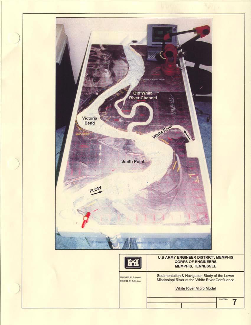
12 MICRO MODEL DESCRIPTION 1. Scales and Bed Materials Plate 7 is a photograph of the hydraulic micro model used in this study. The model insert encompassed the Mississippi River channel between Miles and After entrance and exit conditions in the model were adjusted, the actual study reach was between Miles and The last 2.5 miles of the White River were also included in the model. The scales of the model were 1 inch = 1000 feet, or 1:12000 horizontal, and 1 inch = 100 feet, or 1:1200 vertical, for a 10 to 1 distortion ratio. This distortion supplied the necessary forces required for the simulation of sediment transport conditions similar to the prototype. The bed material was granular plastic urea, Type II, with a specific gravity of Apperturences Discharge hydrographs were simulated by computer via an electronic control system. The system consisted of computer control interfaced with an electronic control valve and submersible pump. A 3-dimensional digitizer was used to monitor water stages and to measure and record the resultant model bed configurations. The model was constructed according to recent aerial photography of the study reach. The riverbanks were constructed out of dense polystyrene, while the realignment section at the confluence was constructed out of oil based clay. Rotational jacks located within the hydraulic flume controlled the slope of the model. 11
13 Surface current patterns were captured using a flow visualization technique developed at AREC. This technique involved using photographic time exposure prints to examine the general surface velocity patterns of the base test and of all design alternative tests. 12
14 MICRO MODEL TESTS 1. Calibration and Verification The calibration/verification of the micro model involved the adjustment of water discharge, sediment volume, hydrograph time scale, and floodplain slope. These parameters were refined until the measured bed response of the model was similar to that of the prototype. A. Design Hydrograph In all model tests, the effective discharge or hydrograph was simulated (1) in the Mississippi River channel only. This hydrograph served as the average design flow response. Because of the constant variation experienced in the prototype, a design hydrograph was used to theoretically analyze the average expected sediment response during any given year. Each hydrograph was run from extreme low flow to near top of bank flow. The time increment or duration of each cycle (peak to peak) was three minutes. Flow was not simulated in the White River. Historic stage and flow records have indicated that the Mississippi River discharge dominates most of the year. The problems this study addresses have been evident mainly when the Mississippi River is at high stage. The White River then, for purposes of this study, was considered a backwater area with no simulation of flow or sediment transport. The bed of the White River above the confluence was molded according to a 1996 hydrographic survey of the study reach (Plate 8). 13
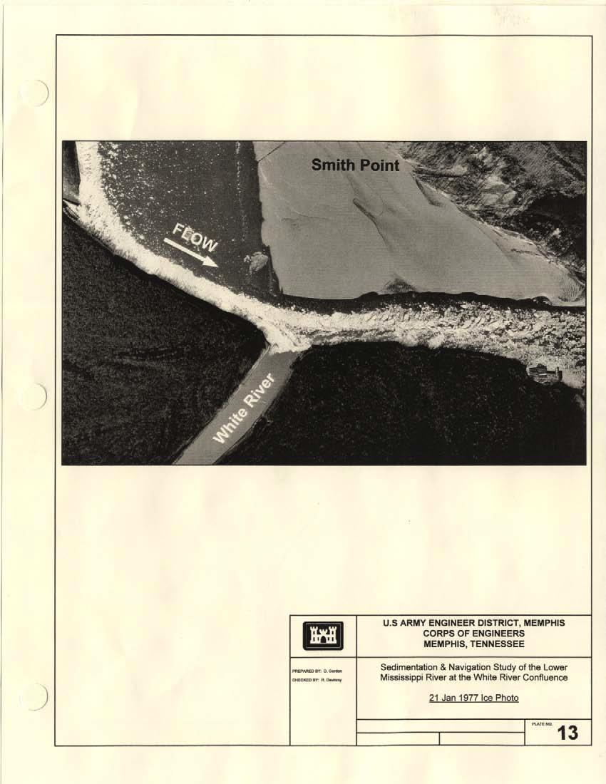
15 B. Prototype Data Several prototype hydrographic surveys were used to determine the general bed characteristics that have existed in the prototype. High water surveys of the Mississippi River from 1994, 1995, 1996, and 1997 are shown on plates 9, 10, 11 and 12, respectively. Older historical surveys were not used for this study because conditions are substantially different today than in the past. All four modern day surveys show almost identical trends. The general trend has been for the formation of a large, high sand bar, above +20 feet LWRP, to occur at Smith Point. Depths in the adjacent main channel have approached 90 feet LWRP. The thalweg has remained on the outside of the bend and against the right descending bankline throughout most of the study reach. A short, deep crossing has developed at the upper end of the study area, while a long, shallow crossing has occurred at the lower end of the study area. A scour hole in excess of 80 feet has been predominant off the right descending bank at the most downstream point of the White River confluence. Plate 13 is a 1977 ice photo of the confluence area. Even though the modern day alignment has changed slightly since this time period, the ice in the photo gave a general representation of flow patterns within the study reach. The ice patterns revealed that the flow in the Mississippi River was concentrated tightly along the right descending bankline well past the White River confluence. Flow deflected slightly off the downstream point of the confluence. Further downstream, the flow began to evenly distribute across the channel before approaching the downstream crossing. Once a favorable comparison of several surveys of both the prototype and model were made, the model was considered calibrated. The resultant survey of this bed response served as both the verification and base test of the micro model (2). 14
16 2. Base Test A. Base Test Survey Plate 14 shows the resultant bed configuration of the micro model base test. The base test was developed from the simulation of successive design hydrographs until bed stability was reached and a similar bed response was achieved as compared with prototype surveys. This survey then served as the comparison survey for all future design alternative tests. Results of the base test and its comparison to the prototype indicated the following trends: At the upper end of the study reach in the model, near Mile 602.5, depths in the thalweg along the left descending bankline approached 90 feet LWRP. The prototype surveys showed depths of less than 60 feet LWRP in this area. A crossing developed in the model near Mile with depths below 20 feet LWRP. The prototype surveys show a slightly deeper crossing in the same area, with depths approaching 50 feet LWRP. These differences were not significant enough to negatively effect the results of this study. The section of the model between Miles 601 and 599 responded exceptionally well as compared to the prototype. The thalweg remained on the right descending bankline in the model through this reach of river. Three major points of curvature inflection occurred in this bend in both the model and the prototype at identical locations. The first point of inflection occurred near Mile 601. Depths in the model approached 90 feet LWRP, while depths in the prototype reached 60 feet LWRP. The second inflection point occurred near Mile 600. Depths in the model approached 80 feet LWRP, while depths in the prototype were near 70 feet LWRP. The last inflection point occurred near Mile 599.5, where depths approached 80 feet LWRP in both the model and in the prototype. On the inside of the bend at Smith Point, between Miles 601 and 598, the formation of a point bar was evident in both the model and prototype. On the 15
17 downstream point of the confluence, near Mile 598.8, a predominant scour hole in excess of 80 feet LWRP developed in both the model and prototype. Both prototype and base test surveys indicated that the channel in the area of the White River confluence was very deep and narrow. At Mile 598, a long, shallow crossing with depths of less than 20 feet LWRP developed in the model. In the prototype, the crossing developed at Mile 597.5, where depths were slightly greater. The crossing ended near Mile in the model, while prototype surveys showed that the crossing ended near Mile Generally, the bathymetric trends established in the micro model were similar to the trends observed in the prototype surveys. The location of the points of inflection within the bend in the model and the prototype were identical. The only minor difference in trends occurred in the downstream crossing, where the crossing in the model began and ended approximately 0.5 miles further upstream than in the prototype. As discussed previously, depths within the White River were molded to between 10 and 20 feet LWRP according to the prototype survey. B. Base Test Flow Visualization In addition to the bathymetry collected from the model, flow visualization information was also recorded. Photographic time exposure was used to examine the general surface velocity patterns of the base test and of each design alternative test. Plate 14 shows the flow visualization photo of the base test. The trends appeared almost identical to those in the 1977 ice photo. The flow patterns in the model showed a point of inflection at Mile 599.5, followed by an impact point on the downstream point of the White River confluence. These points were evident in almost the same location as in the ice photo. The flow was 16
18 concentrated on the right descending bankline throughout the confluence area in both the model and the prototype. Flow patterns then widened downstream of the White River within the crossing. 3. Design Alternative Tests Ten alternative design plans to improve flow and navigation conditions at the confluence of the two rivers were tested in this study. The effectiveness of each plan was evaluated by comparing the resultant bed configuration and flow patterns to that of the base condition. Impacts or changes of each alternative were evaluated by examining both the flow and sediment response of the model. A qualitative evaluation of the ramifications to both upbound and downbound tows was made during team participation meetings at St. Louis, MO. Engineers from the Memphis, St. Louis, Vicksburg, and Little Rock Districts, Mississippi Valley Division, Waterways Experiment Station, and those involved in the navigation industry carefully examined and discussed each alternative. Alternative A: 6 Bendway Weirs at 15 Feet LWRP Placed Upstream of the Confluence Plate 15 is a plan view map of the resultant bed configuration and flow visualization of Alternative A. Test results indicated the thalweg, just upstream of the confluence between Miles 600 and 599, was moved toward the middle of channel. The scour hole at the downstream point of the White River confluence, on the right descending bankline near Mile 599, remained unchanged. The downstream crossing was shorted by 0.8 miles, and the channel deepened approximately 10 feet. The crossing started near Mile but ended near the same location as observed in the base test. Flow visualization photos showed minimal changes in the velocity patterns as compared to the base conditions. 17
19 Alternative B: 9 Bendway Weirs at 15 Feet LWRP (6 Weirs Upstream, as in Alternative A, and 3 Weirs Downstream of the Confluence) Plate 16 is a plan view map of the resultant bed configuration and flow visualization of Alternative B. Between Miles and 598, results indicated that the thalweg decreased in depth and moved toward the middle of the channel. The scour hole on the downstream point of the White River confluence near Mile 599 aggraded approximately 50 feet. The bar across the river at Smith Point between Miles 600 and degraded 10 to 20 feet. The downstream crossing shortened approximately 0.8 miles and deepened by less than 10 feet. The crossing started near Mile but ended near the same location as observed in the base test. Flow visualization showed that the flow patterns were pulled off the right descending bankline. The velocities were completely redistributed across the channel. Alternative C: 7 Bendway Weirs at 15 Feet LWRP (4 Weirs Upstream and 3 Weirs Downstream of the Confluence) Plate 17 is a plan view map of the resultant bed configuration and flow visualization of Alternative C. Between Miles and 598.3, the results indicated the thalweg decreased in depth and moved toward the middle of the channel. The scour hole at the downstream point of the White River confluence aggraded to above 10 feet LWRP. The bar at Smith Point and the downstream crossing both degraded slightly. Flow visualization showed minimal changes in the velocity patterns as compared to the base conditions. Alternative D: 7 Bendway Weirs at 30 Feet LWRP (4 Weirs Upstream and 3 Weirs Downstream of the Confluence) Plate 18 is a plan view map of the resultant bed configuration and flow visualization of Alternative D. Results indicated the thalweg between Miles and remained on the right descending bankline but decreased slightly in depth. The scour hole off the downstream point of the White River confluence aggraded to above 10 feet LWRP. The downstream crossing deepened 10 to 18
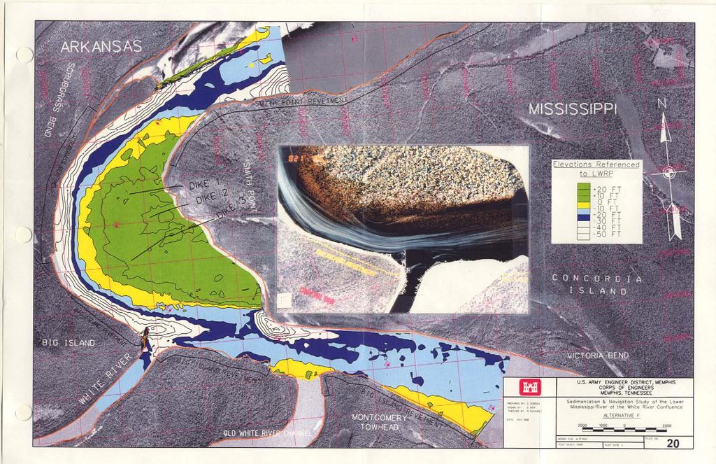
20 20 feet. Flow visualization showed minimal changes in the velocity patterns as compared to the base conditions. Alternative E: 7 Bendway Weirs at 15 Feet LWRP (5 Weirs Upstream and 2 Weirs Downstream of the Confluence) Plate 19 is a plan view map of the resultant bed configuration and flow visualization of Alternative E. Results indicated the thalweg moved towards the middle of the channel between Miles and 598 and the bar at Smith Point degraded. The downstream crossing lengthened slightly and deepened approximately 10 feet. Flow visualization showed that the flow patterns were pulled off the right descending bankline. Velocities were redistributed across the middle of the channel. Alternative F: 700 Foot Dike at +15 Feet LWRP on the Upstream Point of the White River Confluence Plate 20 is a plan view map of the resultant bed configuration and flow visualization of Alternative F. Results indicated a large scour hole approximately 70 feet deep developed off the end of the dike at Mile A short crossing formed between Mile and Mile Near Mile 598.3, the bar at Smith Point laterally eroded back approximately 600 feet as compared to the base condition. Flow visualization showed that the thalweg remained concentrated along the right descending bankline before deflecting off the end of the dike. A boundary shadow of slack water was formed behind the dike and within the mouth of the White River. Alternative G: 800 Foot Longitudinal Dike at +15 Feet LWRP on the Upstream Point of the White River Confluence Plate 21 is a plan view map of the resultant bed configuration and flow visualization of Alternative G. Results indicated that the main channel remained relatively unchanged. The only observed changes were the development of a shallow area off the downstream end of the dike and slight deposition in the 19
21 downstream crossing. Flow visualization showed that the flow patterns remained concentrated on the outside of the bend. An area of slack water developed downstream of the dike and within the mouth of the White River. Alternative H: Major Realignment of the White River Confluence on the Downstream Point Plate 22 is a plan view map of the resultant bed configuration, realignment area and flow visualization of Alternative H. Results indicated that the original 80 foot scour hole at the White River confluence scoured to over 100 feet LWRP. The deepest area of scour occurred within the realigned section. A short, shallow crossing developed between Miles and A 70-foot LWRP scour hole formed off the left descending bankline near Mile Flow visualization showed that the realignment area took the impact from most of the flow in the upstream thalweg. Downstream, the channel crossed over severely to the left descending bank. Alternative I: 7 Bendway Weirs Built 15 Feet LWRP as in Alternative E (5 Weirs Upstream and 2 Weirs Downstream of the Confluence), an 800 Foot Longitudinal Dike Built at +15 Feet LWRP, and a Minor Realignment of the White River Confluence on the Downstream Point Plate 23 is a plan view map of the resultant bed configuration, realignment area, and flow visualization of Alternative I. Results indicated that the thalweg moved toward the middle of the channel between Miles and The scour hole on the downstream point of the White River confluence aggraded, but adequate depth for navigation was maintained. The bar at Smith Point was eroded, while the downstream crossing deepened. Flow visualization showed that the flow patterns moved off the right descending bankline and the velocities were redistributed across the middle of the channel. An area of slack water formed just downstream of the dike and within the confluence. The minor realignment of the confluence did not seem to influence the bed response or the flow conditions. 20
22 Alternative J: 500 Foot Longitudinal Dike Built at +15 Feet LWRP and Minor Realignment of the White River Confluence as in Alternative I Plate 24 is a plan view map of the resultant bed configuration, realignment area, and flow visualization of Alternative J. Results indicated that the thalweg remained relatively unchanged. The scour hole on the downstream point of the White River confluence aggraded. The downstream crossing also remained relatively unchanged. Flow visualization showed that the flow patterns remained concentrated on the outside of the bend before spreading out slightly downstream of the dike. An area of slack water formed just downstream of the dike. The minor realignment of the confluence did not seem to influence the bed response or the flow conditions. 21
23 CONCLUSIONS 1. Summary of Model Tests The following is a summary of the findings and recommendations of the model study: The bendway weirs used in Alternatives A, B, C, D, E, and I were used to redistribute the flow patterns and reduce velocities at the mouth of the White River. The proper alignment and depth of the bendway weirs were the most important aspects of these alternatives. Bendway weirs at 15 feet LWRP, and the alignments shown in Alternatives B, E, and I proved most effective at moving the thalweg and redistributing the velocities across the middle of the channel. Dike structures extending from the mouth of the White River into the Mississippi River navigation channel, such as the one shown in Alternative F, proved effective at improving confluence conditions. However, implementation of these structures would cause an obstruction in the navigation channel of the Mississippi River, which would be a major safety concern. The longitudinal dikes shown in Alternatives G, I, and J proved somewhat effective in improving confluence conditions, but again these plans would pose a major safety concern to tows navigating the Mississippi River. The major realignment of the mouth of the White River shown in Alternative H proved extremely ineffective. This measure resulted in the development of large scour hole off the tip of the realignment section and the development of 22
24 scour against the left descending bankline near Mile A major realignment of the confluence completely altered the downstream flow conditions and sediment response within the Mississippi River. A minor realignment of the confluence, shown in Alternatives I and J, did not display any negative effects to the sediment response, flow patterns, or navigation conditions of the Mississippi River. 2. Recommended Solutions Model tests indicated that the bendway weir configuration in Alternatives E and I proved to be the most effective and economical measure to alleviate the majority of navigation problems at the confluence. The bendway weir configuration in Alternative B proved also to be very effective, but the plan would be more costly to construct. The minor realignment of the confluence in Alternative I did not result in any noticeable changes to the flow patterns observed in Alternative E. Therefore, a minor change in the alignment of the confluence, in combination with bendway weirs, should improve flow conditions. A minor realignment of the mouth of the White River on the downstream point would provide tows with an improved, safer approach to the new lock chamber. A small longitudinal dike extending from the upstream point of the confluence, as in Alternative I, may also be beneficial to further protect tows from high velocities and the strong eddy formation within the confluence. However, any new structure of this type must be constructed small enough so as not to obstruct the flow of traffic in the navigation channel on the Mississippi River. Any minor realignment or construction of a longitudinal dike should be built in conjunction with the bendway weir alignment shown in Alternatives E and I to effectively reduce and redistribute velocities at the confluence. Model tests 23
25 clearly indicated that these measures would improve the flow conditions experienced on the Mississippi River and within the White River confluence. In the interpretation and evaluation of the results of the tests conducted, it should be remembered that the results of these model tests were qualitative in nature. Any hydraulic model, whether physical or numerical, is subject to biases introduced as a result of the inherent complexities that exist in the prototype. Anomalies in actual hydrographic events, such as prolonged periods of high or low flows are not reflected in these results, nor are complex physical phenomena, such as the existence of underlying rock formations or other non-erodable variables. Flood flows were not simulated in this study. 24
26 BIBLIOGRAPHY 1. Leopold, Luna B., A View of the River, Harvard University Press, Cambridge Massachusetts, London, England, Davinroy, Robert D., Physical Sediment Modeling of the Mississippi River on a Micro Scale, University of Missouri-Rolla Thesis, Rolla, Missouri, October Max, Wayne, Records and Notes of the Mouth of White River Assessment, Memphis District Corps of Engineers, Unpublished Report, River Engineering Section,
27 FOR MORE INFORMATION For more information about micro modeling or the Applied River Engineering Center, please contact Robert Davinroy or David Gordon at: Applied River Engineering Center U.S. Army Corps of Engineers - St. Louis District Hydrologic and Hydraulics Branch Foot of Arsenal Street St. Louis, MO Phone: (314) or (314) Fax: (314) Robert.D.Davinroy@mvs02.usace.army.mil David.Gordon@mvs02.usace.army.mil Or you can visit us on the World Wide Web at: 26
28 APPENDIX Plate # s 1 through 24 follow: 1. Vicinity Map and USGS Quad Sheet of the Study Area 2. Nomenclature & Approximate Historical River Alignments 3. Location of the New Montgomery Point Lock & Dam 4. Navigation Problem # 1 5. Navigation Problem # 2 6. Navigation Problem # 3 7. White River Micro Model White River Prototype Survey Prototype Survey Prototype Survey Prototype Survey Prototype Survey Jan 1977 Ice Photo 14. Base Test 15. Alternative A 16. Alternative B 17. Alternative C 18. Alternative D 19. Alternative E 20. Alternative F 21. Alternative G 22. Alternative H 23. Alternative I 24. Alternative J 27

29

30

31
32
33

34
35
36

37
38
39
40
41

42

43

44

45

46

47
48
49
50
51
52
ST. LOUIS SECTION PROJECT OF THE YEAR AWARD
 ST. LOUIS SECTION PROJECT OF THE YEAR AWARD Originality and Innovation The St. Louis Harbor Project is located in the Upper Mississippi River between the entrance to the Chain of Rocks Canal at River
Comparison of Predicted and Measured Shoaling at Morro Bay Harbor Entrance, California
 Comparison of Predicted and Measured Shoaling at Morro Bay Harbor Entrance, California by Edward F. Thompson, Inocencio P. DiRamos, and Robert R. Bottin, Jr. PURPOSE: This Coastal and Hydraulics Engineering
Dredging Keeping Our Underwater Highways Open
 Dredging Keeping Our Underwater Highways Open Sedimentation Material that falls to the bottom of a liquid is called sediment. If enough sediment deposits to build a shallow spot on the river or ocean bottom,
Inlet Management Study for Pass-A-Grille and Bunces Pass, Pinellas County, Florida
 Inlet Management Study for Pass-A-Grille and Bunces Pass, Pinellas County, Florida Final Report Submitted By Ping Wang, Ph.D., Jun Cheng Ph.D., Zachary Westfall, and Mathieu Vallee Coastal Research Laboratory
APPENDIX J HYDROLOGY AND WATER QUALITY
 APPENDIX J HYDROLOGY AND WATER QUALITY J-1 Technical Report on Airport Drainage, Northern Sector Airport and Ordinance Creek Watershed / Preliminary Creek Constructed Natural Channel Culvert J-2 Preliminary
Annex E Bridge Pier Protection Plan
 Annex E Bridge Pier Protection Plan Table E1 Bridge Types and Locations Table E2 Flow Conditions For River Sections Figure E1 Bridge Abutment Protection Figure E2 Bridge Pier Protection Figure E3 Central
Plan B Dam Breach Assessment
 Plan B Dam Breach Assessment Introduction In support of the Local Sponsor permit applications to the states of Minnesota and North Dakota, a dam breach analysis for the Plan B alignment of the Fargo-Moorhead
Illinois State Water Survey
 Illinois State Water Survey HYDROLOGY DIVISION SWS Contract Report 508 COMPARISON OF 1987 AND 1989 BED PROFILE SURVEYS OF THE LOWER CACHE RIVER by Richard Allgire Office of Sediment and Wetland Studies
Minnesota Department of Natural Resources Division of Fish and Wildlife Section of Fisheries. Stream Survey Report. Luxemburg Creek.
 Minnesota F-29-R(P)-24 Area 315 Study 3 March 2016 Minnesota Department of Natural Resources Division of Fish and Wildlife Section of Fisheries Stream Survey Report Luxemburg Creek 2015 Mark Pelham Sauk
AIS data analysis for vessel behavior during strong currents and during encounters in the Botlek area in the Port of Rotterdam
 International Workshop on Next Generation Nautical Traffic Models 2013, Delft, The Netherlands AIS data analysis for vessel behavior during strong currents and during encounters in the Botlek area in the
NUMERICAL AND PHYSICAL MODELING
 POINTE DU BOIS GENERATING STATION SPILLWAY REPLACEMENT PROJECT NUMERICAL AND PHYSICAL MODELING Kara Hurtig, Northwest Hydraulic Consultants, North Vancouver, BC, Canada David S. Brown, KGS Group, Winnipeg,
Request Number IR1-12: Flow Passage. Information Request
 Request Number IR1-12: Flow Passage Information Request Provide additional information about the 100 metre flow passage channel scenario between the Westshore Terminals and the proposed Project terminal
Summary of HEC 18, Evaluating Scour at Bridges FHWA NHI Should really follow HEC 18, but this summary will get you the main points.
 Summary of HEC 18, Evaluating Scour at Bridges FHWA NHI 01-001 Should really follow HEC 18, but this summary will get you the main points. 1: Determine scour analysis variables 2: Analyze long-term bed
COUPLED MANAGEMENT STRATEGY LAKE CATHIE ESTUARY & COAST
 Lake Cathie Progress Association Inc. ABN 28 251 433 854 P.O. Box 247 Lake Cathie NSW 2445 PHONE/FAX: 02 6584 8211 EMAIL: r3packag@bigpond.com 20 th October 2009 Port Macquarie Hastings Council PO Box
Figure 4, Photo mosaic taken on February 14 about an hour before sunset near low tide.
 The Impact on Great South Bay of the Breach at Old Inlet Charles N. Flagg and Roger Flood School of Marine and Atmospheric Sciences, Stony Brook University Since the last report was issued on January 31
Environmental. Effects of Dredging
 Envi~onmental Effects of Dredging Technical Notes THE VALUE OF GRAVEL DISPOSAL MOUNDS IN RIVER SIDE CHANNELS FOR FRESHWATER MUSSELS PURPOSE: This note provides information on the value of gravel disposal
DRAFT. October 17, 2014 File No Mr. Brendhan Zubricki Town Administrator Essex Town Hall 30 Martin Street Essex, MA.
 GZA GeoEnvironmental, Inc. Engineers and Scientists October 17, 2014 File No. 18.0171857.00 Mr. Brendhan Zubricki Town Administrator Essex Town Hall 30 Martin Street Essex, MA. 01929 DRAFT Re: Essex River
Greenup Lock Filling and Emptying System Study
 Fourth LACCEI International Latin American and Caribbean Conference for Engineering and Technology (LACCET 2006) Breaking Frontiers and Barriers in Engineering: Education, Research and Practice 21-23 June
Enclosure (5) to NVIC 03-16
 to NVIC 03-16") TOWING OFFICER ASSESSMENT RECORD LIMITED LOCAL AREA LOCAL LIMITED AREA (LLA) TOAR INSTRUCTIONS FOR USE The following Towing Officer Assessment Record (TOAR) is intended as a model for endorsements as Limited
TOWING OFFICER ASSESSMENT RECORD LIMITED LOCAL AREA LOCAL LIMITED AREA (LLA) TOAR INSTRUCTIONS FOR USE The following Towing Officer Assessment Record (TOAR) is intended as a model for endorsements as Limited
CORPS FACTS. Harbor Dredging U.S. ARMY CORPS OF ENGINEERS BUILDING STRONG
 CORPS FACTS Harbor Dredging U.S. ARMY CORPS OF ENGINEERS BUILDING STRONG Disaster Response Sedimentation in the channel is caused by the normal cycle of silt movement, erosion from high water or heavy
OFFICE OF STRUCTURES MANUAL FOR HYDROLOGIC AND HYDRAULIC DESIGN CHAPTER 11 APPENDIX B TIDEROUT 2 USERS MANUAL
 OFFICE OF STRUCTURES MANUAL FOR HYDROLOGIC AND HYDRAULIC DESIGN CHAPTER 11 APPENDIX B TIDEROUT 2 USERS MANUAL APRIL 2011 APRIL 2011 Page 1 Preface TIDEROUT 2, Build 1.22 dated June 29, 2006 is the current
Lower Mekong Basin. John G. Williams. Petrolia, California.
 Technical Comment on Sabo et al. Designing river flows to improve food security futures in the Lower Mekong Basin John G. Williams Petrolia, California jgwill@frontiernet.net Abstract: Sabo et al. (1)
FOR INFORMATION ONLY. Gold Coast Seaway Channel Scour and Rock Wall Stability Investigation. R.B doc December 2011
 A part of BMT in Energy and Environment Gold Coast Seaway Channel Scour and Rock Wall Stability Investigation R.B18625.001.00.doc December 2011 Gold Coast Seaway Channel Scour and Rock Wall Stability Investigation
Ermenek Dam and HEPP: Spillway Test & 3D Numeric-Hydraulic Analysis of Jet Collision
 Ermenek Dam and HEPP: Spillway Test & 3D Numeric-Hydraulic Analysis of Jet Collision J.Linortner & R.Faber Pöyry Energy GmbH, Turkey-Austria E.Üzücek & T.Dinçergök General Directorate of State Hydraulic
SECTION 2 HYDROLOGY AND FLOW REGIMES
 SECTION 2 HYDROLOGY AND FLOW REGIMES In this section historical streamflow data from permanent USGS gaging stations will be presented and discussed to document long-term flow regime trends within the Cache-Bayou
Lecture 1 Why Do We Have Levees in Louisiana? J. David Rogers, Ph.D., P.E., R.G.
 Lecture 1 Why Do We Have Levees in Louisiana? J. David Rogers, Ph.D., P.E., R.G. Karl F. Hasselmann Chair in Geological Engineering Missouri University of Science & Technology for the First Annual Levee
HYDRAULIC JUMP AND WEIR FLOW
 HYDRAULIC JUMP AND WEIR FLOW 1 Condition for formation of hydraulic jump When depth of flow is forced to change from a supercritical depth to a subcritical depth Or Froude number decreases from greater
Advanced Hydraulics Prof. Dr. Suresh A. Kartha Department of Civil Engineering Indian Institute of Technology, Guwahati
 Advanced Hydraulics Prof. Dr. Suresh A. Kartha Department of Civil Engineering Indian Institute of Technology, Guwahati Module - 4 Hydraulic Jumps Lecture - 1 Rapidly Varied Flow- Introduction Welcome
USING A LABYRINTH WEIR TO INCREASE HYDRAULIC CAPACITY. Dustin Mortensen, P.E. 1 Jake Eckersley, P.E. 1
 USING A LABYRINTH WEIR TO INCREASE HYDRAULIC CAPACITY Dustin Mortensen, P.E. 1 Jake Eckersley, P.E. 1 Plum Creek Floodwater Retarding Structure No. 6 is located in an area of Kyle, Texas, that is currently
Final Bull Trout Redd Monitoring Report for the Wallowa Falls Hydroelectric Project
 Final for the Wallowa Falls Hydroelectric Project East Fork Wallowa River barrier to upstream fish migration, photo courtesy of Kendrick Moholt (FERC No. P-308) December 18, 2017 Prepared by: Jeremiah
Experimental Investigation on Changes of Water Surface Profile with Gaussian Shaped Bottom and Side Roughness
 Experimental Investigation on Changes of Water Surface Profile with Gaussian Shaped Bottom and Side Md. Rafiue Islam a, Shariful Islam b*, Md. Abdul Qaiyum Talukder c, S. M. Rezwan Hossain d Abstract Bed
Long Beach Island Holgate Spit Little Egg Inlet Historical Evolution Introduction Longshore Transport Map, Survey and Photo Historic Sequence
 Appendix B Long Beach Island Holgate Spit Little Egg Inlet Historical Evolution Introduction The undeveloped southern end of Long Beach Island (LBI) is referred to as the Holgate spit as it adjoins the
Aquatic Organism Passage at Road-Stream Crossings CHUCK KEEPORTS FOREST HYDROLOGIST ALLEGHENY NATIONAL FOREST WARREN, PENNSYLVANIA
 Aquatic Organism Passage at Road-Stream Crossings CHUCK KEEPORTS FOREST HYDROLOGIST ALLEGHENY NATIONAL FOREST WARREN, PENNSYLVANIA TOPICS COVERED Aquatic Organism Passage (AOP) Benefits of AOP Crossings
Culvert Design for Low and High Gradient Streams in the Midwest. Dale Higgins, Hydrologist Chequamegon-Nicolet National Forest
 Culvert Design for Low and High Gradient Streams in the Midwest Dale Higgins, Hydrologist Chequamegon-Nicolet National Forest Overview Culvert Design Considerations Hydraulic Terms Culvert Impacts Low
Creek Trash Assessment (CTA) Methodology (Demonstration: Mill Run Creek, Cheltenham, Pa.)
 Methodology (Demonstration: Mill Run Creek, Cheltenham, Pa.)") Creek Trash Assessment (CTA) Methodology (Demonstration: Mill Run Creek, Cheltenham, Pa.) Mill Run Creek emerges from a storm sewer in Philadelphia to an open creek in Cheltenham. The Creek downstream
Creek Trash Assessment (CTA) Methodology (Demonstration: Mill Run Creek, Cheltenham, Pa.) Mill Run Creek emerges from a storm sewer in Philadelphia to an open creek in Cheltenham. The Creek downstream
Impact of Dredging the Lower Narrow River on Circulation and Flushing
 Impact of Dredging the Lower Narrow River on Circulation and Flushing Craig Swanson Ph.D. Swanson Environmental Alex Shaw Ocean Engineering, URI Prof. Malcolm L. Spaulding Ocean Engineering, URI 29 January
STUDY ON TSUNAMI PROPAGATION INTO RIVERS
 ABSTRACT STUDY ON TSUNAMI PROPAGATION INTO RIVERS Min Roh 1, Xuan Tinh Nguyen 2, Hitoshi Tanaka 3 When tsunami wave propagation from the narrow river mouth, water surface is raised and fluctuated by long
Modelling of Pressurised Pipes within InfoWorks ICM and CS
 Modelling of Pressurised Pipes within InfoWorks ICM and CS 1. Introduction Correctly modelling pressurised pipes, variously described as forcemains or rising mains, can be one of the more difficult aspects
North Diversion Channel Physical Modeling:
 North Diversion Channel Physical Modeling: Bike Notch Implementation Between Vineyard Arroyo Confluence to Osuna Bridge August 29, 2011 Prepared for Albuquerque Metropolitan Arroyo Flood Control Authority
Towed Barge Standard of Care
 Lower Columbia Region Harbor Safety Committee Towed Barge Standard of Care Page 1 of 6 A. 1. Purpose The Columbia River is intended to eliminate conflicts between towing vessels conducting astern towing
APPENDIX C VEGETATED EMERGENCY SPILLWAY. VERSION 1.0 March 1, 2011
 APPENDIX C VEGETATED EMERGENCY SPILLWAY VERSION 1.0 March 1, 2011 [NOTE: Could use a better photo more clearly showing the emergency spillway in the context of the dam.] SECTION C-1: DESCRIPTION OF PRACTICE
Appendix E Cat Island Borrow Area Analysis
 Appendix E Cat Island Borrow Area Analysis ERDC/CHL Letter Report 1 Cat Island Borrow Area Analysis Multiple borrow area configurations were considered for Cat Island restoration. Borrow area CI1 is located
Hydrologic, Hydraulic and Geomorphic Technical Memorandum
 Appendix A Hydrologic, Hydraulic and Geomorphic Technical Memorandum 01054/8410233/14/Rohner_Alt_Analysis_Report Rohner Creek Flood Control, Habitat and Seismic Improvement Project Alternatives Analysis
HURRICANE SANDY LIMITED REEVALUATION REPORT UNION BEACH, NEW JERSEY DRAFT ENGINEERING APPENDIX SUB APPENDIX D SBEACH MODELING
 HURRICANE SANDY LIMITED REEVALUATION REPORT UNION BEACH, NEW JERSEY DRAFT ENGINEERING APPENDIX SUB APPENDIX D SBEACH MODELING Rev. 18 Feb 2015 1 SBEACH Modeling 1.0 Introduction Following the methodology
Khosla's theory. After studying a lot of dam failure constructed based on Bligh s theory, Khosla came out with the following;
 Khosla's theory After studying a lot of dam failure constructed based on Bligh s theory, Khosla came out with the following; Following are some of the main points from Khosla's Theory From observation
CROSS-SHORE SEDIMENT PROCESSES
 The University of the West Indies Organization of American States PROFESSIONAL DEVELOPMENT PROGRAMME: COASTAL INFRASTRUCTURE DESIGN, CONSTRUCTION AND MAINTENANCE A COURSE IN COASTAL DEFENSE SYSTEMS I CHAPTER
3. GRADUALLY-VARIED FLOW (GVF) AUTUMN 2018
 AUTUMN 2018") 3. GRADUALLY-VARIED FLOW (GVF) AUTUMN 2018 3.1 Normal Flow vs Gradually-Varied Flow V 2 /2g EGL (energy grade line) Friction slope S f h Geometric slope S 0 In flow the downslope component of weight balances
3. GRADUALLY-VARIED FLOW (GVF) AUTUMN 2018 3.1 Normal Flow vs Gradually-Varied Flow V 2 /2g EGL (energy grade line) Friction slope S f h Geometric slope S 0 In flow the downslope component of weight balances
The Continuing Evolution of the New Inlet
 The Continuing Evolution of the New Inlet Charles N. Flagg, Roger Flood and Robert Wilson School of Marine and Atmospheric Sciences, Stony Brook University It is now a year plus since super storm Sandy
CHAPTER 134 INTRODUCTION
 CHAPTER 134 NEW JETTIES FOR TUNG-KANG FISHING HARBOR, TAIWAN Chi-Fu Su Manager Engineering Department Taiwan Fisheries Consultants, Inc. Taipei, Taiwan INTRODUCTION Tung-Kang Fishing Harbor, which is about
Boston s Pilot Project to Measure CSO Flows Relies on New Technology and Scattergraphs to Detect Overflows
 Boston s Pilot Project to Measure CSO Flows Relies on New Technology and Scattergraphs to Detect Overflows Paul Keohan, P.E.*, Michael Armes, PMP 1, Patrick Stevens, P.E. 2 Boston Water and Sewer Commission
Julebæk Strand. Effect full beach nourishment
 Julebæk Strand Effect full beach nourishment Aim of Study This study is a part of the COADAPT funding and the aim of the study is to analyze the effect of beach nourishment. In order to investigate the
Volume and Shoreline Changes along Pinellas County Beaches during Tropical Storm Debby
 Volume and Shoreline Changes along Pinellas County Beaches during Tropical Storm Debby Ping Wang and Tiffany M. Roberts Coastal Research Laboratory University of South Florida July 24, 2012 Introduction
DUXBURY WAVE MODELING STUDY
 DUXBURY WAVE MODELING STUDY 2008 Status Report Duncan M. FitzGerald Peter S. Rosen Boston University Northeaster University Boston, MA 02215 Boston, MA 02115 Submitted to: DUXBURY BEACH RESERVATION November
Hydrographic Surveying Methods, Applications and Uses
 Definition: Hydrographic Surveying Methods, Applications and Uses It is the branch of surveying which deals with any body of still or running water such as a lake, harbor, stream or river. Hydrographic
from ocean to cloud HEAVY DUTY PLOUGH PERFORMANCE IN VERY SOFT COHESIVE SEDIMENTS
 HEAVY DUTY PLOUGH PERFORMANCE IN VERY SOFT COHESIVE SEDIMENTS Geoff Holland, Sarah Dzinbal (Alcatel-Lucent Submarine Networks) Email: geoff.holland@alcatel-lucent.com Alcatel-Lucent Submarine Networks
TROUT CREEK WATERSHED (Second Year of Snowline Data)
") Extent of Snow Cover During the 2002 Spring Freshet For the TROUT CREEK WATERSHED (Second Year of Snowline Data) (Penticton Forest District) 1.0 INTRODUCTION The extent of snow cover over a watershed basin
Extent of Snow Cover During the 2002 Spring Freshet For the TROUT CREEK WATERSHED (Second Year of Snowline Data) (Penticton Forest District) 1.0 INTRODUCTION The extent of snow cover over a watershed basin
Hydraulic Modeling of Stream Enhancement Methods
 Hydraulic Modeling of Stream Enhancement Methods Matthew J. Curry John J. Levitsky Abstract Development within watersheds increases the amounts of runoff causing stream erosion and degradation of stream
STRUCTURE S-65 PURPOSE SPILLWAY OPERATION
 STRUCTURE S-65 This structure is a reinforced concrete, gated spillway with discharge controlled by three cable operated, vertical lift gates, and a reinforced concrete lock structure with two pairs of
WASHINGTON CONSERVATION DISTRICT STANDARD OPERATING PROCEDURE (S.O.P.)
") Page 1 of 18 Water Monitoring Program WASHINGTON CONSERVATION DISTRICT STANDARD OPERATING PROCEDURE (S.O.P.) No. 1 FLOW MONITORING Page 2 of 18 Water Monitoring Program Standard Operating Procedure No.
Page 1 of 18 Water Monitoring Program WASHINGTON CONSERVATION DISTRICT STANDARD OPERATING PROCEDURE (S.O.P.) No. 1 FLOW MONITORING Page 2 of 18 Water Monitoring Program Standard Operating Procedure No.
TOP:001.3 U.S. Fish and Wildlife Service TECHNICAL OPERATING PROCEDURE
 TOP:001.3 March 12, 2015 U.S. Fish and Wildlife Service Marquette Biological Station 3090 Wright Street Marquette, Michigan 49855 U.S.A. and U.S. Fish and Wildlife Service Ludington Biological Station
EFFECTS ON CUTTER SUCTION DREDGE PRODUCTION WHILE DREDGING SIMULATED DEBRIS IN THE LABORATORY
 EFFECTS ON CUTTER SUCTION DREDGE PRODUCTION WHILE DREDGING SIMULATED DEBRIS IN THE LABORATORY R. Randall 1, M. Warwick 2, J. Henriksen 3, D. Young 4, and A. Manikantan 5 ABSTRACT The cutter suction dredge
FLUID FORCE ACTING ON A CYLINDRICAL PIER STANDING IN A SCOUR
 BBAA VI International Colloquium on: Bluff Bodies Aerodynamics & Applications Milano, Italy, July, 20-24 2008 FLUID FORCE ACTING ON A CYLINDRICAL PIER STANDING IN A SCOUR Takayuki Tsutsui Department of
Performance of Upham Beach T-Groin Project and Its Impact to the Downdrift Beach
 Performance of Upham Beach T-Groin Project and Its Impact to the Downdrift Beach Progress Report for the Period of October 2008 to April 2009 Submitted by Ping Wang, Ph.D., and Tiffany M. Roberts Department
Investigation of Suction Process of Scroll Compressors
 Purdue University Purdue e-pubs International Compressor Engineering Conference School of Mechanical Engineering 2006 Investigation of Suction Process of Scroll Compressors Michael M. Cui Trane Jack Sauls
SPILLWAY REPLACEMENT PROJECT NUMERICAL AND PHYSICAL MODELING. Kara Hurtig, Water Resources Engineer, Northwest Hydraulic Consultants, BC, Canada
 POINTE DU BOIS GENERATING STATION SPILLWAY REPLACEMENT PROJECT NUMERICAL AND PHYSICAL MODELING Kara Hurtig, Water Resources Engineer, Northwest Hydraulic Consultants, BC, Canada David S. Brown, Senior
NUMERICAL INVESTIGATION OF THE FLOW BEHAVIOUR IN A MODERN TRAFFIC TUNNEL IN CASE OF FIRE INCIDENT
 - 277 - NUMERICAL INVESTIGATION OF THE FLOW BEHAVIOUR IN A MODERN TRAFFIC TUNNEL IN CASE OF FIRE INCIDENT Iseler J., Heiser W. EAS GmbH, Karlsruhe, Germany ABSTRACT A numerical study of the flow behaviour
Experimental Investigation of Clear-Water Local Scour at Pile Groups
 Experimental Investigation of Clear-Water Local Scour at Pile Groups B. Ataie-Ashtiani 1 and A. A. Beheshti 2 Abstract: Experiments of local scour around pile groups are carried out under steady clear-water
Paper Environmental friendly solutions to improve the navigation fairway of the Danube in Serbia
 Paper 166 - Environmental friendly solutions to improve the navigation fairway of the Danube in Serbia ZUIJDERWIJK Michel, MUSKATIROVIC Jasna, MITROVIC Ivan, TJERRY Soren, ZANETTI Roberto Witteveen+Bos,
EPA R6 Dive Team Operations Report. San Jacinto Waste Pits Channelview, TX December 9-10, 2015
 EPA R6 Dive Team Operations Report San Jacinto Waste Pits Channelview, TX December 9-10, 2015 BACKGROUND The San Jacinto River Waste Pit Site history has been documented in several documents prepared for,
Trout Unlimited Comments on the Scope of Environmental Impact Statement for the Constitution Pipeline Project, Docket No. PF12-9
 October 9, 2012 Kimberly D. Bose, Secretary Federal Energy Regulatory Commission 888 First Street, NE, Room 1A Washington, DC 20426 RE: Trout Unlimited Comments on the Scope of Environmental Impact Statement
Nearshore Placed Mound Physical Model Experiment
 Nearshore Placed Mound Physical Model Experiment PURPOSE: This technical note describes the migration and dispersion of a nearshore mound subjected to waves in a physical model. The summary includes recommendations
ANSWERS TO QUESTIONS IN THE NOTES AUTUMN 2018
 ANSWERS TO QUESTIONS IN THE NOTES AUTUMN 2018 Section 1.2 Example. The discharge in a channel with bottom width 3 m is 12 m 3 s 1. If Manning s n is 0.013 m -1/3 s and the streamwise slope is 1 in 200,
A methodology for evaluating the controllability of a ship navigating in a restricted channel
 A methodology for evaluating the controllability of a ship navigating in a restricted channel K. ELOOT A, J. VERWILLIGEN B AND M. VANTORRE B a Flanders Hydraulics Research (FHR), Flemish Government, Antwerp,
River Dynamics - Rafting FOCUS. Read 10 point text from rear of the room. Bottom
 Dynamics - Rafting FOCUS Read 10 point text from rear of the room. Bottom 1 This section focuses on rivers; how they flow and on some basic maneuvers which you can execute on the river. Dynamics Rafting:
The Impact on Great South Bay of the Breach at Old Inlet Charles N. Flagg School of Marine and Atmospheric Sciences, Stony Brook University
 The Impact on Great South Bay of the Breach at Old Inlet Charles N. Flagg School of Marine and Atmospheric Sciences, Stony Brook University The previous report provided a detailed look at the conditions
1. An aid to navigation is any object external to the boat that: 1) helps a boater pilot a boat safely, 2) aids a boater in finding position and 3)
 helps a boater pilot a boat safely, 2) aids a boater in finding position and 3)") 1. An aid to navigation is any object external to the boat that: 1) helps a boater pilot a boat safely, 2) aids a boater in finding position and 3) a. marks the best fishing holes. b. provides a place
1. An aid to navigation is any object external to the boat that: 1) helps a boater pilot a boat safely, 2) aids a boater in finding position and 3) a. marks the best fishing holes. b. provides a place
IMPACTS OF COASTAL PROTECTION STRATEGIES ON THE COASTS OF CRETE: NUMERICAL EXPERIMENTS
 IMPACTS OF COASTAL PROTECTION STRATEGIES ON THE COASTS OF CRETE: NUMERICAL EXPERIMENTS Tsanis, I.K., Saied, U.M., Valavanis V. Department of Environmental Engineering, Technical University of Crete, Chania,
Table 4. Volumetric Change Rates Pre-Project and Post-Project for the Town of Duck
 V. VOLUMETRIC CHANGES General Volumetric changes measured over the entire monitoring area for various time periods are provided in Table 4. The volume changes are given in terms of cubic yards/foot of
2012 Susitna River Water Temperature and Meteorological Field Study
 (FERC No. 14241) 2012 Susitna River Water Temperature and Meteorological Field Study Appendix A Prepared for Prepared by URS Corporation Tetra Tech Inc. February 2013 APPENDIX A: PHOTOGRAPHS AND SITE INFORMATION
BILLY BISHOP TORONTO CITY AIRPORT PRELIMINARY RUNWAY DESIGN COASTAL ENGINEERING STUDY
 Bâtiment Infrastructures municipales Transport Industriel Énergie Environnement BILLY BISHOP TORONTO CITY AIRPORT PRELIMINARY RUNWAY DESIGN COASTAL ENGINEERING STUDY N. Guillemette 1, C. Glodowski 1, P.
CLAM PASS ANNUAL RESTORATION & MANAGEMENT PLAN TIDAL ANALYSIS ELEMENT REPORT NO. 13
 CLAM PASS ANNUAL RESTORATION & MANAGEMENT PLAN TIDAL ANALYSIS ELEMENT REPORT NO. 13 Submitted to: Pelican Bay Services Division Prepared by: Humiston & Moore Engineers H&M File No. 13-078 November 2012
Quantifying Performance of Stream Simulation Culverts in the Chehalis Basin, WA
 Quantifying Performance of Stream Simulation Culverts in the Chehalis Basin, WA AUTHORS: Joe Richards, Environmental Science Associates Jane Atha, Washington Department of Fish & Wildlife Colin Thorne,
APPENDIX C ESTIMATING SCOUR IN BOTTOMLESS ARCH CULVERTS
 OFFICE OF STRUCTURES MANUAL FOR HYDROLOGIC AND HYDRAULIC DESIGN CHAPTER 11, EVALUATING SCOUR AT BRIDGES APPENDIX C ESTIMATING SCOUR IN BOTTOMLESS ARCH CULVERTS APRIL 2011 APPENDIX C ESTIMATING SCOUR IN
MONITORING SEDIMENT TRANSPORT PROCESSES AT MANAVGAT RIVER MOUTH, ANTALYA TURKEY
 COPEDEC VI, 2003 in Colombo, Sri Lanka MONITORING SEDIMENT TRANSPORT PROCESSES AT MANAVGAT RIVER MOUTH, ANTALYA TURKEY Isikhan GULER 1, Aysen ERGIN 2, Ahmet Cevdet YALCINER 3 ABSTRACT Manavgat River, where
MODELLING ANCILLARIES: WEIR COEFFICIENTS
 WaPUG USER NOTE No 27 MODELLING ANCILLARIES: WEIR COEFFICIENTS David Balmforth, MWH 1. SCOPE This user note gives advice on the choice of coefficient for overflo eirs and orifices hen modelling storm seage
Application of Computational Fluid Dynamics to Compressor Efficiency Improvement
 Purdue University Purdue e-pubs International Compressor Engineering Conference School of Mechanical Engineering 1994 Application of Computational Fluid Dynamics to Compressor Efficiency Improvement J.
APPENDIX C. Fluvial and Tidal Hydraulics Report
 APPENDIX C Fluvial and Tidal Hydraulics Report BUENA VISTA LAGOON ENHANCEMENT PROJECT FLUVIAL AND TIDAL HYDRAULICS ANALYSES Prepared for: SANDAG 401 B Street, Suite 800 San Diego, California 92101 Contact:
TABLE ROCK LAKE 2014 ANNUAL LAKE REPORT. Shane Bush Fisheries Management Biologist Missouri Department of Conservation Southwest Region
 TABLE ROCK LAKE 14 ANNUAL LAKE REPORT Shane Bush Fisheries Management Biologist Missouri Department of Conservation Southwest Region March 1, 15 EXECUTIVE SUMMARY Table Rock Lake is a 43,1 acre reservoir
Designing Labyrinth Spillways for Less than Ideal Conditions Real World Application of Laboratory Design Methods
 Designing Labyrinth Spillways for Less than Ideal Conditions Real World Application of Laboratory Design Methods Gregory Richards, P.E., CFM, Gannett Fleming, Inc. Blake Tullis, Ph.D., Utah Water Research
INCREASE METHODS OF DRAINAGE DISCHARGE OF INUNDATED WATER IN LOW FLAT LAND CONSIDERING BED DEFORMATION CHARACTERISTICS
 INCREASE METHODS OF DRAINAGE DISCHARGE OF INUNDATED WATER IN LOW FLAT LAND CONSIDERING BED DEFORMATION CHARACTERISTICS Hiroshi Takebayashi 1, Sornthep Vannarat 2 and Saifhon Tomkratoke 2 1. Disaster Prevention
Effect of Fluid Density and Temperature on Discharge Coefficient of Ogee Spillways Using Physical Models
 RESEARCH ARTICLE Effect of Fluid Density and Temperature on Discharge Coefficient of Ogee Spillways Using Physical Models M. SREENIVASULU REDDY 1 DR Y. RAMALINGA REDDY 2 Assistant Professor, School of
Cline s Point Marina Ship Wave Analysis
 Cline s Point Marina Ship Wave Analysis Draft Technical Report April 13, 2015 Submitted To: Port of Corpus Christi Authority Prepared for: Port of Corpus Christi Authority This document is intended for
NEED FOR SUPPLEMENTAL BATHYMETRIC SURVEY DATA COLLECTION
 305 West Grand Avenue, Suite 300 Montvale, New Jersey 07645 Phone 201.930.9890 Fax 201.930.9805 www.anchorqea.com M EMORANDUM To: Caroline Kwan and Nica Klaber U.S. Environmental Protection Agency Region
EQUIPMENT AND PERSONNEL
 1 EQUIPMENT AND PERSONNEL Inland Rivers and Gulf Coast 2013 Section 4 Topics 4.1 Equipment Boats 4.1.1 Types and Sizes of Towboats 4.1.2 Main Propulsion Equipment 4.2 Equipment Barges 4.2.1 Barge Sizes,
Technical Report Culvert A Hydraulic Analysis
 DATE: November 3, 2011 Technical Report Culvert A Hydraulic Analysis TO: FROM: RE: Jim Reiser, P.E. Project Manager Parsons Brinckerhoff, Inc. Kurt Killian, P.E., CFM Parsons Brinckerhoff, Inc. Design
Inlet Swirl on Turbocharger Compressor Performance
 Inlet Swirl on Turbocharger Compressor Performance Lei Huang, Ying Liu, Hua Chen* National laboratory of Engine Turbocharging Technology, Tianjin, China *corresponding author: Tel.:+86-22-5870-7069; fax:
Assessment of Baseline Geomorphic Features at. Proposed Stream Crossings On The Proposed County Road 595. Marquette County, Michigan
 Assessment of Baseline Geomorphic Features at Proposed Stream Crossings On The Proposed County Road 595 Marquette County, Michigan Prepared for: Kennecott Eagle Minerals Company Marquette, Michigan Prepared
FISH PASSAGE ALTERNATIVES ANALYSIS ON PENNYPACK CREEK AT VERREE ROAD DAM AND ROOSEVELT BOULEVARD DAM PHILADELPHIA, PENNSYLVANIA
 FISH PASSAGE ALTERNATIVES ANALYSIS ON PENNYPACK CREEK AT VERREE ROAD DAM AND ROOSEVELT BOULEVARD DAM PHILADELPHIA, PENNSYLVANIA Prepared for: One Parkway, 10 th Floor 1515 Arch Street Philadelphia, PA
DEAD-ENDCHANNELFLUSHINGINHARBORS
 DEAD-ENDCHANNELFLUSHNGNHARBORS PURPOSE: The purpose of this technical note is to present some design con- siderations which benefit dead-end channel flushing. Some of these factors can also be used to
The Challenge of Wave Scouring Design for the Confederation Bridge
 13: Coastal and Ocean Engineering ENGI.8751 Undergraduate Student Forum Faculty of Engineering and Applied Science, Memorial University, St. John s, NL, Canada MARCH 2013 Paper Code. (13 - walsh) The Challenge