DRAFT BETTER STREETS PLAN PLAN REVISIONS 2) ATTACHMENTS
|
|
|
- Martin Webster
- 5 years ago
- Views:
Transcription


")
1 DRAFT BETTER STREETS PLAN PLAN REVISIONS 2) ATTACHMENTS OCTOBER 2009
2 Attachment A 10/14/2009 * This section would be added as a sidebar in Chapter 2 (Section 2.3, page 28) of the Draft Better Streets Plan. Follow the link to see the original chapter. New Sidebar Streetscape Maintenance: Rights and Responsibilities Maintenance of public streets and sidewalks in San Francisco is split among various public agencies, utilities, and property owners. Roadways The roadway is generally maintained by DPW, including travel lanes and parking lanes. Catch basins are managed by the PUC, but maintained by DPW. Utility providers often excavate in the roadway to maintain or repair utility lines utility providers are required to replace paving in kind per the Public Works Code (Article 2.4) and DPW Director s Order #176,707 (Section 12.4.B). Sidewalks On most streets in San Francisco, sidewalk maintenance and repair is the responsibility of the fronting property owner. Resources are available through DPW s Sidewalk Inspection and Repair Program (SIRP), which enables property owners to use DPW contractors to repair sidewalks. The Sidewalk Landscape Permit is also available through DPW, which enables property owners to replace portions of the sidewalk in front of their property with landscaping, which may preclude the need to repair portions of broken sidewalk. SIRP: Sidewalk landscape permit: Utility providers often excavate in the sidewalk to maintain or repair utility lines utility providers are required to replace paving in kind per the Public Works Code (Article 2.4) and DPW Director s Order #176,707 (Section 12.4.B). Utilities Utility main lines are the maintenance responsibility of the utility provider. However, utility laterals (which connect from individual parcels to the main line) are typically the responsibility of the property owner to maintain or repair. Street trees and landscaping A 1
3 Attachment A 10/14/2009 On most streets in San Francisco, maintenance of trees and landscaping on the sidewalk is the responsibility of the fronting property owner. Property owners and the City often partner with the non profit organization Friends of the Urban Forest to plant and maintain trees. DPW is generally responsible for trees and landscaping in medians. On some streets, DPW is responsible for maintenance of street trees on the sidewalk. A map of these streets can be found at: Streetlights Streetlights are managed and maintained by a variety of agencies, chiefly the PUC and PG+E. Pedestrian lights are typically not managed by the utility providers, and, where provided, are typically maintained by DPW. Site furnishings Many streetscape elements, such as the pedestal newsracks, kiosks, sidewalk restrooms, and Muni bus shelters, are provided and maintained by private companies as part of advertising contracts with the city. Other site furnishings are maintained by DPW (such as trash receptacles), or MTA (such as bike racks or bollards); yet others are maintained by fronting property owners (such as benches or kiosks not part of a contract or other maintenance agreement with the City). A 2
4 Attachment B 10/14/2009 * This section would be added as a sidebar in Chapter 2 (Section 2.3, page 30) of the Draft Better Streets Plan. Follow the link to see the original chapter. New Sidebar Community Led Streetscape Improvements Community led improvements represent a significant positive contribution to the City s streetscape environment. Individuals or community groups may be involved in the design, construction, or maintenance of improvements to the public right of way (with appropriate permits) such as adding sidewalk plantings, reclaiming street areas for community space, or placing café seating or merchandise displays on public sidewalks. The Better Streets Plan is intended to facilitate the ability of community members to make improvements on their own streets. For the first time in the city, the Better Streets Plan provides a comprehensive guide to applicable guidelines and standards for design of streetscape and pedestrian facilities. Where applicable, the Plan references necessary permits and other relevant guidelines and standards for making streetscape improvements. Simultaneously, the City is studying how to streamline its street design and permitting process, making it simpler and more straightforward for community members and others to navigate. Depending on the scope of the work, a community led project may require one of a number of permit types from DPW or other agencies: tables and chairs permit, sidewalk landscape permit, minor encroachment permit, major encroachment permit, or others. The project must meet all applicable guidelines for these permits, and will include agreements for maintenance and liability. Standards and guidelines to ensure proper safety, accessibility and design must be met. The Better Streets Plan is intended as a guide: it is not a hard and fast template that must be replicated exactly throughout the city: differences in neighborhood preference, topography, existing infrastructure, and transportation characteristics make this impossible and undesirable. Rather, the Better Streets Plan uses a kit of parts approach, describing appropriate standard elements by street type, and potential case by case additions. For each particular element in the plan, there are many guidelines and some hard and fast standards. The Plan will also include an exceptions process: where a particular community (or other) project proposes a design that varies from the plan guidelines, but results in overall better design as determined through a set process, exceptions may be considered. With any design, the overall design of street improvements should meet with the intent of the plan s goals and policies for the variety of uses for the street. Permits for Private Use of the Public Right of Way B 1
5 Attachment B 10/14/2009 Most street improvement permits are available from DPW and can be found at: Common permits include: Sidewalk landscape permit: Required for a property owner to replace paved sidewalk with landscaping in front of their property Tree planting permit: Required for a property owner to plant a street tree in front of their property Minor encroachment permit: Required for encroachments, either surface or sub surface, by private properties into the sidewalk area less than 10% of the area, or 25% of the frontage, in front of the adjacent property. Typical encroachments include retaining walls, steps, ADA level landings, and driveway slopes. Major encroachment permit: Required for encroachments by private property owners into the right of way, either surface or sub surface, of a more substantial nature. Examples include private utility lines or special paving and grading of the entire rightof way. Tables and Chairs/Display merchandise permits: Required for placing outdoor seating or merchandise in the public right of way. B 2
6 Attachment C 10/14/2009 * This section would be added as new policies in Chapter 3 (Element 5, page 40) of the Draft Better Streets Plan. Follow the link to see the original chapter. New Policies Element 5: Promotes Human Health 5.0 Promotes Human Health Policies* GUIDELINES Next Steps Agencies Build streets that include space for recreational activities, such as in sidewalk or Identify areas that are deficient in open Enable opportunities to create active median pocket parks, particularly in dense space where streets could be used for Planning, SFMTA, recreational spaces on streets, such as neighborhoods that are deficient in open recreational opportunities and identify DPW, SFPUC, paths or pocket parks space priority projects for improvements Rec/Park Clarify maintenance responsibilities and assess maintenance requirements for street-based pocket parks DPW, Rec/Park Emphasize improvements to streets that link to schools, parks, recreation centers, and other community uses Develop and continue programs and policies that encourage the use of pedestrian facilities for physical activity Use quantitative methods to measure pedestrian health, safety, and walking quality Create occasional open space using existing city streets to provide safe space for physical activity free of motorized vehicles Support and expand 'Sunday Streets', 'Healthy Saturdays' and similar programs Identify streets that are important connectors to schools, parks and open spaces, and identify priority projects for improvements Develop, support and expand programs to encourage street-based physical activity, such as the Shape Up Coalition, Safe Routes to School Program, and the Walking Challenge Select and use methodology for measurement of pedestrian health, safety and quality DPH, MTA, Rec/Park Planning, SFMTA, DPW, SFPUC, Rec/Park DPH, MTA DPH, MTA, Planning C 1
7 Attachment C 10/14/ Design streets to have generous pedestrian facilities and amenities that encourage safe walking as a travel choice, and encourage alternatives to driving alone, in order to improve ambient air quality Design streets that encourage activity, social interaction and eyes on the street, in order to promote social cohesion and to reduce social isolation and street-based violence * see goals and policies in other sections of this chapter * see goals and policies in other sections of this chapter Assess neighborhood walking quality based on selected methodology, and use as a criteria in selection of pedestrian improvements DPH, MTA, Planning * By promoting safe and attractive pedestrian conditions, all the policies in this chapter promote human health by creating an environment that encourages walking and enhances pedestrian safety. Hence, many of the policies on this page are cross-referenced with other Better Streets goals. This page points out the connections between walkable, active streets and public health. C 2
8 Attachment D 10/14/2009 * This section would be added as new guidelines in Chapter 4 (Section 4.1, page 53) of the Draft Better Streets Plan. Follow the link to see the original chapter. New Guidelines Defining Street Types The Better Streets Plan creates a set of street types to determine appropriate designs for differing contexts. Street types are intended to guide design of the pedestrian realm, not to replace functional highway characteristics. This document provides guidance on determining which street type to use for a particular project. In some cases, the point of a project may be to change the function of a street, for example from a major throughway to a traffic calmed street. The ultimate role for the street should be used when designing improvements. As streets change character over time or along a corridor, which may or may not be reflective of the policy context, this document should be taken as guidelines and not hard and fast standards streetscape improvements should be consistent and harmonious over the block or corridor level. Street types are divided by land use and transportation characteristics. There are also special conditions and small streets. Street types in the Better Streets Plan include: Commercial Residential Mixed Use Industrial Special Small Downtown commercial, Commercial throughway, Neighborhood commercial Downtown residential, Residential throughway, Neighborhood residential Mixed use Industrial Parkway, Park edge, Multi way boulevard, Ceremonial Alley, Shared public way, Paseo Street types should be determined using the following guidance: 1. Primary characteristic: Determine land use Land use should be determined per the San Francisco Planning Code, using the following table: Table D.1. Determining Street Type by Land Use Category Street type Zoning Districts Commercial Downtown C 3, C 2 (C 3 adjacent), D 1
9 Attachment D 10/14/2009 CCB (w/in Downtown Streetscape Plan) Commercial Throughway, Neighborhood NC, C 2, NCT, CCB (not w/in Downtown Streetscape Plan), CVR, CRNC, MB Retail, MB Hotel Residential Downtown DTR, RC 3, RC 4 Residential Throughway, Neighborhood RH, RM, RTO, RED, MB Residential Industrial Industrial C M, M1, M2, PDR 1, PDR 1 B, PDR 1 G (except Transit Oriented Retail SUD), PDR 2 Mixed Use Mixed Use MUG, MUO, MUR, PDR 1 D, PDR 1 G (Transit Oriented Retail SUD only), SLR, SLI, SPD, SSO, RSD, UMU, 1 MB districts: Public Facilities, Commercial Industrial, Commercial Industrial/Retail Other (special, small) see text In some areas, multiple zoning districts may exist on the same block or be scattered across the area. For example, in the Northeast Mission, many blocks may have PDR, Mixed Use and Residential districts (and existing uses). In these cases, the designer should consider the predominant character of the general area, or the corridor as a whole, to determine appropriate streetscape elements and design. The designer should consider the goals of the project and the needs of existing and potential future land uses when deciding on the appropriate design, and should create a consistent streetscape design at the block, district or corridor level. Additionally, many streets form the boundary between two districts of differing character. Again, the designer should consider the overall project goals and existing character when proposing a design it is possible for each side of the street to have a unique character appropriate to its context; however it is preferable to have a consistent street design that responds to the variety of conditions present. 1 Areas of West SoMa are expected to be re zoned soon, resulting in changes to zoning classifications. Certain South of Market districts would be eliminated (SLR, SSO, RSD), while new mixed use districts would be created (RED Mixed, RCD, WMUG, WMUO, SALI). Once finalized and adopted, West SoMa mixed use districts should be considered as mixed use streets. D 2
10 Attachment D 10/14/ Secondary characteristic: Determine transportation function (differentiating between neighborhood and throughway streets) Throughway streets in residential and commercial neighborhoods carry greater volumes and higher speeds of vehicle traffic, while neighborhood streets have lower speeds and volumes. For design of the pedestrian realm, the goal for residential throughways focuses on buffering pedestrians from vehicular traffic and improving conditions for pedestrians at crossings. The goal for residential neighborhood streets focuses on calming traffic and providing neighborhood amenities. In some cases, a project s goal may be to change a street that acts as a throughway into a local neighborhood street by calming traffic or reducing capacity in these cases, Better Streets Plan guidelines for neighborhood streets should be used. Throughway streets (both residential and commercial) include streets in zoning districts shown as commercial or residential (not downtown districts) in Table 1 that are identified in the San Francisco General Plan Transportation Element Map 6: Vehicular Street Map as Major Arterial, Transit Conflict Street, or Secondary Arterial Neighborhood streets (both residential and commercial) include streets in zoning districts shown as commercial or residential (not downtown districts) in Table 1 that are not identified in the San Francisco General Plan Transportation Element Map 6: Vehicular Street Map as Major Arterial, Transit Conflict Street, or Secondary Arterial 3. Identifying special conditions Parkways: Parkways are streets with significant planted areas that are or could be used as open space, either in the medians or edges of the roadway. Generally speaking, this means planted medians over 20 feet in width, and/or frontages of over 15 feet width of planted area on each side. To be considered a parkway, this form should continue for at least several blocks. In some cases, the point of a project may be to convert a street to a parkway. In these cases, the street should be designed using the Better Streets parkway guidelines. Park Edge Streets: Park edge streets are located along the edges of major city parks, such as Golden Gate Park, McLaren Park, or portions of the waterfront. Park edge streets have open space on one side and development on the other side. To be considered a park edge street, this form should continue for at least several blocks. Boulevards: Boulevards are streets that separate through traffic from local access by medians. In some cases, the point of a project may be to convert a street to a boulevard. In these cases, the street should be designed using the Better Streets boulevard guidelines. D 3
11 Attachment D 10/14/2009 Ceremonial (Civic) Streets: Ceremonial streets are grand civic spaces which serve as major gathering spots and serve as well known public spaces and attractions, such as Market Street, the Fulton Mall, and the Embarcadero. Ceremonial Streets are unique, and there are limited examples in the city. Alleys: Per the San Francisco Planning Code Section 102.1, an alley is a public rightof way less than 30 feet in width. Shared public ways: Shared public ways are streets designed at a single surface that share space among pedestrians, bicycles, and vehicles. In some cases, the point of a project may be to convert a street to a shared public way. In these cases, the street should be designed using the Better Streets shared public way guidelines. Paseos: Paseos are right of ways closed to motorized vehicles. In some cases, the point of a project may be to close a street to vehicular traffic. In these cases, the street should be designed using the Better Streets paseo guidelines. D 4
12 Attachment E 10/14/2009 * These site plans would replace existing graphics shown in Chapter 4 (Section 4.1, pages 56 through 83) of the Draft Better Streets Plan. Follow the link to see the original chapter. Revised graphics Streetscape Plans [beginning on next page] E 1


13 Attachment E 10/14/2009 Figure E.1: Neighborhood residential street showing increased planting areas E 2


14 Attachment E 10/14/2009 Figure E.2. Residential throughway showing increased planting areas E 3

15 Attachment E 10/14/2009 Figure E.3. Mixed Use street showing stormwater planters, perpendicular parking, and seating areas E 4


16 Attachment E 10/14/2009 Figure E.4. Industrial street showing parking lot buffer plantings E 5


17 Attachment E 10/14/2009 Figure E.5. Park edge street showing additional greenery and plantings on non park side of street E 6
18 Attachment F 10/14/2009 * This section would be added as a new sidebar in Chapter 4 (Section 4.2, pages 88 89) of the Draft Better Streets Plan. Follow the link to see the original chapter. New Guidelines Non Right Angle Intersections Guidelines for Non Right Angle Intersections The majority of guidelines and diagrams in this document describe conditions for standard right angle intersections. Skewed intersections on new roadways should be avoided whenever possible during the planning stages of the development process. However, San Francisco s network of streets has several existing conditions that repeatedly result in non standard, skewed intersections, creating complicated scenarios for both pedestrians and drivers: offset street grids that intersect one another, streets that cut through the prevailing grid at an angle, and intersections where more than two streets come together. Though most guidelines in this document apply equally at rightangle as well as at non right angle intersections, skewed intersection geometry merits additional special considerations as noted at various points throughout this document and summarized here. Special considerations for non right angle intersections include: Visibility at crossings. One of the main safety factors at skewed intersections is lateral visibility. Drivers making acute turns have difficulty looking back at oncoming traffic to select an adequate gap. Because head and neck mobility commonly declines as people age, acute corners pose particular challenges and potential hazards for older drivers. Design and control features to mitigate the effects of skew include adding traffic controls such as all way stop signs or traffic signals and/or geometric improvements to improve corner sight distance. Geometric countermeasures are generally the most effective approach to improving safety at skewed angle intersections, but they may entail significant construction costs. 1 Crosswalks/directionality. Crosswalks at non right angle intersections should normally follow the skewed alignment of the streets. Crossings that continue the alignment of the skewed streets are easier to navigate and provide the shortest, most direct pedestrian path of travel; however, the crosswalk itself is longer than a right angle crossing would be. Crosswalks that are perpendicular to the cross street are shorter; however, imposing right angle crosswalks on a skewed intersection forces pedestrians to detour around the intersection, and is less 1 Colorado Department of Transportation Roadway Design Guide, Chapter 9: Intersections. F 1


19 Attachment F 10/14/2009 intuitive for wayfinding, creating challenges for those with impaired vision. (see Figure). To give pedestrians more options, designers may also consider flaring the crosswalk into a funnel shape so that the inside edge aligns with the sidewalk on both sides of cross street, and the outside edge is at a right angle with the cross street. Care should be taken not to push the crosswalk so far back that sight lines needed by turning motorists are compromised and the intersection clearance increases, resulting in more vehicles passing through the crosswalk during the pedestrian walk phase. The skew has the advantage of keeping the pedestrians closer to the intersection for turn visibility and keeping the clearance distances to the minimum. The preferred design for stop bars at skewed intersections is to orient them perpendicular to the vehicle lanes and stagger them in a stair step pattern back from the angled crosswalk. Figure F.1. Crosswalk configurations at skewed intersections. Left to right: right angle crosswalk (shortest crossing distance); aligned crosswalk (shortest pedestrian route); funnel crosswalk (provides both options for pedestrians) Curb radii. Where streets intersect at non right angles, the two corners with acute angles will have sharper turns than a standard intersection of the same width. In order for larger design vehicles to make the turn, oversize curb radii may be required, which, especially when combined with the crossing distance F 2
")

20 Attachment F 10/14/2009 added by the skew, can result in very wide crossings. To counteract this effect, designers should consider strategies to shorten the crossing and/or visually narrow the intersection, including: o Use curb extensions at the two opposite (obtuse angle) corners o Use at grade surface paving treatment, as described in Section 5.2 Slip lanes. Due to turning radius requirements at the acute corners, skewed intersections will often necessitate a slip lane for right turning vehicles, with a corner island to break up the pedestrian crossing. Raised corner islands provide a pedestrian refuge and are preferable to simple painted islands. However, wherever feasible, slip lanes should be removed to connect the island to the sidewalk with a corner plaza and shorten the overall crossing distance. See Section 5.4. Where this is not possible, other design strategies should be considered, such as special paving treatments in the slip lane, raised crosswalks, or auto restrictions (transit and bicycle only lanes) where feasible. Public space and landscape opportunities. As described above, unusual intersections often offer the opportunity to use excess right of way space to create small corner plazas or landscaped areas, especially by removing a slip lane, where feasible. See Sections 5.4 and Section 5.8. Figure F.2. Conversion of a corner slip lane into a public space Lighting. A coherent pattern of intersection lighting at complex intersections can reinforce the legibility of the intersections as a single, unified place and enhance pedestrian orientation. Consistent lighting at each corner should be used to achieve this effect when a streetʹs overall lighting is being upgraded, lighting designers should identify any non right angle intersections and pay special attention to these. Roundabouts. Roundabouts have limited applicability in San Francisco, and can create difficult pedestrian and wayfinding conditions. However, they may be an appropriate and desirable treatment at complex, multi leg intersections to simplify the traffic movements and create central public or green space. See Section 5.7. F 3
21 Attachment G 10/14/2009 * This section would be added as a new sidebar in Chapter 4 (Section 4.2, page 96) of the Draft Better Streets Plan. Follow the link to see the original chapter. New Guidelines New Streets in Major Development Areas Because San Francisco is a mostly built out city, most applications of the Better Streets Plan will occur on existing city streets. However, in some locations, new streets will be created as part of major new development or redevelopment areas. Streets built as part of these projects should be consistent with the Better Streets Plan guidelines; in addition, these areas warrant special considerations and present opportunities to design new complete streets from the ground up, with fewer constraints than on existing city streets. General guidelines for new streets include: New streets should connect to and extend San Francisco s existing street grid wherever possible. Street designs should read as extensions of public streets, not as privatized portions of master developments. Figure G.1. New streets should extend the existing City grid Streets in major development areas should create a complete multi modal system that prioritizes walking, bicycling and transit use over private automobile use, connecting to and complementing the City s larger pedestrian, bicycle, and transit networks. Streets should be designed for speeds appropriate to the street type and surrounding land uses. G 1
22 Attachment G 10/14/2009 Within the new street network, overall street (curb to curb) width should be minimized while retaining necessary transportation access. Many pedestrian safety countermeasures such as pedestrian refuges, traffic calming measures, and signage and related engineering measures may not be necessary if the overall width profile of the street is minimized from the outset. Figure G.2. New streets should minimize overall width Where a new street network is being created, streets should be designed with an overall concept for on street parking, taking into account adjacent land uses and off street parking provided as part of new development. The design of new streets may use strategies such as providing parking pods, using deliberately placed parking and loading bays (as opposed to a full parking lane), or even eliminating the parking lane altogether on certain streets to narrow the overall street width. Figure G.3. New streets should integrate on street parking into the overall street design Where new streets are created, streetscape features can be designed in tandem with new utilities and infrastructure, rather than adjusted to fit around existing G 2


.")
23 Attachment G 10/14/2009 utilities. Sidewalk widths, stormwater facilities, and utilities should be designed and laid out to optimize design goals toward a consistent overall aesthetic and functional whole. New development fronting on new streets should minimize curb cuts, using alleys where possible for service and access functions. Figure G.4. New streets should incorporate alleys for driveway access New streets present the opportunity to create meaningful and unique places or designs; the process for permitting new streets should allow flexibility for superior design. Specific guidelines for new streets include: New streets should follow all Better Streets Plan guidelines regarding street designs and sidewalk elements (Chapters 4, 5 and 6). New streets should include, at a minimum, the standard improvements for each street type. Case by case additions should be considered as well. Sidewalks on new streets must be built to recommended sidewalk widths. Where consistent building setbacks are provided, the sidewalk width may be reduced by the width of the frontage zone, as determined on a case by case basis. Street Designs Curb extensions o Curb extensions should be provided at all corners per Section 5.3. Alternatively, on narrow, low volume, and low speed streets, designers may consider eliminating the parking lane to create a narrower overall street profile, or using parking bays rather than a consistent parking lane. G 3
24 Attachment G 10/14/2009 Medians o Medians, where provided, should be wide enough to include street trees and understory plantings. See Section 5.4. Pedestrian Priority Designs o New alleys should be designed as shared public ways. See Section 5.8. Transit Priority Designs o Transit stops should be designed to Better Streets plan standards. See Section 5.5. Streetscape Elements Major new development or redevelopment areas should create a streetscape master plan to guide the selection of streetscape elements, including trees and plantings, lighting, paving materials, and site furnishings; the design of such elements should be internally consistent, and harmonious with the character of surrounding areas. Streetscape elements should come from a City approved palette, where applicable. Urban Forest o Street trees should be planted on all sidewalk lengths, per the guidelines in Section 6.1. Understory plantings should be included as well on appropriate street types. Stormwater o Major new development or redevelopment areas in combined sewer areas must comply with the requirements stated in the San Francisco Stormwater Design Guidelines. See Stormwater Design Guidelines, and Section 6.2 of this plan. o In new development areas, there is an opportunity to create the drainage profile of the street from scratch; the best solution may not always be the standard crowned street. For example, single surface alleys could be designed to drain to the center of the street, or the gutter may be placed between the parking and travel lanes. Non standard drainage profiles should be considered on a case by case basis, based on functional performance measures. The City is currently developing more specific guidelines for drainage on new streets. Lighting o New streets should meet the recommended targets for pedestrian lighting, per Section 6.3. Pedestrian lighting may be supplemented with roadway lighting as necessary to light the street to required levels. Utilities and driveways o New streets provide an opportunity to locate utilities so that they do not interfere with pedestrian circulation and sidewalk activity. Utilities associated with new buildings should be located on private parcels (away from public facing ground floor facades) wherever possible. If utilities must be in the right of way, they should be located in the roadway as G 4
25 Attachment G 10/14/2009 o feasible, in driveways, in the Edge Zone of the sidewalk, or otherwise located to minimize disruption to the overall streetscape. See Section 6.6. Driveway cuts should be minimized to minimize disruption to the streetscape, maintain a consistent street edge, and reduce conflicts with pedestrians and bicylists. Alleys should be used wherever feasible for garage access. See Section 6.6. G 5
26 Attachment H 10/14/2009 * This section would replace the existing text on Sidewalk Width and Zones in Chapter 4 (Section 4.2, pages 90 94) of the Draft Better Streets Plan. Follow the link to see the original chapter. Significant areas of new content are shown in red underline. Revised Guidelines Sidewalk Widths and Sidewalk Zones SIDEWALKS Well-designed sidewalks are a fundamental part of good multi-modal streets. They are the building block of a great pedestrian environment and are critical to the quality of public life and pedestrian safety in San Francisco. Sidewalks should be included on both sides of all streets throughout the city. As pedestrian crossings at intersections are considered extensions of the sidewalk, crosswalk closures create discontinuous sidewalks and should be evaluated and re-opened as appropriate (see Section 5.1). Sidewalks should enable active public space and accessible pedestrian travel. Amenities such as landscaping, lighting, seating, and merchandise displays work to activate the street. These amenities should be properly organized to ensure safe and accessible travel. To accomplish this balance, a sidewalk must simultaneously be viewed holistically and through the organizing logic of a set of zones. The five zones, from property line to curb, are: Frontage Zone: The area adjacent to the property line where transitions between public sidewalk and the space within buildings occur Throughway Zone: The portion of the sidewalk for pedestrian travel along the street Furnishing Zone: The portion of the sidewalk used for street trees, landscaping, transit stops, street lights, and other site furnishings Edge Zone: The area used by people getting in and out of vehicles parked at the curbside Extension Zone: The area where pedestrian space may be extended into the parking lane, via features such as bulb outs with mid-block plazas These terms are used throughout the document. Sidewalk Width Sidewalk width has significant implications for streetscape design and the quality of the pedestrian environment. Sidewalks that are too narrow prevent pedestrians from moving safely and comfortably. Narrow sidewalks also make if difficult or impossible to provide important additional streetscape elements and amenities that serve people on foot. A wide sidewalk offers pedestrians enough space to walk at their chosen pace, stand, sit, socialize, or merely enjoy their surroundings. Wider sidewalks also offer more space for landscaping and amenities, making the streetscape more useful and attractive and also acting as a buffer between fast-moving traffic and pedestrians. In limited cases, sidewalks may be too broad, such that they become derelict or unused, and create a misallocation of right-of-way space. H 1
27 Attachment H 10/14/2009 In addition to the Better Streets street types as described below, the following variables should be considered in determining appropriate sidewalk width: Adjacent land use: High-intensity uses attract more pedestrians, generally necessitating greater sidewalk widths. Adjacent building form: Taller buildings create greater shadow and scale; wider sidewalks can create greater separation from the buildings, and allow more sun to reach sidewalks opposite tall buildings Adjacent ground floor use: Office and residential uses are often slightly set back to allow a transition from public to private spaces. In contrast, buildings with active ground floor uses typically front more directly onto the street and often spill out into the sidewalk with seating or merchandise displays. These features may constrain clear sidewalk width. Roadway characteristics: The speed, volume, and mix of vehicle traffic on a street can all have a strong effect on pedestrian comfort. Pedestrians are typically more comfortable on sidewalks that are buffered from moving vehicles. Faster, higher volumes of cars and trucks will require a wider buffer to create a comfortable walking environment. On-street parking and bicycle lanes can serve as buffers; where they are not present, additional sidewalk width and landscaping may be necessary. Minimum Sidewalk Width All sidewalks should be designed to meet the minimum widths described in Figure 4.4, as measured from the back of the curb (not the face), as feasible given right-of-way constraints. Existing sidewalks may be narrower than the minimum widths for a variety of reasons, from physical constraints to historical context. Sidewalks that are below these widths should be considered deficient; when funding allows or the street is otherwise being reconstructed, they should be considered for widening as feasible given right-of-way constraints 1. Where it is not possible to achieve minimum widths within existing rights-of-way, requiring building setbacks may be considered as a way to provide extra space. Where building setbacks are present or proposed for at least an entire block, minimum sidewalk width may be narrowed by the width of the applicable frontage zone (described below); this should be considered on a case-by-case basis, as conditions (pedestrian volumes, land use, building form, roadway characteristics, etc.) allow. Recommended Sidewalk Width Sidewalks should strive to meet or exceed the recommended sidewalk widths, as measured from the back of the curb, shown in Figure 4.4. The recommended width describes the necessary minimum width to fit desired streetscape elements into the sidewalk. Major new development or redevelopment areas that create new streets must meet the recommended sidewalk widths at a minimum. Where building setbacks are present or proposed for at least an entire block, minimum sidewalk width may be narrowed by the width of the applicable frontage zone (described below); this should be considered on a case-by-case basis, as conditions (pedestrian volumes, land use, building form, roadway characteristics, etc.) allow. Streetscape improvement projects should evaluate opportunities to widen sidewalks to the recommended minimums as conditions allow. However, most street improvements in San Francisco take place within existing constrained rights-of-way (as opposed to entirely new streets), and trade-offs among various travel modes are often necessary. 2 1 Recommended and minimum sidewalk widths describe necessary widths for achieving a desired pedestrian-supportive environment; however, in cases where right-ofway space is limited, the Better Streets Plan does not suggest how sidewalk space should be traded off with space available for other travel modes 2 Ibid H 2
28 Attachment H 10/14/2009 Figure 4.4 (Revised): Minimum and Recommended Sidewalk Widths Street Type Minimum Width Recommended Width* Commercial Downtown commercial see DSP see DSP Commercial throughway Neighborhood commercial Residential Downtown residential 12' 15' Residential throughway 12' 15' Neighborhood residential Industrial/Mixed- Use Industrial 8 10 Mixed-use 12' 15' Special Parkway Park edge (if multi-use path) Multi-way boulevard 12' 15' Ceremonial varies varies Small Alley 6' 9 Shared Public Way n/a n/a Paseo varies varies * may be greater H 3
29 Attachment H 10/14/2009 Sidewalk and Median Width Though medians can add aesthetic value and safety benefits, roadway space is often more valuable to pedestrians as part of sidewalks rather than as part of a median. The width of a median should be balanced against ramifications on sidewalk width in designing a street. However, due to the difficulty and cost of moving curbs, utilities, driveways, site furnishings and plantings (especially if trees are mature), widening sidewalks by a small amount may be a less cost-effective manner of improving a street than adding median space. Sidewalk Zones This section includes dimensions and guidelines and for each sidewalk zone. The dimensions for sidewalk zones are meant as a general guide, within overall sidewalk width as described above. Appropriate widths for each sidewalk zone vary based on numerous conditions, such as overall sidewalk width, pedestrian volumes, adjacent land uses, presence of driveways, etc. Dimensions include the width of the curb. Considerations for width of individual sidewalk zones will differ for constrained sidewalks; that is, sidewalks that are below the recommended widths shown in Figure 4.4. Constrained sidewalks are discussed in the following section. Frontage Zone Use Adjacent uses may occupy this zone for outdoor displays, café or restaurant seating, and plantings (either sidewalk planters or planter pots see Section 6.1), with appropriate permits. Architectural elements that encroach into the street such as awnings, canopies, and marquees may also occupy this zone. On sidewalks not wide enough to accommodate a large Furnishing Zone, elements that would normally be sited there such as benches, newsracks, trash cans and poles may occupy the Frontage Zone to keep the Throughway Zone clear. Width On all street types, the frontage zone should be 18 to provide a comfortable shy distance for pedestrians or to allow adjacent uses to utilize the space. On commercial street types, the frontage zone should be a minimum of 2 feet in width to allow for café tables and seating, benches, planting, merchandise displays, and other amenities, and higher volumes of window shopping and entering and exiting of doors. In many cases, the frontage zone may be wider to create a generous area for café or restaurant seating. Where there is relatively little pedestrian traffic, or where there are building setbacks, the Frontage Zone may be decreased, or eliminated altogether; this should be considered on a case-by-case basis, as conditions allow. Throughway Zone Use The Throughway Zone is intended for accessible pedestrian travel only and should be clear of obstacles, including driveway aprons or other changes to cross-slope. The walking surface may be constructed of any walkable, accessible material. H 4
30 Attachment H 10/14/2009 In limited circumstances on narrow sidewalks, tree grates may be counted toward the minimum clear path of travel; however, as they are difficult to maintain to an accessible standard, this is not a preferred solution. Overhanging elements such as awnings, store signage, bay windows, etc. may occupy this zone as long as there is a clear distance under them of at least 6 feet 8 inches, as required by accessibility standards. Width Accessibility regulations require a clear path of travel of minimum 4 feet in width, widening to a minimum of 5 feet at least every 200 feet. On all street types except neighborhood residential streets, industrial streets and alleys, sidewalks should have a minimum 6 feet of clear path of travel; neighborhood residential streets, industrial streets and alleys should have a minimum 4 feet clear. Where adjacent frontage or Furnishing Zones are kept clear of obstacles and are paved with an accessible surface, this width may be included in the minimum required clear width. For streets with higher pedestrian volumes, such as commercial and downtown streets, additional width should be provided to accommodate large numbers of pedestrians. Furnishing Zone Use The Furnishing Zone acts as a buffer between the active pedestrian walking area (Throughway Zone) and street traffic. Street trees and other landscaping, streetlights, site furnishings, traffic and parking poles and equipment, utility poles and boxes, fire hydrants, and the like should be consolidated in this zone. See Chapter 6 for specific guidelines for each of these elements. The Furnishing Zone may be differentiated from the Throughway Zone through paving scoring, materials, or edge treatments to indicate that the Furnishing Zone is a place for lingering as opposed to moving. Width Where street trees or sidewalk landscaping is provided, the Furnishing Zone should be a minimum of 3 feet in width. (See Section 6.1) As the Furnishing Zone acts as a buffer between pedestrians and the roadway, the width of the Furnishing Zone should be based upon traffic speeds and volumes and whether on-street parking is provided. If no on-street parking is provided and traffic speeds are 25 mph or less, the Furnishing Zone dimension should be a minimum of 4 feet in width. For speeds of 30 mph or above, the Furnishing Zone should be one foot wider for every 5 mph increment in posted speed above 30 mph. In many circumstances, the Furnishing Zone may be considerably wider than this, to incorporate significant planting, seating, or stormwater facilities, and give the sense of the Furnishing Zone as a public space. Edge Zone Use The Edge Zone is the interface between the roadway and the sidewalk, and is intended for use by people accessing parked cars. To allow people to get to, in, and out of parked vehicles, the edge zone should have a walkable surface, constructed of standard concrete, pavers, tree grates, or a walkable landscape treatment such as decomposed granite. The Edge Zone may have some vertical elements, such as street lights, utility poles, parking meters, or traffic and parking signs, as long as these elements are non-continuous and allow space between for car doors to swing open and for people to access parked vehicles. H 5
31 Attachment H 10/14/2009 Street tree basins may also intrude into the edge zone, with the same requirements. Continuous sidewalk plantings are not generally allowed in the Edge Zone; however, where there is no adjacent parking lane, the Edge Zone may contain continuous sidewalk plantings or site furnishings. Width On streets with no parking lane, the Edge Zone may be omitted. On streets with parallel parking, where there is a continuous planting strip or other continuous raised element (such as a raised planter, or stormwater planter with lip), the Edge Zone must be a minimum of 2 wide to allow access to parked vehicles. Regularly-spaced non-continuous elements, such as parking meters, poles and street trees and basins, may encroach within this area so long as elements allow space for open car doors and for people to get in and out of cars. On streets with angled or perpendicular parking, the edge zone must be a minimum of 2 6. Extension Zone Use The Extension Zone refers to specific conditions where the sidewalk and streetscaping extend into the parking lane. Specific examples include curb extensions, flexible use of parking lanes, bicycle parking and tree planting in the parking lane, and stormwater features in the parking lane. The Extension Zone may house elements such as landscaping, seating, stormwater facilities, and other site furnishings that follow other applicable guidelines (see Chapter 6). Elements such as newsracks, traffic and parking signs, and kiosks may be consolidated in the Extension Zone (on curb extensions) to free up sidewalk space. Width Where the pedestrian realm is expanded into the Extension Zone, it should take up the full width of the curb extension or parking lane. Curb extensions should follow the guidance in Section 5.3. Parking lane treatments should follow the guidance in Section 5.6. H 6

32 Attachment H 10/14/2009 H 7
33 Attachment H 10/14/2009 Constrained Sidewalks This section illustrates how sidewalk zones should be divided in situations where the sidewalk width is constrained; that is, where sidewalks are below the recommended overall width shown in Figure 4.4. On constrained sidewalks, individual sidewalk zones must be correspondingly smaller as well, necessitating trade-offs. Some sidewalk zone dimensions are fixed as discussed in the previous section (such as minimum required width for accessibility, or edge zone width where there is a continuous sidewalk planter), while others are variable depending on conditions. Where a constrained sidewalk width does not allow for the recommended dimensions for each zone, the design of the street should meet the following criteria (in order of priority): Accommodate required access for people with disabilities and access to adjacent uses and transit stops; Accommodate expected levels of pedestrian activity; Provide necessary buffering between the active area of the sidewalk and adjacent traffic; Integrate design elements to enhance the public realm, and provide space for adjacent businesses to use the sidewalk for seating and displays. In many cases, individual sidewalk zones should be greater than the minimum depending upon the context. For example: On streets with significant pedestrian volumes, the Throughway Zone should be proportionally wider Where there is significant high-speed vehicle traffic and a need for buffering pedestrians, or a desire to create a public space character or significant planting area, the Furnishing Zone should be proportionally wider On commercial streets with larger numbers of restaurants where there is a desire to encourage outdoor seating, the frontage zone should be proportionally wider. Sidewalk dimensions are given from the face of the curb. 6 sidewalk (alleys) Six-foot sidewalks (typically found on alleys) do not have enough room for a Furnishing Zone with tree plantings. Alternatively, the frontage zone may have a building-adjacent planter, leaving 4-5 for through travel. Curb extensions may allow for additional plantings, trees, or site furnishings. Converting the alley to a shared public way is preferable, to allow more comfortable pedestrian space. H 8
 Retain a 5-6 throughway, and add street trees on curb extensions in the parking lane with c) optional 1 wide planter in the frontage zone.")

34 Attachment H 10/14/2009 Caption: Three options for dividing a 6 wide sidewalk (on alleys): a) Retain a minimum 4 throughway, and use narrow elements such as streetlights or bollards in the furnishing zone; b) Retain a 5-6 throughway, and add street trees on curb extensions in the parking lane with c) optional 1 wide planter in the frontage zone. 7-8 sidewalk On 7-8 sidewalks, a three-foot Furnishing Zone with street trees would leave 4-5 of through width. This width is sufficient on alleys, neighborhood residential, and industrial streets; however, on all other street types, a 6 Throughway Zone should be provided, meaning there is not enough space for a row of street trees. The designer should consider narrower design elements in the Furnishing Zone, such as repeating street lights or bollards. Curb extensions may allow for additional plantings, trees, or site furnishings. Caption: Two options for dividing an 8 wide sidewalk: a) On alleys or neighborhood residential streets, retain a minimum 4 throughway, and plant trees in the furnishings zone (min. 3 ); b) On other street types, retain a 6 throughway, use narrow elements such as streetlights or bollards in the furnishing zone, and add optional curb extensions with street trees. H 9

, there should be a 6 or greater Throughway Zone, with either or both a 2 Frontage Zone (for merchandise")
35 Attachment H 10/14/ sidewalk A nine- or ten-foot sidewalk allows a few options for dividing the sidewalk space: a. On residential streets or alleys, use a 4-5 Throughway Zone, 3-4 Furnishing Zone with street trees and landscaping, and 2 Edge Zone. The presence of the Edge Zone allows for a planting strip; b. Where a 6 clear path is required, the sidewalk could be divided into a 6 Throughway Zone and a 3-4 Furnishing Zone, with street trees but no planting strip; or c. On downtown or commercial streets with congested sidewalks (such as on Stockton Street), there should be a 6 or greater Throughway Zone, with either or both a 2 Frontage Zone (for merchandise displays or outdoor seating) or Furnishing Zone (with narrow design elements such as street lights or bollards) sidewalk H 10

36 Attachment H 10/14/2009 Eleven- to twelve-foot sidewalks meet the minimum overall sidewalk widths described in Table 4.4. However, they still may not be wide enough to achieve all the desirable amenities that create a quality streetscape. Eleven to twelve foot sidewalks may be divided in numerous ways, including: a. On residential streets, an optional 2 Frontage Zone (with plantings), a 4-6 Throughway Zone, a 4 Furnishing Zone with optional planting strip, and 2 Edge Zone; b. On commercial, downtown, or mixed-use streets, a 2 Frontage Zone (for displays or seating), a 6 Throughway Zone, and a 4 Furnishing Zone; or c. On downtown or commercial streets with congested sidewalks, an 8 or greater Throughway Zone, with either or both a 2 Frontage Zone (for merchandise displays or outdoor seating) or Furnishing Zone (with narrow design elements such as street lights or bollards). Special Sidewalk Zones Certain portions of the streetscape require special consideration in terms of the spacing and placement of streetscape elements. The following guidelines offer specific guidelines for these areas. Corners Corners (as defined by an extension of the property line to the curb) should be kept clear of obstructions. They should maintain drivers and pedestrians clear views of each other. Amenities should be clustered adjacent to corners in visible, high-use locations. The following streetscape elements are appropriate for corners: Corners should include curb ramps and detectable warning surfaces as described in Section 5.1: Crosswalks. Pre-existing utility poles and sub-surface vaults may be prohibitively expensive to move, and may remain in place. However, they should be relocated as funding and opportunities allow. On residential streets, corners may include a corner planter to the width of the furnishing zone on the adjacent sidewalks, so long as sufficient clear width for curb ramps is maintained Transit Stops H 11
37 Attachment H 10/14/2009 Transit stops require special layout guidelines due to the high number of people often waiting near them and the need to board and alight from transit vehicles. Transit stops require special layout guidelines to accommodate passengers who are waiting, boarding or alighting, and the need for vehicles to deploy wheelchair lifts. See Section 5.5, Transit-Supportive Streetscape Design. Disabled Parking and Passenger Loading Zones Disabled parking and passenger loading zones require special streetscape considerations to ensure that passengers may safely get into and out of vehicles. Specific guidelines include: Street trees, furnishings and other obstructions should allow a minimum of 8 feet of clear sidewalk width adjacent to the curb. Special paving treatments and sub-surface utilities may be located within this zone, provided that they provide an accessible surface. Driveways Driveways present special challenges to the pedestrian due to changes in cross-slope and the presence of vehicles crossing the sidewalk. See Section 6.6, Utilities and Driveways. Medians Medians can contribute to the aesthetic character and ecological function of the streetscape. They can add substantial greenery, decrease impermeable surface, offer opportunities for pedestrian refuges, and offer locations for lighting and some utilities. Wide medians of some streets offer opportunities for lines of trees that are otherwise difficult to achieve along sidewalks. Sufficiently wide medians (12 feet or more) can be designed to include seating and gathering areas and other pedestrian amenities. Medians also create opportunities for pedestrian refuges at busy intersections. See Section 5.4, Medians and Islands. H 12
38 Attachment I 10/14/2009 * This section would replace the existing text on Crosswalks in Chapter 5 (Section 5.1, pages ) of the Draft Better Streets Plan. Follow the link to see the original chapter. Significant areas of new content are shown in red underline. Crosswalks and Pedestrian Signals Crosswalk Markings Marked crosswalks are an essential tool for helping pedestrians move safely, conveniently and predictably across roadways. When treated with decorative paving material crosswalks may also serve effectively as a unique streetscape design treatment to emphasize pedestrians presence and primacy. Marked crosswalks serve to alert drivers to expect crossing pedestrians and to direct pedestrians to desirable crossing locations marking crosswalks at every intersection is not necessary or desirable. Although many motorists are unaware of their precise legal obligations at crosswalks, the California motor vehicle code requires drivers to yield to pedestrians in any crosswalk, whether marked or unmarked. Streetscape design should emphasize crosswalks as a fundamental part of the pedestrian realm, not as an intrusion into the roadway reserved for vehicles only. Placement Crosswalks are present by law at all approximately right angle intersections, whether marked or unmarked, unless the pedestrian crossing is specifically prohibited. At mid-block locations, crosswalks only exist where marked. At these non-intersection locations, it is the crosswalk markings that legally establish the crosswalk. Most importantly, the decision to mark a crosswalk must not be considered in isolation, but rather in conjunction with other measures to increase motorists awareness of pedestrians. Marked crosswalks alone are unlikely to increase pedestrian safety without additional measures. Controlled Intersections Per existing City policy, marked crosswalks should be provided on all intersection legs controlled by traffic signals, unless pedestrian crossing is prohibited. Crosswalks may be considered at all stop-controlled intersections. Legs controlled by stop signs should have marked crosswalks if ANY of the following are true: The crossing is located in a school zone or is used by substantial numbers of elderly or disabled (at least 20 in the peak hour of pedestrian demand) High numbers of pedestrians (existing or expected) or a desire to mark a key pedestrian route Vehicular daily volumes of 6,000 or more are expected to cross over the crosswalk Safety or efficiency reasons dictate directing pedestrians to a particular leg of the intersection. I 1
39 Attachment I 10/14/2009 Uncontrolled Intersections The decision to mark a crosswalk at an uncontrolled location should be guided by an engineering study. Factors considered in the study include vehicular volumes and speeds, roadway width and configuration, stopping sight distance, distance to the next controlled crossing, night time visibility, grade, and pedestrian volumes. See the SFMTA crosswalk guidelines for detailed guidance and thresholds for such factors. Recent research sponsored by the FHWA has shown that marking crosswalks on low volume, low speed two-lane roadways no significant affect, positively or negatively, on pedestrian safety. However, the research also disproved a widely held presumption that marking crosswalks on higher speed, higher volume multilane roadways necessarily increased risk to pedestrians. There is general consensus among pedestrian safety experts now, though that striping crosswalks at uncontrolled locations can often be done safely even where vehicle volumes exceed 15,000 vehicles per day and speeds approach 40 mph as long as additional measures such as raised medians, roadway narrowing, enhanced overhead lighting, curb extensions or other traffic calming measures are taken to increase visibility and awareness and/or decrease vehicle speeds. 1 High-Visibility Crosswalks Because of the low approach angle at which pavement markings are viewed by drivers, the use of longitudinal stripes in addition to or in place of the standard transverse markings can significantly increase the visibility of a crosswalk to oncoming traffic. While research has not shown a direct link between increased crosswalk visibility and increased pedestrian safety (a recent comparative study in San Francisco concluded that the presence of high visibility crosswalks at school crossings does not improve safety by itself) such treatments have been shown to increase motorist yielding and channelization of pedestrians, leading the Federal Highway Administration (FHWA) to conclude that high-visibility pedestrian crosswalks have a positive effect on pedestrian and driver behavior. 2 Maintenance and installation of high-visibility continental crosswalks costs approximately three times that of standard crosswalks. Despite their added cost and the lack of hard evidence pointing to their safety benefits, many cities see continental or other similar high visibility markings as a relatively inexpensive way to improve the walking environment and send a message that pedestrians are present. For this reason they are often employed even at controlled locations that are neither near schools nor at mid-block locations yet still deserve extra attention. In San Francisco, high visibility crosswalks are striped using the continental pattern and, outside of Golden Gate Park and the Presidio, have historically been employed only at school crossings and mid-block locations. For consistency, and in hopes of avoiding the over-proliferation and eventual dilution of the marking s effectiveness, City policy has been to avoid exceptions to this rule. Per recent revisions to the SFMTA s still-draft crosswalk guidelines, however, the base treatment for a marked crosswalk at an uncontrolled location on a major street should be a high-visibility continental style crosswalk. Mid-Block Crosswalks Mid-block crosswalks provide convenient crossing locations for pedestrians when other crossing opportunities are distant, or where a destination creates high crossing demand. In areas with short block lengths, closely-spaced intersections ensure that pedestrians can 1 Safety Effects of Marked vs. Unmarked Crossing Locations, FHWA An Evaluation of High Visibility Crosswalk Treatment Clearwater, Florida, FHWA, 2001 I 2
40 Attachment I 10/14/2009 easily find crosswalks without having to go out of their way, but, some areas (such as SoMa) have long blocks with widely-spaced intersections and fewer crossing opportunities. Mid-block crosswalks should be considered at: Key civic and commercial locations Areas with major pedestrian attractors with mid-block entries like shopping areas, schools and community centers Mid-block transit stop locations Long blocks (generally > 500 ) with high expected pedestrian volumes Signalized mid-block crossings may complicate synchronization of traffic signals, and may increase delay for transit, especially on two-way streets. As with uncontrolled intersection crosswalks, the decision to mark a crosswalk at a mid-block location should be guided by an engineering study. See the SFMTA Crosswalk Guidelines for detailed guidance on factors that should be considered. Design Crosswalks should be at least as wide as the sidewalk, but may be wider in locations with high pedestrian demand or narrow sidewalks. Crosswalks should be no less than 10 feet in width. Crosswalks must be outfitted with curb ramps and tactile warning strips per federal accessibility guidelines. The CA MUTCD contains standards and guidance on crosswalk warning signs and supplementary markings. Standard Crosswalks The standard treatment for marked crosswalks at intersection locations consists of two 12 -wide white retro-reflective thermoplastic stripes that delineate the sides of pedestrian walking area. These standard crosswalk stripes should be perpendicular (or transverse) to the direction of vehicle travel and parallel to the direction of pedestrian travel. School crosswalks must be yellow per state code; in San Francisco, school crossings should be given a high visibility crosswalk treatment. High-Visibility Crosswalks High-visibility crosswalks should be marked using the continental pattern of crosswalk striping, which consists of a series of wide stripes parallel to the curb for the length of the crossing. (These are distinguished from ladder crosswalks, which retain the transverse side stripes of the standard crosswalk in addition to the wide rungs of the ladder, or zebra crosswalks, which have diagonal stripes. See diagram at right.) In order to provide high-visibility crosswalks while minimizing increases to maintenance costs the SFMTA plans to implement a pilot installation of a staggered continental crosswalk, with the longitudinal stripes positioned to avoid vehicle wheel paths as much as possible, reducing wear. This strategy has been employed successfully in Washington, Oregon and Colorado for many years. Mid-Block Crosswalks Mid-block crossings should: I 3
41 Attachment I 10/14/2009 Be enhanced through the use of signage, striping, signalization, or other special treatments such as flashing beacons, special paving materials, or raised crossings Be constructed in combination with mid-block curb extensions wherever possible (see Curb Extensions, Section 5.3) Include pedestrian lighting oriented toward the crossing after dark. Supplementary Pedestrian Crossing Treatments Pedestrian Warning Signs Pedestrian warning signs are used to alert road users to the potential presence of pedestrians. Their use should follow CA MUTCD guidance and be limited to locations where pedestrians may make unexpected entries into the roadway or where drivers sight distance is restricted. In San Francisco, placement of pedestrian warning signs has historically not followed this guidance, leading to an overproliferation of the signs and a consequent dilution of their effectiveness. The City should review the placement of its pedestrian warning signs and remove them at unwarranted locations, increasing their impact where they are most needed. Advance Stop and Yield Lines Stop lines (or limit lines) are solid white lines wide, extending across all approach lanes to indicate where vehicles must stop in compliance with a stop sign or signal. Advance stop lines reduce vehicle encroachment into the crosswalk and improve drivers view of pedestrians. On multilane roads, advance stop & yield lines can be an effective tool for preventing multiple threat vehicle/pedestrian collisions 3. Guidelines for stop and yield lines can be found under section 3B.16 of the MUTCD, which allows for their use from 4 to 50 feet in advance of crosswalks, depending upon location-specific variables such as vehicle speeds, traffic control, street width, on-street parking, potential for visual confusion, nearby land uses with vulnerable populations, and demand for queuing space. Yield lines are another option that can be used to reduce the possibility of multiple threat collisions at uncontrolled crosswalks on multilane roadways. They consist of a single row of white triangles placed across each approach to indicate the point at which vehicles must yield, and may be placed a minimum of four feet in advance of uncontrolled marked crosswalk locations. Flashing Lights and Beacons In-roadway flashing lights are intended to call extra attention to pedestrians in crosswalks where signage or other design treatments are deemed insufficient. The flashers can be activated passively with infra-red or microwave detectors, or actively by pedestrian pushbuttons. In San Francisco and elsewhere, in-roadway flashing lights have not performed well due to ongoing maintenance issues. In San Francisco, little or no effect on injury collisions has been discernible (for lack of collisions), but measurable increases in motorists yielding to pedestrians have been found. 4 Section 4L.02 of the CA MUTCD provides a list of factors to consider (including vehicle and pedestrian volume thresholds) when evaluating the need for in-pavement warning lights at crosswalks as well as standards for their installation and operation. 3 A multiple-threat collision is a pedestrian crash type that occurs when pedestrians have to cross more than one lane in each direction. A motor vehicle in one lane stops and provides a visual screen to the driver in the adjacent lane. The motor vehicle in the adjacent lane continues to move and hits the pedestrian. (Source: 4 SF Ped safe final report I 4
42 Attachment I 10/14/2009 If their reliability can be improved, then in-pavement flashing crosswalks should be considered at high-conflict uncontrolled crossing locations with posted speeds under 35 mph and significant pedestrian volumes that require extra nighttime visibility or have frequent high-fog visibility restrictions. Flashing beacons can be used to control traffic at intersections where traffic or physical conditions do not justify a full signal, but crash rates indicate the possibility of a special need, or to provide supplementary warning of a midblock or uncontrolled school crosswalk. They should be considered for use at high-conflict uncontrolled crossing locations with significant pedestrian volumes where visibility is compromised by grades, curves or other conditions. Chapter 4K of the CA MUTCD provides guidance for the use of flashing beacons. Parking Restrictions at Crosswalks Red zones on approaches to crosswalks improve sight distance between pedestrians and approaching motorists and are recommended in the MUTCD for both controlled and uncontrolled intersections. In San Francisco, due to limited on-street parking supply and high demand, the long-standing practice has been to allow parking up to intersections unless there are location-specific safety grounds for parking removal. The SFMTA is developing guidelines that will result in increased use of parking restrictions as a preventive measure even in locations without a history of collisions. Special Intersection Paving Special intersection paving treatments can break the visual monotony of asphalt streets, highlight crossings as an extension of the pedestrian realm, and announce key civic or commercial locations. Special intersection paving treatments include integrated colors, textures, and scoring patterns. Special intersection paving treatments may be instituted within crosswalk markings, or across an entire intersection. Special decorative paving, including colored and/or textured concrete, asphalt or pavers, or any similar treatment does not define a crosswalk and should not be seen as a safety measure. Standard transverse or longitudinal high visibility crosswalk markings are still required. Special intersection paving treatments are more costly to build and maintain than standard treatments. Where capital and maintenance budgets allow, they may be considered on: Streets important to the city pattern Commercial streets At entries to residential areas where residential streets intersect with higher volume streets At key civic locations, such as civic buildings or entries to open spaces At mid-block crosswalks Paving treatments should: Use integrated color, texture, and pattern. Potential materials include but are not limited to colored and stamped asphalt, poured concrete that has been troweled or saw cut, and stone or concrete pavers. In poured concrete applications, cut joints are generally preferable since they provide the smoothest rolling surface. I 5
43 Attachment I 10/14/2009 Special attention should be given to providing a surface that does not cause inconvenience or discomfort to those using wheelchairs or other assistive mobility devices. Use stable, durable, and slip resistant materials per DPW Director s Order 176,112. Include edging treatments to visually contrast with the primary material and with the asphalt roadway Include crosswalk striping (parallel white lines) on the outer edge of the crossing Consider lifespan and long-term maintenance needs of materials in the roadway. See also Section 6.4: Paving. Raised Crosswalks and Intersections Raised crosswalks bring the level of the roadway to that of the sidewalk, forcing vehicles to slow before passing over the crosswalk and enhancing the crossing by providing a level pedestrian path of travel from curb to curb. Raised crosswalks can be located at intersections or mid block. At intersection locations, the raised area can be extended to include the entire intersection. Raised crosswalks should be considered at the following locations: Where low-volume streets intersect with high-volume streets, such as at alley entrances, neighborhood residential streets, and local access lanes of multi-way boulevards. Where a street changes its function or street type. For example, a Commercial Throughway may become a Neighborhood Commercial or a Residential Street as the land uses along it change. At key civic locations Raised crosswalks should not be used on designated transit, SFFD emergency response network streets, or where there are steep grades or sharp curves. Raised crosswalks should: Be flush with the sidewalk in height, and at least the width of the crossing or intersection. Be long enough in the direction of travel to allow both front and rear wheels of a passenger vehicle to be on top of the table at the same time - typically 10 feet. Specific lengths should be determined by using the ITE/FHWA document Traffic Calming: State of the Practice. 5 Be instituted in combination with special paving treatments as discussed above, or use the same material as that of adjacent sidewalks. Provide detectable warnings where pedestrians will cross into the vehicle area. Provide raised or flush planters or bollards to indicate directionality and a transition to vehicle space. Be designed such that the vertical transition does not cause unnecessary jarring or discomfort to vehicle passengers with spinal cord injuries when driven over at the appropriate speed. 5 Available for download at I 6
44 Attachment I 10/14/2009 Design of raised crosswalks must consider resulting drainage patterns depending on grade, this may necessitate additional catch basins, trench drains, or other measures. Pedestrian refuge islands Crosswalks may also include pedestrian refuge islands to break up the crossing and slow cars. See Section 5.4: Medians and Islands. Pedestrian Signals Pedestrian signal indications should be used at all traffic signals. The international pedestrian symbol signal should be used rather than WALK/DON T WALK text. Pedestrian Signal Timing Pedestrian signals should allow sufficient time for pedestrians to cross the street, including seniors, children, and people with disabilities. Historically, a standard walking speed of 4.0 feet per second has been used to calculate the minimum pedestrian clearance interval (the flashing red hand plus yellow and any all-red) for pedestrian signals in San Francisco. In anticipation of upcoming changes to federal standards, the City has reduced the walking speed used to time the pedestrian clearance interval to 3.5 feet per second. In nearly all locations in the City, signals allow pedestrians walking as slow as 2.5 feet per second to cross the entire street if they step off the curb at the beginning of the walk phase. Walking speed is a function of the age and physical ability of the population. The walking speed used to calculate the pedestrian clearance interval should closely match that of pedestrians in San Francisco, including the seniors, children, and people with disabilities. San Francisco is also experimenting with video detection systems to give slower pedestrians additional crossing time. As a next step, San Francisco should conduct studies to determine if slower walking speeds are appropriate and, if so, what those speeds should be. Pedestrian scrambles and pedestrian head-start signals: Exclusive pedestrian phases (e.g. pedestrian scrambles ) should be used where turning vehicles conflict with very high pedestrian volumes and pedestrian crossing distances are short. Leading pedestrian intervals, which give pedestrians a head start before vehicles are given the green, should also be considered on a case-by-case basis at signalized intersections with a high incidence of pedestrian conflicts and right-of-way violations. Pedestrian-actuated signals: In San Francisco, signals on short, fixed time cycles should generally be used rather than actuated signals (pedestrian push-buttons) to allow consistent crossing opportunities. Pedestrian actuation should only be used when pedestrian crossings are intermittent, at locations with relatively long pedestrian clearance time that can result in excessive delay to transit vehicles, and to activate audible pedestrian signals or to provide an extended WALK interval. Since many pedestrians fail to notice pushbutton devices, additional research on passive video and infra-red detection should be conducted. Timed progression of traffic signals should ensure that sufficient time is allocated per cycle for pedestrian crossings. Pedestrian countdown signals Pedestrian countdown signals are designed to enhance the effectiveness of pedestrian signals at clearing the crosswalk before a signal changes direction. Surveys show that most people misinterpret the meaning of the flashing hand of the traditional pedestrian signal. Providing the pedestrian countdown device helps pedestrians better interpret the pedestrian signals. Countdowns also enable I 7
45 Attachment I 10/14/2009 pedestrians to stop on a median refuge and wait for the next phase if they find the time left to be too short to finish crossing. Pedestrian countdown signals have been shown to have a 52% reduction in pedestrian injury collisions. 6 Pedestrian countdowns should be provided at all signalized intersections. Accessible pedestrian signals Accessible pedestrian signals (APS) provide information in non-visual format (such as audible tones, verbal messages, and/or vibrating surfaces). The CA MUTCD addresses specific pushbutton design and placement for APS and contains standards on audible tones, verbal messages and vibro-tactile devices. San Francisco s observations have shown that APS benefits all pedestrians by providing audible and vibro-tactile cues. APS should be provided at all new signalized intersections. Existing signals should be retrofitted over time, using the SFMTA s APS Prioritization Tool, which was developed using the draft version of the National Cooperative Highway Research Program (NCHRP) APS Prioritization Tool, in consultation with the Mayor s Office on Disability and individuals and advocacy groups representing the visually impaired community. Vehicle Turning Movements at Crosswalks Right Turn on Red The California Vehicle Code allows drivers to turn right on red after coming to a complete stop, unless a sign prohibits the movement. Right turn on red (RTOR) prohibitions can be an important tool for increasing pedestrian safety at certain intersections. Under some circumstances, prohibiting RTOR can reduce conflicts and collisions, and it deters motorists from blocking the perpendicular crosswalk while they inch forward to turn. On the other hand, prohibiting RTOR means increased vehicle delay, including delay to transit, with a consequent increase in fuel use and emissions. RTOR prohibition can also lead to more conflicts during right turns on green, since all turning motorists must now wait to make their turn while pedestrians are crossing with the green light. The CA MUTCD and the Institute of Transportation Engineers suggest considering the prohibition of RTOR under the following circumstances: Inadequate sight distance to vehicles approaching from the left (or right, if applicable); Geometrics or operational characteristics of the intersection that might result in unexpected conflicts; An exclusive pedestrian phase An unacceptable number of pedestrian conflicts with right-turn-on-red maneuvers Heavy volume of pedestrian crossings Request from pedestrians with disabilities using the intersection School crossings Railroad crossings Traffic signals with three or more phases 6 Markowitz et al. Pedestrian Countdown Signals: Experience with an Extensive Pilot Installation, ITE Journal, January I 8
46 Attachment I 10/14/2009 Beyond those conditions listed above, the City also considers high speeds on cross streets and a verified collision history caused by RTOR maneuvers. As of 2007, signs were posted on one or more approaches of 14% of all signalized intersections citywide (169 out of 1,166). San Francisco s practice of considering right-turn-on-red prohibition at intersections on a case-by-case basis should be continued, subject to the guidelines listed above. RTOR prohibitions may be considered at intersections that: - Have fewer than 300 cars making the right turn per hour; and - Do not have curb-running transit with near-side transit stops At intersections that do not meet all of these criteria, RTOR prohibitions may still be appropriate pursuant to additional study and environmental review. Multiple turn lanes Compared to single turn lanes, multiple turn lanes increase potential conflicts between turning vehicles and pedestrians crossing concurrently with the vehicular turning movement. By requiring pedestrians in the crosswalk to divide their attention between vehicles approaching from more than one turn lane, intersections with multiple turn lanes can decrease pedestrian comfort. Safety can be compromised if one turning vehicle obscures the driver s view of pedestrians in the crosswalk from a second, trailing vehicle in an adjacent turn lane. Multiple turn lanes may also compromise bicycle safety. The presence or absence of multiple turn lanes is not by itself a predictor of an intersection s propensity to generate pedestrian collisions. It is important to consider how removing a multiple turn lane and requiring the same number of vehicles to turn from one lane will affect pedestrian and vehicular safety. However, pedestrian perception of safety and conflict reduction is also an important consideration in intersection design. Multiple turn lanes should be avoided wherever possible. No new multiple turn lanes with conflicting vehicle/pedestrian movements should be built in San Francisco. Existing multiple turn lanes should be pro-actively eliminated or mitigated. Feasibility of multiple turn lane removal is contingent upon vehicle level of service, queuing, transit operations, and upstream traffic safety considerations. Even if consideration of these criteria do not point to removal of multiple turn lanes, it may still be advisable to make lane assignment changes if there is a documented history of relevant collisions involving pedestrians, and other attempted mitigations have proven ineffective. If removal is not possible, the City should consider potential mitigations for multiple turn lane conditions found to be problematic. Strategies to mitigate problematic multiple turn lane conditions include the following: Separate pedestrian and turning movements Leading pedestrian intervals Permissive-protected signal phasing (pedestrian crossing phase ends before vehicle phase) Limited hours of multiple turn lanes Parking restrictions Signs and enforcement Crosswalk Closures I 9
47 Attachment I 10/14/2009 San Francisco has a number of closed crosswalks, creating discontinuous pedestrian paths of travel and making walking inconvenient. A primary motivation for closing crosswalks is to safeguard pedestrians in the face of very high traffic volumes or speeds and autooriented design, but many times pedestrians ignore crosswalk closures rather than crossing three times to reach a destination that could be reached by one illegal crossing, creating additional safety issues. New crosswalk closures should not be instituted. Existing closed crosswalks should be evaluated for opening. This may necessitate additional safety measures such as pedestrian actuation and signal timing changes. Curb Ramps Curb ramps provide pedestrian access between the sidewalk and roadway for people using wheelchairs, strollers, walkers, crutches, handcarts, bicycles, and pedestrians who have trouble stepping up and down high curbs. Curb ramps must be installed at all intersections and mid-block locations where pedestrian crossings exist per ADA guidelines. Curb ramps are required at mid-block locations to access on-street handicapped parking spaces, where provided, and at all new passenger loading zones. Guidelines Curb ramps must comply with DPW standard plans. ADA required slopes and dimensions are detailed DPW Curb Ramp Standard Plans CR-1 through CR-6 and summarized in the figure below. Per standard plans, curb ramps should be installed parallel to the direct path of travel across an intersection. At four-way intersections, two curb ramps should be installed at each corner. At raised crossings or intersections or other flush transitions between the sidewalk and the roadway, curb ramps are not necessary, but detectable warning strips must be provided. A 3-foot deep detectable warning surface is required where the ramp, landing, or blended transition connects to a crosswalk. On new streets, storm drainage inlets should be placed on the uphill side of curb ramps to prevent standing water at curb ramp landings. Small planting areas can be installed at corners on either side of curb ramps as shown in the diagram below. Curb ramps and crosswalks should remain clear of obstacles. Existing conflicting elements should be moved as opportunities and budgets allow. No new pole, utility or other impediment should be placed in the curb ramp return areas. I 10
48 Attachment J 10/15/2009 * This section would be added as new guidelines in Chapter 5 (Section 5.3, pages ) of the Draft Better Streets Plan. Follow the link to see the original chapter. Revised Guidelines Bulb out Design Bulb outs enhance pedestrian safety by increasing pedestrian visibility, shortening crossing distances, slowing turning vehicles, and visually narrowing the roadway. They also create opportunities to provide pedestrian amenities such as seating and landscaping. Generally, these benefits are greater the further the bulb out extends into the roadway and the tighter the turn radius created by the bulb out, but must be balanced against roadway characteristics and the needs of large vehicles to navigate turns. The Better Streets Plan describes appropriate locations for bulb outs. Bulb outs should be designed to maximize pedestrian space and minimize crossing distances as much as feasible, while allowing vehicle movements as described below. These guidelines provide a general overview of the bulb out design process. However, because bulbout design is sensitive to a wide range of variables, these guidelines cannot replace professional judgment and technical analysis. Each project should consider the particular characteristics of the site, and adjust the design as necessary. Bulb outs should also be considered as on among many strategies to enhance pedestrian safety and streetscape character; for example, in some cases median refuges or raised crossings, or a combination of strategies, may be more appropriate. See the Better Streets Plan. I. Definitions Design vehicle: selected vehicle type used in determining appropriate turn radius at an intersection Design for [a vehicle turn]: to allow for a particular vehicle type to complete a turn fully within its designated travel lane or lanes. Bulb outs should be designed for the appropriate vehicles as described in Tables 2 and 3. Accommodate [a vehicle turn]: to allow for a particular vehicle type to complete a turn with latitude to use adjacent or opposing lanes on the origin or destination streets. Accommodations may be considered for the appropriate vehicles as described in Tables 2 and 3. J 1

 o Pedestrian activity streets (neighborhood commercial, downtown commercial, and downtown residential streets) o Throughways (commercial throughways, residential")
49 Attachment J 10/15/2009 Figure J.1. To design for a vehicle turn (left); to accommodate a vehicle turn (right) II. Design Process and Guidelines 1. Determine intersection characteristics Determine the street type of each street in the intersection by referring to the Better Streets Plan, Chapter 4. For purposes of these bulb out guidelines, street types are divided into four categories (see Table 1): o Local streets (includes BSP street types: alleys, neighborhood residential streets, local access lanes of multi way boulevards) o Pedestrian activity streets (neighborhood commercial, downtown commercial, and downtown residential streets) o Throughways (commercial throughways, residential throughways, mixed use streets, parkways, and center lanes of multi way boulevards) o Industrial streets (industrial streets) Determine the appropriateness of bulb outs for your street type per the Better Streets Plan standard improvements by street type. Review the relevant context, including traffic volume, sidewalk and street width, pedestrian volume, presence of bicycle lanes, presence of parking lanes, transit routes, and adjacent land use. Table J.1. Characteristics of street types J 2
50 Attachment J 10/15/2009 pedestrian volumes roadway width (crossing distance) traffic volumes (passenger car) traffic speed frequency of delivery trucks local low to med low low low low low ped-activity high low to med med low high low throughway med to high med to high High med to high high med industrial low med to high low med high high frequency of larger trucks 2. Determine the design vehicle The design vehicle is the vehicle for which you are designing the roadway. The American Association of State Highway and Transportation Officials (AASHTO) classifies design vehicles by the size of their respective wheelbases. Determining a design vehicle should consider and balance the needs of the various users of a street, from pedestrians and bicyclists to emergency vehicles and large trucks, considering the volume and frequency of these various users. The designer should distinguish between designing for and accommodating the needs of large vehicles (see definitions). For example, on designated transit or freight routes with frequent large turning vehicles, streets should be designed for these vehicles. Where large vehicles are occasional users of a street, there are low traffic volumes, or other characteristics such as high pedestrian volumes necessitate taking greater measures for pedestrian safety and comfort, designers may consider accommodating these vehicles. Tables 2 and 3 describe vehicle types to design for and vehicle types for which accommodations may be considered by street type. General conditions General conditions are citywide overlays that apply to all streets where conditions are present: for emergency vehicles, all streets greater than 150 feet in length; for transit and freight vehicles, where designated routes apply as discussed below. See Table 2 for a summary of design vehicles for general conditions. o o Emergency vehicles: All streets greater than 150 in length should accommodate emergency vehicle (WB 40) turns within the full right of way of the intersection. Because emergency vehicles have sirens and flashing lights and other vehicles must pull over, emergency vehicles may typically use the full right of way without encountering opposing vehicles. However, on busier streets, the ability of emergency vehicles to swing wide may be limited by queued traffic which may not be able to pull over to create a clear path, which should be considered when providing and designing bulbouts. Transit routes: Transit routes include transit service routes as well as routes transit vehicles use to start their run and return to the yard. At intersections along Muni rapid and local routes where buses make designated turns, streets should be designed for a J 3
51 Attachment J 10/15/2009 Muni B 40 bus. At intersections along Muni community routes where buses make designated turns, streets should also be designed for a B 40; however, on some community routes, Muni may use a B 30 check with Muni Service Planning. On other corners along Muni routes, where buses may have to make occasional detours, turns should accommodate a Muni vehicle using the entire roadway (similar to an emergency vehicle). Other transit considerations To determine whether a particular intersection is used by transit vehicles to start their run or return to the yard, check with Muni Service Planning and Operations, as Muni pull in and pull out routes are not listed on any route maps. See contact info below. On trolley bus routes, overhead wire locations determine the turning envelope for the bus. No bulb out should be constructed such that it forces the bus to deviate more than nine feet on center from the middle of the overhead wires. On Muni LRV routes, the bulb out should be constructed such that no part of the bulb out is closer than two feet from the dynamic envelope of a turning LRV. Dynamic LRV envelopes for intersection overlay must be modeled on a case bycase basis. Consult Muni Engineering staff. See contact info below. Determine whether the intersection turn is used by other transit providers, including Golden Gate Transit, AC Transit, SamTrans, Vallejo Transit, University of California transit services, and the PresidiGo. Consideration should also be given to the needs of private transit operators in areas where large tourist buses and vans are likely to conduct business on a regular, ongoing basis. o Freight routes: Freight routes are streets that are designated as Routes with Significant Truck Traffic in the Transportation Element of the General Plan. Freight routes should be designed for WB 50 trucks. Table J.2. Transit, Emergency & Freight Vehicles CATEGORY Transit routes LOCATION corners with turning buses on Muni rapid or local routes or routes rapid or local buses use to start run or return to yard B-40 corners with turning buses on Muni community routes or routes community buses use to start run or return to yard DESIGN VEHICLE B-40; some routes have B-30 buses, check with Muni Service Planning POTENTIALLY ALLOWABLE EXCEPTIONS P: turn partially from adjacent lane P: turn partially from adjacent lane; C: turn fully from adjacent lane, turn from opposite lane, turn into opposite lane corners with turning buses on routes served by Golden Gate Transit, AC Transit, SamTrans, Vallejo Transit, University of California transit J 4 check with transit provider P: turn partially from adjacent lane
52 Attachment J 10/15/2009 services, PresidiGo Emergency vehicles Designated freight routes corners with potential occasional turning buses due to detours B-40 all intersections at streets > 150' in length GP transportation element "Routes with significant truck traffic" WB-40 WB-50 P: turn partially from adjacent lane; turn fully from adjacent lane, turn from opposite lane, turn into opposite lane P: turn partially from adjacent lane, turn fully from adjacent lane, turn from opposite lane, turn into opposite lane P: turn partially from adjacent lane Standard street types Standard street types describe appropriate design vehicles to use per street types, based on Better Streets Plan street classifications. See Table 3 for a summary of design vehicles by street type. o o o Local streets: Local streets include alleys, neighborhood residential streets, and local access lanes on multi way boulevards. These are typically narrower streets with low traffic volumes and speeds, and limited need for large vehicles. They should be designed for a passenger car; accommodations for occasional delivery trucks (SU 30) may be considered as shown in Table 3. Pedestrian activity streets: Pedestrian activity streets include neighborhood commercial, downtown commercial, and downtown residential streets. They typically have high volumes of pedestrians, moderate traffic volumes, and frequent need for loading access. They also often function as the central public space of San Francisco neighborhoods. They should be designed for delivery trucks (SU 30); accommodations for larger trucks (WB 40) may be considered as shown in Table 3. Given the pedestrian nature of these streets, additional restrictions for large vehicle turns should be considered; for example, larger vehicles may turn onto a neighborhood commercial street at one end of the commercial area, and out at the other end, but turns inbetween may be limited. Throughways: Throughways include commercial throughways, residential throughways, urban mixed use streets, parkways, and through lanes of multi way boulevards. They typically have wider roadways, higher volumes and speeds of traffic, and relatively larger numbers of large vehicles. They may also have significant pedestrian volumes and may have concerns about pedestrian safety or wide crossing distances. They should be designed for delivery trucks (SU 30); accommodations for larger trucks (WB 40) may be considered as shown in Table 3. J 5
53 Attachment J 10/15/2009 o Industrial streets: Similar to freight routes, industrial streets are used for loading, shipping and deliveries. They are typically located in industrial areas with lower levels of pedestrian and car traffic. Industrial streets should be designed for WB 40 trucks; accommodations for larger trucks (WB 50) may be considered as shown in Table 3. Table J.3. Design and Accommodation Vehicles by Street Type Category BSP Street Types Design Vehicle Accommodation Vehicle* Local alley, neighborhood residential, local lanes of Passenger car SU 30 boulevard Pedestrian activity neighborhood commercial, downtown commercial, SU 30 WB 40 downtown residential Throughway commercial throughway, residential throughway, urban mixed-use, parkway, through lanes of boulevard SU 30 WB 40 Industrial industrial WB 40 WB 50 Varies Park edge, Ceremonial Varies Varies * Accommodations include: turning partially or entirely from adjacent lanes, turning from opposing lanes, or turning into opposing lanes 3. Design the bulb out Width: Bulb out width should be maximized based on space for adjacent vehicle and bicycle travel lanes (see Figure 1). The bulb out should extend to the full width of the parking lane or leave: o 10 for the nearest auto travel lane o for the nearest travel lane if it is a transit lane o 12 for the nearest travel lane if it is a designated freight route or industrial street o 5 or the full width of any adjacent bicycle lanes Before reducing the width of the proposed bulb out, consider modifications to lane striping across the entire roadway to provide for the above listed clearances. Since bulb outs are often expensive to construct, they should be sufficiently wide to maximize their benefit. Bulb outs less than 3 to 4 feet in width may not be a cost effective solution as compared to other potential interventions. Length: Bulb outs should continue at least to the inside edge of the crosswalk, and ideally extend 5 beyond the property line before beginning to return to the curb to provide additional width for pedestrians, landscaping, or other streetscape features. Existing driveways may cross through bulb outs. J 6
54 Attachment J 10/15/2009 Radius: The corner curb return radii should be determined based on the design vehicle and potentially allowable exceptions. See Tables 2 and 3. Where required turn radii make adding bulb outs at each corner prohibitive, strive for two bulbs per intersection, kittycorner to each other, in order to improve pedestrian conditions for all four crossings of an intersection. Figure J.2. Typical Bulb out dimensions Figure J.3. Bulb outs at opposing corners J 7
55 Attachment J 10/15/2009 Caption: Where required turning radii limit bulb out dimensions, consider two bulb outs at opposite corners, thereby shortening all crosswalk lengths Shape: Bulb outs should strive for a rectilinear shape to keep a direct path of travel and to regularize crossings and curb ramps. Figure 2 shows alternative bulb out shapes with the same turn radius. The figure at left provides greater overall space for pedestrians waiting to cross the street, which may be useful at impacted locations. The figure at right provides more clear directionality and direct curb ramps, as well as a tighter corner. Both alternatives are acceptable; the resulting design should be balanced with the overall goals of the project. Figure J.4. Bulb out shape alternatives Return radii: Bulb outs should return to the prevailing curb line per the guidelines in the Draft Better Streets Plan 4. Evaluate the design The Institute of Transportation Engineers (ITE) designs turning template transparencies that detail the turning radius for each design vehicle type, assuming a design speed of less than 10 mph. ITE modifies these templates to fit three different drawing scales: 1 =20, 1 =40 and 1 =50. To use: Select a turning template based on your design vehicle and the scale of your drawing. J 8

56 Attachment J 10/15/2009 Place the turning template over your drawing to see if the design vehicle can complete the turn without hitting the curb or crossing lanes. The boundaries of a vehicle s turning path are established by the trajectory of its front overhang and its inner rear wheel. Consider potentially allowable exceptions to accommodate larger vehicles per Tables 2 and 3. Criteria to consider when evaluating possible exceptions include: o Pedestrian volumes o Motor vehicle volumes o Vehicle speeds and speed limits o Frequency of large turning vehicles o Constrained right of way (e.g. alleys) o Unusual grade, sightlines, or intersection geometry 5. Modify the design as needed to accommodate the design vehicle and street type Design strategies may be employed to increase the effective space available to the turning vehicle. Before modifying the shape of the bulb out, consider the following design strategies: o o o o o Advance stop lines Painted median where there is excess lane width Mountable curbs or medians Restricting access Compound radii Figure J.5. Painted median to extend turn radius J 9
57 Attachment K 10/14/2009 * This section would be a PUC policy, reflected in Chapter 5 (Section 5.3, page 118) of the Draft Better Streets Plan. Follow the link to see the original chapter. Revised Guidelines Bulb outs and Sidewalk Widening around Water and Sewer Infrastructure [coming soon] K 1
58 Attachment L 10/14/2009 * This section would replace the existing text on Transit Stops in Chapter 5 (Section 5.5, pages ) of the Draft Better Streets Plan. Follow the link to see the original chapter. Significant areas of new content are shown in red underline. Revised Guidelines Transit Stops Transit stops enhance the experience of waiting for and boarding transit vehicles. Successful transit stops are well connected to the local network of sidewalks and pedestrian routes, and provide convenient connections to residences, work places and other destinations. Streetscape elements and pedestrian facilities should be designed to support transit operations. Streetscape designs that benefit pedestrians are often helpful to transit as well. Transit Stops Placement Sidewalk transit stops should be located in a curb extension wherever possible, per guidelines below. Transit stops should be located in median islands where transit uses center lanes. At signalized intersections, transit stops should typically be located at the far side of intersections to facilitate bus operations, transit signal priority, and pedestrian movement. This also enables the crossing to be located behind the bus, which is preferable for pedestrian safety. Transit stops should be located in places that are active and visible to maximize personal security of waiting transit riders. Transit stops should not be located at driveways wherever possible; new driveways should be discouraged at transit stops (as well as along major transit routes). Layout Good layout of a transit stop offers transit patrons visual cues on where to wait, clearly defines the transit stop and calls it out as a special place in the sidewalk environment, allows ease of access between the sidewalk, the transit stop, and the transit vehicle, and does not block the path of travel on the adjacent sidewalk. Transit stops should abide by the following layout guidelines: Streetscape elements should be consolidated as much as possible to create clear waiting space and minimize obstructions between the adjacent sidewalk, waiting areas, and boarding areas. Streetscape elements should be evenly spaced throughout the transit stop to create permeability. They should be placed in a row for ease of detection by people with visual impairments. L 1
59 Attachment L 10/14/2009 Transit stops may be distinguished from the adjacent sidewalk through the use of special paving treatments, curb extensions, or a row of trees or planters, where space allows. Use of a different species of tree than the prevailing block pattern can help to delineate the transit stop. These treatments are most appropriate on the Rapid Network or at major transfer points. Transit stops should be integrated with adjoining activity centers wherever possible to activate and create a safe space. Transit stops must include the following accessibility features: A clear 5 by 8 loading area perpendicular to the curb, with a maximum 2% cross-slope, to allow a transit vehicle to extend its ramp for loading people with mobility impairments. The clear loading area should be accessible from the transit shelter (where present) and adjacent sidewalk. A 30-inch by 48-inch clear floor wheelchair space within the transit shelter (where present). This space must be accessible from the sidewalk and the loading area. In some cases, this may necessitate removing one of the panels at the rear of the transit shelter. Where boarding platforms are not level with the sidewalk, an accessible ramp must be provided from the sidewalk to the platform. Transit-Specific Streetscape Elements Transit-specific streetscape elements should be located within transit stops as follows: Flag signs should be placed near the front of the stop, to indicate where passengers should wait to board the vehicle. At bus stops with bus zones, the flag sign should be placed approximately 20 behind the front of the stop to allow for the bus to pull out of the stop and re-enter traffic. Where there is a transit bulb-out or boarding island, this 20 foot setback is not necessary. Transit shelters should be located toward the front of the stop to indicate where customers should wait to board the vehicle. The shelter should be placed approximately 25 behind the front of the stop to allow for an accessible boarding area (5 x 8 ) and for the bus to pull out of the stop (approx. 20 ). Where there is a transit bulb-out or boarding island, the first 20 feet of setback is not necessary. Transit shelters should be provided where existing sidewalk space allows or where a curb extension can be added to provide sufficient space, and demand warrants. They should not be provided where sidewalk width is insufficient to accommodate a shelter and at least the minimum required clear path of travel around the shelter (per Section 4.2) or the ability to carry expected pedestrian volumes. Shelters should be located in the furnishings zone wherever possible. They should be located to provide at least 4 feet of clear space between the edge of the curb and the front edge of the shelter, or another accessible path to the shelter should be provided (for example, by removing one of the back panels of the transit shelter). Alternately, shelters can be placed in the frontage zone so long as they don t block building entrances, but should leave the required clear sidewalk width per Section 4.2 at a minimum. Transit shelters must use the approved Muni transit shelter design, including real-time transit information, route maps, and a push-to-talk button. Exceptions may be considered for LRT or BRT lines to give these lines a distinct character. [add graphic of new Muni shelter] L 2
60 Attachment L 10/14/2009 Transit shelter widths vary, from 3 to 7 in width and 8 6 to 16 6 in length. Transit shelters should be selected to fit the sidewalk context on narrower sidewalks, narrower shelters should be used to allow pedestrians to pass freely behind. Larger shelters should be used on LRT, BRT, or Rapid Network lines, or at major transfer points, where passenger demand is high. Ticket vending machines (TVMs), where provided, should be located near to transit shelters within the transit stop. At transit stops where a proof-of-payment (PoP) zone is used, ticket vending machines should be placed outside the paid zone, not next to the transit shelter (see sidebar). See Figure 5.X for appropriate transit elements by route type. [Sidebar: Proof of Payment (PoP) Stations At some surface transit stations (typically BRT or LRT stops), a proof-of-payment system may be used, with a paid zone inside which patrons are required to have a proof of payment (transit ticket or pass). The paid zone may be limited to the vehicle, or it may be a waiting area on the sidewalk or boarding island, similar to the area in subway stations inside the fare gates. Patrons without a transit pass would purchase a ticket through a machine at the entrance to the station and then wait in the boarding area. Those patrons on the boarding area without a pass or ticket would be subject to fines. Special considerations for PoP stops include: - The paid zone should be differentiated from the sidewalk or median, using design elements such as special paving, grade changes, planters, bollards or other features. This may or may not include literal gates or turnstiles to enter the paid zone. - Paid zones should allow permeability to the adjacent sidewalk to enable transit passengers to easily enter the zone (passengers should not have to take a circuitous route to enter the paid zone), but create distinct entry points that make it clear to sidewalk users that they are entering a paid transit area. - TVMs should be located at the entrance to the paid zone, not adjacent to the transit shelter. Stations may need to incorporate a forecourt area outside the paid area with TVMs at the inner (station entrance) end to avoid congestion in crosswalks or at corners resulting from queuing at TVMs.] [add graphics: Site Plans of proof-of-payment station (modeled on Van Ness BRT median and sidewalk stations)] Other Streetscape Elements Transit stops and their surrounding area deserve a higher than average level of streetscape amenities to serve waiting passengers. Streetscape amenities should use the following guidelines: Urban Forest: Trees and planters may be used to distinguish the transit stop from the adjacent sidewalk area or to continue the prevailing pattern of tree planting along a block, but should not interfere with transit operations or pedestrian travel. See Section 6.1 for the correct placement of trees and landscaping at transit stops. This may often mean that, where space allows, street trees in a transit stop would not be along the same alignment as trees on the rest of the block. This can help call out the transit stop as a L 3
61 Attachment L 10/14/2009 special location on the sidewalk; in these cases, selecting tree species distinct from the prevailing tree species on the street can enhance this effect. This treatment is most appropriate on LRT, BRT, or other Rapid Network lines, or at major transfer points. Stormwater: Stormwater facilities may be located within transit areas; however they should not impede the ability to access the transit shelter (where present), or boarding areas. Stormwater facilities appropriate to transit stops include permeable paving in the sidewalk area, buildingadjacent planters, or covered channels. See Section 6.2. Lighting: Lighting should be located to illuminate the transit stop area, particularly the front of the stop and the transit shelter (where present), to provide safety and security to waiting passengers. Lighting may be integral to the transit shelter (where present), or may be provided by standard pedestrian or roadway lighting, where sufficient. See Section 6.3. Paving: Special paving may be provided to distinguish the transit stop area from the adjacent sidewalk. Special paving may be a unique scoring pattern, a contrasting paving material, or a paving edge treatment delineating the edge of the transit stop. Special paving may be prohibitively expensive, and is most appropriate at major stops on LRT, BRT or other Rapid Network lines or at other major transfer points. See Section 6.4. Site furnishings: Other site furnishings should be located within transit stops as follows. Individual site furnishings should follow the design guidelines in Section 6.5. Seating should be located within the transit shelter (where present). Additional seating, either formal (benches, seats with armrests) or informal (bollards, low seat walls, leaning bars), may be placed outside of the shelter, provided it allows permeability to and from the transit shelter and boarding area. Trash cans should be placed adjacent to the transit shelter (where present). Bike racks, where provided, should be placed near the back of the transit stop (further from the shelter (where present), or be placed outside of but adjacent to the transit stop. Bike-sharing pods, where provided, should be placed outside of but adjacent to the transit stop. Wayfinding information may be located within transit stop areas, particularly in downtown, commercial, or touristed areas. L 4
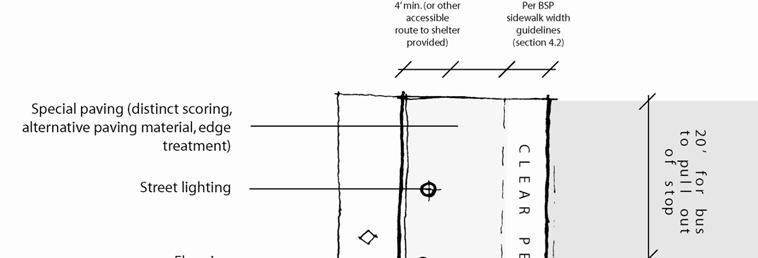
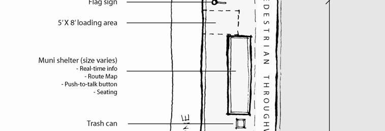
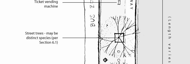
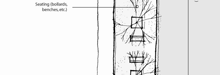
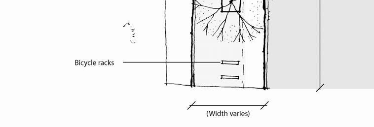
62 Attachment L 10/14/2009 Figure L.1. Layout of Transit Stop (typical) L 5
63 Attachment L 10/14/2009 Design by Type of Transit Route Transit stops on LRT, BRT, or other Rapid Network corridors and at major transfer points should include a greater level of features and amenities than other locations. LRT, BRT, and other special lines should be designed to have a distinct identity and be branded so that they are clearly unique from standard transit stops. Special treatments for transit stops along these lines may include special signage, unique transit shelters, TVMs, special paving or landscape treatments, better-quality materials, and higher numbers of amenities at each stop. At major transfer stops, stop design should facilitate clear, safe and comfortable transfers. Designs may include wayfinding signs, real-time transit information, a clear path of travel between stops, a consistent paving treatment, or other visual cues to link facilities. Appropriate pedestrian safety measures, such as high visibility crossings, curb extensions, or signal timing that prioritizes pedestrians such as leading pedestrian intervals (see Section 5.1) should be prioritized at intersections that are major transfer points. The City should consider a specialized crosswalk marking at major transit transfer points. See Figure 5.XX for appropriate amenities by type of transit route. Table L.1. Streetscape Amenities by Type of Transit Route Type of Transit Route LRT, BRT, Rapid Network Local Network Community Network Special services Appropriate Amenities 1 (General) Flag sign, trees or containerized planters, lighting, special paving, seating (formal or informal), trash cans, bicycle racks, wayfinding information, realtime transit information, transit shelters and seating (at major transfer points) Flag sign, transit shelter, real-time transit information, trees or containerized planters, lighting, trash cans Flag sign, trees or containerized planters, lighting, trash cans Share stations with above 1 As appropriate per guidelines L 6


64 Attachment L 10/14/2009 Figure L.2. Transit Stop (Rapid Network) L 7
 by avoiding the need for transit vehicles to exit and re-enter the flow of traffic at each stop.")
65 Attachment L 10/14/2009 Figure L.3. Transit Stop (Local Network) Transit Bulb-Outs (Bus Bulbs) Bus bulbs are curb extensions that serve a transit stop. Bus bulbs improve transit performance (in most locations) by avoiding the need for transit vehicles to exit and re-enter the flow of traffic at each stop. They also allow for easier accessible boarding as the bus can align directly with the curb. Bus bulbs improve pedestrian conditions by providing extra space for waiting and passing pedestrians and providing a space to locate transit shelters out of the way of pedestrian flow. Placement Bus bulbs should be considered on all streets with side-running transit and a parking lane, except: Where there is a peak period tow-away parking lane L 8

66 Attachment L 10/14/2009 Where there is a desire to have a queue jumping lane for buses At near side stops with heavy right turn movements Bus bulbs should be prioritized: On Rapid Network lines and major transfer points Where existing sidewalk width is too narrow to accommodate a transit shelter, or where pedestrian through travel is constrained Where transit performance is slowed significantly due to the time delays caused by reentering traffic flow, and a bus bulb will mitigate this problem. Guidelines Bus bulbs should follow the transit stop layout guidelines above. They should follow the curb dimension guidelines for curb extensions specified in Section 5.3. Bus bulbs should be long enough to accommodate all doors of transit vehicles that will load and unload at the curb extensions plus an additional 5 feet of maneuvering space. Where there is frequent service, such as on BRT or Rapid Network lines, they should be long enough to accommodate two or more vehicles, with a 5 space in between. Where bus bulbs are provided, streetscape elements including street trees may continue along the same alignment as the rest of the block. The bus bulb may use special paving treatments or distinct tree species to distinguish it from the adjacent sidewalk. Figure L.4. Bus bulb L 9
67 Attachment L 10/14/2009 Transit Boarding Islands Transit boarding islands are waiting areas located on a median in the roadway rather than on the sidewalk. Transit boarding islands can improve transit vehicle performance where vehicles run in the center lane, and do not have to exit and re-enter the flow of traffic at each stop. On multi-way boulevards with transit running in center lanes, transit stops should be placed on side medians that is, the medians should act as transit boarding islands. Transit boarding islands may also improve pedestrian conditions by locating the transit waiting area and transit shelter outside of the primary sidewalk. However, sidewalk stations are typically preferable to boarding islands for pedestrians as they are connected to the primary pedestrian system and adjacent to land uses and activities boarding islands should only be used where transit runs in center lanes. Layout and Amenities Transit boarding islands should follow the transit stop layout guidelines above. They should follow the guidance for medians in Section 5.3. In addition, transit boarding islands should use the following guidelines: Amenities such as shelters, seating, signage poles and ticket vending machines should have a small profile and be arranged along the back edge of the median. Transit shelters should be transparent and should leave 4 feet of clearance in front; this may require removing the sidewalls of the shelter to enable people to pass in front of the shelter. Boarding islands should include dividers between the island and side travel lanes between the island and the curb. Dividers should be designed to contribute to the overall aesthetic of the station. Where traffic speeds and volumes are low, dividers may not be necessary. Boarding islands may include low plantings at the back end of transit boarding islands beyond the pedestrian waiting area Dimensions Transit boarding islands should be at least as long as the distance between the front of the vehicle and the rear-most door plus 5 feet. At stops where two or more vehicles are expected to stop simultaneously, the island should be large enough to accommodate all vehicles with 5 feet of space between each pair of stopped vehicles. Transit boarding islands must include a standard 5-foot wide by 8-foot long clear loading pad for buses to extend their ramp or lift for persons with disabilities to board, or other accessible facility, such as a raised platform with ramp. The median should be designed so that doors used for accessible boarding align with the boarding area. Pedestrian Access Transit boarding islands should have a crosswalk with curb ramp access at one end, at a minimum, connecting to the sidewalks of the street. The boarding island may serve as a pedestrian refuge for street crossings. In addition, the design of transit boarding islands may employ the following treatments to L 10


68 Attachment L 10/14/2009 enhance the design of transit stops, calm traffic in the vehicle lane between the boarding island and sidewalk, and visually connect boarding islands to the sidewalk: Provide a raised or high visibility crossing connecting to one end of the platform, on appropriate street types (see Section 4.1) Pave the side lane in concrete or other special paving to distinguish it from center lanes Create a single-surface zone including the sidewalk, side lane, and boarding island, where traffic speeds and volumes are low. Shared surface treatments should follow the guidelines in Section 5.8. Figure L.5. Transit Boarding Island (from BSP Draft for Public Review) Additional Transit Operations Considerations Bulb-outs on side-street crossings should be prioritized on transit routes to enhance pedestrian safety and transit operations. At signalized intersections, bulb-outs can extend green time available for transit on the major street by reducing pedestrian crossing times on the cross street. L 11
69 Attachment L 10/14/2009 At transit stops, bulb-outs should be full-length bus bulbs, and not a standard corner bulb, as it can be difficult for a bus to exit or re-enter traffic around a standard corner bulb-out. Traffic calming devices on bus routes should be compatible with bus operations (see Section 5.7: Traffic Calming). In particular, strategies involving vertical and horizontal deflection that could affect transit on- performance and rider comfort should not be used, particularly on Rapid and Local routes. Effective time corner radii should balance the necessity to accommodate transit vehicles with the need for safe pedestrian crossing conditions (see Section 5.2: Corner curb radii). L 12
70 Attachment M 10/14/2009 * This section would be added as new guidelines in Chapter 5 (Section 5.5, page 132) of the Draft Better Streets Plan. Follow the link to see the original chapter. New Guidelines Subway Entrances and Vent Shafts Subway entrances and vent shafts (where applicable) take up significant amounts of sidewalk space and must be designed accordingly. They also provide an opportunity to create distinctive design along major transit and pedestrian corridors. Subway entrances and vent shafts should abide by the following guidelines: o Subway entrances and vent shafts should be located out of the sidewalk area, within buildings (as part of joint development) or in off sidewalk parks or plazas wherever possible. o Where subway entrances or vent shafts are located in the sidewalk, they should be placed outside of the path of travel and leave sufficient clear width for the street type. In many cases, this may mean adding a curb extension and locating the entrance or vent shaft on the bulb out. o Subway entrances should include a railing or wall around the opening, high enough to prevent people from falling into the opening, but low enough to see over (3 to 4 feet in height). The wall may be topped with decorative fencing or other visually permeable element. o Subway entrances should include canopies to provide cover from rain. o Subway entrances and vent shafts should incorporate unique design that is specific to the particular transit line, giving the corridor as a whole a unique and recognizable design character. M 1
71 Attachment N 10/14/2009 * This section would replace the existing text on Shared Streets in Chapter 5 (Section 5.8, pages ) of the Draft Better Streets Plan. Shared Public Ways would also be added as its own street type. Follow the link to see the original chapter. Revised Guidelines Shared Public Ways PURPOSE Shared Public Ways are dedicated public rights of way, primarily designed for pedestrian use, and which permit vehicles and bicycles to share the open space. Shared Public Ways: o o o o Prioritize use of the street for pedestrians and public space over vehicular through travel; Calm vehicle traffic to minimize hazards to pedestrians and nuisances to neighbors; Accommodate small numbers of vehicles at low speeds as necessary for local access to building entries and driveways, on street parking, loading, service and emergency access, and deliveries; and Provide clarity as appropriate for people with visual impairments regarding the shared pedestrian/vehicular nature of the space. The character of a Shared Public Way may vary, from quiet, residential only lanes (Pedestrian Priority Lane), to mixed use residential and pedestrian oriented commercial streets without transit (Pedestrian Priority Mall) or with public transit (Transit Mall), as defined below. In all of these cases, Shared Public Ways prioritize pedestrian use of the entire right of way while allowing occasional slow moving vehicles to access local land uses and parking (both on street and off street) in shared areas and provide necessary services. Shared Public Ways may be designed with special paving, a variety of amenities, landscaping, and seating, and pockets of on street parking, to create a safe environment that encourages public recreational use and socialization. They are designed to slow occasional vehicle access and permit passenger loading zones and limited parking that directly serve the land uses along the route. They are especially valuable, and should be prioritized, in neighborhoods with limited opportunities for public open space. Shared public ways may be considered on streets that: - Do not have parking garages with greater than 100 parking spaces; - Have through traffic of fewer than 100 cars per hour; and - Do not have transit service. On streets that do not meet all of these criteria, shared public ways may still be appropriate pursuant to additional study and environmental review. Where shared public ways are implemented, they should follow the design guidelines in this section. N 1
72 Attachment N 10/14/2009 DEFINITIONS 1. Detectable Warning means a standardized surface or feature built into or applied to walking surfaces or other elements to warn visually impaired persons of hazards in the path of travel. Only approved DSA/AC detectable warning products and directional surfaces shall be installed as provided in the CCR, Title 24, Part 1 Articles 2, 3, and 4. Refer to CCR, Title 24, Part 12, Chapter 12 11A and B for building and facilities access specifications for product approval for detectable warning products and directional surfaces. 2. Gateway means a constrained vehicular entry into the Shared Public Way. These are composed of physical elements that serve to provide both visual and physical cues to vehicle drivers that they are entering a Shared Public Way. Gateways serve as traffic calming devices. 3. Hazardous Vehicular Area 1 means a public right of way, vehicular street, alley driveway with a 15 mile per hour or greater speed limit; 4. Pedestrian Only Zone means a portion of the Shared Public Way dedicated to pedestrian use a. Exception: driveways providing access to single or low vehicular volume, residential or commercial business parking garages are permitted to cross through the Pedestrian Only Zone. Advisory: Primary access to shared or common garages should be located away from Shared Public Ways and onto alleys or streets designed for more regular automobile use wherever possible. 5. Pedestrian Priority Lane means a Shared Public Way located in a predominately residential block(s) and which may serve incidental, small business or commercial uses. 6. Pedestrian Priority Mall means a Shared Public Way located in a predominantly commercial block and requires a need to serve adjacent commercial and other land uses. 7. Shared Zone means the portion of the Shared Public Way that is utilized by pedestrian, bicyclists and vehicles. 8. Shared Public Way means dedicated public rights of way, primarily designed for pedestrian use, and which permit vehicles and bicycles to share the open space. By definition and through design criteria, Shared Public Ways are not hazardous vehicular areas, including Pedestrian Priority Lanes, Pedestrian Priority Malls, and Transit Malls. 9. Transit Mall means a Shared Public Way similar to a pedestrian priority mall, but that also includes transit vehicles. 1 The term hazardous vehicular areas is taken from the Americans with Disabilities Act Accessibility Guidelines and the California Access Compliance Reference Manual (Title 24): however, the term is undefined in these documents N 2
73 Attachment N 10/14/2009 POLICIES 1. Shared Public Ways will be designated public rights of way that may or may not be accepted for maintenance and liability by the City and County of San Francisco s Department of Public Works. 2. The design, engineering and construction of Shared Public Ways shall meet or exceed the criteria of the all applicable Public Works Codes. 3. The design of Shared Public Ways shall meet or exceed the US Access Board s Revised Draft Guidelines for Accessible Public Rights of Way November 23, 2005, located at board.gov/prowac/draft.htm. These guidelines shall be considered a best practice rather than a prescriptive requirement. 4. Vehicles and bicyclists shall yield to pedestrians. Vehicle speed shall be no more than a maximum of 10 miles per hour. Signage shall be provided to indicate this requirement. 5. Shared Public Way design elements, features and materials shall be selected for ease of maintenance, among other criteria. This criterion includes elements that serve pedestrian spaces, visual / tactile queues and traffic calming measures. Federal and State law requires that accessibility features provided for individuals with disabilities be maintained. 6. Maintenance: Maintenance of Shared Public Ways may be the responsibility of the adjacent property owners, the City of San Francisco, or some partnership thereof. Issues in definition of maintenance responsibilities and roles include the scope of Shared Public Way features, zones and elements requiring maintenance, the assumption of liability related to the scope of these features, zones and elements, a partnership agreement of maintenance equipment type and storage location, and the use of encroachment permits as a means of establishing responsibilities for the parties involved in maintenance. 7. Public reviews: Where City agencies engage in the process to develop, design and or accept Shared Public Ways, they shall seek public comment on the project. Due to the unique conditions of each potential Shared Public Way, public review may need to occur on a project by project basis. The public review shall solicit participation and input by individuals with disabilities and groups that represent individuals with disabilities, including those individuals whom are blind or have low vision. N 3


74 Attachment N 10/14/2009 DESIGN CRITERIA 1. Design of Pedestrian Areas. Shared Public Ways should be designed to emphasize their pedestrian and public open space character, and to differentiate them from traditional streets and vehicular ways. Strategies to emphasize pedestrian and public open space include: a. Some form of visual / detectable cue shall be provided at the transition from a conventional sidewalk along a perimeter street as it intersects the entry or driveway providing access to a gateway of a Shared Public Way. Figure N.1. Detail of transition from conventional street to Shared Public Way b. Pedestrian only Zones along the Shared Public Way are recommended when the Shared Public Way serves common use parking garages and /or through traffic where the rightof way is greater than 15 in width. Pedestrian Only zones may merge with pedestrian plazas and parks. Figure N.2. Pedestrian only and shared roadway zones of a Shared Public Way c. Use of alternative paving materials or distinct, coherent paving patterns in contrast to that used for traditional streets, lanes or alleys. The Pedestrian only Zone and Shared Zones should appear as an integrated open space of coherent pattern of design, materials, and colors. N 4
75 Attachment N 10/14/2009 d. Paving textures should be smooth and vibration free, and should follow Better Streets Plan Guidelines. Contrast in material textures is recommended for Pedestrian Only Zones from that used in Shared Zones (see #2, below) and to indicate where pedestrians may safely travel within the Shared Zone if continuous pedestrian travel is impeded in other portions of the Shared Public Way. Where the texture of surface materials used in vehicular areas is heavy or coarse enough to impede bicycle or wheelchair circulation, a continuous pedestrian path of a minimum 48 inches wide of smoother materials shall be used throughout the Shared Public Way to lessen vibration impacts on individuals using wheelchairs. e. Where Pedestrian only Zones are utilized, color and contrast is recommended for a majority of the paving materials in the Pedestrian Only Zone compared to that used in the Shared Zone. f. To promote active or passive recreational activities, small plazas or vehicle free spaces are recommended to be located adjacent to the Shared Zone that may alternate from side to side to create chicanes, or be placed between passenger loading zones, driveways or parking spaces. g. Intermittent or regular temporary use of Shared Public Ways is recommended that may require temporary encroachment or closure of the space to vehicular use. Temporary events may include sports courts, block parties, farmer s markets, bazaars, café dining spaces or neighborhood picnics. h. Use of landscaping, seating and other streetscape amenities or furniture is encouraged, and should be located and spaced in a way that allows visual permeability and barrier free pedestrian movement through the entire Shared Public Way even when vehicles are present. i. Where the path of Shared Public Ways lead to curbs, crosswalks and streets, curb ramps with detectable warnings shall be provided. 2. Visual / Tactile Cues. Visual / tactile cues involving surface and architectural treatments that delineate or demarcate between a Shared Public Way s Pedestrian Only and Shared Zones should not impair the potential use of the entire right of way for a variety of recreation and leisure purposes. a. Where Pedestrian Only Zones are planned, delineation shall be provided that defines the boundary between Pedestrian only and Shared Zones. These boundaries serve as both visual and tactile detection systems for the pedestrian, particularly individuals with disabilities. Advisory: Visual / tactile cues may serve the specific needs of individuals with different types of disabilities. Visual queues serve individuals with low vision. Tactile queues may serve as means for wayfinding as a cane detectable edge, shoreline or pathing. The type and use of treatments is dependant upon the context and uses which may occur in the Share Public Way. N 5
76 Attachment N 10/14/2009 Per California Building Code (section 1133B.8.5 if a walk crosses or adjoins hazardous vehicular areas, and the walking surfaces are not separated by curbs, railings or other elements between pedestrian areas and vehicular areas, the boundary between the areas shall be defined by a continuous detectable warning which is 36 inches minimum wide and complying to DPW and State of California technical standard. As noted in definitions, Shared Public Ways are not hazardous vehicular areas, and contain restrictions that mitigate this issue. Curb ramps with detectable warnings are required at pedestrian crossings that intersect raised curbs, if adjacent to Hazardous Vehicular Areas. b. A variety of materials, treatments and objects may be incorporated into creating visual / tactile cues. Combinations of elements are frequently used to create a more vibrant environment. Some elements used as visual / tactile cues include but are not limited to the following: (1) Changes of material texture (cobble or roughened surfaces at Shared Zones contrasting to smoother surfaces at Pedestrian Only Zones, or use of cobbled stone bands between Pedestrian Only and Shared Zones; (2) Changes of material color and contrast (light on dark or dark on light); (3) Use of ½ maximum beveled transitions in surface treatment; (4) Use of caning detectable wayfinding or pathing materials (tactile tiles, ½ inch maximum height material ridges or domed material, etc); (5) Landscaping and raised landscaping planters; (6) Street furniture such as benches, seating ledges, trash cans signage pylons; (7) Bollards, railings and other architectural elements that do not necessarily serve as street furniture; (8) Vertical materials or objects should have color or visual contrast with ground surface materials; (9) Temporary or movable objects, such as swinging gates, movable planter boxes or retractable bollards. Advisory: The use, design and placement of visual / tactile cues should permit effortless permeability of pedestrian circulation between the Pedestrian Only Zone and the Shared Zone. The spacing of vertical objects may serve to prohibit vehicles from entering the Pedestrian Only Zone or other open space plazas or park areas. The placement of vertical and/or caning detectable materials should be aligned to reinforce edges and shoreline path markings. The spacing of these vertical objects should allow for continuous and unencumbered pedestrian movement along a Shared Zone even when vehicles are present, and support the overall use of the Shared Public Way as usable Open Space. c. The design of visual/tactile queues between Pedestrian Only and Shared Zones should be consistent with the Better Streets Plan. The Better Streets Plan contains many N 6
77 Attachment N 10/14/2009 elements of required accessible design, best practices that reflect pending accessibility regulations and concepts of Universal Design. Advisory: Examples of design elements that serve accessible environment include but are not limited to: clear width of accessible routes, avoiding protruding object hazards, use of accessible surface materials, caning detection, seating, bus stops and clear floor or ground areas at operational controls such as pedestrian crossing controls. d. Transit Malls must provide detectable warnings (or other detectable element such as a curb, raised planter, or other architectural barrier) between pedestrian areas and public transit lanes (bus lanes, light rail tracks, and the like). Detectable warnings shall comply to DPW standards for detectable materials. 3. Vehicular traffic calming strategies. Shared Public Ways shall contain traffic control and traffic calming strategies. A variety of materials, treatments and objects may be incorporated into creating traffic calming strategies. Some elements used as vehicular traffic calming strategies include, but are not limited to, the following: a. Gateways. Gateways are constrained vehicular entries into the Shared Public Way. These are composed of physical elements that provide visual, material and sensory cues that calm traffic and induce slower vehicular travel speeds. Gateway elements may include but are not limited to: b. Narrowing the entrance to the Shared Zone from the street. c. Raising the driveway entrance level to the level of adjacent sidewalks such that vehicles and bicycles must ascend a driveway apron to access the Shared Public Way. Driveways shall conform to DPW standards and not reduce the minimum required width for accessible routes along sidewalks. d. Providing gateway elements such as flanking raised planters or vertical pylons or temporary element such as motorized gates or retractable bollards. e. Signage posting speed limits, instruction to yield to pedestrians and other information, such as name of the public space, or other signage indicating pedestrian priority. (Design considerations for signage should incorporate appropriate aesthetics that reflect the nature and character of the particular Shared Public Way). f. Durable, textural material changes, such as a band of rough cobblestones, storm drainage grates or textural material bands in pavement that provide a sense of low vibration when a vehicle drives over the material. g. Color and material contrast (light on dark, dark on light) changes between street, driveway and Shared Public Way. Advisory: Gateway vertical elements should permit visual permeability in the Shared Public Way and should not visually block sidewalks that cross the driveway. N 7
78 Attachment N 10/14/2009 Some form of visual / detectable cue shall be provided at the transition from a conventional sidewalk along perimeter street as it intersects the Gateway entry or driveway providing access to the Shared Public Way. Speed bumps or similar obstructions should be avoided as they may adversely affect vehicle drivers and passengers with spinal cord disability or injury. To accommodate wheelchair and scooter users who would be adversely affected by materials that would cause excessive vibrations, smooth texture pathing should be provided through textural material bands of materials such as rough cobble stones or deep textural impressions in materials. The direction and size of openings in storm drainage grades are limited under accessibility codes and regulations. 4. Traffic Calming within the Shared Public Way. The Shared Public Way should contain material and visual elements that provide traffic calming and induce reduced vehicular speed. Traffic calming elements within the Shared Public Way may include but are not limited to: a. Textural and color contrast changes in materials between Pedestrian Only and Shared Zones. Bands of textural materials can be used to provide vehicle vibration and it travels through the Shared Zone. (Smooth surface paths through these areas and smooth surface multiuse spaces are recommended for pedestrian and recreational use. Smooth surface paths through rough textural materials serve the needs of wheelchair users and those with ambulatory disabilities). b. Raised planters, bollards and street furniture that provide containment of space where vehicles are permitted. The same elements can provide intermittent constrictions of the width of Shared Zones that serve to slow vehicle speed. Streetscape amenities should be located and spaced in a way that allows visual permeability and barrier free pedestrian movement through the Shared Space. c. Introducing serpentine pathways for vehicle and bicycle travel, employing horizontal shifts (chicanes) through placement of landscaping, bollards, street furniture, parking and other streetscape elements, while preserving unencumbered pedestrian travel. d. Placement of small plazas or vehicle free spaces adjacent to the Shared Zone. These spaces may be placed on alternate sides of the Shared Zone to create chicanes, or placed between parking or passenger loading zones, while providing space for active or passive recreational and socializing activities. e. Avoid locating primary entrances to shared or common parking garages on the shared public way wherever possible. 5. Drainage. Shared Public Ways should be designed to drain away from buildings, either toward the center of the street, with a side running gutter on either edge of the central space, or to other storm water drainage features (e.g. rain gardens). N 8
79 Attachment N 10/14/2009 a. Where trench drains are provided, drains should leave openings of no greater than 1/4 per accessibility guidelines. b. Shared Public Ways should follow Better Streets Plan guidelines for stormwater facilities. N 9


80 Attachment N 10/14/2009 Figure N.3. Site Plan of a Shared Public Way N 10
81 Attachment O 10/14/2009 * This section would be a DPW policy, reflected in Chapter 6 (Section 6.1, pages ) of the Draft Better Streets Plan. Follow the link to see the original chapter. Revised Guidelines Tree Planting [DRAFT new DPW Director s Order on Tree Planting] CITY AND COUNTY OF SAN FRANCISCO Department of Public Works ORDER NO. 169,946 PURSUANT TO ORDINANCE NO , REGULATING THE PLANTING, MAINTENANCE, OR REMOVAL OF TREES AND LANDSCAPE MATERIAL ON PUBLIC SIDEWALK AREAS AND SUPERCEDING ORDER NO. 170,735 AND NO. 169,946. I. PURPOSE A. Objective. Planting street trees and landscaping in the public right of way enhances the physical, ecological, and cultural aspects of the city. Because street trees are the most important organizing element of the streetscape environment, appropriate tree species selection, location and design of the planting site is essential. Proper tree selection and planting will ensure the healthy growth and longevity of trees, enhance streetscape character, and maximize the City s investment. B. Authority. Article 16 of the Public Works Code authorizes the Director of Public Works to regulate the planting, maintenance, or removal of trees and landscape material on the public sidewalk. This Department of Public Works (DPW) Order provides detailed guidelines regarding tree and landscape plantings in the public right of way. These guidelines are intended to provide sufficient information for plan development and submission. **Please note that all permit applications are reviewed on a case by case basis, and the Department must approve tree and landscape applications before any installation begins. C. Relation to Sidewalk Landscape Permit. Street trees and landscaping are both elements of the city s urban forest. Generally, this DPW Order provides O 1
82 Attachment O 10/14/2009 guidance on placement of street trees and the size and dimensions of tree planters. In many cases, the City encourages tree basins larger than those recommended in this Order so as to allow landscaping and increased permeability within the right of way. A sidewalk landscape permit is required for planters, with or without a street tree, that are sized larger than the standard dimensions included in this Order. II. STREET TREE AND LANDSCAPE MATERIAL PERMIT APPLICATION AND APPROVAL PROCESS A. Adding or removing a tree. Contact DPW, Bureau of Urban Forestry, to request a permit to plant or remove trees or landscape material on a public sidewalk. The application process is summarized in the following flow chart: A removal permit is required for removal of any tree (alive or dead) in the public right of way, and certain protected trees on private property. See Section 810 of Article 16 of the Public Works Code regarding Significant and Landmark trees. The Department of Public Works may not grant all tree removal permit applications. A DPW certified arborist will evaluate the tree and determine if it is healthy and structurally sound. In most cases a tree O 2
83 Attachment O 10/14/2009 removal permit will not be granted if the tree is healthy and structurally sound. The Department will typically approve a removal permit application for tree removal in the following cases: i. If the tree is unhealthy, and not likely to recover, or has structural wounds or deficiencies that represent a potential public safety hazard, or if the tree is dead or dying; ii. If the applicant proposes to relocate the existing tree at the same property and the Department determines the transplant is likely to succeed. In select cases if the tree proposed for removal can be replaced with a tree (or trees) that matches or exceeds the canopy and trunk diameter of the tree to be removed, the Department may grant the removal application. The canopy and trunk diameter of the replacement tree(s) must match or exceed that of the tree to be removed at the time of planting. If the Department approves a tree removal permit application, a notice is placed on the tree, as described in Sec. 806 (a) of Article 16 of the Public Works Code. Members of the public can appeal the decision and a public hearing will be held by the Department. B. Fee schedule for street tree activities: i. A street tree removal permit fee, as described in Sec.806. (b)(3) of Article 16 of the Public Works Code, is payable upon submittal of the application. Contact DPW, Bureau of Urban Forestry for a fee schedule and application. ii. An In Lieu planting fee is required, as described in Sec.802. (h) of Article 16 of the Public Works Code, for each tree not planted pursuant to Section 143 of the Planning Code, for existing trees O 3
84 Attachment O 10/14/2009 removed without replacement, or for empty tree basins not planted. C. Enforcement. Pursuant to Sec. 118 of the Public Works Code, violators of this order may be subject to criminal, civil or administrative penalties. D. Exceptions. Exceptions due to hardship or unusual circumstances may be submitted for approval to DPW. DPW will conduct reviews on a case bycase basis. III. SELECTING AN APPROPRIATE TREE SPECIES Objective. The selection of tree species and their placement in the public rightof way should be consistent with the goals of a particular street. Ceremonial streets, major throughways, commercial streets and other streets important to the city pattern should use formal, consistent planting palettes chosen for their distinct design qualities to provide strong aesthetic character and facilitate place recognition. Neighborhood residential or smaller streets may use a more diverse, less formal planting palette to indicate neighborhood preference and create a rich planting variety. On DPW maintained streets, the Bureau of Urban Forestry may require specific tree species. B. Guidelines. Climate appropriate trees are encouraged While evergreen trees are preferable for stormwater benefit, deciduous trees allow light to penetrate to more active sidewalks in winter months; Trees with columnar form are appropriate for narrower planting spaces such as small streets and alleys, narrow medians, or narrow sidewalks with minimal building setback (some columnar species may be inappropriate due to low branching); Medium sized trees with light to medium density foliage are appropriate on neighborhood residential and commercial streets; Trees with overarching canopies and medium density foliage are appropriate on wider streets, such as mixed use streets, throughways and boulevards. IV. SELECTING AN APPROPRIATE SITE FOR ADDING A TREE A. Spacing. Street tree spacing should be determined by the expected mature size of the tree. Generally, trees should be planted with the following spacing: O 4
85 Attachment O 10/14/2009 Small trees (<20 crown diameter at maturity) should be planted 15 to 20 feet on center; Medium trees (20 35 crown diameter at maturity) should be planted feet on center; Large trees (>35 crown diameter at maturity) should be planted 35 feet on center. B. Clearances from elements on the sidewalk: i. If sidewalk elements interfere with a planting site, it is generally preferable to move the tree site a few feet in either direction than to skip a planting site entirely. ii. When designing a new street or renovating an existing street, effort should be made to locate or relocate utilities and other elements, where feasible, so that the regular tree spacing listed in section IV(A) can be attained. iii. When adding trees to an existing streetscape, movable site furnishings should be relocated, where feasible, to allow for street tree planting at an appropriate spacing listed above in section IV(A). iv. Tree clearance from site furniture: SIDEWALK FURNITURE Utility Boxes Sewers Fire Hydrants Parking Meters Fire Escapes Pedestrian Furniture CLEARANCE FROM SITE FURNITURE* 3 Feet 5 Feet 5 Feet 3 Feet 10 Feet 3 Feet Utility Poles 5 Feet Parking * Sign 3 Feet M Traffic e Sign 5 Feet a surement is from the center of the tree basin to the edge of the O 5
86 Attachment O 10/14/2009 utility. v. Clearances from parking and traffic signs: a) No tree should be planted within 3 feet of an existing parking sign. Consider sign relocation where feasible and approved by the Department of Parking and Traffic. Permitee may be required to pay for the sign relocation costs. Trees within a driver s sight triangle 1 of a traffic sign should have a vertical clearance of the lowest branch at maturity of 14 feet in height. vi. Clearances from street lights: SIZE OF TREE* (at maturity) Small Medium Large CLEARANCE FROM STREET LIGHT No Closer than 9 Feet No Closer than 15 Feet No Closer than 21 Feet *Mature size of tree determined as shown in IV(A), and by the Bureau of Urban Forestry 1 As measured by DPW and MTA. O 6


87 Attachment O 10/14/2009 O 7
88 Attachment O 10/14/2009 C. Maintaining visibility when planting trees or landscape material adjacent to a street intersection: In order to provide adequate safety and visibility at intersections, street trees and landscaping adjacent to intersections should be located per the following guidelines: i. Trees or landscape material on sidewalks or medians should be located to maintain visibility of pedestrians waiting to cross the street; and ii. Trees should be planted no closer than 5 feet from the near side edge of the crosswalk. Landscape material may be planted within this zone as long as it is maintained at less than 3.5 feet in height and meets other landscape permit requirements; and ii. Trees or landscape material on sidewalks or medians should be located to maintain visibility of traffic signals and signs. a) At signalized intersections, a minimum of two traffic signals per intersection should be visible within a 20 degree driver cone of vision from a stopping sight distance determined by the 85 th percentile speed of the street. 2,3 This is known as the driver stopping sight distance zone. b) Trees that fall within the driver stopping sight distance zone should have a vertical clearance of the lowest branch of 14 feet in height at maturity to allow c) Landscape material may be planted within this driver stopping sight distance zone as long as it is maintained 2 Manual on Uniform Traffic Control Devices; in cases where this sight distance cannot be met, an advance warning sign should be used. 3 Where sidewalk signals may be blocked, consider the feasibility of adding a mast arm signal where one does not currently exist. O 8
89 Attachment O 10/14/2009 at less than 3.5 feet in height and meets other landscape permit requirements; and iv. At uncontrolled intersections, trees or landscape material should be located such that oncoming traffic is visible to the crossing vehicle in either direction within driver sight triangles. 4 a) Trees within driver sight triangles should have a vertical clearance of the lowest branch at maturity of 14 feet in height b) Tree species within driver sight triangles should be selected that have a high branching canopy, narrow trunk diameter, and no lower shrubby limbs. c) Landscape material may be planted within the driver sight triangle as long as it is maintained at less than 3.5 feet in height and meets other landscape permit requirements. D. Planting a tree adjacent to a Bus Zone: i. No tree or landscape material should be planted adjacent to a bus zone when the sidewalk, including the curb, is less than 12 feet wide. ii. iii. No sidewalk landscape material or planters will be permitted adjacent to a Bus Zone. Exceptions may be considered by DPW and MUNI on a case by case basis. When the sidewalk is greater than or equal to 12 feet wide, including the curb, each site should be reviewed by DPW and MUNI on a case by case basis. Minimum requirements as follows (please see illustration on next page): a) 8 clear from the face of curb to the edge of the tree grate must be maintained unless otherwise indicated below. This Distance may be reduced to 5 clear from the face of curb to the edge of the tree grate if not interfering with the ADA lift at the front door zone or the rear door. b) Approach Side Bus Stop. Within 35 from the rear of the bus zone, trees may be planted as long as the basin edge is recessed at least 5 from the curb edge. In 4 As measured by MTA and DPW. O 9
90 Attachment O 10/14/2009 remaining bus zone area, trees may be planted if 8 clear from the face of the curb to the edge of the tree grate is maintained. Trees should be set back at least 25 from the inside edge of the crosswalk. c) Exit Side Bus Stop. Trees may be planted within 20 from the rear of the bus zone as long as the basin edge is recessed at least 5 from the curb edge. In remaining bus zone area, trees may be planted if 8 clear from the face of the curb to the edge of the tree grate is maintained. Trees should not be planted within 10 of the inside edge of the crosswalk. d) These requirements are subject to review and change based upon the specific site situation and review by DPW and MUNI. O 10
91 Attachment O 10/14/ Wide Sidewalk: 12 0 Wide Sidewalk: e) When planting a tree within a Bus Zone, an enlargeable basin cover or metal tree grate must be used in the tree basin. An enlargeable tree basin cover allows for the removal of portions of the grate or basin cover as the tree diameter increases, so that the tree trunk does not grow into the tree grate or basin cover. Tree grates or basin covers must be maintained to prevent damage to tree trunks and to prevent tripping hazards from lifted grates or basin covers. f) Clearances. When planting a tree within a Bus Zone, a minimum of 6 clear from the bus shelter must be maintained. If site furniture or other obstructions are movable, consider relocating obstruction(s) to accommodate tree planting. Consolidating newsracks should also be considered. O 11
92 Attachment O 10/14/2009 E. Planting a tree or landscaping adjacent to a restricted parking Blue Zone: No tree or landscape material should be planted adjacent to a restricted parking Blue Zone when the sidewalk, including the curb, is less than 12 wide. If the sidewalk is wider, trees may be planted so long as 8 is maintained clear as measured from the curb. F. Planting a tree or landscaping in a median island: i. Intersection visibility should be maintained as described in section IV(C). ii. Median tree planting and/or landscape material should be reviewed and approved by DPW and MTA. V. GUIDELINES FOR TREE BASIN CONSTRUCTION AND DIMENSIONS A. Description and Intent. The tree basin is the sidewalk area removed for tree planting. The size of the tree basin varies based on many site opportunities and constraints. A larger tree basin provides increased stormwater benefit and also allows more area for root growth, both of which are beneficial for the tree. The tree basin size should also be balanced with available sidewalk area and maintenance needs. B. Placement on Sidewalk. i. A street tree should be planted in the center of the tree basin. In no case may new street trees result in an unobstructed sidewalk width of less than four feet. Trees should be placed in alignment with existing trees. In locations where minimum unobstructed sidewalk width will not be impacted, trees should be setback from the curb. Alignment should be approved by DPW. ii. No street tree planting will be allowed in sidewalks with a width less than 6. Exceptions may be granted on a case by case basis, as approved by DPW. iii. The table included below lists basic tree basin standards. It is recognized that larger basins allow for greater tree health, increased water permeability, reduced sidewalk upheaval by tree roots, and greater opportunities for landscaping. Larger basins and/or rectangular basins, where the dimension parallel to the curb is longer, are encouraged but must be reviewed on a case by O 12
 tree species, at maturity, should be planted as approved by DPW, Bureau of Urban Forestry 7 to 8 3 x 5")


93 Attachment O 10/14/2009 case basis by the Bureau of Urban Forestry and may require a sidewalk landscaping permit issued by the Bureau of Urban Forestry. See also Section I(C). SIDEWALK WIDTH STANDARD BASIN SIZE* 6 to 7 2 x 5 Note: In this basin size, only small (upright) tree species, at maturity, should be planted as approved by DPW, Bureau of Urban Forestry 7 to 8 3 x 5 8 to 9 4 x 5 9 and wider 5 x 5 iv. The diagrams below show standard recommended basin placement for some typical sidewalk widths. Alternate basin sizes and layouts may be approved by DPW on a case by case basis. v. Planters where perpendicular or angled parking exists. In order to prevent the overhang of vehicles from damaging a tree, planters should be recessed from the curb edge such that the tree trunk or center line is located a minimum of 3 feet from the curb edge. It is also possible to locate the tree in alignment with the parking stripe if the above recess is not feasible. Exceptions may be granted on a case by case basis by the Bureau of Urban Forestry. vi. Planters where perpendicular or angled parking is proposed. Where existing trees have been planted within the first 3 feet in from the curb, parking stalls should be demarcated such that O 13
94 Attachment O 10/14/2009 existing trees align with the parking stripes to avoid conflicts with parking vehicles. Exceptions may be granted on a case by case basis by the Bureau of Urban Forestry and the MTA. This dimension may be reduced where bollards or wheel stops are used to protect the tree. B. Tree basin surface and design. i. Basin surfacing. Tree basin grade should be maintained at the existing sidewalk grade. Decomposed granite, approved hardscape, such as a perimeter of brick or paving stones, or a Title 24 approved basin cover, may be installed and must be maintained at the existing sidewalk grade. The basin cover opening should not be greater than 6 inches, or less than 4 inches, to the base of the tree. The tree trunk should be centered within the tree basin. Generally, tree grates and other structural basin covers are discouraged, as over time, they can become a tripping hazard and can interfere with the growth of the tree. ii. Tree guards. Tree guards are generally discouraged but may be appropriate on heavily traveled sidewalks for protection of newly planted trees that are established and no longer require staking. Tree guards must be approved by BUF. iii. Basin railings and edging. Tree basins may be edged with low fences between 6 and 18 in height where sidewalks have a minimum of 4 feet between the tree basin and a building wall. Railings must be maintained so that they do not fall into the sidewalk, allow for water to percolate into the tree basin, and do not contain pointed finials. Railings may be constructed of wood or metal so long as no sharp edges exist. Edging the planting zone with a contrasting material such as cobbles or brick paving is an appropriate design treatment and effectively demarcates the basin edge. Edging must be maintained at grade with the sidewalk. VI. MAINTENANCE GUIDELINES FOR TREES AND LANDSACPE MATERIAL ON PUBLIC SIDEWALKS AND MEDIANS A. Pruning and maintenance guidelines: i. On the pedestrian side of the sidewalk, newly planted trees should not have branches that extend beyond the perimeter of the tree basin below the 8 minimum vertical clearance. An 8 minimum vertical O 14
95 Attachment O 10/14/2009 clearance from the lowest branch of a mature tree should be maintained. ii. On the vehicular traffic side of the sidewalk, the lowest branch should provide a 14 minimum clearance at maturity. iii. Tree or landscape material should not obscure traffic or parking signs/signals or vehicular sightlines. iv. Tree foliage should be maintained to provide a minimum 6 clearance from any public streetlight. v. All tree maintenance work shall comply with Pruning Standards for Public Trees in the City & County of San Francisco, available from the Bureau of Urban Forestry. Article 16 of the Public Works Code authorizes the Department to impose fines and other penalties for excessive pruning. JD vi. The permit holder is responsible for maintaining the trees and/or landscape material in a condition that is safe to pedestrians and vehicular traffic, free of litter and unsightly weeds, and is responsible for maintaining plants with appropriate pruning, watering, and other care as needed, and ensuring that trees and/or landscape material do not encroach into the 48 inch accessible path of travel as described in Section E above. vii. Tree basin grade should be maintained at the existing sidewalk grade. Edward D. Reiskin Director of Public Works Approved: O 15

96 Attachment P 10/14/2009 * This section would be added as new guidelines in Chapter 6 (Section 6.2, pages ) of the Draft Better Streets Plan. Follow the link to see the original chapter. Revised Guidelines Stormwater Elements New Stormwater Tools: Definitions Vegetated Buffer Strips 1 Vegetated buffer strips are sloping planted areas designed to treat and infiltrate sheet flow from adjacent impervious surfaces. They slope away from the impervious surface and are most often planted with grass, though other uniformly distributed plant species are also appropriate. Buffer strips function by slowing stormwater runoff and allowing sediment and other pollutants to settle and infiltrate. Vegetated buffer strips are well suited to treating runoff from roads and highways, roof downspouts, small parking lots, and pervious surfaces. They are also appropriate for the outer zone of a stream buffer, or as pretreatment for another stormwater BMP that provides detention or storage. In addition, they are generally attractive features that tend to be viewed as landscape amenities rather than as stormwater infrastructure. Figure P.1. Vegetated buffer strip Vegetated Gutters 2 Vegetated gutters are very narrow, landscape systems along street frontages that capture and slow stormwater flow. Typically less than three feet wide, green gutters most resemble planters in that they are confined by vertical curbs and have a flat bottom 1 Source: DRAFT San Francisco Stormwater Design Guidelines 2 Source: San Mateo County Sustainable Green Streets and Parking Lots Design Guidebook P 1
97 Attachment P 10/14/2009 profile. Unlike typical planters, however, green gutters are designed to be very shallow with little or no water retention. While infiltration of stormwater is a possibility, the primary purpose of using green gutters is to provide a site design measure using strip of landscaping to help filter out pollutants and slow the flow of water. Figure P.2. Vegetated gutter P 2
98 Attachment P 10/14/2009 Revised Stormwater Tables Figure 6.2: Best Fit for Stormwater Facilities by Street Type (revised) Paving Bioretention Conveyance Other Commercial Residential Industrial and Mixed- Flowthrough Street Type Permeable Paving Rain Garden and infiltration planter Infiltration Boardwalks Swales Channels and Runnels Infiltration and Soakage Trench Downtown Commercial x x x Commercial Throughway x x x x x x Vegetated Buffer Strip Neighborhood Commercial x x x x x x Downtown Residential x x x x x x x Residential Throughway x x x x x x x Neighborhood Residential x x x x x x x Industrial x x x x x x Use Mixed-Use x x x x x x Parkway x x x x x x x x Park Edge x x x x x x x x Special Small Multi-Way Boulevard x x x x x x x x Ceremonial (Civic) x x x Alley x x x x x Shared Public Way x x x x x Paseo x x x x x x Vegetated Gutter P 3
99 Attachment P 10/14/2009 Figure 6.X: Stormwater Facilities by Location in the Right-of-Way (new) Paving Bioretention Conveyance Other Flowthrough Placement Permeable Paving Rain Garden and infiltration planter Infiltration Boardwalks Swales Channels and Runnels Infiltration and Soakage Trench Vegetated Buffer Strip x - Private Driveways or Yards x x x x x covered x Sidewalk x x x x x x x Vegetated Gutter Curb Extension x x x x x x x Parking Lane/Gutter x x x x** x - covered x x** Bike Lane Through Lane Median x x* x* x* x x* x Traffic Circles x x* x* x* x* x* * Site conditions such as street grading may require special engineering ** Best used in locations with few driveways or curb cuts P 4
100 Attachment P 10/14/2009 Revised Stormwater Sizing Criteria Used to say: San Franciscoʹs stormwater performance measures for areas served by separate storm sewers require the capture and treatment of: o The flow of stormwater runoff resulting from a rain event equal to at least 0.2 inches per hour intensity; or o Eighty percent or more of the annual stormwater runoff volume determined from design rainfall capture curves for San Francisco. The maximum drawndown time for stormwater captured during a rain event is 48 hours. Replace with: In separate sewer areas under SFPUC jurisdiction, applicants proposing new or redevelopment projects that either a) disturb 5,000 square feet or more of the ground plane, or b) are subject to San Franciscoʹs Green Building Ordinance, are required to: o Capture and treat the rainfall from a design storm of 0.75 inches using acceptable best management practices (BMPs); And o Complete a Stormwater Control Plan (SCP) demonstrating how the project will capture and treat rainfall from the 0.75 inch design storm. In combined sewer areas, new streetscape projects are not currently required to use stormwater management facilities, but those that elect to do so should implement a stormwater management plan that results in a 25% decrease in the volume of the stormwater runoff from the 2 year, 24 hour design storm. Used to say: ʺUnless a BMP can achieve 100% infiltration of the 100 year storm, it must have an approved discharge location, otherwise it may cause flooding.ʺ Replace with: ʺAll BMPs must have an approved overflow location for discharge. Approved locations are catch basins and outfalls.ʺ P 5
101 Attachment Q 10/14/2009 * This section would be a DPW policy, reflected in Chapter 6 (Section 6.2, pages ) of the Draft Better Streets Plan. Follow the link to see the original chapter. Revised Guidelines Pervious Paving [DRAFT new DPW Director s Order on Pervious Paving] CITY AND COUNTY OF SAN FRANCISCO DEPARTMENT OF PUBLIC WORKS ORDER NO. APPROVING THE USE OF PERVIOUS PAVING SYSTEMS The Department of Public Works (DPW) Bureau of Engineering (BOE) has determined that the use of pervious paving systems, such as pervious concrete, asphalt, pavers, and pavers with open joints would be beneficial to the City s management and treatment of storm water runoff. Based on these findings, the use of pervious paving systems shall comply with the following requirements and criteria. Description of products and materials as well as any test results and reports must be reviewed and approved by DPW/BOE before use. Installation of pervious paving systems is subject to the following restrictions and recommendations: Allowable Use 1. Sidewalks, driveways, park lands, shared streets, plazas, pedestrian and bike paths, and publicly owned open parking lots 2. Parking strips and gutters that are not used as traffic lanes or bus stops 3. Alleyway traffic lanes with prior approval from DPW; and 4. All streets not classified as arterials or collectors Not Allowed for Use 1. On traffic lanes on streets classified as arterials or collectors 2. Concrete bus pads 3. Curbs 4. On sloped areas or steep hillsides with slopes greater than 5H:1V 5. In areas with a previous history of soil or shallow groundwater contamination 6. In gas stations, car washes, and automotive repair shops 7. In areas where there is a possibility of chemical spills Q 1
102 Attachment Q 10/14/ On streets with a history of combined sewer overflows unless as part of a project aimed at eliminating such overflows. 9. In areas with shallow groundwater or seasonal high groundwater (less than 10 feet) if receiving run-on (see the San Francisco Stormwater Design Guidelines for contributing thresholds) 10. Within 20 feet of subsidewalk basements if receiving runoff (see the San Francisco Stormwater Design Guidelines for contributing thresholds) 11. Within 50 feet of domestic water wells if receiving runoff (see the San Francisco Stormwater Design Guidelines for contributing thresholds) Subgrade must meet the following criteria and properties: 1. Subgrade must be constructed to support anticipated vehicular and pedestrian loads for the site. 2. Existing subgrade must be able to demonstrate a minimum permeability rate of 0.5 inch per hour. An underdrain may be used in soils with lower infiltration rate in order to obtain the minimum permeability rate with prior approval from the SF Public Utilities Commission (SFPUC) to connect to the City collection system. 3. Submit test results from a soils boring log to characterize the soil profile and Pilot Infiltration Test (PIT) or double-ring infiltrometer test to characterize permeability. Borings and test pits shall be a minimum of 5 feet in depth for small drainage areas and 8 to 10 feet for larger drainage areas. 4. Submit soil permeability test results and soil reports to DPW Bureau of Engineering, Structural Section, 30 Van Ness Ave., 5 th Floor, Attention Structural Section Manager Pervious paving products and systems shall comply with the following: 1. Product must have proper strength to withstand H-20 vehicular loads and/or pedestrian loads 2. Submit product test results and product reports. 3. Pervious pavement product shall comply with ADA requirements and standards for slip resistance and maximum openings. Maintenance Requirements 1. Pervious pavement shall be cleaned by a mechanical sweeper with a vacuum a minimum of two times per year or as needed to maintain the products porosity. 2. Pervious pavement shall be tested annually to insure proper function. 3. Signed maintenance agreement with DPW, property owner, and/or developer must be in place prior to any construction. WHEREAS, DPW determined that the use of pervious and/or permeable paving treatments is beneficial to the City of San Francisco, the Director of DPW approves its use as described above for future roadway projects. Q 2
103 Attachment Q 10/14/2009 Edward D. Reiskin Director of Public Works APPROVED: RECOMMENDED: Fuad Sweiss City Engineer & Deputy Director of Engineering Peg Divine Bureau Manager Bureau of Engineering DPW/BOE APPROVED: Date DIRECTOR EDWARD D. REISKIN, Q 3
104 Attachment R 10/14/2009 * This section would be added as new guidelines in Chapter 6 (Section 6.2, pages ) of the Draft Better Streets Plan. Follow the link to see the original chapter. New Guidelines Trench Drains I. Introduction Trench drains are commonly used in street and sidewalk areas to convey water and regulate drainage. They may be used on new streets or retrofits to existing streets, at curb extensions, raised crossings, stormwater facilities, curbless streets (shared or pedestrian only), or other places where drainage channels are necessary outside of the standard curb and gutter. In many cases, trench drains may be a cost effective and desirable solution to solve complicated drainage configurations. However, if not properly located and designed, they may present issues with drainage, maintenance, and accessibility. This document describes guidelines and standards for the appropriate use, placement and design of trench drains in San Francisco. II. III. IV. Definitions a. Trench Drain: Covered channel used to convey water through sidewalk or roadway areas. May be covered or uncovered. Process a. Private sponsors seeking to use trench drains in the public right of way must obtain a permit from the Department of Public Works 1. As part of this permit, the project sponsor accepts liability for any claims arising from failure to properly maintain the street improvements. Guidelines a. Drainage i. Trench drains must be designed to carry the 5 year design storm event within the drain and be able to carry excess storm flow to the downstream inlet. 2 1 May require a major encroachment or minor encroachment permit, depending on the overall scope of the improvement project 2 The overall right-of-way, at a corridor level, shall be designed to carry the 100-year storm. On standard streets, this should be carried within the curb-to-curb width. On curbless streets (either shared or pedestrian-only), the entire right-of-way may be used but water must drain away from property lines. Where corridor capacity is reduced by widening curbs and the flooding potential for abutting properties is increased low-impact design stormwater techniques may be used to offset the reduced carrying capacity of the roadway (see Section 6.2 of the Better Streets Plan). This must be modeled on a case-by-case basis to R 1
105 Attachment R 10/14/2009 ii. Trench drains msut maintain standard cross slope of 2% on the sidewalk for positive drainage. iii. In case of larger storm events or a stopped trench drain, the drainage profile of the site should be designed to drain to nearest gutter or other drainage feature, and away from adjacent property lines. iv. Use of trench drains should not diminish the ability of the roadway to convey stormwater; roadways should continue to have positive drainage. b. Maintenance i. Trench drains built by private entities require an encroachment permit through DPW. The applicant is responsible for maintaining the trench drain in good condition, and must sign a standard maintenance agreement. ii. City sponsored projects that include a trench drain must include a standard maintenance agreement with a maintenance plan, to include maintenance requirements, estimated costs, funding plan for maintenance, and requirements for post construction evaluation. Maintenance plans should account for overall slope and drainage of the site, and expected uses and levels of activity (e.g. a sloping site with low levels of pedestrian activity will have a lower maintenance burden than a flat site with significant pedestrian activity). c. Accessibility i. Trench drains that cross the path of travel should be covered with a stable, firm, and slip resistant cover per DPW Director s Order #176,112. ii. Covered trench drains in the path of travel must have an ADAcompliant grate leaving no more than 1/4 gaps. iii. The installation of the trench drain should not result in a noncompliant sidewalk cross slope (no greater than 2%). d. Loading i. Trench drain channels and covers should be designed to have load bearing capacity appropriate to their use (e.g. on sidewalks, designed to pedestrian weight, in roadways, designed for appropriate design vehicle for the street type). e. Design i. Trench drain channels should be a minimum of 8 in width to facilitate drainage and maintenance and the ability of the drainage determine overall carrying capacity of the surrounding area and the potential for local flooding issues; consult with the PUC. Any street flow shall be contained within the street ROW without causing property flooding. R 2
106 Attachment R 10/14/2009 area to carry the design strom flow. Trench drain channels below this width may be considered on a case by case basis. ii. Trench drains and covers should be designed to integrate their visual appearance with the overall streetscape design. iii. Trench drain covers should be safely secured to the trench drain channel but should also be removable for ease of maintenance. iv. Trench drain material shall meet all applicable ASTM standards. v. Connections from the trench drain to the SFPUC Sewer System, if any, will require approval from SFPUC. If the trench drain will connect directly to the sewer system, bypassing the catch basin, a sand trap device will be required to filter sediment before runoff enters the sewer pipe system. R 3
107 Attachment S 10/14/2009 * This section would be added as new guidelines in Chapter 6 (Section 6.3, pages ) of the Draft Better Streets Plan. Follow the link to see the original chapter. New Guidelines Street Lighting Performance Criteria Pedestrian Light Levels The City should set targets for pedestrian light levels on different street types as outlined in the Better Streets Plan. These levels refer to light directed on pedestrian zones such as sidewalks, bus stops, intersections, and bicycle parking areas. Targets for foot candles* (fc) for each Better Streets Plan street type 1 are as follows: o Commercial 1 fc o Mixed Use 0.5 fc o Residential 0.4 fc o Industrial 0.3 fc o Alleys and paseos 0.3 fc o Special varies For high crime or activity areas, higher values may be considered. *Foot candle refers to the distance (in feet) that is illuminated away from the source of light, measured in lumens per square foot. Providing sidewalks with a minimum luminance of 0.5 fc allows pedestrians to detect obstacles, stay visually oriented, and recognize faces from a distance of 13 feet, a minimum distance that brings comfort with regard to normal social contact. Crosswalks should have a minimum of 7.5 fc to illuminate pedestrians in the crosswalk to vehicles. Crosswalk lighting should provide color contrast from standard roadway lighting. Light spacing. In many cases, roadway lighting plus ambient light from buildings is sufficient to meet the suggested pedestrian light levels. In other cases, additional poles and fixtures would be needed to achieve these light levels. On smaller streets and alleys, pedestrian lights alone may be sufficient to light pedestrian areas and the roadway as well. Appropriate spacing and pole height to achieve desired light levels is determined on a case by case basis. 1 Suggested light levels are consistent with ANSI/IES RP-8-00 American National Standard Practice for Roadway Lighting S 1

108 Attachment S 10/14/2009 Figure S.1. Shields on streetlights should be employed to direct light onto streets and sidewalks and away from residences and the night sky Light loss and trespass Pedestrian light fixtures should be positioned between from the ground. Where possible and desirable, pedestrian light fixtures should share existing poles with roadway lighting however, light level and uniformity requirements should take precedence over pole consolidation, which may result in the need to add additional poles. To prevent light trespass and light loss to the night sky, new and replacement fixtures should achieve a semi cutoff light, with less than 5% light loss above the fixture or shield level, with a target of full cutoff (zero light loss above the fixture or shield level). Existing fixtures should be retrofit or replaced to meet the targets above as funding allows. Exceptions may be considered, such as for historical lighting or where uplighting is desirable for security purposes. The City s approved palette of light fixtures should be evaluated and updated to be compatible with the smart controller technology system to be managed by the Public Utilities Commission. Figure S.2. New and replacement fixtures should achieve a semi cutoff level of 5% light loss above the fixture S 2
109 Attachment S 10/14/2009 Color New and replacement lamps should aim for a color rendering index of 75. Existing lamps should be retrofit to meet the above target as funding allows. In pedestrian areas (sidewalks and crosswalks), use a lamp technology that produces blue or white spectrum light. Energy Efficiency New or replacement pedestrian and street lighting should aim to be a minimum of 50% more energy efficient than standard HPS fixtures. New or replacement pedestrian and street lighting should aim for a measurable efficiency of lumens/watt, the efficiency level of today s HPS. Operating Measures New or replacement pedestrian and street lighting fixtures will be chosen to minimize maintenance and operating costs. New or replacement fixtures and lamps must have a minimum lifespan of 50,000 hours. Table S.1. Comparison of Streetlight Technologies Lamp Type Efficiency (lumens/ watt) Color Rendering Index (CRI) Life (hours) 24,000 to High Pressure Sodium 60 to ,000 10,000 to Metal Halide 60 to to 90 20,000 Induction 60 to ,000 50,000 to LED 50 to to ,000 Incandescent 9 to to99 1,000 to 2,000 Figure S.3. Roadway and pedestrian lights should share poles where feasible to achieve desired light levels and uniformity S 3
110 Attachment T 10/14/2009 * This section would be added as new guidelines in Chapter 6 (Section 6.5, page 216) of the Draft Better Streets Plan. Follow the link to see the original chapter. New Guidelines Temporary Private Uses in the Public Realm In addition to permanent public fixtures, site furnishings also include moveable or temporary elements or uses, typically placed in the sidewalk area by private businesses or homeowners. Temporary private uses in the public realm are generally encouraged as they create a lively and colorful street environment, animate public space, and provide eyes on the street. However, they must be designed and located to ensure safety, accessibility, and appropriate maintenance. Temporary elements include: Outdoor café and restaurant seating Merchandise Displays Street food vendors (Pushcarts and peddlers) Street artists These uses are permitted through various City agencies, including DPW, DPH, Police, Fire, Planning, and others. Permit requirements and responsible agencies are summarized below 1. Outdoor café and restaurant seating 2 Outdoor café and restaurant seating (Tables and Chairs) is encouraged to activate the sidewalk environment and encourage economic development. Outdoor café and restaurant seating require a Street Use Permit from DPW (BSM). Tables and chairs should abide by the following guidelines: Tables and Chairs can be placed only on the sidewalk in front of the applicant s place of business The sidewalk in front of the business must retain a minimum pedestrian clear width per the required sidewalk clear widths in Section 4.2. This clearance must be free of all obstacles. Placement of tables and chairs on the sidewalk must not in any way interfere with curb ramps, access to the building, driveways or access to any fire escape. Tables and Chairs are allowed in the frontage zone where sufficient sidewalk width is available. 1 The information in this section is only a summary of actual permit requirements, focusing on streetscape considerations. Prospective permit applicants should read and understand all requirements for the appropriate permits as identified below. 2 T 1
111 Attachment T 10/14/2009 Tables and Chairs may also be permitted in the furnishings zone, on a case bycase basis as determined by DPW. DPW will consider safety (risk from passing vehicles) and accessibility (people crossing the pedestrian throughway) in their review. Tables and Chairs in the furnishings zone are more appropriate on calmer streets or where a buffering element (such as planters or parked vehicles) between the sidewalk and travel lanes exists. Tables and Chairs in the furnishings zone must be located so as to maintain access to parked vehicles, and may not be located on sidewalks adjacent to disabled parking (blue) or passenger loading (white) parking zones. Placement of Tables and Chairs on the sidewalk must include diverters at each end to guide pedestrians away from the occupied area of the sidewalk. Diverters must: o be flush with building at approximately 90 degrees; o be sturdy, stable and have sufficient weight so that they cannot tip over or be blown away by the wind; o be at least 30 inches high and must be solid within 24 inches of the ground; o have contrasting colors so that they are distinctly visible to the visually impaired; and o be removable at the end of business hours. [add graphic: placement of tables and chairs, from existing DPW diagram] In some locations, temporary café and restaurant seating may be located in the parking lane, where there is a program for flexible use of the parking lane. See Section 5.6 of the Draft Better Streets Plan. Merchandise displays 3 Sidewalk merchandise displays (Merchandise Displays) can enliven the pedestrian realm and enhance the viability of retail establishments in commercial districts. Merchandise Displays require a Street Use Permit from DPW (BSM). Merchandise Displays should abide by the following guidelines: Merchandise Displays can be placed only on the sidewalk in front of the applicant s place of business The sidewalk in front of the business must retain a minimum pedestrian clear width per the required sidewalk clear widths in Section 4.2. This clearance must be free of all obstacles. Placement of Merchandise Displays on the sidewalk must not in any way interfere with curb ramps, access to the building, driveways or access to any fire escape. 3 T 2
112 Attachment T 10/14/2009 The top of the display, including stand and merchandise, must be at least 2 ½ above the sidewalk. The top of the display may not be more than 3 10ʺ above the sidewalk nor more than 2 feet or 25% of the width of the sidewalk in front of the building (whichever is less). Display of fruits and vegetables must be protected by an awning, which must extend a minimum of 6 inches beyond the full length and width of display racks. The finish materials used for display merchandise must be smooth, nonabsorbent and cleanable. Street vendors (Pushcarts and Peddlers) 4 Street vendors (Pushcarts and Peddlers) selling food or other items can enliven a district and provide jobs and services. Pushcarts and Peddlers are permitted through the Police Department. Food vendors also require permits from the Department of Public Health. Other City departments may also review permit applications. Permitted Pushcart and Peddlers must abide by the following: Permits are for one location only. Pushcart and Peddler permits may not be issued for a location within 2 blocks or 600 feet, whichever is greater, of an established business which sells the same type of food or other merchandise as the applicant, or of any location currently being operated by a Peddler or Pushcart Peddler selling the same type of food or other merchandise. Pushcart and Peddler locations must: o Leave a minimum of 10 feet of unobstructed space for pedestrian passage on any sidewalk; o Not occupy a space extending more than 4 ½ feet from the curb line of any sidewalk, nor wider than 4 feet, nor extending more than 5 feet above the sidewalk; o Not be within 18 inches of the curb line of any sidewalk; o Not be closer than 7 ½ feet from the sprinkler inlets, wet and dry standpipe inlets, measured from the outer edge of the standpipe bank from the building line to the sidewalk edge; o Not be within 12 feet of the outer edge of any entrance way to any building or facility used by the public including, but not limited to doors, driveways, and emergency exits measured in each direction parallel to the building line at a 90 degree angle to the curb; o Not be on any sidewalk adjacent to a white, yellow, blue, or red zone, or a bus zone; o Not be within 5 feet of any crosswalk or fire hydrant; o Leave unobstructed fire escapes, underneath and perpendicular from the building to the street, 5 feet from both ends of the fire escape; and 4 T 3
113 Attachment T 10/14/2009 o Not be within 5 feet of inflammable liquid vents and fill pipes when tanks are not being filled nor within 25 feet while tanks are being filled. [add diagram: street artists, from existing SFPD diagram] Street artists 5 The street artists program licenses artists to sell their work on city streets. Street artists are permitted through the Arts Commission. Artists must present their work to a screening committee, obtain a certificate licensing them to sell their work, and participate in a lottery to see which spaces they will occupy. The Board of Supervisors sets appropriate locations for street artists. Per Pushcart and Peddler requirements, street artist booths must adhere to the following dimensions: Booths may be no more than 3 wide, 4 long, and 5 high; Booths may not be within 18 of the curb; Booths may not be within 5 of a fire hydrant or crosswalk; Booths may not be within 12 of the outer edge of an entrance or doorway; Booths must maintain at least 10 clear pedestrian pathway. 5 T 4
114 Attachment U 10/14/2009 * This section would be added as new guidelines, combining wayfinding signage and gateways into a single sub section in Chapter 6 (Section 6.5, page ) of the Draft Better Streets Plan. Follow the link to see the original chapter. New Guidelines Signage and Gateways The purpose of wayfinding signage, gateways, and markers is to provide an overall image of a neighborhood or district, mark edges or entry points, and give information about directions, destinations, or the neighborhood in general. Wayfinding and signage plans should be developed on a neighborhood basis, specific to the needs and importance of that district. They are most appropriate to downtown, commercial, or tourist oriented locations, or around large institutions. Other areas should have a lesser degree of informational signs or neighborhood markers, but may include some basic informational signs, or neighborhood markers. Wayfinding signage, gateways, and markers should follow the guidelines already existing in the Draft BSP (e.g. location in the furnishings zone, retain sufficient clear path of travel, etc.). In addition, they should follow the guidelines listed here. Signage and markers include a hierarchy of types, from most prominent and central, to least prominent and more common. A hierarchy of wayfinding signs, gateways, and markers includes: - Gateway markers (neighborhood or district entry elements) - Neighborhood orientation signs - Interpretive signs - Directional/Wayfinding signs - Standard street and transit signs [add graphic: icons of different signage types] Wayfinding signs and gateways require a major encroachment permit from DPW. All signs and gateways should: Minimize the overall number of wayfinding systems in San Francisco, and minimize the overall number of signs necessary and be placed at strategic locations; overuse will dilute their effectiveness and clutter the streetscape. Catch the attention of passers by but complement the overall streetscape design Align with existing site furnishings or be otherwise located out of the path of travel U 1

115 Attachment U 10/14/2009 Include braille and be multi lingual as necessary and appropriate to the specific location Use a graphic design consistent to the overall signage program, including art elements, icons, colors, graphics and font Incorporate neighborhood specific or artistic elements Gateways Gateways are markers or monuments located at the entrance to a district or neighborhood to announce the entry to a particular area, or a transition from one area to the next. Gateways may be a literal gateway (such as the Torii Gate in Japantown), markers on either side of a street (such as the Little Saigon markers), a singular large sculptural or iconic element (such as the sailor s wheel in Fisherman s Wharf), or even a unique landscape feature or plaza. They are generally more artistic or sculptural, and less literal or functional than other types of signage. In addition to guidelines already in the Draft BSP, gateway markers should: - Be located at defined entry points to a district or a neighborhood, or transitions from one neighborhood or district to another. They may also be appropriate at areas where a freeway becomes a surface road, or where there are other significant changes to the roadway, land use, or building form (for example, where a major roadway becomes a quiet residential street). - Be large enough to attract attention and identify the neighborhood entrance. - Incorporate unique artistic, sculptural, or culturally expressive elements appropriate to the particular neighborhood context. Neighborhood Orientation Signs Neighborhood orientation signs provide a central element to provide district or neighborhood information, including the area s name, neighborhood map, list of destinations (such as primary cultural institutions, historical buildings and sites of significance), with a distinctive, coordinated design. Neighborhood orientation signs should: U 2


116 Attachment U 10/14/2009 Be located at key points in the neighborhood, such as at a major transit stop, or a central public space Include directories/maps to guide people to various neighborhood resources Highlight public and private destination points, including shopping, cultural and recreational facilities, public parking and facilities (e.g. restrooms) destinations Use a standardized graphics template, including an icon or logo, bold, large and visible letters and consistent font, color scheme, and graphics Signs may also use new technologies such as interactive and virtual displays with event or other real time information; however, screens or messages with variable graphics should minimize visual intrusion as appropriate to the particular context. Directional/Wayfinding Signs Directional signs give basic wayfinding information to transit and neighborhood destinations with a distinctive, coordinated design. They are typically simpler with less information than a neighborhood orientation sign, limited to place names and directional information. Directional signs should: - Be located at strategic locations such as key corners within the neighborhood or district to direct people to local resources via vehicle, bicycle, or foot - Include destination icons, place names, and directional markers (e.g. arrows) for local destinations on blades or integral to the body of the sign - Use a graphic design consistent with the overall signage program for the neighborhood, including neighborhood orientation signs - Share existing poles where possible and consistent with the signage design, or be designed as an integral streetscape element U 3
117 Attachment U 10/14/2009 Interpretive Signs Interpretive signs give historical, cultural, natural or architectural information about their particular locale. They may be part of a historic trail, identify a particular site where an important event occurred, or describe other aspects of a neighborhood s particular past or present. Interpretive signs should: - Use a consistent graphic design program for the district or neighborhood - Include graphics, photos, and text; provide a bold, strong heading and clear, succinct text - Use a unique, neighborhood specific design that incorporates creative or artistic elements into the overall design. - Interpretive signs may be coordinated with a centralized directory and map. Standard Street and Transit Signs Standard street and transit signs give basic directional information about street names or transit lines. They are typically located on all street corners and transit stops. They should be built to citywide standards for street or MUNI signs. U 4

118 Attachment V 10/14/2009 * This section would be added as a new sidebar in Chapter 6 (Section 6.6, pages ) of the Draft Better Streets Plan. Follow the link to see the original chapter. New Sidebar Screening of Surface Mounted Utilities Surface mounted utilities are often bulky and unattractive elements in the streetscape. Where possible, they should be located outside of the right of way, screened within private parcels. However, in many cases, they will be located in the public right of way. To that end, they should minimize their negative visual impact. Surface mounted utilities (SMUs) require an excavation permit from the Department of Public Works, and must comply with DPW Director s Order #175,566. In addition to the Director s Order and guidelines in the Draft Better Streets Plan (which describe appropriate location in the right of way), SMUs should abide by the following guidelines for screening of SMUs: o SMUs should be painted a neutral color to blend in with background street elements. Alternatively, they may be considered an artistic element in themselves, and boldly painted as part of public art in the streetscape. o Where sidewalk dimensions allow, SMUs should be screened by elements appropriate to the particular street type. o For example, on residential streets, they may be buffered on either side and behind by sidewalk planters with tall, leafy shrubs. Sidewalk plantings should adhere to the guidelines in Section 6.1, and should fit in with the overall planting palette of the street. Buffer plantings should generally be 6 2 in width, and should retain access to the front of the cabinet. o On commercial or mixed use streets, SMUs may be screened by low seating walls, artistic screens, or other elements. Plantings might be incorporated through vertical metal lattices with climbing vines to screen the utility boxes. V 1

119 Attachment V 10/14/2009 Caption: San Diego s Urban Art Trail contains many examples of typically mundane streetscape elements, such as utility cabinets, brightly painted with murals. V 2
Aurora Urban Street Standards For Transit Oriented Developments and Urban Centers
 Aurora Urban Street Standards For Transit Oriented Developments and Urban Centers I. Purpose These standards will be applied to create a safe, comfortable, pleasant and pedestrian-friendly multi-modal
STREETSCAPE CONCEPTS
 STREETSCAPE S CARGO WAY CARGO WAY CYCLE TRACK Streetscape Concepts JENNINGS ST Illustrative Plan EVANS AVE PG&E BAY TRAIL HERON S HEAD PARK The recommended improvements build off the planned improvements
CURBSIDE ACTIVITY DESIGN
 5 CURBSIDE ACTIVITY DESIGN This chapter provides design guidance for separated bike lanes adjacent to curbside activities including parking, loading and bus stops. Typical configurations are presented
Omaha s Complete Streets Policy
 Omaha s Complete Streets Policy (Adopted August 2015) VISION To create great places and enhance our quality of life, the City of Omaha will provide safe, accessible streets for all users. Complete Streets
Chapter 2: Standards for Access, Non-Motorized, and Transit
 Standards for Access, Non-Motorized, and Transit Chapter 2: Standards for Access, Non-Motorized, and Transit The Washtenaw County Access Management Plan was developed based on the analysis of existing
Figure 5-1 Complete Street Zones. Roadside. May include frontage, pedestrian throughway, furnishings and curbside areas.
 Design Guidelines 5 The design guidelines presented in this section provide descriptions related to the form and function of the four Complete Streets zones: roadside, parking, roadways and lanes, median,
complete streets design and construction standards public primer City of Edmonton
 complete streets design and construction standards public primer City of Edmonton introduction Complete Streets are streets for everyone: people who walk, wheel, bike, take transit, or drive. They are
Make Lincoln Highway an economically vibrant corridor that is safe, efficient, and beautiful for local residents and visitors.
 Lincoln Highway Streetscape Plan Stakeholder Workshop #2 Handout Contents Introduction and Project Vision Planning Principles Specific Recommendations including a Proposed Typical Roadway Section Renderings
5 CIRCULATION AND STREET DESIGN
 5 CIRCULATION AND STREET DESIGN This chapter describes circulation and streetscape improvements proposed for the Northwest Chico Specific Plan Area. It includes detailed design specifications for existing
Multimodal Through Corridors and Placemaking Corridors
 68 Multimodal Through Corridors and Placemaking Corridors Corridors have different functions in a region. Some corridors are used to get smoothly and rapidly through a region or to get quickly to major
Item to be Addressed Checklist Consideration YES NO N/A Required Description Complete Streets Guidelines
 Passaic County Complete Streets Checklist - Concept Development Project Name Item to be Addressed Checklist Consideration YES NO N/A Required Description Complete Streets Guidelines Existing Plans Have
1.3 Pedestrian Environments
 SECTION 1: COMMERCIAL DEVELOPMENT 1.3 Pedestrian Environments Design Principle The quality of the pedestrian environment often defines the overall success of a commercial project. Attention to the development
PUBLIC REALM MASTER PLAN
 WESTSHORE BUSINESS DISTRICT PUBLIC REALM MASTER PLAN MASTER PLAN COMMITTEE MEETING MARCH 20, 2013 WESTSHORE BUSINESS DISTRCT PUBLIC REALM MASTER PLAN MACRO-SCALE CONCEPT: A PUBLIC REALM FRAMEWORK DEFINED
S T A T I O N A R E A P L A N
 The Circulation and Access Plan describes vehicle, pedestrian, and transit improvements recommended within the Concept Plan. In order to create and sustain a vibrant business district that provides pedestrian-friendly
Figure 4-10: Pedestrian Improvements Types of Potential Station Area Improvements - Place-Making Improvements
 INCORPORATE FEATURE PAVIN IN CROSSWALK AND INTERSECTION FIELDS Identifies high-priority pedestrian areas and create a station identity through colorful and interesting patterns ADD CURB EXTENSIONS Extending
Active Transportation Facility Glossary
 Active Transportation Facility Glossary This document defines different active transportation facilities and suggests appropriate corridor types. Click on a facility type to jump to its definition. Bike
This chapter describes the proposed circulation system and transportation alternatives associated with
 5.0 Circulation 5.1 OVERVIEW This chapter describes the proposed circulation system and transportation alternatives associated with West Landing, and summarize the information contained in the Existing
Report. Typical Sections. City of Middleton, WI
 Report Typical Sections City of Middleton, WI December 2006 Report for City of Middleton, Wisconsin Typical Sections repared by: Traffic Associates LLC and STRAND ASSOCIATES, INC. 910 West Wingra Drive
Vision: Traditional hamlet with an attractive business/pedestrian friendly main street connected to adjacent walkable neighborhoods
 N D. Focus Area II Vision: Traditional hamlet with an attractive business/pedestrian friendly main street connected to adjacent walkable neighborhoods Transit Road Focus Area II is located in the Hamlet
s a n f r a n c i s c o
 s a n f r a n c i s c o BETTER STREETS PLAN Policies and Guidelines for the Pedestrian Realm F I N A L D R A F T R E L E A S E P A C K E T J U L Y 2 0 1 0 i n s i d e : L E T T E R F R O M M A Y O R G
Bicycle and Pedestrian Advisory Committee (BPAC) November 21, 2013
 November 21, 2013") Bicycle and Pedestrian Advisory Committee (BPAC) November 21, 2013 OVERALL LAND USE CONCEPT Overall Broadway Valdez District: 95.5 acres (35.1 acres right-of ways + 60.4 acres developable land) Plan Subareas:
Bicycle and Pedestrian Advisory Committee (BPAC) November 21, 2013 OVERALL LAND USE CONCEPT Overall Broadway Valdez District: 95.5 acres (35.1 acres right-of ways + 60.4 acres developable land) Plan Subareas:
Proposed. City of Grand Junction Complete Streets Policy. Exhibit 10
 Proposed City of Grand Junction Complete Streets Policy Exhibit 10 1 City of Grand Junction Complete Streets Policy Vision: The Complete Streets Vision is to develop a safe, efficient, and reliable travel
Roadway Classification Design Standards and Policies. Pueblo, Colorado November, 2004
 Roadway Classification Design Standards and Policies Pueblo, Colorado November, 2004 Table of Contents Page Chapter 1. General Provisions 1.1 Jurisdiction 3 1.2 Purpose and Intent 3 1.3 Modification 3
SECTION 1 - TRAFFIC PLANNING
 SECTION 1 - TRAFFIC PLANNING 1.1 TRAFFIC OPERATIONS 1.1.1 Roadway Functional Classification The Multnomah County Comprehensive Framework Plan s Policy 34: Trafficways and the Functional Classification
Community Meeting February 27, 2007 Dorchester Avenue Transportation & Streetscape Improvements Action Plan February 27, 2007
 Community Meeting Tonight s Agenda 6:00 Introductions South Boston/Dot Ave Improvement Study Background 6:15 Consultant Introductions Review of Scope and Schedule Review of Proposed Corridor Wide Guidelines
DRAFT - CITY OF MEDFORD TRANSPORTATION SYSTEM PLAN Roadway Cross-Sections
 Roadway Cross-Sections Medford s roadway cross-section standards apply to new and reconstructed roads. The crosssections take into consideration roadway function and operational characteristics, including
Complete Streets. Designing Streets for Everyone. Sarnia
 Complete Streets Designing Streets for Everyone Sarnia Complete Streets ~ Sarnia ~ 2018 Introduction Our City is made up of a network of streets that we use to go for a walk, cycle to work, drive to the
INDEX. Geometric Design Guide for Canadian Roads INDEX
 Acceleration lane, see Lanes, Acceleration Access, 8.1 Access Management and Functional Classification 8.2 Access Management by Design Classification 8.3 Access Configuration 8.4 Building Set-Back Guidelines
Appendix A: Crosswalk Policy
 Appendix A: Crosswalk Policy Appendix A: Crosswalk Policy Introduction This citywide Crosswalk Policy is aimed at improving pedestrian safety and enhancing pedestrian mobility by providing a framework
Designing Complete Streets: What you need to know
 Designing Complete Streets: What you need to know Getting from this to this. Continuous sidewalk Buffer w/trees Bicycle lane Raised median Buildings close to the street Flexibility in design Design and
APPENDIX A: Complete Streets Checklist DRAFT NOVEMBER 2016
 APPENDIX A: Complete Streets Checklist DRAFT NOVEMBER 2016 Complete Streets Checklist MetroPlan Orlando s Complete Streets Checklist is an internal planning tool for staff to further implementation of
Off-road Trails. Guidance
 Off-road Trails Off-road trails are shared use paths located on an independent alignment that provide two-way travel for people walking, bicycling, and other non-motorized users. Trails specifically along
Executive Summary Route 30 Corridor Master Plan
 Route Corridor Master Plan Project Overview The Route Corridor Master Plan is a coordinated multimodal transportation and land use plan for the entire stretch of Route through East Whiteland Township,
MARTIN LUTHER KING JR. WAY
 OCTOBER 2011 40 Vision and Goals The Martin Luther King, Jr. Way Illustrative Master Plan that follows has been developed through a process of community involvement. It expresses a long term vision for
Bridges and Arizona Crossings
 Circulation and Transportation 5-11 Discovery Street/Barham Drive. Discovery Street is planned 5.4.3 Specific Plan Circulation Improvements to be extended eastward from its terminus at Craven Road Circulation
CHAPTER 16 PEDESTRIAN FACILITIES DESIGN AND TECHNICAL CRITERIA TABLE OF CONTENTS
 CHAPTER 16 PEDESTRIAN FACILITIES DESIGN AND TECHNICAL CRITERIA TABLE OF CONTENTS Section Title Page 16.1 General... 16-1 16.1.1 AASHTO Reference... 16-1 16.1.2 ADA Requirements... 16-1 16.2 Sidewalks...
7/23/2017 VIA . Michael Hanebutt City of Sacramento Community Development Department 300 Richards Boulevard, 3 rd Floor Sacramento, CA 95811
 7/23/2017 VIA EMAIL Michael Hanebutt City of Sacramento Community Development Department 300 Richards Boulevard, 3 rd Floor Sacramento, CA 95811 RE: 65 th Street Apartments (DR17-220) Dear Mr. Hanebutt:
5 Circulation & Parking
 5 Circulation & Parking Downtown Parking & Circulation Strategy. Downtown Wayne has a somewhat disconnected system of local public streets to connect downtown with the residential neighborhoods, and primary
12/4/2016 VIA . RE: Grocery Outlet Del Paso (DR16-328)
") 12/4/2016 VIA EMAIL Ethan Meltzer, Assistant Planner City of Sacramento Community Development Department 300 Richards Blvd, 3 rd Floor Sacramento, CA 95811 RE: Grocery Outlet Del Paso (DR16-328) Dear Mr.
12/4/2016 VIA EMAIL Ethan Meltzer, Assistant Planner City of Sacramento Community Development Department 300 Richards Blvd, 3 rd Floor Sacramento, CA 95811 RE: Grocery Outlet Del Paso (DR16-328) Dear Mr.
Streetscape: Core Shopping District
 Streetscape: Core Shopping District DRAFT DRAFT DRAFT May 00 Core Shopping District: Phase Blue Island s Core Shopping District is located along Western Avenue, between Grove and Union Streets. Streetscape
DESIGN CODE. Enterprise West Harlow London Road North Design Code 21
 DESIGN CODE Enterprise West Essex @ Harlow London Road North Design Code 21 4 MAXIMUM BUILDING HEIGHTS 4.1 Table 4A sets out maximum building height standards for each character area within the LDO boundary.
Chapter 3: Multi-Modal Circulation and Streetscapes
 CHAPTER 3: MULTI-MODAL CIRCULATION AND STREETSCAPES Chapter 3: Multi-Modal Circulation and Streetscapes Overview Streetscape improvements have already been completed for Depot Street between Main Avenue
TRANSPORTATION STANDARDS
 INTRODUCTION LOCAL STREETS ON-STREET PARKING SIDEWALKS STREET LIGHTING STREET FURNISHINGS TRAFFIC CALMING STREET TREES MEDIAN PLANTING BOULEVARD LOCATIONS VILLAGE CENTER STREET LOCATIONS RESIDENTIAL STREET
Footpath design. A guide to creating footpaths that are safe, comfortable, and easy to use
 Footpath design A guide to creating footpaths that are safe, comfortable, and easy to use November 2013 Contents Introduction / 1 Zoning system / 2 Width / 4 Height / 5 Surface / 5 Footpath elements /
M-58 HIGHWAY ACCESS MANAGEMENT STUDY Mullen Road to Bel-Ray Boulevard. Prepared for CITY OF BELTON. May 2016
 M-58 HIGHWAY ACCESS MANAGEMENT STUDY Prepared for CITY OF BELTON By May 2016 Introduction Missouri State Highway 58 (M-58 Highway) is a major commercial corridor in the City of Belton. As development has
CONNECTIVITY PLAN. Adopted December 5, 2017 City of Virginia Beach
 CONNECTIVITY PLAN Adopted December 5, 2017 City of Virginia Beach CONTENTS 1.0 Background & Purpose... 2 2.0 Existing Inventory & Analysis... 3 ViBe District Existing Walking Conditions... 4 3.0 ViBe District
2.0 LANE WIDTHS GUIDELINE
 2.0 LANE WIDTHS GUIDELINE Road Engineering Design Guidelines Version 2.0.1 May 2018 City of Toronto, Transportation Services City of Toronto Page 0 Background In early 2014, Transportation Services initiated
Driveway Design Criteria
 Design Manual Chapter 5 - Roadway Design 5L - Access Management 5L-4 Driveway Design Criteria A. General For efficient and safe operations, access drives and minor public street intersections can be improved
Tonight is for you. Learn everything you can. Share all your ideas.
 Strathcona Neighbourhood Renewal Draft Concept Design Tonight is for you. Learn everything you can. Share all your ideas. What is Neighbourhood Renewal? Creating a design with you for your neighbourhood.
STEERING COMMITTEE MEETING June 17, Streetscape Overview Burlington Comprehensive Master Plan
 STEERING COMMITTEE MEETING June 17, 2015 Streetscape Overview Burlington Comprehensive Master Plan 1 Introduction Slide This slide show was presented to the Burlington Steering Committee on June 17, 2015
10.0 CURB EXTENSIONS GUIDELINE
 10.0 CURB EXTENSIONS GUIDELINE Road Engineering Design Guidelines Version 1.0 March 2017 City of Toronto, Transportation Services City of Toronto Page 0 Background In early 2014, Transportation Services
Ann Arbor Downtown Street Plan
 1 Ann Arbor Downtown Street Plan Public Workshop #1 We know that. 2 Public right-of-way (streets, sidewalks, and alleys) make up 30% of the total District area of downtown. Streets need to provide mobility
A Guide to Great Streets: The Basics. September 25, 2009
 A Guide to Great Streets: The Basics September 25, 2009 Streets are more than connectors, they are the city 2 Streets are the glue that hold a city together 3 Streets are the means in which a city is perceived
TRANSPORTATION COMMISSION Agenda Staff Report
 TRANSPORTATION COMMISSION Agenda Staff Report Agenda Item No. 5.a DATE: JULY 31, 2014 TO: FROM: SUBJECT: TRANSPORTATION COMMISSION COMMUNITY DEVELOPMENT DEPARTMENT - PLANNING DRAFT OLYMPIC CORRIDOR PREFERRED
MOVING PASSAIC COUNTY
 MOVING PASSAIC COUNTY COMPLETE STREETS GUIDELINES OCTOBER 2012 Prepared By: Passaic County Department of Planning and Economic Development with assistance from Parsons Brinckerhoff PASSAIC COUNTY COMPLETE
WHEREAS delivery trucks also pass through the Narrows, into the northern parking lot, to loading docks in the back of the building.
 CEDAR-ISLES-DEAN NEIGHBORHOOD ASSOCIATION ( CIDNA ) RESOLUTION OPPOSING A DRUG STORE DRIVE THRU, AND COMMENDING DORAN COMPANIES FOR PROPOSING MITIGATING AMENITIES INCLUDING NEW LANDSCAPING AND A DEDICATED
UDC Street Cross Sections
 UDC Street Cross Sections Local Street - Downtown Local Street Mountable Curb Local Street Vertical Curb Alley Major Arterial Minor Arterial Residential Lane Residential Collector Residential Collector
A. Arlington County Master Transportation Plan Pedestrian Element B. Arlington County Horizontal Standards H-3.1 Driveway Entrances
 GENERAL 1. Description This standard identifies minimum requirements that shall be met for all accessible ramps in the design and construction of elements for Arlington County Horizontal Design Standards.
Appendix C. TRAFFIC CALMING PROGRAM TOOLBOX
 Appendix C. TRAFFIC CALMING PROGRAM TOOLBOX PHASE I...2 Do Not Enter Sign...3 One-Way Sign...4 Turn Prohibition...5 Pavement Markings...6 Speed Monitoring Trailer...7 Neighborhood Speed Watch...8 Police
Guthriesville Village Manual of Written & Graphic Design Guidelines
 Exhibit B Revisions: May 23, June 21, July 20, September 20, & October 9, 2012 Updated: December 13, 2012; June 27, 2013; February 7, 2014 Outline of Contents: 1. Purpose and Applicability 2. Overall Form
FOCUS AREA 1 - Alberta Avenue Pocket Park 3 (121 Ave and 92 St)
") FOCUS AREA 1 - Alberta Avenue Pocket Park 3 (121 Ave and 92 St) New benches Plant evergreen trees Widen existing sidewalk from 1.5m to 1.8m Marked crosswalk 1.8m wide sidewalk Add pedestrian oriented lights
FOCUS AREA 1 - Alberta Avenue Pocket Park 3 (121 Ave and 92 St) New benches Plant evergreen trees Widen existing sidewalk from 1.5m to 1.8m Marked crosswalk 1.8m wide sidewalk Add pedestrian oriented lights
PEDESTRIAN CIRCULATION & STREETSCAPE DESIGN
 CHAPTER 4 Chapter 4 Pedestrian Circulation & Trails PEDESTRIAN CIRCULATION & STREETSCAPE DESIGN In recent years, the City has constructed new sidewalks and enhanced existing ones in the downtown with brick
Broad Street Bicycle Boulevard Design Guidelines
 Broad Street Bicycle Boulevard Design Guidelines Building from the strategies introduced in the 2013 Bicycle Transportation Plan and community input received thus far, City Transportation Staff have identified
NEWMARKET UPHAM S CORNER
 SOUTH STATION Planning Initiative NEWMARKET UPHAM S CORNER COLUMBIA ROAD (P) FOUR CORNERS/GENEVA Working Advisory Group (WAG) Meeting #5 TALBOT AVENUE MORTON STREET BLUE HILL AVE/CUMMINS HWY (P) RIVER
City of Vallejo Traffic Calming Toolbox
 City of Vallejo Traffic Calming Toolbox June 1, 2013 Final Table of Contents Introduction... 1 Non-Physical Devices... 3 High-Visibility Crosswalk... 3 In Pavement Lighted Crosswalk... 4 Rapid Flashing
PEDESTRIAN ACCOMMODATIONS DPS 201 AT ROUNDABOUTS
 PEDESTRIAN ACCOMMODATIONS DPS 201 AT ROUNDABOUTS WHY THEY WORK FOR PEDESTRIANS IF DESIGNED CORRECTLY Separated sidewalks direct peds to crosswalks Splitter island Slow speed exit Truck apron Crosswalk
What Is a Complete Street?
 Session 5 Charleen Zimmer, AICP, Zan Associates May 5-7, 2010 What Is a Complete Street? May 2010 5-1 Not a Complete Street More of a Complete Street May 2010 5-2 Benefits of Complete Streets Safety for
Lincoln Highway Streetscape Plan Concept Plan
 Lincoln Highway Streetscape Plan Concept Plan November 14, 2014 Introduction This report provides a summary of conceptual transportation, land use, and design recommendations in the Lincoln Highway Streetscape
City of Wayzata Comprehensive Plan 2030 Transportation Chapter: Appendix A
 A1. Functional Classification Table A-1 illustrates the Metropolitan Council s detailed criteria established for the functional classification of roadways within the Twin Cities Metropolitan Area. Table
o n - m o t o r i z e d transportation is an overlooked element that can greatly enhance the overall quality of life for the community s residents.
 N o n - m o t o r i z e d transportation is an overlooked element that can greatly enhance the overall quality of life for the community s residents. 84 Transportation CHAPTER 11 INTRODUCTION Transportation
David Hung, Associate Planner City of Sacramento Community Development Department 300 Richards Boulevard, 3 rd Floor Sacramento, CA
 June 13, 2016 VIA EMAIL David Hung, Associate Planner City of Sacramento Community Development Department 300 Richards Boulevard, 3 rd Floor Sacramento, CA 959811 RE: Fire Station 14 (DR16-128) Dear Mr.
CURB EXTENSIONS BULB OUTS DPS 201 NECKDOWNS
 CURB EXTENSIONS BULB OUTS DPS 201 NECKDOWNS WHY WHEN & WHERE When Limited Sight Distance Pedestrians & Vehicles Vehicles and Signs Want to put two curb ramps in Discourage High speed turning High number
El Camino Real Specific Plan. TAC/CAC Meeting #2 Aug 1, 2018
 El Camino Real Specific Plan TAC/CAC Meeting #2 Aug 1, 2018 Land Use Alternatives Goals and Tradeoffs Parks & open space Housing Retail & services Civic spaces Parking Community gathering spaces 3 Alternatives
C C C
 C-012-001 Thank you for your support for the creation of new public space and nonmotorized access between downtown and the waterfront through the Overlook Walk, the East-West Connections, and the Promenade.
Mission-Geneva Transportation Study Community Workshop 2 July 8, 2006
 Community Workshop 2 July 8, 2006 Small Group Workbook 1 Basic Improvements on Mission Street Streetscape. Pedestrian-scale lighting; landscaping; community art on utility boxes; more (possibly unique)
Guidance. ATTACHMENT F: Draft Additional Pages for Bicycle Facility Design Toolkit Separated Bike Lanes: Two-Way to One-Way Transitions
 ATTACHMENT F: Draft Additional Pages for Bicycle Facility Design Toolkit Separated Bike Lanes: Two-Way to One-Way Transitions This treatment provides a transition from two-way separated bike lanes to one-way
Ocean Park Boulevard Green Street Project Alternatives & Trade Offs
 Planning Commission March 4, 2009 Ocean Park Boulevard Green Street Project Alternatives & Trade Offs Purpose of Tonight s Meeting Review concept plans and options Provide input on alternatives and trade-offs
Chapter 3 DESIGN SPECIFICATIONS
 Brampton PathWays Planning and Design Guidelines 27 Chapter 3 DESIGN SPECIFICATIONS 3.1 CLASS 1 MULTI-USE PATH Off-road multi-use trails are the backbone of the Brampton PathWays Network. They are typically
Agenda. Overview PRINCE GEORGE S PLAZA METRO AREA PEDESTRIAN PLAN
 PRINCE GEORGE S PLAZA METRO AREA PEDESTRIAN PLAN May 28, 2008 Agenda Welcome and introductions Project overview and issue identification Planning context and strengths Design challenges and initial recommendations
TRAFFIC CALMING GUIDE FOR TORONTO CITY OF TORONTO TRANSPORTATION SERVICES DIVISION
 TRAFFIC CALMING GUIDE FOR TORONTO CITY OF TORONTO TRANSPORTATION SERVICES DIVISION CITY OF TORONTO TRANSPORTATION SERVICES DIVISION 2016 TRAFFIC CALMING GUIDE FOR TORONTO TABLE OF CONTENTS Introduction
City of Seattle Edward B. Murray, Mayor
 City of Seattle Edward B. Murray, Mayor Department of Transportation Scott Kubly, Director Eastlake Community Council 117 E Louisa St. #1 Seattle, WA 98102-3278 January 28, 2016 RE: Roosevelt to Downtown
5/31/2016 VIA . Arwen Wacht City of Sacramento Community Development Department 300 Richards Blvd., 3 rd Floor Sacramento, CA 95811
 5/31/2016 VIA EMAIL Arwen Wacht City of Sacramento Community Development Department 300 Richards Blvd., 3 rd Floor Sacramento, CA 95811 RE: El Pollo Loco (P16-028) Dear Ms. Wacht: WALKSacramento has reviewed
WELCOME. Purpose of the Open House. Update you on the project. Present a draft recommended plan. Receive your input
 WELCOME Purpose of the Open House The Town of Smiths Falls has initiated the Beckwith Street Redevelopment Plan that includes the preparation of a streetscape functional design for the renewal of Beckwith
Appendix 3 Roadway and Bike/Ped Design Standards
 Appendix 3 Roadway and Bike/Ped Design Standards OTO Transportation Plan 2040 4/20/2017 Page A3-1 Adopted Standards The adopted OTO Design Standards and Major Thoroughfare Plan are contained herein.
Chapter 3 BUS IMPROVEMENT CONCEPTS
 Chapter 3 BUS IMPROVEMENT CONCEPTS The purpose of this chapter is to describe potential bus improvement strategies and potential impacts or implications associated with BRT implementation within the existing
Part B Design Guidance / Principles _
 Part B Design Guidance / Principles www. landlab.co.nz Queenstown Town Centre Public Realm Design Guidelines Version 7 14 June 2018 Page 006 B1 Design Guidance & Best Practice The Queenstown Town Centre
Exhibit 1 PLANNING COMMISSION AGENDA ITEM
 Exhibit 1 PLANNING COMMISSION AGENDA ITEM Project Name: Grand Junction Circulation Plan Grand Junction Complete Streets Policy Applicant: City of Grand Junction Representative: David Thornton Address:
RZC Appendix 8A Marymoor Subarea Street Requirements
 RZC Appendix 8A Marymoor Subarea Street Requirements For additional design details for Marymoor Subarea infrastructure, refer to the 2017 Marymoor Subarea Infrastructure Planning Report. STREET REQUIREMENTS
summary of issues and opportunities
 1 summary of issues and opportunities EXECUTIVE SUMMARY CHAPTER 2: HISTORY - 3: LAND USE This first chapter is an overview of lessons learned from analysis of the existing conditions on El Camino as well
 COMPLETE STREETS CHECKLIST City of Philadelphia The City of Philadelphia's Complete Streets policies are designed ensure that city streets are safe, comfortable and convenient for people of all ages and
Implementing Complete Streets in Ottawa. Project Delivery Process and Tools Complete Streets Forum 2015 October 1, 2015
 Implementing Complete Streets in Ottawa October 1, 2015 The Essentials Complete Streets Implementation Framework will become part of the routine delivery of City transportation projects Approach uses every
Pedestrian and Bicycle Design Guidelines
 REGIONAL BICYCLE AND PEDESTRIAN STUDY A Strategic Vision for Walking and Bicycling in the Greater Nashville Region Pedestrian and Bicycle Design Guidelines Technical Memorandum 8 November 2009 TABLE OF
DEFINING THE STREETSCAPE DRAFT
 3 DEFINING THE STREETSCAPE Context Sensitive Design Context Sensitive Design The structuring elements of streetscapes for the City of Vaughan are road classifi cation, streetscape type and level of service.
Chapter 10: Pedestrian Facility Design. ACCESS MINNEAPOLIS Design Guidelines for Streets & Sidewalks
 Chapter 10: Pedestrian Facility Design ACCESS MINNEAPOLIS Design Guidelines for Streets & Sidewalks October 26, 2009 TABLE OF CONTENTS 10 PEDESTRIAN FACILITY DESIGN... 10-1 10.0 INTRODUCTION... 10 1 10.0.1
NJDOT Complete Streets Checklist
 Background The New Jersey Department of Transportation s Complete Streets Policy promotes a comprehensive, integrated, connected multi-modal network by providing connections to bicycling and walking trip
Design Overview. Section 4 Standard Plans for Design. Pedestrian Access Routes. Pedestrian Access Routes. Overview. Cross Slope
 Design Overview Section 4 Standard Plans for Design Fall, 2017 Ann Johnson, PE Services Brady Rutman, SRF Consulting Group Overview Design Basics Recommendations: The Zone System Driveway Crossings Pedestrian
Physical Implications of Complete Streets Policies
 Presentation Overview Physical Implications of Complete Norm Cox, ASLA, LLA Landscape Architect Ann Arbor, Michigan, 10:45 to Noon What Are Complete Streets? What Matters to Bicyclists and Pedestrians
Chapter 7: Six-Step Implementation Process
 Chapter 7: Six-Step Implementation Process The purpose of this chapter is to explain how the perspectives of all stakeholders interested in or affected by existing or future streets can be incorporated
Town of Leland Street Design Guidelines
 Town of Leland Street Design Guidelines Prepared for: Town of Leland February 2018 Table of Contents 1 Introduction... 1 2 Street Network Plans and Policies... 3 2.1 Relevant Plans and Policies...3 2.2
Three Springs Design Guidelines Fencing and Wall Standards
 Three Springs Design Guidelines Fencing and Wall Standards Original Adopted: June 12, 2006 Minor Amendment: December 2012 Minor Amendment: March 23, 2017 TABLE OF CONTENTS: FENCING AND WALLS 1.0 INTRODUCTION