Plastic Safety Systems
|
|
|
- Horatio Silas Hopkins
- 5 years ago
- Views:
Transcription


1 SafetyRail TM & SafetyWall TM ADA-Compliant Pedestrian Barricade Product Guide Distributed by: On the Roadway for Safety Download PSS Product Catalog.


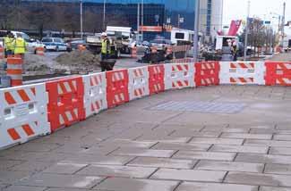
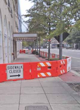
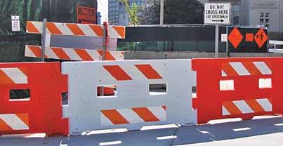
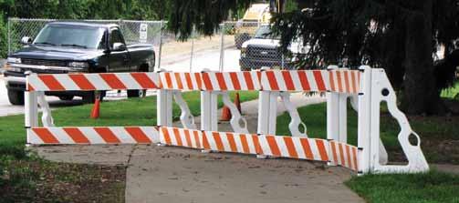
2 SafetyRail ADA-Compliant Pedestrian Barricade For accessible work zones. Use as sidewalk closure barricade or longitudinal channelizer. SafetyWall ADA-Compliant Pedestrian Barricade For accessible work zones. Use as sidewalk closure barricade or longitudinal channelizer. SafetyRail is a continuous, interlocking device, and meets ADA guidelines and MUTCD 2009 Edition Standards as a sidewalk closure barricade or longitudinal channelizer device. Hand-Trailing: Upper rail is smooth, continuous, safer for the hand. Features an oversized sandfill hole for added ballast. Made from high density polyethylene plastic with UVstabilizers. SafetyWall provides the same level of pedestrian guidance as concrete or plastic barrier, but is easier to transport, install and remove. Common vertical plane eliminates obstacles. Gap between bottom of unit and ground is less than 2. No obstacles in the walkway. Cane-Ready: Ground-hugging lower rail reduces potential for trapped cane tips. Designed for use with Wave Guide Rail. See page 4 for more information. Retroreflective sheeting meets all state and federal specifications, and is available in Engineer, Hi-Intensity and Diamond grades. SafetyWall is a continuous, interlocking device, and meets ADA guidelines and MUTCD 2009 Edition Standards as a sidewalk closure barricade or longitudinal channelizer. Cane-Ready: Bottom reduces potential for trapped cane tips. Common vertical plane eliminates obstacles. Gap between bottom guide rail and ground is less than 2. Hand-Trailing: Top is smooth, continuous, safer for the hand. Snap-in installation. No tools required. FHWA Acceptance Letter WZ-278 US Patents Nos. 8,302,937; 7,536,973. Download PSS ADA Pedestrian Barricade Product Guide. No obstacles in the walkway. SafetyWall is an interlocking device. Assembles quickly. No tools required. 1-2 person crew can easily create an accessible work zone in minutes. SafetyWall measures 74 long, 36 tall, 3 thick, and weighs only 35 lbs. SafetyWall stacks for easy storage and transport. Retroreflective sheeting meets all state and federal specifications, and is available in Engineer, Hi-Intensity and Diamond grades. Made from high density polyethylene plastic with UV-stabilizers. FHWA Acceptance Letter WZ-315 US Patent No. D665,689. We use 3M Reflective Sheeting. Page 2 Page 3, Inc Inc Page 3

 Device 3.25 W x 38 H. 24 L at base Round top for smooth transition to handtrailing guide rail.")
, with UV inhibitors Mount for warning lights and audible")


3 SafetyRail TM Specifications SafetyRail TM Features Product known as: Dimensions: ADA-Compliant Pedestrian Barricade Temporary Traffic Control Device Pedestrian Channelizer Device Longitudinal Channelizing Device Type II Barricade Temporary Pedestrian Access Route (TPAR) Device 3.25 W x 38 H. 24 L at base Round top for smooth transition to handtrailing guide rail. Measures 38 from ground. Meets MUTCD standards. Weight: Material: 7 lbs. empty. Fill with up to 25 lbs. of sand High-density polyethylene plastic (HDPE), with UV inhibitors Mount for warning lights and audible warning devices Crashworthy Status: NCHRP-350, Test Level FHWA Acceptance Letters: Used With: SafetyRail Upright: WZ-278 Wave Panel: WZ-173 Wave Guide Rail 0.8 W x 7.5 H x 48 or 72 L High-density polyethylene plastic (HDPE), with UV inhibitors Lugs for easy stacking. Over-size fill hole for internal sand ballast. Wave Guide Rail Wave Guide Rail retroreflective sheeting meets all state and federal specifications, and is available in Engineer, Hi-Intensity and Diamond Grades. Available in unsheeted, or sheeted on one or both sides, in left, right or bi-directional configurations. AVAILABLE in 4 or 6 foot lengths. Top & Bottom guide rail bushings hold rails in place. No installation tools required! Support for optional sand bags. Ergonomic handle for easy transport. Lug for easy stacking Measures 1.5 from ground. Meets MUTCD standards. Temporary Pedestrian Access Route Sidewalk Closure Relief to clear terrain The Notch design keeps guide rails in place. Encapsulated ends eliminate cane or hand snagging hazards. Non-symmetrical design helps pedestrians determine correct access route. Page 4, Inc Inc Page 5


, with UV inhibitors Shown: SafetyWall, left, with SafetyRail")


4 SafetyWall TM Specifications SafetyWall TM Features For accessible work zones. Use as sidewalk closure barricade or longitudinal channelizer. Interlocks to provide continuous, safe, obstacle-free guidance Helps support pedestrians in the event of a fall Product known as: Dimensions: Weight: Material: ADA-Compliant Pedestrian Barricade Temporary Traffic Control Device Pedestrian Channelizer Device Longitudinal Channelizing Device Type II Barricade Temporary Pedestrian Access Route (TPAR) Device 3 W x H 74 L 35 lbs. High-density polyethylene plastic (HDPE), with UV inhibitors Shown: SafetyWall, left, with SafetyRail Transition. For more information, see page 11. Crashworthy Status: MASH, Test Level 3 FHWA Acceptance Letters: WZ-315 Wave Panel: WZ-173 & 244 Retroreflective sheeting meets all state and federal specifications, and is available in Engineer, Hi-Intensity and Diamond grades. Sections stack for easy transport and storage. Watch our SafetyWall Video. US Patent No. D665,689. Legs fold in for easy storage. Accepts Audible Information Devices and Warning Lights. See page 11 for more information. Page 6, Inc Inc Page 7


5 SafetyRail TM Assembly Instructions Attach Guide Rails to the First Upright: Use the LIST method: Line-up - Insert - Secure - Turn No hand tools required. SafetyRail TM Assembly Instructions Attach the 2nd Upright: Line-up the upright with the guide rails. Insert and center the guide rail, beginning with the lower guide rail. Make the guide rail flush with the back of the upright. Secure the guide rail with the bushing. Use the side of the bushing closer to the upright already attached. Turn the UPRIGHT to the desired position. Before you begin: Always assemble SafetyRail onsite. Do not attempt to drag an assembled array to another location. For a successful assembly: Always attach the lower guide rail first! Line-up the guide rail with the upright Insert the guide rail into the center of the bushing. The inserted end of the guide rail must rest flush against the back of the upright. 1 2 Attach more Guide Rails and Uprights: Line-up the guide rails with the 2nd upright, beginning with the lower guide rail. Insert and center the guide rail in the bushing. Make the guide rail flush with the back of the upright. Secure the guide rail with the bushing, in the same direction in which the barricade array will be built. Turn the guide rail to the desired position, and then attach another upright. Ballast Options Warning Device Options Secure the upper and lower notches of the guide rail with the bushing. Use the side of the bushing that is closer to the direction in which the barricade array will be built. Turn the guide rail into a position perpendicular to the upright. The guide rail should turn easily, without force. If the guide rail binds, do not force it to turn. At this point, the SafetyRail Barricade should look just like this. For instructions to attach the second upright, see over. SafetyRail will accommodate Type A or C warning lights. Simply, reverse the process: disengage the guide rail, and start again. Use sandbags, or fill SafetyRail with up to 25 lbs. of sand. SafetyRail will also accommodate some audible warning devices, as shown in the picture on the right. PSS does not manufacture or market warning devices. Page 8, Inc Inc Page 9


 6. Repeat the process for the top 4 Wave panel.")


6 SafetyWall TM Assembly Instructions 1 No fasteners or hand tools required for assembly! Always assemble SafetyWall on-site. Do not attempt to drag an assembled array to another location. Transport SafetyWall to the Installation Site: SafetyWall weighs only 35 lbs. A 1 or 2 person crew can easily transport a single barricade by hand. SafetyWall features fork portals for fork lift transportation. 2 Unfold the legs of the 1st Device: Place the 1st device at the beginning of the channelizer array, with its front facing the pedestrian walkway. Remember, the legs are on the back of the device. Unsnap the legs, and swing them 90 from the unit, or as much as space allows Ballast with sandbags: SafetyWall can function without ballast. For best performance, place at least 1 each 25 lb. sandbag on each leg. SafetyWall TM Assembly Instructions Attach SafetyRail, our other ADA-Compliant Pedestrian Barricade, to SafetyWall! When attaching SafetyRail, the side of the wedge opposite its holes should always face the center of SafetyWall. Attaching SafetyRail to SafetyWall Requires PSS Transition Wedge Kit and hand tools. Front: SafetyWall on left, SafetyRail on right. Back: SafetyRail on left, SafetyWall on right. Use only 4 SafetyRail Wave panels. 1. Facing the front of the SafetyWall device, locate the upper and lower panel mounting holes on either side. Note they are partially molded through. Drill through mounting holes with a 5/16 diameter drill bit. Drill through from both sides. 2. Align the holes of the Transition Wedge with the bottom holes in SafetyWall. 3. Hold the wedge in place on the front side of SafetyWall. Align the 4 Wave panel with both the wedge and SafetyWall. The flange of the wedge should be in-between. The end of the panel should make full contact with the wedge. 4. Fasten the wedge and the panel to SafetyWall with the hardware provided. Fasten the hardware with the flush-mount nut on the pedestrian walkway side. Tighten finger tight. 5. For support, attach the bottom panel to the SafetyRail upright. (See our SafetyRail Assembly Instructions.) 6. Repeat the process for the top 4 Wave panel. Once both panels are attached to SafetyWall and SafetyRail, fully tighten the hardware with hand tools. 7. Cover the exposed notches of the panels with duct-tape, to reduce potential for snagging. 8. Continue to build a SafetyRail SafetyWall array as needed. Mounting Warning Lights & Audible Devices Requires PSS Light Mount and hand tools. Align the 2nd Device with the 1st: Bring a 2nd device into place. Make sure both devices face in the same direction. Align the male pins of the 2nd device with the female ends of the 1st. Insert the Top Male Pin 1st: Slowly insert the top male pin first, ensuring that the bottom pin is in line with the female end. Complete the connection by inserting the bottom pin. Unfold the legs and add Ballast: Unfold both legs of the 2nd device; angle them in a degree similar to the 1st, or as space allows. Add ballast to both legs. Repeat the process, adding 1 device at a time, until the installation is complete. 1. To mount warning lights or audible information devices, use the PSS Light Mount Kit, which includes flush-mounted hardware. 2. Attach PSS Light Mount using either top or bottom mounting holes. (Top holes for devices, bottom for batteries.) Always attach mounts to the back of SafetyWall, the construction side, so that the mounts do not interfere with hand or cane guidance. 3. Attach the light mount with the hardware provided. Fasten the hardware with the flush-mount nut on the pedestrian walkway side. 4. PSS does not manufacture or market warning lights or audible information devices. Follow light or device manufacturers recommendations for installation, maintenance and removal. 5. Note that the PSS Light Mount requires a 4 ½ tamper-resistant bolt and washer to attach lights or audible information devices. 6. Repeat the process wherever warning lights or audible information devices are required in the SafetyWall array. Construction side Pedestrian side Page 10, Inc Inc Page 11

7 PSS Sales Representatives Dario Alvarez Tim Cox Kenny Kolberg Joe Riehl Jeff Tidaback Steve Walker Tim Cox National & Int l Sales Manager Blue Springs, Missouri Cell: tjcox@plasticsafety.com Dario Alvarez Regional Sales Manager Round Rock, Texas Cell: dealvarez@plasticsafety.com Kenny Kolberg Regional Sales Manager Perry, Ohio Cell: kakolberg@plasticsafety.com Joe Riehl Representative Capitol Barricade, Inc. Sacramento, California Cell: jariehl@aol.com Jeff Tidaback Regional Sales Manager Arlington Hts, Illinois Cell: jatidaback@plasticsafety.com Steve Walker Regional Sales Manager Acworth, Georgia Cell: smwalker@plasticsafety.com Customer & Technical Support, Inc Baldwin Rd. Cleveland OH Contact sales staff online. Copyright /13
SafetyRail. Product & Compliance Guide. ADA-Compliant Pedestrian Barricade
 Product & Compliance Guide ADA-Compliant Pedestrian Barricade SafetyRail SafetyRail is an NCHRP-350 certified, MUTCD and ADA-compliant, temporary traffic control device that provides continuous, obstacle-free
Accommodating Pedestrians in the Work Zone
 Accommodating Pedestrians in the Work Zone Guidance for Section C Plan Preparers Some impacts cannot be avoided and those impacts apply to residents, businesses, motorists, and pedestrians alike. However,
ADA on Construction. Guidance for Section C Plan Preparers
 ADA on Construction Guidance for Section C Plan Preparers Some impacts cannot be avoided and those impacts apply to residents, businesses, motorists, and pedestrians alike. However, good planning can minimize
SERIES 2 RAMP OWNER S MANUAL TOOLS REQUIRED: BEFORE YOU BEGIN... Read and understand these instructions before beginning a ramp setup.
 SERIES 2 RAMP OWNER S MANUAL BEFORE YOU BEGIN... Read and understand these instructions before beginning a ramp setup. Use caution and care for your back when lifting, pushing, pulling, folding or unfolding
TRAFFIC CONTROL DEVICES
 TRAFFIC CONTROL DEVICES SIGNS Temporary traffic control work zone signs include regulatory, warning and guide signs utilized to provide regulations, warnings and guidance information to road users impacted
Proposed Language as approved by the NCUTCD on June 23, 2011, for new section on Pedestrian Channelizing Devices
 1 2 3 4 5 6 7 8 9 10 11 12 13 14 15 16 17 18 19 20 21 22 23 24 25 26 27 28 29 30 31 32 33 34 35 36 37 38 39 Proposed Language as approved by the NCUTCD on June 23, 2011, for new section on Pedestrian Channelizing
NOT TO SCALE PUBLIC WORKS STANDARD DETAILS CURB DETAILS DATE: MARCH 2013 FILE NAME: CURB.DWG
 NOT TO SCALE PUBLIC WORKS STANDARD DETAILS CURB DETAILS DATE: MARCH 2013 FILE NAME: CURB.DWG NOT TO SCALE PUBLIC WORKS STANDARD DETAILS SIDEWALK RAMPS DATE: MARCH 2013 FILE NAME: SIDEWALK RAMPS.DWG NOT
A-FRAME RESIN IN & OUT FLIP UP LADDER
 A-FRAME RESIN IN & OUT FLIP UP LADDER NE1222 NOTE FOR SAFETY PURPOSES ALL LADDERS SHOULD BE SECURED BY ATTACHING THEM TO THE TOP LEDGE OF THE POOL. (See step 13 for details) In order for the ladder to
PROWAG/ADAAG Standards Guidance For Temporary Pedestrian Access Route (TPAR) Facilities and Devices
 Facilities and Devices") INTRODUCTION: PROWAG/ADAAG Standards Guidance For Temporary Pedestrian Access Route (TPAR) Facilities and Devices Minnesota Department of Transportation DRAFT Document DRAFT This document was developed
INTRODUCTION: PROWAG/ADAAG Standards Guidance For Temporary Pedestrian Access Route (TPAR) Facilities and Devices Minnesota Department of Transportation DRAFT Document DRAFT This document was developed
INSTRUCTIONS 360 Y-DROP HAGIE STS 2015
 INSTRUCTIONS 60 Y-DROP HAGIE STS 05 INSTRUCTIONS 60 Y-DROP HAGIE STS 05 INTRODUCTION Before beginning, it s important to know where each mounting bracket fits relative to the row spacing involved. The
Model 400ML Audible Information Device
 909 Grace St. Elgin, IL 60120 (847) 931-2455 Model 400ML Audible Information Device Congratulations you have just purchased an A.D.A. Audible Motion Detected Pedestrian Information Devise for the visually
Blocks must always run perpendicular (at 90 degrees) to the fence to ensure adequate stability.
 to the fence to ensure adequate stability.") This information paper is to provide minimum guidelines and information of the erection of temporary fencing for the purpose of barricading, delineation of a work area, and for protection of workers from
This information paper is to provide minimum guidelines and information of the erection of temporary fencing for the purpose of barricading, delineation of a work area, and for protection of workers from
Designing Pedestrian Facilities for Accessibility. Module 8 Maintenance of Pedestrian Facilities and Alternate Pedestrian Access Routes in Work Zones
 Designing Pedestrian Facilities for Accessibility Module 8 Maintenance of Pedestrian Facilities and Alternate Pedestrian Access Routes in s Maintenance of Accessible Features Title II (28 CFR 35.133(a))
3190A NEO-ANGLE DOOR INSTALLATION INSTRUCTIONS. Series MODEL NO
 NEO-ANGLE DOOR INSTALLATION INSTRUCTIONS Series 30A Please read these instructions carefully to familiarize yourself with the required tools, materials, and installation sequences. The Exploded Diagram
Side-of-Pole Mount for 1 Module (SPM1) For Module Types A & B
 For Module Types A & B") Side-of-Pole Mount for 1 Module (SPM1) For Module Types A & B ASSEMBLY INSTRUCTIONS step-by-step assembly and installation Version 1, Rev A PCN 080311-2 SP3363-1 Side-of-Pole Mount for 1 Module (SPM1)
Side-of-Pole Mount for 1 Module (SPM1) For Module Types A & B ASSEMBLY INSTRUCTIONS step-by-step assembly and installation Version 1, Rev A PCN 080311-2 SP3363-1 Side-of-Pole Mount for 1 Module (SPM1)
Bike Rack and Tire Carrier
 Bike Rack and Tire Carrier OWNER'S MANUAL Rev: 10.26.2017 Page 1 Bike Rack and Tire Carrier Owners Manual TABLE OF CONTENTS System 2 Description 2 Prior To Operation 3 Manual Slide-Out Bike Rack Operation
NICROS-GRANITPANELS INSTALLATION MANUAL
 NICROS-GRANITPANELS INSTALLATION MANUAL NICROS, INC. 845 PHALEN BLVD. ST. PAUL, MN 55106 PHONE: 651.778.1975 FAX: 651.778.8080 THANK YOU FOR YOUR PURCHASE OF THIS NICROS PRODUCT Nicros-GranitPanels are
NEW FEDERAL RULES BREAKAWAY SIGN SUPPORTS ARE REQUIRED
 NEW FEDERAL RULES BREAKAWAY SIGN SUPPORTS ARE REQUIRED The Manual on Uniform Traffic Control Devices (MUTCD), which is the national standard used for all roads open to public travel, states that roadside
HoldUp Plus2. Safety Kit included: See additional instructions for installation. REAR WHEEL TRAY. BASE (1x) lock WASHER (1x) KEY (2x) SAFETY CLIP (1x)
 lock WASHER (1x) KEY (2x) SAFETY CLIP (1x)") HoldUp Plus2 InsTAll This product on 2" hitch version of the HoldUp Front WHEEL TRAY assembly (1x) REAR WHEEL TRAY assembly (1x) wrench (1x) BASE (1x) bolt (8X) Lock WASHER (8X) Washer (8x) KEY (2x) SAFETY
HoldUp Plus2 InsTAll This product on 2" hitch version of the HoldUp Front WHEEL TRAY assembly (1x) REAR WHEEL TRAY assembly (1x) wrench (1x) BASE (1x) bolt (8X) Lock WASHER (8X) Washer (8x) KEY (2x) SAFETY
RBI Solar One-Piece Ground Mount Solution GM-GS
 Solar Mounting System Installation Guide RBI Solar One-Piece Ground Mount Solution GM-GS Ballasted Ground Mount System RBI Solar 1292 Logan Circle NW Atlanta, GA 30318 513-618-7240 info@rbisolar.com OVERVIEW
 www.myrower.com support@myrower.com ASSEMBLY Congratulations on purchasing the MyRower! Please see the following pages for instructions on assembling your MyRower. Bits bag contents: Rail Cross Bolt (90mm)
MANUAL OF TEMPORARY TRAFFIC CONTROL ON CITY STREETS
 MANUAL OF TEMPORARY TRAFFIC CONTROL ON CITY STREETS PUBLIC WORKS DEPARTMENT 2015 REVISION 1-2016 REVISION SUMMARY - MARCH 2016 Introduction 1.05 - Specifications for Traffic Control Devices Temporary Traffic
the square steel tube posts, municipalities can use either the U-channel or square steel tube post signs on locally owned roads.
 Wood vs. steel post Foundation design. The key factor of the breakaway design occurs at the foundation of the post installation. For a wood post foundation, a hole is dug in the ground, and a steel sleeve
MODEL #7100X A-FRAME LADDER
 SAVE THESE INSTRUCTIONS DEALER/INSTALLER: GIVE TO HOMEOWNER MODEL #7100X A-FRAME LADDER LADDER MUST BE ATTACHED TO POOL FRAME... DO NOT USE WITH INFLATABLE POOLS ASSEMBLY AND INSTALLATION MANUAL The Anti-Entrapment
SASK-A-POLE OWNERS AND USERS MANUAL
 SASK-A-POLE OWNERS AND USERS MANUAL GENERAL INFORMATION The Saskatchewan Abilities Council s Sask-a-Pole accessibility and transfer aid is designed to help provide safe and easy access to chairs, beds,
Utility Anchor System
 Utility Anchor System The Dayton Superior Utility Anchor System is designed to economically simplify the lifting and handling of precast concrete elements. Its economics, ease of use and versatility will
Konza District Pinewood Derby Track Parts And Assembly Instructions
 Konza District Pinewood Derby Track Parts And Assembly Instructions - 1 - Pinewood Derby Track Parts List: Box 1 of 3 2 each - Race Track Flat Sections 1 each - Race Track Finish Line Section 1 each -
Supplementary Operation, Assembly, Maintenance Manual for F3-42 model and optional attachments
 FERMENATOR TM Supplementary Operation, Assembly, Maintenance Manual for F3-42 model and optional attachments Congratulations on your purchase, and thank you for selecting the Fermenator TM stainless conical
Edison Electric Institute. Work Zone Safety October 4-7, 2009
 Edison Electric Institute Work Zone Safety October 4-7, 2009 1 Your Presenter Mike Kelly Fire Department Battalion Chief (Retired 7/05) Member NCUTCD (Chapter 6) Director/Owner of START Group Consultant
Tripod Setup Guide (M-TPx)
") Items needed: 1/2 inch wrench, mast level (M-MLA), medium size wire cutters, crescent wrench, all-purpose grease, tape measure, tie wraps, redi-mix cement (optional), shovel (optional), sledge hammer (for
Items needed: 1/2 inch wrench, mast level (M-MLA), medium size wire cutters, crescent wrench, all-purpose grease, tape measure, tie wraps, redi-mix cement (optional), shovel (optional), sledge hammer (for
features and benefits:
 Hopup A variety of sizes, kits and options of Hopup displays are available. Hopup tension fabric displays are simple, versatile and can be set up in seconds. Hopups feature a lightweight, durable frame
PROCEDURE FOR ACCOMMODATING PEDESTRIANS IN WORK ZONES FOR CONSTRUCTION AND MAINTENANCE
 PROCEDURE FOR ACCOMMODATING PEDESTRIANS IN WORK ZONES FOR CONSTRUCTION AND MAINTENANCE A.1 STANDARD Measures shall be taken to accommodate pedestrian traffic through and/or around Work Zones for Construction
INSTALLATION, OPERATION AND MAINTENANCE GUIDE
 INSTALLATION, OPERATION AND Placement in Pipeline System When installing Process Development & Control s ElastoTITE Elastomer-Hinged Check Valves in a pipeline, a minimum of five pipe diameters should
FIRST TEAM SPORTS, INC Storm Portable Series Assembly Instructions
 FIRST TEAM SPORTS, INC Storm Portable Series Assembly Instructions WARNING! WARNING! WARNING! THIS BASKETBALL SYSTEM IS SPRING LOADED AND SHIPPED UNDER TENSION. ATTEMPTING TO ASSEMBLE OR DISASSEMBLE ANY
SETTING THE HANDLE HEIGHT ON THE ROLLATOR
 Model No: Maximum User Weight: 10910C (Lightweight) 10928C (Heavy duty) 125kg (20st) (Lightweight) 170kg (27st) (Heavy duty) Height of handles: 780-915mm (30.5-36 ) (Lightweight) 790-930mm (31-36.5 ) (Heavy
Page 1 of 1 04/19/13 SBR
 Office of Roadway Engineering - Plan Insert Sheets Number Title Date Number Title Date Number Title Date 201015 Extension of Anchor Bolts 07/20/12 207000 Bikeway Pavement Marking Details 01/18/13 202010
Work Zone Safety A Look At Best Practices. AASHTO SCOTE June 6, 2016
 Work Zone Safety A Look At Best Practices AASHTO SCOTE June 6, 2016 1 Work Zone Safety Innovations 2 Positive Protection Measures Pedestrian Accommodations Temporary Bicycle Facilities Work Area Lighting
Virginia Department of Transporta on Work Zone Pedestrian and Bicycle Guidance
 Virginia Department of Transporta on Work Zone Pedestrian and Bicycle Guidance May 1, 2016 Table of Contents Page Preface...ii 1. Introduction...1 ADA Requirements...1 Special Pedestrian Populations...2
KERSPLASH POOL CLIMBING WALL INSTALLATION INSTRUCTIONS
 TOLL FREE: 1-800-476-7366 VOICE 651-665-9131 FAX 651-665-9130 EMAIL: INFO@POOLCLIMBINGWALLS.COM EVERLAST CLIMBING 1335 MENDOTA HEIGHTS ROAD MENDOTA HEIGHTS, MN 55120 2012 EVERACTIVE BRANDS Congratulations!
Using Your Bike Friday : Folding Rear Rack
 Using Your Bike Friday : Folding Rear Rack Green Gear Cycling, Inc. 3364 W. 11th Ave. Eugene, OR 97402 800-777-0258 USA & Canada +1-541-687-0487 Int l +1-541-687-0403 Fax www.bikefriday.com info@bikefriday.com
Trogear Bowsprit Through Hull Installation Manual
 Trogear Marine Products, LLC www.trogear.com info@trogear.com 866-616-2978 Trogear Bowsprit Through Hull Installation Manual Congratulations on your purchase of the Trogear Bowsprit which can be installed
RADIUS ROD BUSHING SET
 RADIUS ROD BUSHING SET These are designed to allow your front suspension to operate much more freely than the factory units, with less maintenaance. STICKSION could be a key word here. The front end will
Standards vs. Guidelines. Public Right-of Way Accessibility Guidelines (PROWAG)
") www.access-board.gov Public Right-of Way Accessibility Guidelines (PROWAG) Juliet Shoultz, P.E Transportation Systems Engineer US Access Board Standards vs. Guidelines Guidelines are developed by the Access
www.access-board.gov Public Right-of Way Accessibility Guidelines (PROWAG) Juliet Shoultz, P.E Transportation Systems Engineer US Access Board Standards vs. Guidelines Guidelines are developed by the Access
Trampoline & Enclosure Assembly Instructions
 Trampoline & Enclosure Assembly Instructions Safe user weight 250 lbs (115 kg) Version 718602 The information in this document is subject to change without notice. Copyright Springfree Trampoline Inc.
U.S. Patent No. 7,922,246. Patents Pending
 U.S. Patent No. 7,922,246 Patents Pending 2 Table of Contents Page General Information... 3 Warnings and Cautions... 4 Tools... 6 SmartDock Parts... 6 Initial Set-Up and Adjustment... 7 Select Valve Retaining
Temporary Traffic Control for Highway Work Zones
 Temporary Traffic Control for Highway Work Zones MONTHLY DELMARVA MISS UTILITY MEMBER MEETING MARCH 20, 2014 PRESENTED BY: Adam Weiser, P.E. PTOE Safety Programs Manager Delaware Department of Transportation
SAMPLE PAGE. Section 2... Wire Rope
 Section 2...................................................... Wire Rope Never use any kind of clip to directly connect two straight lengths of wire rope to form a continuous piece. Do not make up slings
Rudder Kit Assembly Instructions for Quest 13
 Rudder Kit Assembly Instructions for Quest 13 Revised 4/2/2015 78501 Rudder System The Hobie Quest is designed for the addition of an optional rudder system. Rudder systems in boats like this allow you
Exceeding Your Expectations Through Superior Workmanship and Design
 Quality Since 1974 Exceeding Your Expectations Through Superior Workmanship and Design Popular Dock Formations Some layouts shown with optional corner section. L Formations I Formations Slip Formations
Kirra Entertainment Unit Assembly Instructions
 irra ntertainment Unit Thank you for your purchase. lease follow the instructions below for correct assembly. dowel x x 0 wedge x C bolt x locking nut x x F G slide x rail long x N wheel slide rail H I
INSTRUCTIONS. for installing ALDON Two-Way LOCOMOTIVE Hinged Derail on wooden ties. For 4-Axle and 6-Axle Locomotives and all Freight Cars
 INSTRUCTIONS for installing ALDON Two-Way LOCOMOTIVE Hinged Derail on wooden ties For 4-Axle and 6-Axle Locomotives and all Freight Cars Manual Lift Sign Holder 4014-18-5-D size 5 4014-18-6-D size 6 4014-18-7-D
MUELLER. A Wall Type. Indicator Post. Reliable Connections. General Information 2. Technical Data/ Dimensions 3. Installation 4-5.
 Installation Instructions manual MUELLER table of contents PAGE A-20814 Wall Type General Information 2 Technical Data/ Dimensions Installation 4-5 Maintenance 6 Parts 7 Indicator Post! WARNING: 1. Read
L-23 Super Blanik Rigging (assembly/disassembly) Guide Maj Carl Kerns
 Guide Maj Carl Kerns") L-23 Super Blanik Rigging (assembly/disassembly) Guide Maj Carl Kerns The L-23 Blanik is a difficult Sailplane to rig (assemble). The wings are heavy and are secured via a single
L-23 Super Blanik Rigging (assembly/disassembly) Guide Maj Carl Kerns The L-23 Blanik is a difficult Sailplane to rig (assemble). The wings are heavy and are secured via a single
MUELLER. A A Adjustable. Vertical Indicator Posts. Reliable Connections. General Information 2. Technical Data 3.
 Installation Instructions manual MUELLER table of contents PAGE A-20806 A-20807 Adjustable General Information 2 Technical Data 3 Dimensions 4 Installation 5-6 Parts 7 Maintenance 8 Vertical Indicator
SCOUT DECK ANCHOR 3 1/4" BONDING SCREW
 SCOUT DECK ANCHOR 16" 16" 1" X 4" ANCHOR BOLT (4) 10" 3 1/8" 5" 6" MIN COPPER WIRE TO ATTACH TO BONDING GRID 3 1/4" BONDING SCREW CONCRETE DECK SPECIFICATIONS: THE AQUA CREEK PRODUCTS' SCOUT DECK ANCHOR
2012 K9100 COMPACT Worldwide Cycling Solutions Through Creative Innovations.
 Home Instruction Sheet Step-1Please check for any missing parts. Model K9100 COMPACT (Basic AirCaddy) aircaddy web page 20 04/03/12 98% (1) T3230-00 METAL WHEEL TRUCK Model K8350 (Aircraft Kit) (Optional)
Marine 6-Boat Free-Standing Racks SKU: Updated November 2011
 Marine 6-Boat Free-Standing Racks SKU: 30-061 Updated November 011 Contains: Marine -Boat Free-Standing Racks (SKU 1-003) Marine 3 rd Boat Expansion Racks (SKU 1-0303) Marine Back Legs (SKU -001) 3 Sets
INSTALLATION INSTRUCTIONS FOR ROLLOVER PROTECTION SYSTEM (ROPS)
") INSTALLATION INSTRUCTIONS FOR ROLLOVER PROTECTION SYSTEM (ROPS) This manual contains assembly, operating, maintenance and safety instructions for your ROPS. Before Installing the ROPS or operating a machine
INSTALLATION INSTRUCTIONS FOR ROLLOVER PROTECTION SYSTEM (ROPS) This manual contains assembly, operating, maintenance and safety instructions for your ROPS. Before Installing the ROPS or operating a machine
TruckSkin System Installation Manual
 TruckSkin System Installation Manual TruckSkin 877-866-SKIN www.truckskin.com How to Install a TruckSkin Page 1...Questions? Call us at 877-866-7546 TruckSkin.com 1 2 Open your package and verify that
COMPLETE STREETS DURING CONSTRUCTION
 COMPLETE STREETS DURING CONSTRUCTION MAINTAINING ACCESSIBILITY FOR ALL Presented by Robbie Burgess, P.E., PTOE Associate Principal Construction Services Manager Howard Stein Hudson rburgess@hshassoc.com
BALL STOP INSTALLTION GUIDE
 BALL STOP INSTALLTION GUIDE GROUND SLEEVE INSTALLATION: 1. Locate the exact location of the ground sleeve. NOTE: Maximum recommended pole spacing is 20 feet on center. 2. Excavate the pole footing; refer
Boat Boat Loader Fitting Instructions
 Aerodynamic & Heavy Duty Roof Rack Systems Australian Made - Australian Owned www.rhinorack.com Boat Boat Loader Fitting Instructions CONTROLLED Balance point 3 Front eye nuts position 3 Transom eye nut
Pedestrian Accommodation in Work Zones:
 Pedestrian Accommodation in Work Zones: A Field Guide February 2018 Work Zone Safety Consortium This material is based upon work supported by the Federal Highway Administration Grant Agreement DTFH61-13-H-00025
AGM 33 PIKE ALL FIBERGLASS. Specifications Length: 92 Diameter 5.5 Weight: 24 lbs Motor Mount: 75mm Fins: 6-3/16 G10 CP: 68 from nose tip Parts List
 ALL FIBERGLASS AGM 33 PIKE Specifications Length: 92 Diameter 5.5 Weight: 24 lbs Motor Mount: 75mm Fins: 6-3/16 G10 CP: 68 from nose tip Parts List (1) Filament Wound Nose Cone w/ Metal Tip (1) Nose Cone
ADA Training Accessible Pedestrian Signal (APS) 2018 MnDOT
 2018 MnDOT") ADA Training Accessible Pedestrian Signal (APS) 2018 MnDOT APS and ADA APS is not currently an ADA Standard and is provided at the discretion of the Title II entity APS is recognized in the MnMUTCD, but
ADA Training Accessible Pedestrian Signal (APS) 2018 MnDOT APS and ADA APS is not currently an ADA Standard and is provided at the discretion of the Title II entity APS is recognized in the MnMUTCD, but
MUELLER A A Non-Adjustable. Vertical Indicator Posts. Reliable Connections. General Information 2. Technical Data 3.
 Installation Instructions manual MUELLER table of contents PAGE A-20808 General Information 2 Technical Data 3 Dimensions 4 A-20809 Non-Adjustable Installation 5-6 Parts 7 Maintenance 8 Vertical Indicator
8MAY15 US RACK, Inc Falcon Drive, Madera, CA
 8MAY15 US RACK, Inc. - 2850 Falcon Drive, Madera, CA 93637-559-661-3050 INSTRUCTIONS for Bedrail-mounted MOTORCYCLE RACK, Model 2001-4TRA WARNING: Do NOT attempt to install or use this rack without following
STATIONARY TRUCK INTERNAL HALYARD V-CLEAT FLAGPOLES FOR QUICK AND PROFESSIONAL INSTALLATION READ ALL INSTRUCTIONS BEFORE PROCEEDING
 9390 South 300 West, Sandy, Utah 84070 801-562-0123 800-782-0500 ColonialFlag.com STATIONARY TRUCK INTERNAL HALYARD V-CLEAT FLAGPOLES FOR QUICK AND PROFESSIONAL INSTALLATION READ ALL INSTRUCTIONS BEFORE
 WALKING / K-WALKER 149K Strovolou Avenue, Strovolos, Nicosia, 2048, Cyprus T: +357 22250115, F: +357 22250116, M: +357 70008830 www.abletools.com.cy info@abletools.com.cy B SERIES KAYE POSTURE CONTROL
Row Marker OEM /
 IMPORTANT: Your new row marker is designed to attach to the Troy-Bilt Hiller-Furrower attachment. If you don t have Hiller- Furrower, call us or visit www.troybilt.com to place an order: OEM-290-250 for
600 / 600FC OWNER'S MANUAL
 PROGRESSION 600 / 600FC OWNER'S MANUAL Issue 2 / Version E - Dec. 10, 1997 Copyright 1997 GAMMA Sports - All Rights Reserved PROGRESSION 600 / 600FC OWNER'S MANUAL TABLE OF CONTENTS PAGE 1... WARRANTY
Assembly Instructions. -Cantilever Boat Lifts
 Assembly Instructions -Cantilever Boat Lifts Winch Instruction Page Safety Information 1. The winch is built for the multipurpose of hauling and lifting operations. It is not to be used as a hoist for
Precision Liquid Settlement Array Manual
 Precision Liquid Settlement Array Manual All efforts have been made to ensure the accuracy and completeness of the information contained in this document. RST Instruments Ltd reserves the right to change
GEMLUX FISHING SYSTEM INSTALLATION AND USER GUIDE
 GEMLUX FISHING SYSTEM INSTALLATION AND USER GUIDE SEPTEMBER 2016 TABLE OF CONTENTS WELCOME TO THE GEMLUX FISHING SYSTEM 3 FIRST THINGS FIRST! 4 WHAT S IN THE BOX? 4 UNPACKAGING 4 WHAT ELSE DO I NEED FOR
L.Ph. Bolander & Sons 1355 Evans Ave. 800/
 L.Ph. Bolander & Sons 1355 Evans Ave. 800/434-5611 San Francisco, Ca. 94124 Fax 415/648-0402 GOUNDSET ALUMINUM FLAGPOLE INSTALLATION INSTRUCTIONS STEP 1: DIG THE HOLE TO THE DIMENSIONS LISTED BELOW STEP
CIRRUS AIRPLANE MAINTENANCE MANUAL
 RUDDER 1. GENERAL The rudder provides airplane directional (yaw) control and includes a rudder trim tab used for yaw trim adjustment. The rudder is of conventional design with skin, spar and ribs manufactured
OWNER'S MANUAL. Copyright 1999 ATS - All Rights Reserved
 OWNER'S MANUAL AL Issue 2 - August 19, 1999 Copyright 1999 ATS - All Rights Reserved OWNER'S MANUAL TABLE OF CONTENTS PAGE 1... WARRANTY PAGE 2... ASSEMBLY INSTRUCTIONS PAGE 4... MOUNTING THE RACQUET PAGE
ORNAMENTAL CANTILEVER GATE INSTRUCTIONS
 U.S.A. Patent Number 5,36,83 ORNAMENTAL CANTILEVER GATE INSTRUCTIONS *NOTICE: Ornamental Cantilever Gates are supplied with rolls of 2 mesh safety screening in sufficient quantities to cover the entire
CHAPTER 5 REWIND STARTERS
 GENERAL INFORMATION CHAPTER 5 REWIND S Rewind starters used on vertical shaft Tecumseh engines are top mount horizontal pull style or side mount vertical pull style. Horizontal shaft engines use side mounted
ADA* for Roadway Design
 ADA* for Roadway Design Incorporating PROWAG** * Americans with Disabilities Act ** Public Rights of Way Accessibility Guidelines Title II of the ADA requirements for pedestrian facilities within public
ARRICADES PLASTX TM BARRICADES PLASTX TM BARRICADES PLASTX TM BARRICADES PLA
 STX TM BARRICADES PLASTX TM BARRICADES PLASTX TM BARRICADES PLASTX TM BARRICA LASTX TM BARRICADES PLASTX TM BARRICADES PLASTX TM BARRICADES PLASTX TM BARRI STX TM BARRICADES PLASTX TM BARRICADES PLASTX
WELL COMPLETION & PROTECTION. www. .com MINERAL EXPLORATION ENVIRONMENTAL GEOTECHNICAL GEOTHERMAL ROTARY SONIC HDD
 WELL COMPLETION & PROTECTION MINERAL EXPLORATION ENVIRONMENTAL GEOTECHNICAL GEOTHERMAL ROTARY SONIC HDD www..com WELL COMPLETION & PROTECTION TABLE OF CONTENTS TABLE OF CONTENTS (FLUSHMOUNTS)... 2-5 MONITORING
ADA & Public Rights of Way
 ADA & Public Rights of Way Overview of Current and Up-coming Requirements FDOT Design Training Expo 2012 Orlando, FL Dean Perkins, RA - ADA Coordinator Florida Department of Transportation Office of Design,
ITE 2013 Annual Meeting Session 36. Utah Statewide Pedestrian Treatment Guidance Manual Standards for At-Grade Crossings F-ST99(180)
") ITE 2013 Annual Meeting Session 36 Utah Statewide Pedestrian Treatment Guidance Manual Standards for At-Grade Crossings 10661 F-ST99(180) John G. Van Hoff, P.E. Travis Bailey, E.I.T. John.vanhoff@aecom.com
ITE 2013 Annual Meeting Session 36 Utah Statewide Pedestrian Treatment Guidance Manual Standards for At-Grade Crossings 10661 F-ST99(180) John G. Van Hoff, P.E. Travis Bailey, E.I.T. John.vanhoff@aecom.com
Gurney Flap for WRX and STI w/low Profile Trunk Spoiler
 Gurney Flap for 2015+ WRX and STI w/low Profile Trunk Spoiler 2017-12-05 Thank you for purchasing this PERRIN product for your car! Installation of this product should only be performed by persons experienced
Standard Hangers and Adapters
 Standard s and Adapters Cable Gripping Tabs Prevent cable slippage without the need for a permanently installed hoisting grip. Pre-Assembled and Captivated Hardware Eliminates the need for field assembly.
Model: 5100 OmniSteel Volleyball System
 Model: 5100 OmniSteel Volleyball System Installation, Operation and Maintenance Instructions Please read all instructions before attempting installation or operation of these units SAVE THESE INSTRUCTIONS
Design Overview. Section 4 Standard Plans for Design. Pedestrian Access Routes. Pedestrian Access Routes. Overview. Cross Slope
 Design Overview Section 4 Standard Plans for Design Fall, 2017 Ann Johnson, PE Services Brady Rutman, SRF Consulting Group Overview Design Basics Recommendations: The Zone System Driveway Crossings Pedestrian
Spring steel fasteners KWHS-14R. KwikWire. Hanging system
 Spring steel fasteners KWHS-14R KwikWire Hanging system KwikWire Hanging System Takes the strain out of hanging with chain The KwikWire Hanging System is a flexible replacement for jack chain and all thread
Only. Gives You the TechLock. System Advantage ASSEMBLY, DISASSEMBLY AND TROUBLESHOOTING INSTRUCTIONS FOR 3000 SERIES FONTAINE
 April 00 Only Gives You the TechLock System Advantage ASSEMBLY, DISASSEMBLY AND TROUBLESHOOTING INSTRUCTIONS FOR 000 SERIES FONTAINE C o n n e c t y o u r b u s i n e s s w i t h F O N T A I N E April
DE8410 FIVB Official Beach Volleyball Net
 DE8410 FIVB Official Beach Volleyball Net User s Manual For Safety Use Caution Misuse causes unexpected injury and net damages. Keep the net away from solid and sharp materials. Keep the rope away from
Parts List. Description. Additional Considerations. Installation Instructions. Dual/Elite Hydraulic Treadmill Kit (supplied by EPI)
") Page 1 of 9 Parts List Dual/Elite Hydraulic Treadmill Kit (supplied by EPI) Qty Description Treadmill Body 1 Treadmill Power Unit (per Treadmill Body) 2 Treadmill Decks (per Treadmill Body) 1 Treadmill
Page 1 of 9 Parts List Dual/Elite Hydraulic Treadmill Kit (supplied by EPI) Qty Description Treadmill Body 1 Treadmill Power Unit (per Treadmill Body) 2 Treadmill Decks (per Treadmill Body) 1 Treadmill
B-LINE SERIES. Spring steel fasteners KWHS-15. KwikWire. Hanging system
 Spring steel fasteners KWHS-5 B-LINE SERIES KwikWire Hanging system KwikWire hanging system. Takes the strain out of hanging with chain Application Photos Applications for the KwikWire Hanging System include:
SECTION 10iS: TAILCONE
 VAN'S AIRCRAFT, INC. F-1282-R BOTTOM RIGHT SKIN F-1283C J-STIFFENER F-1278 TOP SKIN F-00009-L ADAHRS BRACKET F-00009-R ADAHRS BRACKET F-1279-R UPPER RIGHT SKIN F-1280-R RIGHT SIDE SKIN SECTION 10iS: TAILCONE
REVOCABLE PERMIT FOR STREET BANNER APPLICATION PACKAGE
 Development Engineering 300 Richards Blvd., 3rd Floor Sacramento, CA 95811 Engineering Services Division REVOCABLE PERMIT FOR STREET BANNER APPLICATION PACKAGE Phone: 916-808-8300 Fax: 916-808-1984 Preparation
200 STRINGING MACHINE
 200 STRINGING MACHINE OWNER S MANUAL Issue 1 - July 2010 Provided by www.gssalliance.com 200 OWNER S MANUAL TABLE OF CONTENTS WARRANTY...PAGE 2 FEATURES...PAGE 3 ASSEMBLY INSTRUCTIONS...PAGE 4 MOUNTING
Operator s Manual. All-Terrain Wheelchair
 Operator s Manual All-Terrain Wheelchair By Brandon Calavan Ana Groff Steve Benn Dylan Rinker Sebastian Pineo Team 1 Faculty Advisor: John Enderle Teaching Assistant: Sarah Brittain Client: Melody Kettle
Safety System Installation Guide for ARE Wind Poles
 Safety System Installation Guide for ARE Wind Poles V. 1 May 2011 ** Climbing pegs and ladder should be installed before the pole is erected.** A. Install climbing pegs Install climbing pegs (bolt set)
Installation and Training Manual
 AirForce1 Tower Kit Installation and Training Manual FuturEnergy Limited Ettington Park Business Centre Stratford upon Avon CV37 8BT +44 (0)1789 451070 Table of Contents Safety Notes... 3 Parts Supplied
Apex 3 Theory of Operation
 Apex 3 INSTALLATION & OVERVIEW... 2 Load Height... 2 Approach Angle... 2 Footprint... 3 Protrusion... 3 Mounting the Apex3... 4 General Torque Specs... 5 OPERATION OF BIKE RACK... 6 Loading Bikes... 6