Geometric Design Guidance PREPARED BY TRAFFIC AND SAFETY
|
|
|
- Darrell Cannon
- 5 years ago
- Views:
Transcription

1 Geometric Design Guidance PREPARED BY TRAFFIC AND SAFETY September 2017
2 Engineering Manual Preamble This manual provides guidance to administrative, engineering, and technical staff. Engineering practice requires that professionals use a combination of technical skills and judgment in decision making. Engineering judgment is necessary to allow decisions to account for unique site-specific conditions and considerations to provide high quality products, within budget, and to protect the public health, safety, and welfare. This manual provides the general operational guidelines; however, it is understood that adaptation, adjustments, and deviations are sometimes necessary. Innovation is a key foundational element to advance the state of engineering practice and develop more effective and efficient engineering solutions and materials. As such, it is essential that our engineering manuals provide a vehicle to promote, pilot, or implement technologies or practices that provide efficiencies and quality products, while maintaining the safety, health, and welfare of the public. It is expected when making significant or impactful deviations from the technical information from these guidance materials, that reasonable consultations with experts, technical committees, and/or policy setting bodies occur prior to actions within the timeframes allowed. It is also expected that these consultations will eliminate any potential conflicts of interest, perceived or otherwise. MDOT Leadership is committed to a culture of innovation to optimize engineering solutions. The National Society of Professional Engineers Code of Ethics for Engineering is founded on six fundamental canons. Those canons are provided below. Engineers, in the fulfillment of their professional duties, shall: 1. Hold paramount the safety, health, and welfare of the public. 2. Perform Services only in areas of their competence. 3. Issue public statement only in an objective and truthful manner. 4. Act for each employer or client as faithful agents or trustees. 5. Avoid deceptive acts. 6. Conduct themselves honorably, reasonably, ethically and lawfully so as to enhance the honor, reputation, and usefulness of the profession.
3 INTRODUCTION TO GEOMETRIC DESIGN The following are intended to provide guidance relating to a variety of traffic safety and operational issues and/or needs. This includes geometric design guidance, traffic volume warranting criteria, and direction regarding the submission and review of various analyses and reports. Many of these sections include hyperlinks and/or references to other source material which provide additional details regarding the subject of interest. Included among these other reference sources are the Michigan Department of Transportation (MDOT) Geometric Design Guides and the Michigan Road Design Manual. The use of such other reference sources in conjunction with this guidance is strongly encouraged, as they typically provide a much greater level of detail than that which is found in the various sections. Most the geometric guidance is divided into two broad categories: Operational Considerations and Safety Considerations. Within these two categories, the sections are further sub-divided into Intersection Treatments and Corridor/Midblock Treatments. There are a few sections categorized as Miscellaneous Considerations. These did not fit neatly into either of the first two categories. The Miscellaneous Considerations are further sub-divided into sections relating to Parking, Studies and Analyses, and Lighting. The intent of this categorization is to allow the reader of this guidance to quickly reference the appropriate treatments and/or countermeasures to a variety of traffic issues, be they operations related or safety related. It should be noted that there is a great deal of overlap within the sections. This was done intentionally, because traffic operations and traffic safety are intrinsically linked to each other. Many of the treatments that can be considered primarily as operational improvements also have the effect of improving traffic safety. Conversely, many of the treatments considered primarily as safety improvements also have the effect of improving traffic operations. Therefore, many of the sections appear in both categories.
4 This page is intentionally blank.
5 Geometric Design Table of Contents 1.0 Operational Considerations 1.1 Intersection Treatments Required Intersection Widening to Accommodate New Traffic Signals Divided Roadway Intersections Clear Vision Areas Traffic Volume Guidelines for Right-Turn Lanes and Tapers Traffic Volume Guidelines for Left-Turn Lanes and Passing Flares Near Side/Far Side Lane Drops Roundabouts 1.2 Corridor Treatments Roadside Traffic Control Islands Spacing for Commercial Drives and Streets Traffic Volume Guidelines for Driveway Passing Flares Traffic Impact Studies Traffic Impact Assessments Truck Route Classification Considerations 2.0 Safety Considerations 2.1 Intersection Treatments Traffic Volume Guidelines for Right-Turn Lanes and Tapers Traffic Volume Guidelines for Left-Turn Lanes and Passing Flares Clear Vision Areas Roundabouts 2.2 Corridor Treatments Roadside Traffic Control Islands Traffic Volume Guidelines for Driveway Passing Flares On-Street Angled Parking 3.0 Miscellaneous Considerations 3.1 Parking On-Street Angled Parking Parking Facility Dimensions 3.2 Studies and Analyses Design Exception/Variance Truck Route Classification Considerations Traffic Impact Studies Traffic Impact Assessments 3.3 Lighting Non-Freeway Lighting Freeway Lighting Illumination at Railroad Crossings
6 This page is intentionally blank.
7 1.0 OPERATIONAL CONSIDERATIONS The following are related primarily to traffic operational issues. The sections are divided into two types of treatments: Intersection Treatments and Corridor/Midblock Treatments. It should be noted that while this guidance typically pertains to traffic operational issues, many of these treatments provide tangible traffic safety benefits as well as operational improvements. 1.0 Operational Considerations 1.1 Intersection Treatments Required Intersection Widening to Accommodate New Traffic Signals Divided Roadway Intersections Clear Vision Areas Traffic Volume Guidelines for Right-Turn Lanes and Tapers Traffic Volume Guidelines for Left-Turn Lanes and Passing Flares Near Side/Far Side Lane Drops Roundabouts 1.2 Corridor/Midblock Treatments Roadside Traffic Control Islands Spacing for Commercial Drives and Streets Traffic Volume Guidelines for Driveway Passing Flares Traffic Impact Studies Traffic Impact Assessments Truck Route Classification Considerations
8 1.1.1 Required Intersection Widening to Accommodate New Signals When a Stop-and-Go traffic signal is installed at an intersection, the capacity of the through roadway is reduced by about half. In addition, left turning traffic can interlock, effectively stopping all through traffic. As a result, prior to the installation of a Stop-and- Go traffic signal, all legs of the intersection should have a minimum of two approach lanes. Additional widening may be required to provide for capacity. An alternative to widening would be to prohibit left turns or provide for one way streets. If widening is required, it shall be done in accordance with MDOT Geometric Design Guide GEO-650. The crossroad shall provide a minimum of two approach lanes also. The crossroad widening shall be the responsibility of, and financed by, the roadway authority. At locations with a single approach lane, intersection widening will typically be required in order to obtain two approach lanes as required to accommodate a new traffic signal.
9 1.1.2 Divided Roadway Intersections The Legal definition of an intersection at/of a divided roadway is dependent on the dividing distance. The Michigan Vehicle Code (P.A. 300, 1949, as amended) Section provides that where a highway includes two roadways 30 feet or more apart, then every crossing of each roadway of such divided highway by an intersecting highway shall be regarded as a separate intersection. In the event such intersecting highway also includes two roadways 30 feet or more apart, then every crossing of two roadways of such highways shall be regarded as a separate intersection (emphasis added). This legal definition of an intersection depends on the distance between the traveled portions (defined as roadway in the Vehicle code) of the highway and becomes important in some cases of traffic control. For example, the regulatory sign COMPLETE LEFT TURN WHEN TRAFFIC CLEARS is limited to applications where the median width is less than 30 feet (one intersection). Interpretation of Section defining intersections indicates that the median width should be considered as: 1. The distance from through traveled way pavement edge to through traveled way pavement edge for uncurbed medians (please refer to the associated sketch on next page. 2. The distance from curb face to curb face for curbed medians. Part 2 of the Michigan Manual on Uniform Traffic Control Devices (MMUTCD) provides direction for use and placement of traffic control devices at divided highway intersections, conforming to the 30 foot (9 m) definition. An Attorney General opinion has clarified some questions as to exactly what constitutes a median. According to this: 1. If each roadway is uncurbed, the width of the median should be measured from the edge of the through traveled way pavement to the through traveled way pavement. Hence, shoulders should be considered as part of the median measurement (please refer to the associated sketch on next page). 2. If each roadway is curbed, the width of the median should be measured from curb face to curb face. 3. If a paved left-turn bay is provided, the turn bay should be considered as part of the roadway improved for vehicular travel, and the width of the median should be measured from the edge of the turn bay (or adjacent curb face). 4. If two left-turn bays were provided at the same intersection, both bays should be considered as the roadway improved for vehicular travel and the measurements made accordingly. For additional information and geometric design guidance regarding divided roadway intersections, medians, and median crossovers, please refer to MDOT Geometric Design Guide GEO-670.
10 Example of Median Width Measurement on an Uncurbed Divided Roadway
11 1.1.3 Clear Vision Areas In order to enhance the safe and efficient movement of traffic, the acquisition of certain properties (or portions thereof) at intersections sometimes is necessary. The following guidelines should be followed. Clear vision areas will be obtained at all at-grade intersections of trunklines with other roads or streets in rural areas including freeway ramps. Interchange ramps are considered trunkline. Clear vision areas will not be obtained within urban areas as determined by the Bureau of Transportation Planning's urban area boundary description and map. Clear vision areas will not be obtained within rural areas contiguous to sections of trunkline where urban conditions exist to the extent that 50 percent or more of the trunkline frontage is occupied by residential, business, or industrial development. The Region/TSC Traffic and Safety Representative reviews each case from a traffic operational and safety standpoint and recommends one of the following courses of action: acquire all or part of area, defer acquisition in particular quadrant to future date, or eliminate all clear vision. For additional information and guidance regarding clear vison areas, please refer to MDOT Geometric Design Guide GEO-300 and the Michigan Road Design Manual, Chapter 5. Right Of Way.
12 1.1.4 Traffic Volume Guidelines for Right-Turn Lanes and Tapers The addition of right-turn lanes or tapers at intersections should be considered to enhance the traffic movements and improve traffic operations and safety. Exclusive right-turn lanes should be considered. The following traffic volume guidelines have been established and are outlined below. Guidelines for Right-Turn Lanes and Tapers The use of right-turn lanes or tapers should be considered in the following conditions: 1. At any intersection where a capacity analysis determines a right-turn lane or taper is necessary to meet a desired level of service. 2. At any intersection where the crash experience, existing traffic operations or engineering judgment indicates that a right-turn lane or taper will significantly improve operations. 3. At any unsignalized intersection which satisfies the criteria in the following two charts. The following two charts on the next page (from the NCHRP Report #279, Intersection Channelization Design Guide) show the relationship between peak hour approach volumes and peak hour right-turns. When the intersection peak hour approach volume and peak hour right-turns fall below the lower trend line, radius improvements may be required. If the intersection falls between the two trend lines, taper improvements are recommended. If the intersection falls above the upper trend line, a full-width right-turn lane is recommended. For additional information and geometric design guidance regarding right-turn lanes and tapers, please refer to MDOT Geometric Design Guide GEO-650.
13 NOTE: For posted speeds at or under 45 mph, peak hour right turns greater than 40 vph, and total peak hour approach less than 300 vph, adjust right turn volumes. Adjust peak hour Right turns = Peak hour Right turns 20 *If a center left-turn lane exists (ie 3 or 5 lane roadway), subtract the number of left turns in approach volume form the total approach volume to get an adjusted total approach volume. Sample Problem: The Design Speed is 55 mph. The Peak Hour Approach Volume is 300 vph. The Number of Right Turns in the Peak Hous is 100 vph. Determine if a right turn lane is recommended. Solution: Figure indicates that the intersection of 300 vph and 100 vph is located above the upper trend line; thus, a right-turn lane may be recommended.
14 Example of Median Width Measurement on an Uncurbed Divided Roadway
15 1.1.5 Traffic Volume Guidelines for Left-Turn Lanes and Passing Flares at Unsignalized Intersections The addition of left-turn lanes or passing flares should be considered in order to enhance the traffic operations and safety at intersections. MDOT has established guidelines for the consideration of these intersection treatments, as provided in the following charts. The first three charts display the relationship between advancing and opposing volumes with respect to left-turns on two-lane, two-way highways. For each of the three charts, if the intersection of advancing and opposing volumes falls to the right of the curve representing the percentage of left-turns in the advancing volume, a left-turn lane is recommended. If the intersection falls to the left of the curve, a left-turn lane is not recommended. If a left-turn lane is not recommended, consider the installation of a passing flare. For additional information and geometric design guidance regarding left-turn lanes and passing flares, please refer to MDOT Geometric Design Guide GEO-650. The fourth chart displays the relationship between the left-turning volumes and opposing volumes on four-lane, undivided highways. A left-turn lane is generally not warranted if the intersection of left-turning volumes and opposing volumes falls within the shaded area. These charts are taken from NCHRP Report 279, Intersection Design Guide. Guidelines for Left-Turn Lanes on Two-Lane, Two-Way Highways and Four-Lane, Undivided Highways The accommodation of left turns is often the critical factor in proper intersection design. Left-turn lanes and passing flares can significantly improve safety and the level of service at an intersection. Exclusive left-turn lanes should be considered under the following conditions: 1. At any unsignalized intersection on a two-lane urban or rural highway which satisfies the criteria in the first three charts. 2. At any unsignalized intersections on a four-lane urban or rural highway which satisfies the criteria in the fourth chart. 3. At any intersection where the crash experience, traffic operations, sight distance restrictions (e.g., intersection beyond a crest vertical curve), or engineering judgment indicates that a left-turn lane will significantly improve operations. If a left-turn lane is not recommended, a passing flare should be considered. Passing flares are discussed in Section and Section of this document.
16 Instructions: 1. The family of curves represent the percentage of left turns in advancing volume (V A). The designer should locate the curve for the actual percentage of left turns. When this is not an even increment of 5, the designer should estimate where the curve lies. 2. Read V A and V O into the chart and locate the intersection of the two volumes. 3. Note the location of the point in #2 relative to the line in #1. If the point is to the right of the line, then a left-turn lane is recommended. If the point is to the left of the line, then a left-turn is not recommended based on traffic volumes. Example: Speed = 35mph Advancing volume during DHV = 400 vph Opposing volume during DHV = 400 vph Percentage of left-turns in advancing volume = 7% Problem: Solution: Determine if left-turn lane is recommended Figure indicates that the intersection of 400 vph and 400 vph is located to the left of the 7% curve (estimated); thus a left-turn lane is not recommended based on volumes.
17 Instructions: 1. The family of curves represent the percentage of left turns in advancing volume (V A). The designer should locate the curve for the actual percentage of left turns. When this is not an even increment of 5, the designer should estimate where the curve lies. 2. Read V A and V O into the chart and locate the intersection of the two volumes. 3. Note the location of the point in #2 relative to the line in #1. If the point is to the right of the line, then a left-turn lane is recommended. If the point is to the left of the line, then a left-turn is not recommended based on traffic volumes.
18 TWO-LANE HIGHWAYS WITH A POSTED SPEED OF 55 MPH OR GREATER Instructions: 1. The family of curves represent the percentage of left turns in advancing volume (V A ). The designer should locate the curve for the actual percentage of left turns. When this is not an even increment of 5, the designer should estimate where the curve lies. 2. Read V A and V O into the chart and locate the intersection of the two volumes. 3. Note the location of the point in #2 relative to the line in #1. If the point is to the right of the line, then a left-turn lane is recommended. If the point is to the left of the line, then a left-turn is not recommended based on traffic volumes.
19 NOTE: When V O <400 vph (dashed line), a Left-Turn Lane is Not Normally Warranted Unless The Advancing Volume (V A ) in The Same Direction as the Left-Turning Traffic Exceeds 400 vph (V A > 400 vph).
20 1.1.6 Near Side/Far Side Lane Drops The following guidelines, based on an ITE report, are qualitative in order to encourage the evaluation of lane drops at intersections on an individual basis: General 1. Engineering judgment is the primary basis for determining the appropriate intersection lane drop, near-side or far-side. Additionally, engineering judgment should prevail when applying the distances recommended in these guidelines to specific traffic conditions. 2. Intersection capacity, intersection turning volumes (especially right turns), parking and right of way restrictions, design speed, lighting, and safety are significant considerations in the evaluation of the appropriate intersection lane drop, either near-side or far-side. 3. The Decision Sight Distance concept is applicable to the geometric design and placement of traffic control devices for both near-side and far-side intersection lane drops. 4. Intersection lane drops present the driver with a high judgment, complex driving situation and, therefore, the most effective signing and pavement marking is recommended (please refer to the appropriate figures). 5. Far-side intersection lane drops are preferred over near-side. To some extent both types of lane drops have been used for different purposes (far-side for capacity; near-side for operations). 6. Intersection lane drops can be associated with an interim condition before a highway widening is extended at a future date. If it is planned to continue the widening, a far-side lane drop has the advantage of placing the beginning of the new construction well beyond the intersection (please refer to the appropriate figures). Near-Side Intersection Lane Drop 1. A near-side intersection lane drop is applicable at an urban area intersection with a heavy right turn volume and is not recommended for use in a high speed, unlighted rural area. The trap lane should be avoided except where extenuating circumstances such as a heavy right turn volume and/or where a far-side intersection lane drop is not feasible due to constraints (e.g. prohibitive right of way costs). 2. The Decision Sight Distance concept can be applied to the placement of traffic control devices for near-side intersection lane drops. The distances traveled during the reaction time (detection, recognition, decision, response) plus the vehicle maneuver time will produce the total Decision Sight Distance values required for various posted speeds (please refer to Table 1). These Decision Sight Distance values, in addition to allowances for queue lengths (assumed signalized intersection), will establish reasonable sign and pavement marking locations (please refer to the top figure).
21 3. The signing and pavement markings for near-side intersection lane drops need special emphasis. An advance warning sign, THRU TRAFFIC MERGE LEFT (W4-7), is recommended. Advance street name signs and special pavement markings in the dropped lane will also reinforce the advance warning sign and provide motorists with the necessary guidance to react and maneuver the vehicle safely and effectively to avoid the trap lane (please refer to the top figure). In addition, lane control signs (R3-7 series) or RIGHT LANE MUST TURN RIGHT (R3-7R) support the use of the right turn lane. The same sign should be used at both locations. Far-Side Intersection Lane Drop 1. A far-side intersection lane drop is applicable to both an urban and rural areas, and is considered to be the preferred intersection lane drop treatment (please refer to the bottom figure). 2. At unsignalized intersections, Decision Sight Distance can be utilized to determine the length beyond the intersection at which the lane should be dropped using the values indicated in Table At signalized intersections, a two part analysis is required. Adequate vehicle storage beyond the intersection, brought about by the release of vehicles from the traffic signal, must be considered in addition to the Decision Sight Distance requirement. The larger of the values calculated using these analyses will provide the required length beyond the intersection as measured from the stop bar. 4. Proper taper lengths (L) are calculated from the following formulas: L = W x S, for S greater than or equal to 45 mph, or, L = WS 2 /60, for S less than 45 mph (where W = width in feet and S = speed in mph). 5. Effective signing and pavement markings are necessary components to ensure a successful lane drop operation. The signing and pavement markings shown in the bottom sketch are recommended for far-side intersection lane drops.
22 Advance placement distance (d): See Traffic Sign Design Placement, and Application Guidelines (TSDPAG) Table 3: Condition A. See PAVE Standards for pavement marking details.
23 Decision Sight Distance Table 1
24 1.1.7 Roundabouts Roundabouts are a circular form of intersection design increasingly being utilized in the United States, including by the Michigan Department of Transportation. Roundabouts differ from more conventional intersection types in their geometry, traffic control, and traffic operations. When appropriately sited, roundabouts can provide better operational efficiencies and greater safety benefits than traditional intersection designs. Roundabout design is somewhat site-specific; there is no one-size-fits-all approach. However, there are certain universal characteristics which define all modern roundabouts. Some of the more significant elements common to properly designed roundabouts include: Counterclockwise Flow All traffic travels in a counterclockwise direction around a central island. Deflected Entries The approaches to the roundabout are deflected, or curved, in the direction of the circulatory roadway; they do not intersect at 90 degree angles. This facilitates a smooth entry into the roundabout. Yield Control on Entries All traffic entering the roundabout must yield right-of-way to traffic already circulating within the roundabout. Low-Speeds The alignment and curvature of the roundabout results in low-speed operations (generally in the mph range) throughout the roundabout. Because of their low operating speeds, acute impact angles, and reduced number of conflict points, roundabouts substantially reduce fatal and severe injury traffic crashes. Per the AASHTO Highway Safety Manual, roundabouts reduce severe injury and fatal crashes by 78 percent to 82 percent as compared to conventional stop-controlled or signalized intersections. Before-and-after studies conducted on Michigan roundabouts identified reductions in injury crashes for all classes of roundabout conversions. The analysis estimated injury crash reductions that range from a low of 20 percent for signalized intersections converted to three-lane roundabouts to a high of 70 percent for signalized intersections converted to one- and two-lane roundabouts. One or two-way stop controlled intersections converted to roundabouts displayed a 40 percent reduction in injury crashes while all-way stop controlled intersections converted to a roundabout had a 36 percent reduction. While researchers identified an overall increase in crashes for most types of roundabout conversions, the reduction in injury crashes provides a net crash cost benefit for most conversion types. Researchers calculated a return on investment of less than two years for all three types of roundabouts, attributing this relatively quick return to the significant reduction in crashes and the benefits associated with reductions in user delay. Furthermore, roundabouts are designed to improve safety for all road users, including pedestrians and bicyclists. For these reasons, the FHWA Office of Safety has identified roundabouts as a Proven Safety Countermeasure.
25 As stated previously, roundabout design is site-dependent. Proper design often requires the incorporation of some design flexibility and allowances, tempered by engineering judgment and sound design principles. For this reason, it is beyond the scope of this document to provide firm, specific design parameters and values. Instead, reference should be made to NCHRP Report 672 (Roundabouts: An Informational Guide, Second Edition) for detailed information regarding the planning, siting, design, and operation of roundabouts. NCHRP Report 672 is the Michigan Department of Transportation s preferred source for roundabout guidance. The principles, techniques, and design parameters put forth in NCHRP Report 672 regarding the planning and design of roundabouts are consistent with, and supported by, the department.
26 1.2.1 Roadside Traffic Control Islands Roadside traffic control islands should be considered at those locations where it is apparent that their installation will enhance traffic operations and safety. Roadside traffic control islands should be considered in the following situations: 1. The location has a history of traffic crashes correctable by traffic islands. 2. Crash potential exists, as evidenced by disorganized parking along the roadside where vehicles create conflicts as they move in and out of the traffic main stream. 3. Crash potential is evidenced by parked cars blocking vision. 4. Vehicles backing onto the highway or making other erratic maneuvers interfere with the smooth flow of traffic. 5. Vehicular movements to private property within the vicinity of an intersection disrupt traffic. 6. Grade differential between the highway and a roadside business requires roadside control to organize movements into a desired location and/or path. 7 Driveways are undefined or are not in accordance with current guides. The curb type used in the construction of traffic control islands should be in accordance with current MDOT guidelines. Please refer to the Michigan Road Design Manual, Section 6.06 Curb and Gutter for additional information regarding curb and gutter selection. The full shoulder should be paved between the roadway and the island, where applicable.
27 1.2.2 Spacing for Commercial Drives and Streets The spacing of access for commercial driveways and streets is an important element in the planning, design, and operation of roadways. Access points are the main location of crashes and congestion. Their location and spacing directly affect the safety and functional integrity of the roadway. Region Review: The Region/TSC Utility and Permit Engineer shall forward the site plan and the access request to the Region/TSC Traffic and Safety Representative for review. In general, one access point is adequate for a single business. When one-way pair driveways (In-Out) are requested and the inside traffic circulation promotes such operation, these driveways may be considered as a single access point. In some cases multiple access points are requested. In this case, the Region/TSC Traffic and Safety Representative may require a traffic impact study from the business owner/property owner to justify the need for the multiple accesses. A copy of the following information may be sent to the business owner/property owner to outline the traffic analysis needed. Unsignalized Access Spacing: Adjacent accesses should be spaced as far apart as on-site circulation allows. In some cases the Region/TSC Traffic and Safety Representative may require that the business owner/property owner redesign his site plan, and relocate the access point to meet the desirable spacing distance. Table 1 shows the desirable unsignalized access spacing as a function of posted speed. These distances are based on average acceleration and deceleration considered adequate to maintain good traffic operations. The sight distance at the access points must also be investigated. Posted Speed mph (km/hr) Center-to-Center of Access feet (meters) 25 (40) 130 (40) 30 (50) 185 (55) 35 (60) 245 (75) 40 (60) 300 (90) 45 (70) 350 (105) 50 (80) and above 455 (140) Table 1 Lack of Sufficient Frontage to Maintain Adjacent Spacing: In the event that a particular parcel lacks sufficient frontage to maintain adequate spacing, the Region/TSC Traffic and Safety and Utility and Permit Engineers have the following options. 1. Choose the next lowest spacing from Table 1. For example, on 30 mph (50 km/hr) roadway requiring 185 ft (56 m) spacing, the distance may be reduced to no less than 130 ft (40 m) which is the spacing from 25 mph (40 km/hr) speed.
28 2. Encourage a shared driveway with the adjacent owners. In such case the driveway midpoint may be located at the property line between two parcels. However, all parties must agree to the joint driveway in writing. 3. Provide an access point to the side street when it is possible. 4. In areas where frontage roads or service drives exist or can be constructed, individual properties shall be provided access to these drives rather than directly to the main highway. 5. After all the above options are exhausted, an access point may be allowed within the property limits as determined by the Region/TSC Traffic and Safety and the Utility and Permit Engineers. Intersection Corner Clearance: AASHTO specifically states that driveways should not be situated within the functional boundary of at-grade intersections. This boundary includes the longitudinal limits of auxiliary lanes. An access point may be allowed within the above boundary if the entire property frontage is located within this boundary. In all quadrants of an intersection access points should be located according to the dimensions shown in Figure 1. Conflict Reductions: Restricting or prohibiting left turns at unsignalized access points aligned across from each other can greatly reduce safety and operational problems. A typical four-legged intersection, such as where two accesses line up across a four-lane roadway, has 36 conflict points. By prohibiting left turns and through movements the number of conflicts can be reduced from 36 to four, as illustrated in Figure 2. In cases where these movements cannot be prohibited, the Region/TSC Traffic and Safety Representative may choose to offset the access points. Table 2 provides the desirable distances between two access points on the opposite side of the roadway. Desirable Offset Between Access Points on Posted Speed mph (km/hr) Opposite Sides of the Roadway Center-to-Center of Access On Undivided Highways feet (meters) 25 (40) 255 (80) 30 (50) 325 (100) 35 (60) 425 (130) 40 (60) 525 (160) 45 (70) 630 (190) 50 (80) and above 750 (230) Table 2 Passing Flares at Driveways: To evaluate the need for passing flares at driveways on twolane, two-way roadways, refer to the Traffic Volume Guidelines for Driveway Passing Flares section (Section 1.2.3) of this document.
29 Right-turn Lanes or Tapers at Intersection: The addition of right-turn lanes or tapers should be considered to enhance the movement of traffic through intersections. To evaluate the need for right-turn lanes and tapers, refer to the Traffic Volume Guidelines for Right-Turn Lanes and Tapers section (Section 1.1.4) of this document. Left-Turn Lanes or Passing Flares at Intersections: To evaluate the need for left-turn lanes or passing flares at intersections, refer to the Traffic Volume Guidelines for Left-Turn Lanes and Passing Flares at Unsignalized Intersections section (Section 1.1.5) of this document. Access Design: All access points shall be designed to meet the Michigan Department of Transportation guides, standards and Construction Permit Manual. Signalized Intersection Spacing: Traffic signal spacing criteria should apply to all intersecting public streets and access drives. They should take precedence over unsignalized spacing standards where there is a potential for signalization. Ideally, locations of signalized intersections should be identified first. Various studies have shown that the number of traffic signals per mile has an even greater influence on travel speeds than the traffic volume per lane. Therefore, selecting a long and uniform signalized intersection spacing is the first essential element in establishing access spacing guides. The variables involved in the planning, design and operation of signalized roadways are reflected in the relationship between speeds, cycle length and signal spacing which yield maximum bi-directional progression band widths. Thus, a signal timing plan must be able to provide efficient traffic flow with a speed compatible to the roadway posted speed. Table 3 represents the relationship between cycle length, speed and approximate distances between signals for bidirectional progression. The traffic representative may elect to relocate or consolidate drives in order to meet the spacing in Table 3. Spacing criteria can be reduced when only one direction of travel is signalized. Peak Speed mph (km/hr) Hour Cycle 25 (40) 30 (50) 35 (60) 40 (60) 45 (70) 50 (80) 55 (90) or above Length Distance (sec) Feet m feet m feet m feet m feet m feet m Feet m 60 1, , , , , , , , , , , , , , , , , , , , , , , , , , ,300 1,000 3,630 1, , , , ,520 1,070 3,960 1,210 4,400 1,340 4,840 1,475 Table 3 Approximate Distances between Signalized Intersections Needed to Achieve Efficient Bidirectional Progression at Various Speeds and Cycle Lengths
30 Figure 1
31 Figure 2

32 1.2.3 Traffic Volume Guidelines for Driveway Passing Flares Driveways serving large developments along state trunkline highways frequently generate large numbers of left-turns. On two-lane, two-way roadways, this situation can aggravate the efficiency of traffic operations and often make shoulder maintenance difficult. In such situations, prohibition of left-turns at driveways to large developments or construction of driveway passing flares should be considered. In an attempt to alleviate the types of problems outlined above, the following chart is provided showing the relationship between peak hour left-turns and 24-hour volumes. When peak hour leftturns and 24-hour volumes fall within the area above and to the right of the trend line, left-turns should be prohibited or a driveway passing flare be installed. If a driveway passing flare is constructed, the entire cost should be borne by the developer. For additional information and geometric design guidance regarding driveway passing flares, please refer to Geometric Design Guide GEO-650. NOTE: This chart is based on Total Development and is for Two-Way Roadways.
33 1.2.4 Traffic Impact Studies A traffic impact study is a complete analysis and assessment of traffic generated by a proposed development and of the impact a proposed development would have on the surrounding transportation system. A traffic impact study is required for any proposed development expected to generate over one hundred (100) peak hour directional trips or at the discretion of the Region/TSC Traffic and Safety Engineer. The study shall be completed and sealed by a licensed professional engineer. The consulting firm shall be pre-qualified by MDOT to do Traffic Capacity Analysis and Geometric Studies. If the study includes the review of potential signal operations, a pre-qualified Traffic Signal Operations consultant must be used. Lansing Traffic and Safety, as well as the Region, should review these studies. The table at the end of this section gives examples of land uses that are expected to meet or exceed the 100 peak hour directional trip threshold. Region Review: 1. The Region/TSC Utilities and Permits Section reviews all proposed access plans, and then forwards the plans to the Region Traffic and Safety Engineer with their recommendations. Region Traffic and Safety will notify the Utilities and Permits Engineer if a traffic impact study is required from the developer before the access permit can be issued. 2. The Utilities and Permits Engineer will inform the developer of the required impact study. 3. If an access management corridor team has been established in the vicinity of said development, the draft impact study will be submitted to the corridor team for advisory input prior to awarding a MDOT permit. A traffic impact study should include: 1. A disclaimer which indicates that the opinions, findings, and conclusions expressed in this TIA are those of the authors and not necessarily those of the MDOT. 2. A narrative summary at the beginning of the report, including, but not limited to: a. The applicant and project name. b. A location map with dimensions with references to state trunklines. c. The size and type of development. d. Generated traffic volumes based on type and size of land use which are compatible with those listed in the Institute of Transportation Engineers (ITE) publication, Trip Generation (current edition).
34 e. A disclaimer indicating why the TIA is being completed. f. A location for MDOT (Lansing Traffic and Safety and the Region) to indicate they reviewed the TIA and accept/reject the assessment. 3. Project phasing identifying the year of development activities per phase and proposed access plan for each phase. 4. A transportation system inventory, which describes the physical, functional and operational characteristics of the study area highway system and, where pertinent, local transit services. The description should provide, where applicable, data regarding: a. Peak-hour volumes for individual traffic movements (existing and projected) (The growth rates used for traffic volume projections should come from the Urban Travel Demand Model or the Statewide Model. If not, the annual growth rate selected for use shall be subject to approval by MDOT staff). b. Number of lanes c. Cross-section d. Intersection traffic signals and configuration e. Traffic signal progression f. Percentage of heavy trucks g. Adjacent access point locations h. Jurisdiction i. Grades 5. A plan showing proposed roadway per phase for each access. The plan needs to be in scale and show lane configurations, drives, traffic signals, and other geometric information pertinent to the study. Driveway design and roadway improvements shall meet Michigan Department of Transportation standards and guides. 6. A capacity analysis shall be performed at each access point. The Department software preference is Synchro. Default values shall not be used when actual values are reasonably available or obtainable. Every effort should be made to obtain accurate values, or good, justifiable estimates. The interaction of conflicting traffic movements shall be addressed in the traffic impact study. Any proposed signalized access point within 1 mile (1.6 km) of an existing signalized intersection shall be analyzed in coordination with the existing signal timing along the entire signalized corridor. A time-space diagram should also be included. 7. A traffic impact study on the trunkline shall be analyzed with and without the proposed development on the existing system, and with the proposed development for both existing and projected traffic volumes. The growth rates used for traffic volume projections should come from the Urban Travel Demand Model or the Statewide Model. If not, the annual growth rate selected for use shall be subject to approval by MDOT staff).
35 The traffic volumes for the development shall assume a total build out. If desired, the traffic volumes generated by each individual phase may be provided as well. If the development generates 500 or more trips in the peak hour, then a minimum 5-year horizon forecast must be included. This means total traffic (background + development) forecasted at least 5 years beyond opening year. o 500 peak hour trips (In+Out) after reductions for by-pass trips o If development has an opening day and a future buildout, then the future buildout can serve as the 5 year horizon forecast (only if the future buildout is at least 5 years after opening day) If the development is at or near a major intersection or interchange, then traffic generated for the site should also be shown relative to movements into and/or through the intersection or interchange. Large developments should indicate expected market area such as a shopping mall. The completed traffic analysis shall be summarized in a table showing all the Measures of Effectiveness (MOE s) for each individual traffic movement for all the above conditions. 8. Required operational changes and/or other mitigation measures shall be part of the permit approval process. 9. The consultant and the Department should strive to reach an agreement on the assumptions and methodology of the traffic impact study. In areas where an agreement cannot be reached, the Department may provide a response to the traffic impact study that will be made part of the final study and included in the appendix.
36 Land Use Residential: Examples of Land Use Size Thresholds Based on Trip Generation Characteristics 100 Peak Hours Directional Metric Single Family 150 units 150 units Apartments 245 units 245 units Condominiums/Townhouses 295 units 295 units Mobile Home Park 305 units 305 units Shopping Center (GLA) (3) 15,500 sq. ft. 1,440 m 2 Fast Food Restaurant w/drive-in (GFA) 5,200 sq. ft. (4) 480 m 2 Convenience Store w/gas (GFA) (3,5) 1,300 sq. ft. or 5 pumps 120 m 2 or 5 pumps Banks w/drive-in (GFA) 4,400 sq. ft. 410 m 2 Hotel/Motel 250 rooms 250 rooms General Office 55,000 sq. ft. (4) 5,110 m 2 Medical/Dental Office 37,000 sq. ft. 3,440 m 2 Research & Development 85,000 sq. ft. 7,900 m 2 Light Industrial 115,000 sq. ft. 10,680 m 2 Manufacturing 250,000 sq. ft. 23,225 m 2 NOTES: 1. Rates/equations used to calculate the above thresholds are from Trip Generation, 5th Edition, 1991, by the Institute of Transportation Engineers. This table will likely need updating as future editions provided additional information. 2. For example, a full traffic impact study should be completed (100 peak hour, peak direction trips generated) if 150 or more single family units are proposed for a site. 3. GLA Gross Leasable Area; GFA Gross Floor Area. 4. Using AM peak-hour rates/equations would provide a lower threshold. However, adjacent roadway volumes are usually higher during the PM peak hour. 5. Uses both Service Station with Market and Convenience Market with Pumps data. 6. For further trip generation characteristics of the above land uses, or of other uses not illustrated above, refer to the latest version of Trip Generation.
37 1.2.5 Traffic Impact Assessments A traffic impact assessment is completed for uses which generate a relatively low volume of traffic. A traffic impact assessment is required for any proposed development expected to generate between fifty (50) and ninety-nine (99) peak hour directional trips, or at the discretion of the Region/TSC Traffic & Safety Engineer. The table at the end of this section gives examples of land uses that are expected to meet or exceed the fifty (50) peak hour directional trip threshold. A traffic impact study (as outlined in Section 1.2.4) shall be required for any proposed development expected to generate over ninety-nine (99) peak hour directional trips, or if requested by the Region/TSC Traffic & Safety Engineer. Lansing Traffic and Safety, as well as the Region, may review these studies. The Traffic Impact Assessment should include: 1. A narrative summary at the beginning of the report, including, but not limited to: a. The applicant and project name. b. A location map with dimensions including proposed drives and distances and/or references to state trunklines. c. The size and type of development. 2. Generated traffic volumes based on the type and size of land use which are compatible with those listed in the Institute of Transportations Engineers (ITE) publication Trip Generation (current edition). They should be in the area of the proposed site drives. The traffic volumes for the development shall assume a total build out. Both the peak hour trip generation and the daily trip generation should be used. Local or specific development data can be used, if available, only at the discretion of the Region/TSC Traffic Engineer. Developers can use their own data in the collection of estimated traffic generated. The use of secondary data outside of the ITE Trip Generation Manual is acceptable as long as the business that is being referenced is comparable in type and size to the proposed development and the state trunkline and local primary connectors have similar ADT. The ITE Trip Generation Manual has small sample sizes for several types of developments, and may not be the best source of information for data collection purposes. 3. Existing Traffic Volumes Volumes during peak hours adjacent to the site. 4. Project phasing identifying the year of development activities per phase and the proposed access plan for each phase. 5. Trip Distribution/Assignment for the proposed drives. Trip distribution/assignment is for the peak hours (assuming morning and evening). Weekend peak hour data may be requested by the Region/TSC Traffic Engineer if applicable.
38 6. Access: Identify the location of any existing drives within approximately 450 feet (140 m) of the site. Identify the location of the proposed drives. A proposed driveway spacing based on a 50 MPH (80 Km/h) posted speed is suggested, if feasible. Please refer to Section for additional guidance regarding the spacing of commercial driveways. If it is determined that the impacts of the development affect areas beyond the proposed drives, additional information or assessment may be requested. If there are any existing corridor groups studying or managing the area of the proposed development, coordination with these groups will be needed regarding the proposed project. A corridor group can be defined as a transportation planning group consisting of local officials, MDOT staff, and various other key stakeholders interested in preserving and/or improving the safety, capacity, economic sustainability, and aesthetics of a particular transportation corridor. Examples of Land Use Size Thresholds
39 Based on Trip Generation Characteristics (This document is a guideline) 50 Peak Hours Land Use Directional Metric Residential: Single Family 70 units 70 units Apartments 115 units 115 units Condominiums/Townhouses 125 units 125 units Mobile Home Park 140 units 140 units Shopping Center (GLA) 5,200 sq. ft. 480 m2 Fast Food Restaurant w/drive-in (GFA) 2,600 sq. ft. 242 m2 650 sq. ft. or 3 60 m2 or 3 Convenience Store w/gas (GFA) pumps pumps Bank w/drive-in (GLA) 2,200 sq. ft. 205 m2 Hotel/Motel 120 rooms 120 rooms General Office 22,000 sq. ft. 2, 045 m2 Medical/Dental Office 18,600 sq. ft. 1,728 m2 Research & Development 37,000 sq. ft. 3, 440 m2 Light Industrial 58,000 sq. ft. 5,390 m2 Manufacturing 125,000 sq. ft. 11,615 m2 NOTES: 1. For example, a traffic impact assessment should be completed (50 peak hour, peak directional trips generated) if 70 or more single family units are proposed for a site. 2. GLA Gross Leasable Area 3. GFA Gross Floor Area
40 1.2.6 Truck Route Classification Considerations Traffic and Safety has the responsibility of evaluating trunklines for operational, safety, and traffic considerations. The following factors should be considered when evaluating the addition of routes to the Special Designated System (Green Routes) as shown on the current TRUCK OPERATOR S MAP. This map is available online. 1. Safety Record of the Roadway. Crashes should be evaluated and the crash rate of the roadway section should be compared to the region and statewide crash rates. 2. Site Review for Safety Concerns. The sufficiency report should be reviewed for roadway condition and percentage of no passing zones. 3. Alternate Routes. The availability of an alternate route may preclude addition of a proposed roadway section. 4. Existing Cross-sections. The current lane widths should be reviewed to determine if geometric improvements are needed. Generally, paved shoulder ribbons are added to 11 foot (3.3 m) and 12 foot (3.6 m) lanes, while 10 foot (3.0 m) lanes may be precluded from the system. 5. Sight Distance. No Passing Zones should not exceed 40 percent of the section of route being considered for reclassification. If feasible, the level of service should be used as determining criteria. 6. Severity and Lengths of Grade. The addition of climbing lanes may be necessary with the addition of large vehicles. 7. Shoulder widths. Shoulder widths should be as recommended by AASHTO, with the possible inclusion of paved shoulders. 8. Review Bridges. Review bridges underclearances and bridge widths on the proposed truck route. 9. Turning Radii. Review the intersection radii to see if trucks can be accommodated. Intersection widening may be needed to accommodate truck movements.
41 2.0 SAFETY CONSIDERATIONS The following are related primarily to traffic safety issues. The sections are divided into two types of treatments: Intersection Treatments and Corridor/Midblock Treatments. It should be noted that while this guidance typically pertains to traffic safety issues, many of these treatments provide tangible improvements to traffic operations as well as increased traffic safety benefits. 2.0 Safety Considerations 2.1 Intersection Treatments Traffic Volume Guidelines for Right-Turn Lanes and Tapers Traffic Volume Guidelines for Left-Turn Lanes and Passing Flares Clear Vision Areas Roundabouts 2.2 Corridor/Midblock Treatments Roadside Traffic Control Islands Traffic Volume Guidelines for Driveway Passing Flares On-Street Angled Parking
42 2.1.1 Traffic Volume Guidelines for Right-Turn Lanes and Tapers See Section Traffic Volume Guidelines for Left-Turn Lanes and Passing Flares at Unsignalized Intersections See Section Clear Vision Areas See Section Roundabouts See Section Roadside Traffic Control Islands See Section Traffic Volume Guidelines for Driveway Passing Flares See Section
43 2.2.3 On-Street Angled Parking Pull-in angled parking will not be permitted on state trunkline. Only back-in angled parking will be considered. In some downtown areas, a parallel parking configuration does not adequately meet the demand for parking spaces or is limited by other operational issues. In these areas, the use of back-in angled parking can increase parking capacity or more appropriately address site constraints. In order to consider the use of back-in angled parking over parallel parking, the following criteria shall be considered and documented by the local government agency: - A capacity analysis shall be performed, demonstrating that future peak hour traffic conditions under the proposed cross section will operate at an acceptable level of service with the addition of back-in angled parking (e.g. LOS D or better in urban areas and LOS C or better in rural areas). - The vehicle overhang at the curb shall not reduce the pedestrian walkway effective width to less than 5 feet or in any way impede Americans with Disability Act (ADA) accessibility. - Parking spaces shall not exist within Intersection Sight Distance triangles. - All geometric elements of the proposed cross section shall meet department standards. The following additional criteria should be considered: - An adequate clear area should be provided behind the face of curb to allow for vehicle overhang. Fixed object placement and maintenance in this area are critical concerns. - Existing auxiliary lanes (i.e. Turn lanes at intersections) should be preserved. - The proposed cross-section with back-in angled parking should be able to accommodate an existing or planned bike lane as defined in the community s non-motorized plan in support of the department s complete streets policy. The implementation of back-in angled parking requires approval of Michigan Department of Transportation (MDOT) Engineering Operations Committee (EOC). A formal resolution from the city/village/township council or board must be provided to MDOT in support of the request. A template resolution which can be used by city/village/township council or board is at the end of this section. The last paragraph of this template resolution beginning, Now, Therefore be it Resolved,... must be included before MDOT will consider a study for back-in angled parking on the requested route. The city/village/township will be responsible for the study To accommodate back-in angled parking a reduction in the number of through lane on the requested route may be required. The city/village/township will be responsible for this
44 evaluation. If a lane reduction or Road Diet is required to accommodate back-in angled parking then a traffic engineering study must be performed and included in the study for back-in angled parking. The traffic engineering study must be performed by a MDOT pre-qualified Traffic Capacity Analysis & Geometric Studies consultant. MDOT reserves the right to evaluate any trunkline corridor with back-in angled parking that exhibits operational and/or safety concerns to determine if the type of parking is having any impacts detrimental to the corridor. If such concerns are documented, MDOT will take corrective actions that may include the restoration of prior parking configurations.
45 RESOLUTION City/Village/Township of County Council/Board person offered the following Resolution and moved for its adoption. WHEREAS, the current parking configuration on from to does not adequately meet the demand for parking spaces or is limited by other operational issues due to the steady development and growth of city/village/township over the past years, and WHEREAS, implementation of back-in angled parking can increase parking capacity or address site constraints impacting parking along the roadway, NOW, THEREFORE BE IT RESOLVED, city/village/township/council or board is formally requesting the Michigan Department of Transportation (MDOT) to consider a study on, from to for the purposes of determining the potential for angled parking for the purposes of angled parking. It is understood MDOT will use engineering data gathered in the study to make a decision which could change the existing parking to back-in angled parking or maintain the existing parking configuration. It is further understood city/village/township will be responsible for the study and abide by the decision made by MDOT as a result of this study and that MDOT reserves the right to evaluate the roadway if any operational and/or safety concerns are exhibited, to determine if angled parking is having any detrimental impact to the roadway. If such concerns are documented, MDOT will make corrective actions that may include restoration of prior parking configurations.
46 3.0 MISCELLANEOUS CONSIDERATIONS The following provide guidance relating to a variety of miscellaneous traffic issues. The sections are divided into three categories: Parking, Studies and Analyses, and Lighting. 3.0 Miscellaneous Considerations 3.1 Parking On-Street Angled Parking Parking Facility Dimensions 3.2 Studies and Analyses Design Exception Request Crash Analysis Truck Route Classification Considerations Traffic Impact Studies Traffic Impact Assessments 3.3 Lighting Non-Freeway Lighting Freeway Lighting Illumination at Railroad Crossings
47 3.1.1 On-Street Angled Parking See Section
48 3.1.2 Parking Facility Dimensions State-owned parking lots should be wide enough to provide two or more parking bays. Ninety (90) degree parking is generally preferred where two-way traffic operations exist. Forty-five (45) to seventy-five (75) degree angle parking is often used where one-way traffic operations exist. Parking stall widths of 10 feet are commonly used for parking facilities. It is recommended that the widths be measured from the center of the pavement marking to the center of the next pavement marking. A parking stall depth of 18 feet is utilized in most situations. The curb should be set back if any vehicle bumper contact beyond the curb is critical. In general, the curb set-back should be about 2.5 feet for pull-in parking, and 4.0 feet for backin parking. Parking layout for a given site will depend primarily on the following elements: 1. The size and shape of the available area. 2. The type of facility: attended or self-park. 3. The type of parking: long-term versus short-term. 4. The type of operation: pull-in, back-in, one-way, two-way, etc. Please refer to Pavement Marking Standard PAVE-956 for further information and guidance regarding parking area pavement markings and recommended widths for the pavement marking lines. The following exhibit provides the minimum parking layout dimensions for four different angles of parking for state-owned parking facilities.
49
50 3.2.1 Design Exception/Variance A safety review is required for all 3R and 4R projects. The Project Manager should contact the TSC Traffic Engineer during scoping, so that a safety review can be performed throughout the project limits. On corridor projects only one analysis that includes roadways and bridges is required. This review should consist of an analysis of available crash data to determine where safety enhancements are warranted. Safety reviews more than three years old shall be updated to verify the original safety review. A site-specific crash analysis is required as justification for any design exception or design variance. It is also required in determining appropriate 3R design criteria according to Section A and B of the Road Design Manual. Site specific crash analyses more than three years old shall be updated to verify the original crash analysis. During the review process the Geometric Design Unit will review plans and identify the need for Design Exceptions (DE) or Design Variances (DV) when standards are not met for specified geometric design elements. These elements are listed below with their corresponding level of documentation and/or approval. For more information on design exceptions/variances go to Section E of the Road Design Manual. For information on how to complete the crash analysis for a design exception/variance see Chapter 2 of the Safety Programs Manual, Design Exception/Variance Request Crash Analysis. Applicability of Design Exception Non-Standard Design Element (NHS and Non-NHS) (See(DE) Design Variance (DV) Section for DE Criteria for 3R freeway work) Design Speed 50 MPH < 50 MPH Design Speed < Posted Speed DE DE Lane Width* DE DV Shoulder Width DE DV Horizontal Curve Radius* DE DV Superelevation Rate* DE DV Superelevation Transition* DV DV Maximum Grade* DE DV Stopping Sight Distance (Horizontal and Vertical)* DE DV Cross Slope DE DV Vertical Clearance DE DE Design Loading Structural Capacity DE DE Ramp Acceleration / Deceleration Length* DV DV *Values based on design speeds less than posted.
51 3.2.2 Truck Route Classification Considerations See Section Traffic Impact Studies See Section Traffic Impact Assessments See Section
52 3.3.1 Non-Freeway Lighting Local governmental agencies are responsible for the installation, operation, and maintenance of lighting on non-freeway state trunklines. When a local agency requests a permit from the Region Utilities-Permits Engineer to install or upgrade lighting on a trunkline, the Region/TSC Representative should review the plans for such work to ensure that light standards and utility poles are located so as to provide a safe recovery area for motorists. Matters relating to illumination levels may be referred to the Municipal Utilities Design Unit in the Design Division. Please refer to the Michigan Road Design Manual, Chapter 9 for additional guidance regarding the placement of lighting standards and utility poles and in the latest edition of the AASHTO Roadway Lighting Design Guide.
53 3.3.2 Freeway Lighting Freeway lighting facilities may be provided under the following conditions: 1. If a proposed project meets the warrants for either continuous freeway lighting, interchange lighting on unlighted freeways, or lighting for freeway bridges, overpasses and underpasses, as discussed in the AASHTO Roadway Lighting Design Guide, the project shall be reviewed by the department to determine the extent of lighting to be furnished. For interchange lighting refer to the Interchange Lighting Guidance Document (10235). 2. Freeway lighting will be provided only if it enhances highway safety as determined by the Region/TSC analysis. The design of the system shall be such that it contributes to the overall safety of the freeway. 3. Continuous freeway lighting and full interchange lighting should be designed in accordance with the AASHTO publication noted above. 4. Isolated interchange lighting shall be designed for a maintained average illumination of 1.0 foot candles (10.75 lux) maximum. 5. Partial interchange lighting may be considered for any interchange. 6. Freeway lighting standards shall not be used in urban freeway medians unless they are installed on the top of the concrete median barriers. Ordinarily, lighting standards are located on the perimeter of the roadway. 7. The Electrical Design Unit in Lansing Design will review all designs of freeway lighting facilities and coordinate with other involved support areas. Freeway lighting exceeding that which the department has approved for traffic safety purposes may be furnished and maintained at the expense of the local governmental agency. Such lighting must be in accordance with department specifications and approved by permit. Please refer to the Michigan Road Design Manual, Chapter 9 for additional guidance regarding the placement of lighting standards and utility poles and in the latest edition of the AASHTO Roadway Lighting Design Guide.
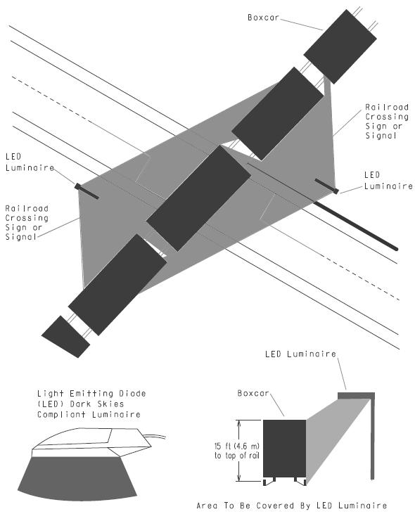
54 3.3.3 Illumination at Railroad Crossings This guideline was developed to assist in the placement of lighting at railroad at-grade crossings. In general, the lighting should illuminate passive and/or active warning devices, the pavement surface and markings, and the presence or absence of a train in or approaching the crossing. The luminaries should be aligned toward the railroad tracks instead of the roadway. The figure on page 2 shows a recommended lighting configuration. General Guidelines - The first three guidelines are being adopted from an article entitled Seven Years into Illumination at Railroad-Highway Crossings by Richard A. Mather, Crossing Signal Specialist for the Oregon Public Utility Commission. At least one luminaire shall be mounted on each side of the track at the crossing. Luminaires should be located so that warning devices at the crossing will be directly illuminated. Luminaires shall be oriented toward the railroad track to provide at least 1 ft candle (11 lux) of illumination on the vertical plane 5 ft (1.5 m) from the centerline of track. (Maximum permissible level of illumination and exact orientation of the luminaire will be determined on a case-by-case basis. Factors at the site, including the ambient level of nighttime illumination, need to be considered.) [Note: The maximum level of illumination is related to the level of lighting on the roadway approaches. The level of illumination should be sufficient to alert drivers to the crossing ahead and to any railroad equipment occupying the crossing, but should not be so bright as to create a blinding effect for motorists in the area immediately beyond the crossing. Cutoffs will normally be used on luminaries to minimize this blinding effect.] Luminaries should illuminate an area along the track which is 50 percent wider than the traveled width of the road. For example, if the road is 20 ft (6.1 m) in width, the roadway width plus 5 ft (1.5 m) along the track on each side of the road should be illuminated. If the roadway is less than 20 ft (6.1 m) in width, a minimum illumination of 5 ft (1.5 m) down the track should be maintained. The illumination should cover a distance which is equal to the normal height of rail equipment [at least 15 ft (4.6 m) above the top of the rail]. Section 9.03 of the department s Road Design Manual discusses the placement of light standards. Poles should be placed a minimum of 9.0 ft (2.7 m) from the center line of the track to maintain track clearance requirements.
55 Pole placement should be checked to insure that the pole provides minimal obstruction of the motorists view down the track. In addition, pole placement shall be such that it does not obstruct the train crews distant view down the track and so that the luminaire is not confused with any wayside train signals. Full cutoff luminaries are recommended where wayside train signals are used. Poles holding luminaries should be located so they can be maintained from the highway right-of-way. Suggested Design from Seven Years into Illumination at Railroad-Highway Crossings Single Track Crossings Poles should be located approximately 25 ft (7.6 m) from both the road and the centerline of the railroad track. 8,850 ftlbs/min (250 watt) Light Emitting Diode (LED) Dark Skies Compliant luminaries should be placed at least 30 ft (9.1 m) above the top of the rail, on arms which are 6 ft to 16 ft (1.8 m to 4.9 m) long. If a railroad signal system is involved, full cutoff luminaries are recommended. Multiple Track Crossings 17,700 ft-lbs/min (400 watt) LED Dark Skies Compliant luminaries should be placed at least 40 ft (12.2 m) above the top of the rail. If there is a considerable distance between the tracks, it may be desirable to install a luminaire between the tracks. Semi-cutoff luminaries are recommended because they spread the light over a larger area of the crossing. This treatment is needed particularly at crossings of three or more tracks and/or crossings having severe angles of intersection. MDOT Design Coordination The department s Electrical Design Unit in Lansing has suggested the following be considered when placing lighting at railroad crossings: If the utility company completes the installation, the design may be completed by the company to meet the general guidelines above. For trunkline projects, the Electrical Design Unit may review the plans. Certain designs may require additional specifications and plan sheets. On trunkline projects, these will be provided on an individual basis by the Electrical Design Unit. Details of Lighting Structure The Electrical Design Unit has suggested the following be considered when placing lighting at railroad crossings. Requirements 1. Section A2 of RAILROAD CROSSINGS should be followed
56 2. 11,063 ft-lbs/min (250 watt) LED Dark Skies Compliant luminaire ft (10.7 m) mounting height 4. Photocell on lights Considerations 1. Source of payment for the energy needs to be worked out between the local government and the utility company/railroad/road Authority. 2. If the utility company does the installation, all they need are the basics and they will finish the design. The Electrical Design Unit can check their plans. 3. Certain designs may require additional specifications and plan sheets provided on an individual basis by the Electrical Design Unit. Installation The cost of installation may be paid for by the Governmental and Railroad Coordination Section of Lansing Design. Costs for future electricity may be paid for by Region/TSC maintenance. Cost details should be worked out before the lighting is installed. Maintenance According to Mather, in 1990, the average monthly maintenance cost per luminaire/pole was $15. This includes electricity and maintenance activities. This cost was for lights that the road authority took ownership of after installation. Public owned utilities were slightly less. Source of payment for the energy should be arranged between the involved parties. REFERENCES: Mather, Richard A., Crossing Signal Specialist for the Oregon Public Utility Commission, Seven Years into Illumination at Railroad-Highway Crossings, June Michigan Department of Transportation, Road Design Manual, Section Roadway Lighting RP-8, American National Standard, IES (Illuminating Engineering Society).
57
TRAFFIC AND SAFETY NOTE 608A. Spacing for Commercial Drives and Streets. To Promote a Uniform Practice in Determining Access Spacing
 TRAFFIC AND SAFETY NOTE 608A SUBJECT: PURPOSE: Spacing for Commercial Drives and Streets To Promote a Uniform Practice in Determining Access Spacing COORDINATING UNIT: Geometric Design Unit INFORMATION:
Roundabout Design Aid PREPARED BY TRAFFIC AND SAFETY
 Roundabout Design Aid PREPARED BY TRAFFIC AND SAFETY May 2018 Engineering Manual Preamble This manual provides guidance to administrative, engineering, and technical staff. Engineering practice requires
Guidance for Installation of Pedestrian Crosswalks on Michigan State Trunkline Highways
 Guidance for Installation of Pedestrian Crosswalks on Michigan State Trunkline Highways Michigan Department of Transportation July 7, 2014 Engineering Manual Preamble This manual provides guidance to administrative,
Recommended Roadway Plan Section 2 - Land Development and Roadway Access
 Recommended Roadway Plan Section 2 - Land Development and Roadway Access SECTION 2 Land Development and Roadway Access 2.1 Land Use and Access Management The Federal Highway Administration (FHWA) defines
Access Location, Spacing, Turn Lanes, and Medians
 Design Manual Chapter 5 - Roadway Design 5L - Access Management 5L-3 Access Location, Spacing, Turn Lanes, and Medians This section addresses access location, spacing, turn lane and median needs, including
TRAFFIC STUDY GUIDELINES Clarksville Street Department
 TRAFFIC STUDY GUIDELINES Clarksville Street Department 9/1/2009 Introduction Traffic studies are used to help the city determine potential impacts to the operation of the surrounding roadway network. Two
MUTCD Part 6G: Type of Temporary Traffic Control Zone Activities
 MUTCD Part 6G: Type of Temporary Traffic Control Zone Activities 6G.01 Typical Applications Each temporary traffic control (TTC) zone is different. Many variables, such as location of work, highway type,
4.0 TRAFFIC IMPACT STUDIES
 SECTION 4 4.0 TRAFFIC IMPACT STUDIES 4.1 TRAFFIC IMPACT STUDY REQUIREMENTS The City has established Traffic Impact Study (TIS) requirements for the purpose of ensuring that both the quantitative and qualitative
CHAPTER 1 STANDARD PRACTICES
 CHAPTER 1 STANDARD PRACTICES OBJECTIVES 1) Functions and Limitations 2) Standardization of Application 3) Materials 4) Colors 5) Widths and Patterns of Longitudinal Pavement Marking Lines 6) General Principles
DEFINITIONS Activity Area - Advance Warning Area Advance Warning Sign Spacing Advisory Speed Approach Sight Distance Attended Work Space
 DEFINITIONS Activity Area - that part of a TTC zone activity area where the work actually takes place. It consists of the work space, traffic space and one or more buffer spaces. Advance Warning Area -
Roadway Design Manual
 Roadway Design Manual Manual Notice Archive by Texas Department of Transportation (512) 302-2453 all rights reserved Manual Notice 2009-1 From: Manual: Mark A. Marek, P.E Roadway Design Manual Effective
Traffic Impact Analysis Chatham County Grocery Chatham County, NC
 Chatham County Grocery Chatham County, NC TABLE OF CONTENTS 1. INTRODUCTION... 1 1.1. Location and Study Area... 1 1.2. Proposed Land Use and Access... 2 1.3. Adjacent Land Uses... 2 1.4. Existing ways...
1.3.4 CHARACTERISTICS OF CLASSIFICATIONS
 Geometric Design Guide for Canadian Roads 1.3.4 CHARACTERISTICS OF CLASSIFICATIONS The principal characteristics of each of the six groups of road classifications are described by the following figure
Chapter 4 Traffic Analysis
 Chapter 4 Traffic Analysis PURPOSE The traffic analysis component of the K-68 Corridor Management Plan incorporates information on the existing transportation network, such as traffic volumes and intersection
THE FUTURE OF THE TxDOT ROADWAY DESIGN MANUAL
 THE FUTURE OF THE TXDOT ROADWAY DESIGN MANUAL Kenneth Mora, P.E. (Design Division) 10/10/2017 Table of contents 1 2 Reduction in FHWA design controlling criteria Innovative Intersection Guidance 3-7 8-42
Access Management Regulations and Standards for Minor Arterials, Collectors, Local Streets
 Access Management Regulations and Standards for Minor Arterials, Collectors, Local Streets September 2009 Paul Grasewicz Access Management Administrator Concept of Access Management The way to manage access
Chapter 2: Standards for Access, Non-Motorized, and Transit
 Standards for Access, Non-Motorized, and Transit Chapter 2: Standards for Access, Non-Motorized, and Transit The Washtenaw County Access Management Plan was developed based on the analysis of existing
M-58 HIGHWAY ACCESS MANAGEMENT STUDY Mullen Road to Bel-Ray Boulevard. Prepared for CITY OF BELTON. May 2016
 M-58 HIGHWAY ACCESS MANAGEMENT STUDY Prepared for CITY OF BELTON By May 2016 Introduction Missouri State Highway 58 (M-58 Highway) is a major commercial corridor in the City of Belton. As development has
Alberta Infrastructure HIGHWAY GEOMETRIC DESIGN GUIDE AUGUST 1999
 Alberta Infrastructure HIGHWAY GEOMETRIC DESIGN GUIDE AUGUST 1999,1'(; A ACCELERATION Data on acceleration from stop D-29 Effects of grade D-35 Intersections D-97, D-99 Lanes D-97, F-5, F-7, F-15, F-21,
1 VicRoads Access Management Policies May 2006 Ver VicRoads Access Management Policies May 2006 Version 1.02
 1 VicRoads Access Management Policies May 2006 Ver 1.02 VicRoads Access Management Policies May 2006 Version 1.02 2 VicRoads Access Management Policies May 2006 Ver 1.02 FOREWORD FOR ACCESS MANAGEMENT
FORM A PASCO COUNTY ACCESS CONNECTION PERMIT APPLICATION
 FORM 901.3.A PASCO COUNTY ACCESS CONNECTION PERMIT APPLICATION The following information is required from all applicants directly or indirectly accessing any collector or arterial road or as otherwise
Geometric Design Tables
 Design Manual Chapter 5 - Roadway Design 5C - Geometric Design Criteria 5C-1 Geometric Design Tables A. General The following sections present two sets of design criteria tables - Preferred Roadway Elements
Traffic Impact Analysis Walton Acres at Riverwood Athletic Club Clayton, NC
 Traffic Impact Analysis Walton Acres at Riverwood Athletic Club Clayton, NC 1. TABLE OF CONTENTS INTRODUCTION...1 1.1. Site Location and Study Area...1 1.2. Proposed Land Use and Site Access...2 1.3.
Intersection Traffic Control Feasibility Study
 Intersection Traffic Control Feasibility Study CSAH 9 at CSAH 60 (185th Avenue) Prepared For: Dakota County Transportation Department Western Service Center 14955 Galaxie Avenue, 3rd Floor Apple Valley,
Access Management Guidelines February 2013 THE CITY OF
 Access Management Guidelines February 2013 THE CITY OF Table of Contents Introduction 2 Review and Approval Process 5 Technical Guidelines 9... 10... 12 3. Separation Distance: Non-Signalized All-Turns
METHODOLOGY. Signalized Intersection Average Control Delay (sec/veh)
") Chapter 5 Traffic Analysis 5.1 SUMMARY US /West 6 th Street assumes a unique role in the Lawrence Douglas County transportation system. This principal arterial street currently conveys commuter traffic
Chapter 5 Traffic Analysis 5.1 SUMMARY US /West 6 th Street assumes a unique role in the Lawrence Douglas County transportation system. This principal arterial street currently conveys commuter traffic
WYDOT DESIGN GUIDES. Guide for. Non-NHS State Highways
 WYDOT DESIGN GUIDES Guide for Non-NHS State Highways 2014 GUIDE FOR Non-NATIONAL HIGHWAY SYSTEM (Non-NHS) STATE HIGHWAYS PRESERVATION REHABILITATION RECONSTRUCTION INTRODUCTION This Guide is directed to
CIRCLE DRIVE TRAFFIC AND ACCESS MANAGEMENT POLICY GUIDE. Management Principles and Implementation Concepts
 CIRCLE DRIVE TRAFFIC AND ACCESS MANAGEMENT POLICY GUIDE A. PREFACE Management Principles and Implementation Concepts The intent of this policy guide is to provide interim guidance on the implementation
Access Management Regulations and Standards
 Access Management Regulations and Standards Efficient highway operation Reasonable property access Concept of Access Management The way to manage access to land development while simultaneously preserving
Access Management in the Vicinity of Intersections
 Access Management in the Vicinity of Intersections FHWA-SA-10-002 Technical Summary Photo: Ralph Bentley (used with permission) 0 Access Management is: The design, implementation and management of entry
November 2012: The following Traffic and Safety Notes were revised:
 CHANGE LIST for MDOT Traffic and Safety, TRAFFIC AND SAFETY NOTES Located at http://mdotcf.state.mi.us/public/tands/plans.cfm JANUARY 2014: The following Traffic and Safety Note was added: Note 705A Angled
WYDOT DESIGN GUIDES. Guide for. NHS Arterial (Non-Interstate)
") WYDOT DESIGN GUIDES Guide for NHS Arterial (Non-Interstate) 2014 GUIDE FOR NATIONAL HIGHWAY SYSTEM (NHS) HIGHWAYS (NHS ARTERIALS, Non-Interstate) PRESERVATION REHABILITATION RECONSTRUCTION INTRODUCTION
WYDOT DESIGN GUIDES Guide for NHS Arterial (Non-Interstate) 2014 GUIDE FOR NATIONAL HIGHWAY SYSTEM (NHS) HIGHWAYS (NHS ARTERIALS, Non-Interstate) PRESERVATION REHABILITATION RECONSTRUCTION INTRODUCTION
Defining Purpose and Need
 Advanced Design Flexibility Pilot Workshop Session 4 Jack Broz, PE, HR Green May 5-6, 2010 Defining Purpose and Need In your agency s project development process, when do design engineers typically get
City of Wayzata Comprehensive Plan 2030 Transportation Chapter: Appendix A
 A1. Functional Classification Table A-1 illustrates the Metropolitan Council s detailed criteria established for the functional classification of roadways within the Twin Cities Metropolitan Area. Table
TRAFFIC IMPACT STUDY CRITERIA
 Chapter 6 - TRAFFIC IMPACT STUDY CRITERIA 6.1 GENERAL PROVISIONS 6.1.1. Purpose: The purpose of this document is to outline a standard format for preparing a traffic impact study in the City of Steamboat
A Traffic Operations Method for Assessing Automobile and Bicycle Shared Roadways
 A Traffic Operations Method for Assessing Automobile and Bicycle Shared Roadways A Thesis Proposal By James A. Robertson Submitted to the Office of Graduate Studies Texas A&M University in partial fulfillment
Access Management Regulations and Standards
 Access Management Regulations and Standards January 2014 Efficient highway operation Reasonable property access Concept of Access Management The way to manage access to land development while preserving
Glenn Avenue Corridor Traffic Operational Evaluation
 Glenn Avenue Corridor Traffic Operational Evaluation PREPARED FOR: THE CITY OF AUBURN PREPARED BY: DECEMBER 2007 Glenn Avenue Corridor Study--Auburn, Alabama TABLE OF CONTENTS Introduction... 1 Background
400 Intersection Design. Table of Contents. 401 Intersections At-Grade Two Way Left Turn Lanes (TWLTL)... 9
... 9") 4 Intersection Design Table of Contents 41 Intersections At-Grade... 1 41.1 Intersection Locations... 1 41.2 Intersection Traffic Control and Operational Analysis... 1 41.2.1 Signals... 1 41.2.2 Stop Control...
4 Intersection Design Table of Contents 41 Intersections At-Grade... 1 41.1 Intersection Locations... 1 41.2 Intersection Traffic Control and Operational Analysis... 1 41.2.1 Signals... 1 41.2.2 Stop Control...
Design of Turn Lane Guidelines
 Design of Turn Lane Guidelines CTS Transportation Research Conference May 24, 2012 Howard Preston, PE Minnesota Department of Transportation Research Services Office of Policy Analysis, Research & Innovation
Driveway Design Criteria
 Design Manual Chapter 5 - Roadway Design 5L - Access Management 5L-4 Driveway Design Criteria A. General For efficient and safe operations, access drives and minor public street intersections can be improved
Access requests to County streets and roadways are processed through one of the following methods:
 13.1 GENERAL APPLICATION PROCESS Access requests to County streets and roadways are processed through one of the following methods: A. Planned Developments may set general locations for access points.
Figure 3B-1. Examples of Two-Lane, Two-Way Marking Applications
 Figure 3B-1. Examples of Two-Lane, Two-Way Marking Applications A - Typical two-lane, two-way marking with passing permitted in both directions B - Typical two-lane, two-way marking with no-passing zones
Access Management Benefits & Techniques. Access Management Workshop June 2, 2006
 Access Management Benefits & Techniques Access Management Workshop June 2, 2006 1 Benefits of Access Management Safety As access density increases, crash rates increase Increasing the density of access
INDEX. Geometric Design Guide for Canadian Roads INDEX
 Acceleration lane, see Lanes, Acceleration Access, 8.1 Access Management and Functional Classification 8.2 Access Management by Design Classification 8.3 Access Configuration 8.4 Building Set-Back Guidelines
ENHANCED PARKWAY STUDY: PHASE 2 CONTINUOUS FLOW INTERSECTIONS. Final Report
 Preparedby: ENHANCED PARKWAY STUDY: PHASE 2 CONTINUOUS FLOW INTERSECTIONS Final Report Prepared for Maricopa County Department of Transportation Prepared by TABLE OF CONTENTS Page EXECUTIVE SUMMARY ES-1
Chapter Twenty-eight SIGHT DISTANCE BUREAU OF LOCAL ROADS AND STREETS MANUAL
 Chapter Twenty-eight SIGHT DISTANCE BUREAU OF LOCAL ROADS AND STREETS MANUAL Jan 2006 SIGHT DISTANCE 28(i) Chapter Twenty-eight SIGHT DISTANCE Table of Contents Section Page 28-1 STOPPING SIGHT DISTANCE
Highway 111 Corridor Study
 Highway 111 Corridor Study June, 2009 LINCOLN CO. HWY 111 CORRIDOR STUDY Draft Study Tea, South Dakota Prepared for City of Tea Sioux Falls Metropolitan Planning Organization Prepared by HDR Engineering,
Figure 1: Vicinity Map of the Study Area
 ARIZONA TEXAS NEW MEXICO OKLAHOMA May 5, 2016 Mr. Anthony Beach, P.E. BSP Engineers 4800 Lakewood Drive, Suite 4 Waco, Texas 76710 Re: Intersection and Access Analysis along Business 190 in Copperas Cove
City of Prince Albert Statement of POLICY and PROCEDURE. Department: Public Works Policy No. 66. Section: Transportation Issued: July 14, 2014
 Page: 1 of 8 1 POLICY 1.01 The City shall follow all of the specifications in the Manual of Uniform Traffic Control Devices for Canada, prepared by the National Committee of Uniform Traffic Control, and
Truck Climbing Lane Traffic Justification Report
 ROUTE 7 (HARRY BYRD HIGHWAY) WESTBOUND FROM WEST MARKET STREET TO ROUTE 9 (CHARLES TOWN PIKE) Truck Climbing Lane Traffic Justification Report Project No. 6007-053-133, P 101 Ι UPC No. 58599 Prepared by:
Access Management Standards
 Access Management Standards Section 1: Application of Access Standards This chapter describes the Department's access management standards for access connections on the county roadway system. The standards
Developed by: The American Traffic Safety Services Association (ATSSA) 15 Riverside Parkway, Suite 100 Fredericksburg, VA
 15 Riverside Parkway, Suite 100 Fredericksburg, VA") Addendum Developed by: The American Traffic Safety Services Association (ATSSA) 15 Riverside Parkway, Suite 100 Fredericksburg, VA 22406-1022 800-272-8772 This material is based upon work supported by
Addendum Developed by: The American Traffic Safety Services Association (ATSSA) 15 Riverside Parkway, Suite 100 Fredericksburg, VA 22406-1022 800-272-8772 This material is based upon work supported by
(This page left intentionally blank)
") (This page left intentionally blank) 2011 Edition - Revision 1 Page 553 Section 5A.01 Function CHAPTER 5A. GENERAL 01 A low-volume road shall be defined for this Part of the Manual as follows: A. A low-volume
(This page left intentionally blank) 2011 Edition - Revision 1 Page 553 Section 5A.01 Function CHAPTER 5A. GENERAL 01 A low-volume road shall be defined for this Part of the Manual as follows: A. A low-volume
KDOT Access Management Policy (AMP)
") KDOT Access Management Policy (AMP) (January 2013 Edition) Errata KDOT intends to correct these errors during the next revision to the Policy. Corrections are denoted in red text with a solid line through
KDOT Access Management Policy (AMP) (January 2013 Edition) Errata KDOT intends to correct these errors during the next revision to the Policy. Corrections are denoted in red text with a solid line through
PennDOT Access Management Model Ordinances Training
 PennDOT Access s Training Trainers: Chad Dixson, AICP, TPD Angela Watson, PB Objective of Today Assist Pennsylvania s municipalities and transportation professionals in better understanding the benefits
Safety Impacts: Presentation Overview
 Safety Impacts: Presentation Overview The #1 Theme How Access Management Improves Safety Conflict Points The Science of Access Management By Treatment Studies Themes for Texas Access Management Improve
Roadway Classification Design Standards and Policies. Pueblo, Colorado November, 2004
 Roadway Classification Design Standards and Policies Pueblo, Colorado November, 2004 Table of Contents Page Chapter 1. General Provisions 1.1 Jurisdiction 3 1.2 Purpose and Intent 3 1.3 Modification 3
Traffic Impact Analysis (TIA) Process and Procedures Manual. September 2017
 Process and Procedures Manual. September 2017") Traffic Impact Analysis (TIA) Process and Procedures Manual Post Office Box 664 101 Huntersville-Concord Road Huntersville, NC 28070 Phone 704-766-2220 Fax 704-992-5528 www.huntersville.org (c) 2017, Town
Traffic Impact Analysis (TIA) Process and Procedures Manual Post Office Box 664 101 Huntersville-Concord Road Huntersville, NC 28070 Phone 704-766-2220 Fax 704-992-5528 www.huntersville.org (c) 2017, Town
TRANSPORTATION ANALYSIS REPORT US Route 6 Huron, Erie County, Ohio
 TRANSPORTATION ANALYSIS REPORT US Route 6 Huron, Erie County, Ohio December 12, 2012 Prepared for: The City of Huron 417 Main Huron, OH 44839 Providing Practical Experience Technical Excellence and Client
This Chapter sets forth the minimum design, technical criteria and specifications to be used in the preparation of all roadway plans.
 4.1 GENERAL This Chapter sets forth the minimum design, technical criteria and specifications to be used in the preparation of all roadway plans. These Roadway Standards are for new construction and modification
Transportation Impact Study for Abington Terrace
 Transportation Impact Study for Abington Terrace Abington Township, Montgomery County, PA Sandy A. Koza, P.E., PTOE PA PE License Number PE059911 Prepared by McMahon Associates, Inc. 425 Commerce Drive,
City of Homewood Transportation Plan
 City of Homewood Transportation Plan Prepared for: City of Homewood, Alabama Prepared by: Skipper Consulting, Inc. May 2007 TABLE OF CONTENTS INTRODUCTION... 1 BACKGROUND INFORMATION... 1 EXISTING TRANSPORTATION
Modern Roundabouts: a guide for application
 Modern Roundabouts: a guide for application Kentucky Community Transportation Innovation Academy 2005 The contents of this booklet reflect the views of the authors who are responsible for the facts and
Traffic Impact Study WestBranch Residential Development Davidson, NC March 2016
 Traffic Impact Study WestBranch Residential Development Davidson, NC March 216 TRAFFIC IMPACT STUDY FOR THE WestBranch Residential Development LOCATED IN DAVIDSON, NC Prepared For: Lennar Carolinas, LLC
Traffic Engineering and Highway Safety Bulletin June Overview
 Traffic Engineering and Highway Safety Bulletin 18-03 June 2018 INTERSECTION GEOMETRIC DESIGN In This Issue Overview... 1 Intersection Types... 2 Traffic Control Selection... 3 Capacity Analysis... 6 Design
MICHIGAN INTERSECTION GUIDE
 MICHIGAN INTERSECTION GUIDE July 2008 Engineering Manual Preamble This manual provides guidance to administrative, engineering, and technical staff. Engineering practice requires that professionals use
Turn Lane Warrants: Concepts, Standards, Application in Review
 Turn Lane Warrants: Concepts, Standards, Application in Review David J. DeBaie P.E., P.T.O.E. 2004 ITE, District 1 Annual Meeting Burlington, Vermont Introduction Turning lanes at intersections reduce
MUTCD Part 6: Temporary Traffic Control
 MUTCD Part 6: Temporary Traffic Control OMUTCD English units are preferred. OHIO MANUAL OF UNIFORM TRAFFIC CONTROL DEVICES TABLE OF CONTENTS PREFACE INTRODUCTION TABLE OF CONTENTS PART 1. GENERAL Chapter
Traffic Impact Study Little Egypt Road Development Denver, North Carolina June 2017
 Traffic Impact Study Little Egypt Road Development Denver, North arolina June 2017 N. Little Egypt Road DQ\ QDQFLQJ VDOHV RU RWKHU SHUIRUPDQFH EDVHG FULWHULD Proposed Site Driveways Site Driveway 1 TRAFFI
Background on the Revisions to VDOT s Access Management Spacing Standards
 December 2011 Background on the Revisions to VDOT s Access Management Spacing Standards Spacing Standards for Commercial Entrances, Signals, Intersections, and Crossovers The spacing standards were located
CHAPTER 3A. GENERAL PAGE CHAPTER 3B. PAVEMENT AND CURB MARKINGS PAGE
 Virginia Supplement to the 2009 MUTCD Revision 1 Page TC-3-1 PART 3. MARKINGS CHAPTER 3A. GENERAL PAGE Section 3A.01 Functions and Limitations Section 3A.02 Standardization of Application Section 3A.03
REGIONAL BICYCLE AND PEDESTRIAN DESIGN GUIDELINES
 REGIONAL BICYCLE AND PEDESTRIAN DESIGN GUIDELINES November 16, 2011 Deb Humphreys North Central Texas Council of Governments Bicycle and Pedestrian Advisory Committee Snapshot of the Guide 1. Introduction
INDUSTRIAL BUILDING 3009 HAWTHORNE ROAD CITY OF OTTAWA TRANSPORTATION OVERVIEW REVISED. Prepared for: Canada Inc.
 INDUSTRIAL BUILDING 3009 HAWTHORNE ROAD CITY OF OTTAWA TRANSPORTATION OVERVIEW REVISED Prepared for: 7849648 Canada Inc. Octiober 1, 2015 114-598 Overview_2.doc D. J. Halpenny & Associates Ltd. Consulting
Planning Guidance in the 2012 AASHTO Bike Guide
 Planning Guidance in the 2012 AASHTO Bike Guide Presentation by: RJ Eldridge Peter Lagerwey August 22, 2012 WEBINAR 2: PLANNING GUIDANCE IN THE 2012 AASHTO BIKE GUIDE Today s Webinar Significant Updates
5858 N COLLEGE, LLC N College Avenue Traffic Impact Study
 5858 N COLLEGE, LLC nue Traffic Impact Study August 22, 2016 Contents Traffic Impact Study Page Preparer Qualifications... 1 Introduction... 2 Existing Roadway Conditions... 5 Existing Traffic Conditions...
INTERSECTIONS AT GRADE INTERSECTIONS
 INTERSECTIONS 1 AT GRADE INTERSECTIONS INTERSECTIONS INTERSECTIONS = INTERRUPTED FACILITIES Definitions and key elements An intersection is defined as an area where two or more roadways join or cross.
Ottawa Beach Road Study
 Ottawa Beach Road Study Prepared For: Park Township September 30, 2014 Project No. G140303 OTTAWA BEACH ROAD STUDY PREPARED FOR: PARK TOWNSHIP SEPTEMBER 30, 2014 PROJECT NO. G140303 TABLE OF CONTENTS 1.0
133 rd Street and 132 nd /Hemlock Street 132 nd Street and Foster Street MINI ROUNDABOUTS. Overland Park, Kansas
 133 rd Street and 132 nd /Hemlock Street 132 nd Street and Foster Street MINI ROUNDABOUTS Overland Park, Kansas September 1, 2017 TABLE OF CONTENTS 1. INTRODUCTION... 1 2. LITERATURE REVIEW... 1 3. CONCEPT
THIS PAGE LEFT BLANK INTENTIONALLY
 GA SR 25 Spur at Canal Road Transportation Impact Analysis PREPARED FOR GLYNN COUNTY, GEORGIA 1725 Reynolds Street, Suite 300 Brunswick, Georgia 31520 PREPARED BY 217 Arrowhead Boulevard Suite 26 Jonesboro,
Off-road Trails. Guidance
 Off-road Trails Off-road trails are shared use paths located on an independent alignment that provide two-way travel for people walking, bicycling, and other non-motorized users. Trails specifically along
TABLE OF CONTENTS TABLE OF CONTENTS... I APPENDICES... III LIST OF EXHIBITS... V LIST OF TABLES... VII LIST OF ABBREVIATED TERMS...
 TABLE OF CONTENTS TABLE OF CONTENTS... I APPENDICES... III LIST OF EXHIBITS... V LIST OF TABLES... VII LIST OF ABBREVIATED TERMS... IX 1 INTRODUCTION... 1 1.1 Project Overview... 1 1.2 Analysis Scenarios...
3-13 UFC - GENERAL PROVISIONS AND GEOMETRIC DESIGN FOR ROADS, STREETS, WALKS, AND OPEN
 maintenance, and erosion. Stability is required to maintain the integrity of the pavement structure, and a slope stability analysis should be conducted for cuts and fills greater than 15 feet. For lower
ROUNDABOUTS/TRAFFIC CIRCLES
 GENERAL 1. Description This standard identifies minimum requirements that shall be met for Roundabouts and Neighborhood Traffic Circles in the design and construction of elements for Arlington County Horizontal
DRAFT. Corridor study. Honeysuckle Road. October Prepared for the City of Dothan, AL. Prepared by Gresham, Smith and Partners
 DRAFT Corridor study Honeysuckle Road October 2017 Prepared for the City of Dothan, AL Prepared by TABLE OF CONTENTS SECTION I... 1 STUDY SUMMARY... 1 INTRODUCTION... 1 CONCLUSIONS... 5 SECTION II... 7
Document 2 - City of Ottawa Pedestrian Crossover (PXO) Program
 Program") 40 Document 2 - City of Ottawa Pedestrian Crossover (PXO) Program OVERVIEW The City of Ottawa Pedestrian Crossover (PXO) Program provides the basis for PXO implementation in Ottawa. The program s processes
40 Document 2 - City of Ottawa Pedestrian Crossover (PXO) Program OVERVIEW The City of Ottawa Pedestrian Crossover (PXO) Program provides the basis for PXO implementation in Ottawa. The program s processes
SECTION 1 - TRAFFIC PLANNING
 SECTION 1 - TRAFFIC PLANNING 1.1 TRAFFIC OPERATIONS 1.1.1 Roadway Functional Classification The Multnomah County Comprehensive Framework Plan s Policy 34: Trafficways and the Functional Classification
Evaluation of M-99 (Broad Street) Road Diet and Intersection Operational Investigation
 Road Diet and Intersection Operational Investigation") Evaluation of M-99 (Broad Street) Road Diet and Intersection Operational Investigation City of Hillsdale, Hillsdale County, Michigan June 16, 2016 Final Report Prepared for City of Hillsdale 97 North Broad
Evaluation of M-99 (Broad Street) Road Diet and Intersection Operational Investigation City of Hillsdale, Hillsdale County, Michigan June 16, 2016 Final Report Prepared for City of Hillsdale 97 North Broad
Project Report. South Kirkwood Road Traffic Study. Meadows Place, TX October 9, 2015
 Meadows Place, TX October 9, 2015 Contents 1 Introduction... 1 2 Data Collection... 1 3 Existing Roadway Network... 2 4 Traffic Volume Development... 2 5 Warrant Analysis... 3 6 Traffic Control Alternative
Roundabout Prequalification Training. March 11, 2015
 Roundabout Prequalification Training March 11, 2015 Presenters American Structurepoint, Inc. Jeromy Grenard, PE, PTOE Craig Parks, PE Why Roundabouts? Everybody else is building them? They look cool? Circles
Technical Memorandum TRAFFIC IMPACT STUDY. RIDLEY ROAD CONVENIENCE STORE Southampton County, VA. Prepared for: Mr. David Williams.
 Technical Memorandum TRFFIC IMPCT STUDY RIDLEY ROD CONVENIENCE STORE Southampton County, V Prepared for: Mr. David Williams By: Charles Smith, P.E., PTOE EPR Charlottesville, V July 2014 1 TBLE OF CONTENTS
JONESBORO HIGHWAY 63 HIGHWAY 18 CONNECTOR STUDY
 JONESBORO HIGHWAY 63 HIGHWAY 18 CONNECTOR STUDY Craighead County May 2007 JONESBORO HIGHWAY 63 HIGHWAY 18 CONNECTOR STUDY Craighead County May 2007 Prepared by Planning and Research Division Arkansas State
INTRODUCTION THOROUGHFARE SYSTEM CLASSIFICATIONS
 INTRODUCTION The thoroughfare plan will assist public officials in the development of a specialized system for efficient and safe movement of vehicular traffic while minimizing potential conflicts with
Shockoe Bottom Preliminary Traffic and Parking Analysis
 Shockoe Bottom Preliminary Traffic and Parking Analysis Richmond, Virginia August 14, 2013 Prepared For City of Richmond Department of Public Works Prepared By 1001 Boulders Pkwy Suite 300, Richmond, VA
Section 3A.04 Colors. Section 3B.10 Approach Markings for Obstructions
 Section 3A.04 Colors Markings shall be yellow, white, red, or blue, or purple. The colors for markings shall conform to the standard highway colors. Black in conjunction with one of the above colors shall
#!! "$% ##! &! # '#! % $ #!
 Executive Summary US Highway 16 (US 16) is the primary corridor connecting Rapid City to the Black Hills region. It serves a growing population of commercial and residential traffic, as well as seasonal
General References Definitions. (1) Design Guidance. (2) Supporting Information
 Design Guidance. (2) Supporting Information") Chapter 1240 Turning Roadways 1240.01 General 1240.02 References 1240.03 Definitions 1240.04 Turning Roadway Widths 1240.05 Documentation 1240.01 General The roadway on a curve may need to be widened to
Chapter 1240 Turning Roadways 1240.01 General 1240.02 References 1240.03 Definitions 1240.04 Turning Roadway Widths 1240.05 Documentation 1240.01 General The roadway on a curve may need to be widened to
CITY OF SASKATOON COUNCIL POLICY
 ORIGIN/AUTHORITY Clause 1, Report No. 1-1980 and Clause 4, Report No. 22-1990 of the Works and Utilities Committee; Clause 6, Report No. 17-2004 of the Planning and Operations Committee; and Clause D5,
American Fork City Access Management Manual
 American Fork City Access Management Manual American Fork, Utah April 2012 UT09-181 3315 West Mayflower Way, Ste. 4 Lehi, Utah 84043 p. 801/ 766.4343 www.halesengineering.com EXECUTIVE SUMMARY As traffic
SELECTED ROADWAY CAPACITY ANALYSIS
 CHAPTERFOUR SELECTED ROADWAY CAPACITY ANALYSIS 4.1 SELECTED ROADWAY CAPACITY ANALYSIS Introduction Capacity analysis was performed on six selected roadways within the Dearborn County study area using the