Jennings Sportsman Manual. Converted to text and PDF format Michael Sands The Sands Mechanical Museum September 21, 2001
|
|
|
- Adam Berry
- 5 years ago
- Views:
Transcription
1 Jennings Sportsman Manual Converted to text and PDF format Michael Sands The Sands Mechanical Museum September 21, 2001 (408) Every attempt was made to retain the orignal format and layout. All capitalization, punctionation, and layout were also retained. Misspellings are probably mine. Illustrations were retained in original size, even if page formatting was affected.
2 - 2 - INSTRUCTION FOR THE PROPER CARE AND MAINTENANCE OF THE JENNINGS SPORTSMAN As soon as you have unpacked your Jennings Sportsman Table, set it up on a counter or high stool in order to make it easier to fasten on the legs. The legs are held in place by two long bolts at each of the four corners. When you have the legs fastened securely, place the machine on a level section of floor and SEE THAT IT IS PERFECTLY LEVEL. There are levelers or adjusters at the bottom of each of the four legs. It is a good idea to carry a small level to use in setting up the table. To make sure the table is perfectly level, if you do not have a level with you, place a marble on the glass top immediately over the "Skill Shot" hole and let it roll to the bottom. If the marble has a tendency to go to either side, raise or lower the adjusters until the marble goes down in a straight line. Figure 1 illustrating the complete Sportsman Table shows the location of the various different units. Refer to this illustration to find proper location of the different units mentioned hereafter: C A U T I 0 N! READ THIS CAREFULLY before opening the cover of the Sportsman! To prevent bending the Ball Shooter, use the following procedure: (1) Turn lack in front releasing Playing Board. PULL OUT BALL SHOOTER and THEN raise Playing Board. Be sure you have Shooter out before trying to raise board or when returning Playing Board to its original position. (2) Lift Playing Board as high as it goes and place long Rod in Position to keep it up. It is not necessary to hold up the Board with your hand as the rod holds it firmly until released, making easy access to the inside of the machine. (3) Remove screw which keeps sliding board from moving in shipment. You will find a tag attached to the screw. (4) The Jennings Sportsman comes to you set for check play, unless specified "Cash Play" on order. This means that only checks, as supplied with the machine will go into the tube and Payout and wining combinations. All cash played into the machine goes direct to the cash box. (To set machine to play and pay cash see instructions on Page 12.) To load the Payout Tube with checks, slide them in one at a time, through the opening on the right side of the coin chute. Pull the Coin Slide all the way out as by doing this you move rake-off arm out of the way and clear the top of the check tube. Make sure that the checks lie flat in the tube. By looking through the slits or holes in the brass Payout Tube you can see if the checks are lying flat. Should they not lie flat, take the blade of your pocket knife and agitate them throught the slits or holes until they lie properly. Load the machine to the capacity of tube, which is 110 check.
3 - 3 - (5) Place all ten marbles on Wood Ball Return Board. (6) Remove Top Glass. (See Instructions below.) Remove paper from ball in Anti-Tilting cup and replace ball in cup. (7) Return Playing Board to its proper position by releasing Bracket which holds it up. BE SURF TO HOLD BOARD FIRMLY to keep it from dropping down too fast. BE SURE, also, to pull Shooter out when lowering Board. DO NOT let board rest on Shooter as this will bend it and put it out of line. (8) Now lock the machine end it is all ready for play. TO REMOVE TOP GLASS Lift Playing Board and let it set on Bracket as previously explained under headings (1) and (2) on the first page of these instructions. The front section of moulding over the glass is held in place by two screws. Remove these screws from the bottom of Playing Board and the piece of moulding will lift right off. Return Playing Board to its proper position as explained under heading (7) on this page. BE SURE to pull Ball Shooter out so as not to bend it. Glass will now slide out easily. To replace glass, reverse the operation. THE ANTI-TILTING DEVICE To prevent cheating by means of tilting the table, the Sportsman is equipped with a posit e yet simple Tilting Device. Under the glass, at the right hand side of the Instruction Card you will notice a cup. When the table is tilted, the ball rolls off the post and drops into the cup, which breaks the payout circuit, preventing a payout even though a paying combination is made. On the next play, the ball is raised to the proper position on the post, and the payout circuit is again closed. Before shipment, the cup which elevates the Anti-Tilting ball is regulated so that it will fall back slowly after the ball has been elevated to the post in the center of the cup. If for any reason it is necessary to again regulate this action, this can be done by means of the set screw at the bottom of the cylinder immediately under the Anti-Tilting cup. It will be necessary to raise the Playing Board to get at this cylinder. Turning the set screw to the left causes the cup to drop faster; turning it to the right causes the cup to drop slower. The set screw is provided with a lock nut, which must be loosened before turning the set screw. If the cup drops too fast, the ball may not rest on the center post due to jarring when operating coin slide. About every 60 days, remove the Anti-Tilting Device cup and clean it free from dirt, grit, and other foreign substances. Put just a few drops of oil on the moving part so that it reduces the friction. To remove the cup loosen the two screws at the bottom which holds it in place.
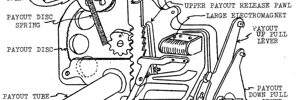
4 - 4 - THE PAYOUT MECHANISM The pay off mechanism of the Sportsman is part electrical and part mechanical. The advantages of having a mechanical element-are obvious. This eliminates the possibility of any series of contacts becoming stuck or short circuited and burning out the Battery, Electro magnets, etc. Varying the thicknesses of coins may at times cause binding in the payout mechanism and a strictly electrical payout would prevent any agitation, whereas a combination mechanical and electrical payout permits agitation and consequent release of the binding. Moreover, by making the payout partly mechanical we have eliminated the necessity of a motor. On the Sportsman there is no motor to burn out. The construction of the Sportsman Payout Device actually prevents payout of the entire tube. The balls entering the proper combinations on the playing field set up an electrical circuit which permits the player to get the correct award ONLY when he presses the lever or handle on the right hand side of the machine. By taking the payoff mechanically the player has automatically broken the circuit so that it cannot possibly pay-again until another winner appears. The principle of operation of the payout device is easily understandable. By referring to the illustration on Page 5, Figure 2, you will be able to follow the explaination easily. As the checks leave the coin chute they drop into a tube about six and one-half inches long, known as the payout tube. This tube leads directly to the Payout Disc immediately underneath. The Payout Disc is the exact thickness of three checks and has in it four holes. Each hole will perfectly accomodate the proper size checks. This Disc is movable and revolves when a winner appears and the payoff is taken. Thus it will be seen that the Sportsman pays off in units of three. Let us suppose that the player has put the balls in the proper holes to win three checks or tokens. This is what happens: Contacts are now made ready for taking the payout, but the circuit is not yet completed until the lever at the right of the machine is pressed down. This lever is directly connected to the Payout Rack Geer Segment. The moment the player starts to press down on the lever to take the payout and by so doing turns the Payout Rack Gear Segment, he permits the points on the Payout Circuit Breaker to make contact. This oontact sets the Payout Mechanism in motion. First of all, when the contact is made, an electrical current flows through the small electromagnet adjacent to Payout Stop Lever A. This draws the Payout Stop Lever down toward the Electromagnet. At the opposite end of each Payout Stop Lever you will notice a Contact Point. The Small Electromagnet, by drawing the Payout Stop Lever down, causes the contact point at the opposite end of the Stop Lever to make contact with another contact point. As soon as these two points make contact an electrical current flows through the Large Electromagnet which
5 - 5 - draws the Upper Payout Release Pawl toward the Large Electromagnet and away from the Payout Rack. At the same time the lower Payout Release Pawl goes up against the Payout Rack, preventing it from slipping back. All this happens simultaneously. As the player continues to press down on the lever he moves the Payout Rack forward toward the Payout Stop Levers. The Payout Rack, you will notice is connected to the movable Payout Disc by a gear. As the Payout Rack moves forward, it turns the Payout Disc so that the first hole in the Disc passes underneath the Payout Tube and cuts off three checks, When the Payout Rack has gone forward as far as it can go, which in this case is up to the Payout Stop Lever A, the circuit is broken, releasing the contacts on the other end of the Stop Lever. This causes the Upper Payout Release Pawl to move toward the Payout Rack and keeps the Payout Rack from moving forward any further. At the same time, the Tower Payout Release Pawl moves away from the Payout Rack, thus permitting the Rack to return to its original position. When the player releases the lever, thus permitting the payout Rack to return to its original position, the Rack turns the Payout Disc and the three checks that were cut off are dropped into the Payout Cup. Similarly, when a six winner appears, Payout Stop Lever B is drawn to the proper Electromagnet; when a nine winner appears, Payout Stop lever C is drawn to the Magnet; and when a twelve is won', Payout Stop Lever D is drawn to the Magnet. The Payout Rack goes just as far as the correct Payout Stop Lever, and as the Rack moves it revolves the Payout Disc the proper distance to pay out the correct number of checks. Toward the far end of the Pnyout Rack is the Payout Circuit Breaker. This, you will notice, is not making contact as long as the Payout Mechanism is not is use. However, as soon as the player turns the Payout Rack Gear Segment the slightest bit when he has a, winner the Payout Circuit Breaker is in proper contact. As soon as n payout is made and the Payout is in its original position, the circuit is again broken. This considerably lengthens the life of the batteries because there is no more contact after the payout is made. A winning combination could be left overnight or for weeks, yet no current would be consumed. Neither is any current used on a winner before the payout is made. The only time current is used is at the actual moment of taking the prayoff. This lasts for only a fraction of a second. The gap on the Payout Circuit Breaker is properly adjusted at the factory. The correct distance is approximately 1/32" or the thickness of two business caxds. If it becomes necessary to adjust the gap, do so by means of the Payout Circuit Breaker Adjusting Screw. Be sure the lock nut is tight before placing the machine in operation.

6 - 6 -
7 - 7 - CHECKING THE PAYOUT In checking the payout, should any trouble occur, FIRST OF ALL, see that there are sufficient checks in the Payout Tube. The next step is to test the Batteries to see that they are the proper amperage and not burned out. The Jennings Sportsman will not operate properly if the combined amperage of the Batteries is less than 30 amperes. Therefore, it is highly advisable for you to buy yourself a good, dependable amp-meter for the purpose of testing the batteries. Should they at any time fall below 30 amperes they will have to be replaced. Next, see that the metal ball rests on top of the post in the AntiTilting Device cup. If the ball falls off during the course of play the circuit will be broken and the machine will not pay off even when a winner appears. If the ball falls off during the course of play the circuit will be broken and the machine will not pay off even when a winner appears. If the ball falls off too easily it is probably because the table is not perfectly level. After you have made certain that the table is level and the ball still falls off it may be necessary to use a little sandpaper or emery cloth on the top of the post. Another solution would be to use a smaller metal ball. A possible yet simple cause of payout trouble may be the result of leaving the checks in the payout cup at the bottom of the machine. Should the player win the high awards a copule of time and press down on the lever at the right of the machine, but neglect to take the checks from the payout cup, these checks may pile into the Payout Disc and keep the machine from paying out. Make certain that the payout cup is empty, thereby eliminating the possibility of a jammed Payout Disc. At the same time, look carefully for checks which may be standing up on end at the bottom of the Payout Tube. Be sure that the checks lie flat in the Tube. This may be seen by looking through the slits or holes in the Brass Payout Tube. The next thing to look for is loose or broken wiring. Carefully check over all the wiring, tighten all loose connections, and if any broken wires are found, splice them together and solder them if possible. Wrap a small piece of friction or adhesive tape around any spliced wires to prevent possible short circuits. Examine the Fuse carefully to see that it is in good condition, and replace it in the proper receptacle. Assuming that the Batteries, Anti-Tilting Device, Payout Cup, wiring and Fuse are all as they should be, that the machine is level and that there are enough checks in the payout Tube. Let us next test the coils or as they axe commonly known Electromagnets, located on the Payout Mechanism. There are five of these. Each Electromagnet has two wires leading out from the coil. To test, first connect a separate wire to each terminal of the Batteries. Place the two ends of these wires on the wires leading
8 - 8 - from the coil. Be sure a good contact is made on the bare wire. This completes the circuit and the Electromagnet will then operate, drawing toward it the proper lever. Should any of these Electromagnets fail to work they will need to be replaced. The five Electromagnets that are on the under side of the Playing Board are part of five Relay Switches. The four outside ones axe connected to the Payout Mechanism and control the quantity of checks that are paid out. The one in the center is connected to the Anti-Tilting Device. These relay Switches should be "closed" or making contact as long as the payout has not been taken or the machine tilted. These Relay Switches are reset by the Sliding Board when another coin is played into the machine. See Figure 3 below for illustration of Relay Switch in "closed" position. As soon as the pay off is taken and the circuit broken by the Payout Rack touching the Payout Stop Lever, the Electromagnet in the Relay Switch draws Lever A (shown in Figure 3 below) toward it and by so doing "opens" the Switch and separates the two Contact Points. This particular combination cannot pay again until another coin or check is played into the machine. Similarly, when the machine is tilted the center Relay Switch "opens" and breaks the circuit to the Payout Mechanism so that the machine cannot pay out until another coin or check is played.
9 - 9 - Test each of these five Relay Switches by first testing the Coil or Electromagnet and then test the contacts carefully to see that they are touching when the payout has not been taken. If these contacts do not touch adjust them so that they do, but see that they are separated when Lever A is against the Electromagnet. If the Relay Switch does not open when the Payout Rack makes contact with the Payout Stop Lever it will not permit the Payout Rack to be brought back to normal position. In other words, the machine will not pay out. Therefore, if Relay Switch will not open when Lever A releases Lever B, make sure that Lever B is not catching or sticking on some other point. On the next play, when the coin or check is inserted, the Sliding Board moves forward and resets the Relay Switches Should the Sliding Board Fail to reset the Relay Switches, loosen the lock nut on the Adjustment for Closing Relay Switches, make the necessary adjustment and tighten the lock nut. The next step in checking the payout is to try some actual winning combinations to see which one fails to pay off. Remove the top glass as explained on Page 2. Raise the Playing Board and let it rest on the Rod. Close the center Relay Switch with your finger. Place balls in one of the winning combinations. Nothing will happen as yet because there is still no contact. Press down on the lever on the right side of the cabinet, or if you prefer, turn the Payout Rack Gear Segment to which this lever is connected. If the pay off is working properly the correct number of checks will come out of the Payout Cup. By working slowly you can watch the action of the entire payout. The moment the Payout Rack Gear Segment is turned the slightest bit you will hear a click, This is made by the action of one of the Small Electromagnets drawing Payout Stop Lever A and the large Electromagnet drawing the Payout Release Pawl. These two work simultaneously By turning the Payout Rack Gear Segment the least bit you made contact on the Payout Circuit Breaker and this completed the circuit on the two Electromagnets. If the Small Elecomagnet draws Payout Stop Lever A and the Large Electromagnet
10 fails to draw the Upper Payout Release Pawl, examine the contact points at the other end of the Payout Stop Lever. These Points should make contact when the Small Electromagnet draws the Stop Lever. The contact that is made by these two contact points completes the circuit oil the Large Electromagnet. Therefore, it is important that these two points make proper contact. As you continue to turn the Payout Rack Gear Segment slowly you will see the Payout Rack moving forward and at the same time turning the movable Payout Disc to which it is by a gear. When you have turned the Payout Rack Gear Segment as far as it will go until the Payout Rack makes contact with Payout Stop Lever you will hear another click. This is one of the Electromagnets on the under side of the Playing Board drawing the Relay Switch open and breaking the contact. This contact remains broken until another coin or check is played. The Payout Disc, you will notice, has turned only far enough to release the proper number of checks. After you have checked the first Payout and noticed how it operates, check the others in the same manner. Should any of them fail to work, try lightly pressing the balls down against their contact points. The position of the Playing Board when raised up in the air may keep one or two balls from making proper contact. This condition, however, will be automatically remedied when the Playing Board is in its proper position. The weight of the balls themselves makes the contact. Figure 4, at the top of Page 9, is an illustration of the Ball Contact Unit that is used on the Sportsman. There are fourteen of these units riveted to the metal plate beneath the Playing, Board. When the ball goes into the proper hole, the weight of the ball closes the circuit on that particular Unit. The clearance of the Ball Contact Unit, when there is no Ball in position should be about the thickness of one or two business cards, as indicated on the sketch. Ball Contact Unit Figure 4 Should any payout combination still refuse to work properly even after you have made sure all the proper holes have been filled, examine the contacts on the Ball Contact Units. If the weight of the ball does not make contact on any Unit, use a long nose pair of pliers and bend the lever as indicated to make the contact. Be careful not to bend it too much or it will make contact even when there is no ball in place. DO NOT TAMPER WITH THESE BALL CONTACT UNITS UNLESS EVERY OTHER REMEDY HAS FAILED TO CORRECT PAYOUT TROUBLE These units are properly adjusted at the factory and there is very little possibility of their being out of order.
11 After you have determined that one of the winning combinations refuses to pay out, you can easily locate the source of the trouble by testing with a Trouble Lamp. One of these Lamps can be made very easily for a total cost of about fifteen cents. First, secure a radio pilot light and two lengths of wire each about three feet long. Solder the end of one of these wires to the brass threaded part of the pilot light. To the center bottom contact of the pilot light solder one end of the other piece of wire, making sure that there is no contact between the two wires. Your Trouble Lamp will be similar in appearance to the illustration below, Figure 5. TROUBLE LAMP FIGURE 5 You are now ready to test one or more of the payout circuits underneath the Playing Board. First, remove the top glass and raise the Playing Board as previously explained. Remove the Wood Ball Return Board. Fasten the free end of either one of the wires of your Trouble Lamp to the metal wired part of the Fuse. This end will remain in this position throughout the test. Test your Trouble Lamp by touching the other wire to the Battery terminal opposite to the one to which the Fuse block is connected. It should light up. Be sure that all five of the Relay Switches are closed. Place balls in the "Skill Shot" hole and in each of the holes of the combination you wish to test. Press down on these balls lightly with your finger to insure proper contact of the Ball Contact Unit. To make doubly sure that the Ball Contact Units are making proper contact, insert a match stick or toothpick underneath the part that the ball rests on. It is important that these Ball Contact Units make good contact in order to conduct a successful test. Suppose that the six Payout or Rabbit combination is the one you wish to test. After you have put the balls in the winning combination you are ready to go ahead. Making sure that one end of your Trouble Lamp is still fastened to the Fuse Block, place the other end on the 6th terminal from the left, directly to the left of the center or Anti-Tilting Relay Switch. This terminal has a brown wire leading from it right to the Relay Switch. Trouble lamp should light up. If lamp does not light up at any one Point during the course of this test it is an indication of a break between the last point that the lamp lit up and the point where it did not light up.
12 Next place the free wire on the Anti-Tilting Device Relay Switch at the point where the brown wire from the 6th terminal touches the Relay switch. Then touch the wire to the opposite terminal of the Relay Switch. Follow the brown wire to the "skill Shot" Ball Contact Unit and touch your Trouble Lamp to each terminal of the Unit. Keep following the brown wire until it meets the first irst ball Contact Unit of the combination you are testing. In this case it would be the third one that the brown wire touches after the "Skill Shot" Unit, or the one that has a green wire on it. In the meantime, you will have touched your Trouble Lamp to the brown wire at every point that it comes in contact with the Ball Contact Units. Now follow the green wire to the other two Ball Contact Units in the Rabbit Combination. As you do this, touch your Trouble Lamp to both termonals of each Ball Contact Unit to make sure that the current is passing through. Continue to follow the green wire to where it touches the Relay Switch at the extreme right. Touch your Trouble Lamp wire to each terminal of this Relay Switch and then keep following the green wire to where it comes to the 'Terminal at the bottom of the Board. The green wire leads from this Terminal at the bottom of the Board. The green wire leads from this Terminal through the cable to the terminal Panel at the rear of the Payout Mechanism. (See Figure 2 on Page 5.) Touch your Trouble Lamp wire to the green wire where it make contact with the Terminal at the bottom of the Board and also where it makes contact on the Terminal Panel. Now follow the green wire through the Terminal Panel to where it makes contact on one of the Small Electromagnets or coils, touching your Trouble Lamp wire to the point of contact. You have now made the complete circuit of the six or Rabbit combinations on the Playing Board. Each of the other winning combinations can be tested in exactly the same manner, simply by following the color of the wire which belongs to any one combination. In. giving the Payout Mechanism proper care, see that all moving parts are oiled at intervals of about six months. Use a light machine oil that does not gum, Use the oil sparingly, being careful not to drench anything or to cause any short circuits. It is a good idea every 30 days to use a little emery paper on all the contact points to be sure that they are making perfect contact.. Particular care should be taken to see that all wires to moving parts are free from kinks, etc.
13 Be sure all of your contacts are tight, especially those on the Batteries. When replacing Batteries connect them as shown in Figure 6 below. When moving the Sportsman from one location to another, remove the Fuse from the lower receptacle and place it in the top receptacle. This will prevent burned out Batteries. When the machine is again set up and leveled, replace the Fuse in the wired receptacle. Should players fail to receive all ten balls, caution them to pull Coin Slide all the way out. Coin slide must be pulled ALL THE WAY OUT to deliver the balls properly. The Sportsman is designed to operate on 6 to 7 1/2 volts. When connecting new batteries be sure they are connected in series and NOT in parallel. The correct battery hookup is illustrated on Page 11, Figure 6. Should the batteries be connected to deliver too heavy a load the Fuse will blow out. The average player will soon become proficient enough to average approximately 50% payout. This percentage is great enough to appeal to the sporting instincts of the players, yet it is small enough to earn a good profit for the machine. The highest possible winner with ten balls is twenty-seven tokens. This combination may be made by putting one ball in the "Skill Shot" hole, three in the "Partridge" holes, three in the "Pheasant" holes and three in the "Rabbit" holes. The player, however, must take each payout as it appears. The following equipment is furnished loose with each Sportsman in addition to those parts that are fastened down. Four legs with adjustment screws attached Four aluminum castings to go over the legs Eight Acorn-Headed Bolts Twelve White Balls Two Hundred Special Checks Two sets of Keys Four buttons for non-paying holes One plunger spring for steel balls Check this list and see that you have received all the parts shown. This is all the equipment you need to operate your Sportsman for some time.
14 TO SET SPORTSMAN FOR CASH PLAY Lift up Playing Board so it is supported by Rod. Remove screw from Hole No. 1 as shown on sketch. Push Stamping forward until Hole No. 2 occupies same position as previously occupied by Hole No. 1. Replace screw. Replace brass Magnet on Coin Chute with small black Magnet you will find tacked on to the side of the cabinet. See sketch for position of Magnet. To set for check play, reverse the procedure.
15 - 15 -
16 If you find that players are putting too many balls in the nonpaying holes, cover them up as shown in Figure 8 below. buttons buttons
17 Figure 1 CUT-AWAY VIEW OF THE SPORTSMAN
DIRECT DRIVE DIXIE DOUBLE SEAMER Model 25D
 OPERATOR'S MANUAL DIRECT DRIVE DIXIE DOUBLE SEAMER Model 25D LUBRICATE DAILY: A. Gears inside gear housing at chuck shaft (1) Oil B. Seam rolls and cam rolls (4) - Oil C. Seam roll levers through gear
OPERATOR'S MANUAL DIRECT DRIVE DIXIE DOUBLE SEAMER Model 10D
 OPERATOR'S MANUAL DIRECT DRIVE DIXIE DOUBLE SEAMER Model 10D OIL DAILY: A. Gears inside gear housing through oil groove in gear housing at cut surface of chuck shaft. (Oil through #517 gear housing cover
Model 23H Hand Crank Seamer
 OPERATOR'S MANUAL Model 23H Hand Crank Seamer If you are not experienced with your seamer, please read and understand this manual before operating the machine. If you have a question discuss it with your
3/8" Dr. Air Butterfly Impact Wrench
 8192106 3/8" Dr. Air Butterfly Impact Wrench Owner s Manual Read and understand all instructions before use. Retain this manual for future reference. Specifications Construction: Polished aluminum and
Lectric Cycles Mid-Drive Electric Motor Installation
 Lectric Cycles Mid-Drive Electric Motor Installation This write-up describes the installation of a Lectric Cycles electric motor. The model is the e-rad Mid-Drive 750 Watt conversion kit, installed on
Misaligned Folds Paper Feed Problems Double Feeds Won t Feed FLYER Won t Run iii
 Operator s Manual Table of Contents Operator Safety... 1 Introduction... 2 Unpacking and Setup... 3 Unpacking... 3 Setup... 4 FLYER Overview... 5 FLYER Diagram... 5 Capabilities... 5 Control Panel... 6
When your Rock-N-Bowl was shipped from the factory, the dipswitches were set as follows:
 WELCOME! Please take a moment to read the following before turning on your new Rock-N- Bowl game for the first time. Your game was carefully checked at the factory before shipping. After removing the game
Operation Manual Guillotine Cutter RC-5
 Operation Manual Guillotine Cutter RC-5 Technical Specifications General Safety/Operating Instructions Using the Guillotine Cutter/Crimper Blade Change Instructions Maintenance Instructions This is a detailed
Repair instructions. Pivot bushing replacement. XL-AS10001RM-en-DE Rev B
 Repair instructions Pivot bushing replacement XL-AS10001RM-en-DE Rev B Table of contents Table of contents 1 General information... 3 1.1 Safety information...3 1.2 Legal information...4 1.3 Order and
Parts of the Gun. Specifications XCR-C XCR-L. Optic Rail. Charging Handle. Sling Loop. Accessory Rails. Crane Stock. Flash Hider. Stock Pad.
 BEFORE USING THIS PRODUCT, CAREFULLY READ THOUGH MANUAL AND RETAIN IT FOR FUTURE REFERENCE. ECHO1USA AUTOMATIC ELECTRIC GUNS ARE INTENDED FOR AGES 18 AND ABOVE. THIS PRODUCT MAY CAUSE SERIOUS INJURY IS
ASSEMBLY GUIDE: Izip & Ezip Electric Bicycles with Rack-Top Mounted Batteries ( RTMB Bicycles )
") ASSEMBLY GUIDE: Izip & Ezip Electric Bicycles with Rack-Top Mounted Batteries ( RTMB Bicycles ) Please Refer to your Owner s Manual for Detailed Setup Instructions Technical & Customer Service: 1-800-377-4532
ASSEMBLY GUIDE: Izip & Ezip Electric Bicycles with Rack-Top Mounted Batteries ( RTMB Bicycles ) Please Refer to your Owner s Manual for Detailed Setup Instructions Technical & Customer Service: 1-800-377-4532
OPERATOR'S MANUAL Model 23 or 24 Belt Drive Electric Seamer
 OPERATOR'S MANUAL Model 23 or 24 Belt Drive Electric Seamer Model 23-500 (shown) If you are not experienced with your seamer, please read and understand this manual before operating the machine. If you
MRF SERIES. Instruction Manual
 MRF SERIES Instruction Manual BEFORE USING THIS PRODUCT, CAREFULLY READ THOUGH MANUAL AND RETAIN IT FOR FUTURE REFERENCE. ECHO1USA AUTOMATIC ELECTRIC GUNS ARE INTENDED FOR AGES 18 AND ABOVE. THIS PRODUCT
Read Before Operating!
 Read Before Operating! IMPORTANT OPERATING INSTRUCTIONS THE DEUCE PITCHING MACHINE THROWS REAL REGULATION BALLS; HOWEVER, THE ACCURACY OF THE DEUCE DEPENDS ON THE QUALITY, HARDNESS AND TYPE OF BALLS YOU
Read Before Operating!
 Read Before Operating! IMPORTANT OPERATING INSTRUCTIONS THE DEUCE PITCHING MACHINE THROWS REAL REGULATION BALLS; HOWEVER, THE ACCURACY OF THE DEUCE DEPENDS ON THE QUALITY, HARDNESS AND TYPE OF BALLS YOU
User Manual GRI- 1500Li
 User Manual GRI- 1500Li Your Cart Tek caddy cart was thoroughly quality control checked and road tested before being shipped to your address. We do everything possible to assure that your caddy is in perfect
OPERATOR'S MANUAL DIRECT DRIVE DIXIE DOUBLE SEAMER. Model 25D
 OPERATOR'S MANUAL DIRECT DRIVE DIXIE DOUBLE SEAMER Model 25D OPERATOR'S MANUAL DIRECT DRIVE DIXIE DOUBLE SEAMER MODEL 25D INTRODUCTION DESCRIPTION Dixie Model 25D series of double seamers are adaptable
Chapter 2 Rigging. Cutting Wire Rope. Anchoring Wire Rope to Drum. Winding Wire Rope Onto Drum
 Chapter 2 Rigging Cutting Wire Rope The wire rope must be tightly seized on both sides of the point where the wire rope will be cut, as shown in Figure 2-1. Seize the wire rope with either seizing wire
ST Shimano Total Integration. Technical Service Instructions. General Safety Information SI-6CT0B
 Technical Service Instructions SI-6CT0B t ST-4400 Shimano Total Integration Shimano Total Integration Features The Shimano Total Integration TIAGRA series features a dual action control lever which actuates
HOLLISTER-WHITNEY ROPE GRIPPER
 HOLLISTER-WHITNEY ROPE GRIPPER Instructions for Model #620GA1, 620GA2 (US PATENT 8,511,437) WARNING: KEEP HANDS CLEAR OF ROPE GRIPPER. FORCES CREATED CAN CRUSH FINGERS. Figure 1 ROPE GRIPPER TM MOUNTING
OPERATION AND FUNCTIONING
 C1, FM 23-65 * CHAPTER 3 OPERATION AND FUNCTIONING This chapter explains the operation of the MG. It discusses the loading, unloading, and clearing procedures, and the cycle of functioning of the weapon.
Final Assembly Instructions Bikes with Quill Stems
 Final Assembly Instructions Bikes with Quill Stems Thank you for buying your new bicycle from L.L.Bean. Read these instructions carefully before beginning the final assembly. Prior to shipping, our expert
INSTRUCTION MANUAL CZ 630/631
 INSTRUCTION MANUAL CZ 630/631 Before handling the air rifle read this manual carefully and observe the following safety instructions. Improper and careless handling of the air rifle could result in unintentional
NICROS-GRANITPANELS INSTALLATION MANUAL
 NICROS-GRANITPANELS INSTALLATION MANUAL NICROS, INC. 845 PHALEN BLVD. ST. PAUL, MN 55106 PHONE: 651.778.1975 FAX: 651.778.8080 THANK YOU FOR YOUR PURCHASE OF THIS NICROS PRODUCT Nicros-GranitPanels are
MUELLER. A Wall Type. Indicator Post. Reliable Connections. General Information 2. Technical Data/ Dimensions 3. Installation 4-5.
 Installation Instructions manual MUELLER table of contents PAGE A-20814 Wall Type General Information 2 Technical Data/ Dimensions Installation 4-5 Maintenance 6 Parts 7 Indicator Post! WARNING: 1. Read
CHAINLESS ANCHORING SYSTEM USER MANUAL
 CHAINLESS ANCHORING SYSTEM USER MANUAL Introduction..................................................... 1 Setting up the Chainless Anchoring System............................ 4 Set up Procedure............................................
LIFTING MAGNETS ERIEZ MAGNETICS
 MJ-2300E Installation, Operation and Maintenance Instructions LIFTING MAGNETS ERIEZ MAGNETICS HEADQUARTERS: 2200 ASBURY ROAD, P.O. BOX 10608, ERIE, PA 16514 0608 U.S.A. WORLD AUTHORITY IN ADVANCED TECHNOLOGY
INSTRUCTION MANUAL. Slavia 630/631
 INSTRUCTION MANUAL Slavia 630/631 Before handling the air rifle read this manual carefully and observe the following safety instructions. Improper and careless handling of the air rifle could result in
Gerber Sabre 404 and 408 Installation Instructions
 1 TITLE: Gerber FastFact # Supplied by: Last Modified: Summary: Gerber Sabre 404 and 408 Installation Instructions 5002 Gerber Service November 13, 2001 This document provides the installation and set-up
O P E R ATING INSTRUCTIONS FOR MODEL SPR-45 Automatic Screen and Stencil Printer
 O P E R ATING INSTRUCTIONS FOR MODEL SPR-45 Automatic Screen and Stencil Printer TABLE OF CONTENTS I. SPECIFICATIONS...3. II. SAFETY INSTRUCTIONS...4. III. INSTALLATION...5. IV. SET-UP...6. V. SYSTEM OPERATION...9.
-Round Down- Description & Overview. VEX Classroom Competition Round Down
 -Round Down- Description & Overview Round Down is a head-to-head robotics competition designed and scaled to be run in a classroom environment by a single teacher. This game provides a challenge for designers
USER MANUAL
 C Cimarron Sports 1-888-816-6517 www.cimarronsports.com Combo Pitching Machine USER MANUAL TABLE OF CONTENTS Thank you for purchasing the Cimarron Combo Pitching Machine. The Cimarron Combo Pitching Machine
I.H.S INSTALLATION INSTRUCTIONS
 I.H.S INSTALLATION INSTRUCTIONS TOOLS REQUIRED The following tools will be required for installation of your I.H.S. system. Item Qty Needed 9/16 Open End Wrench 2 3/4 Open End Wrench 1 1/2 Open End Wrench
AR STYLE FIREARMS OWNER'S MANUAL: OPERATION, HANDLING, DISASSEMBLY / REASSEMBLY & SAFETY INSTRUCTIONS
 AR STYLE FIREARMS OWNER'S MANUAL: OPERATION, HANDLING, DISASSEMBLY / REASSEMBLY & SAFETY INSTRUCTIONS - DO NOT DISCARD THIS MANUAL - READ THIS MANUAL CAREFULLY, PAYING CLOSE ATTENTION TO THE INSTRUCTIONS
Pectoral Machine. User manual E S S E N T I A L S T R E N G T H
 E L E M E N T and the cable E S S E N T I A L S T R E N G T H User manual 1 and the cable and The identification plate of and manufacturer, affixed on the back panel of the weight stack, gives the following
MANUAL SEALLESS STEEL STRAPPING TOOL MODEL A
 OPERATION MANUAL / SPARE PARTS LIST MANUAL SEALLESS STEEL STRAPPING TOOL MODEL A337.0001 13.1912.01 13191201.en/MAS/ 10.02 INDEX PAGE 1 SAFETY INSTRUCTIONS 2 2 WARRANTY CONDITIONS AND LIABILITY 4 3 APPROPRIATE
Setup Guide for your HVO Naked Drone
 Setup Guide for your HVO 60 + 60 Naked Drone 1 The Big Picture 1. Choose The System Location 2. Get the Power Ready 3. Get an Approved Oxygen Regulator 4. Get the Tools You ll Need 5. Unpack the crate
Ecomow Electric Mower
 Ecomow Electric Mower 1100 Watt Operation Manual 2 Year Replacement Warranty ECO-320 - Type 1 0509 To view the entire range visit: www.ozito.com.au SPECIFICATIONS - MODEL NO. ECO-320 Motor Size: 1100W
VERSA BIKE RACK INSTRUCTIONS
 VERSA BIKE RACK INSTRUCTIONS Models #8, 8 Important This rack is designed for use with a or. receiver hitch. The rack is designed to hold a maximum of two bicycles. Do not use it for anything other than
by Master Halco ANCHOR GATE SYSTEMS Swing Gates Overhead Slide Gates Cantilever Slide Gates Vertical Lift Gates Fencing Without Boundaries.
 by Master Halco ANCHOR GATE SYSTEMS Swing Gates Overhead Slide Gates Cantilever Slide Gates Vertical Lift Gates Fencing Without Boundaries. The Better Way To Build Your Cantilever Slide Gates... The Principle
Final Assembly Instructions Bikes with Threaded Headsets
 Final Assembly Instructions Bikes with Threaded Headsets Thank you for buying your new bicycle from L.L.Bean. Read these instructions carefully before beginning the final assembly. Prior to shipping, our
Troyer s Gourd Rack 8 unit F R H O P
 B E A D I M-N L Vertical Parts F R H O P Horizontal Parts C G J Updated 11/16 Parts List A: Top of Pole B: Bottom of Pole C: 48 Ground Stake D: Top Perch rods 48 long E: Hub F: Rope Winder w/ attached
Paddle Bar Replacement
 This procedure is to help facilitate the replacement of the 23 Paddle Bar Assembly on the ANKOM Dietary Fiber Analyzer. Note: The following items will be sent in a replacement package as part of the 23
MAGNETIC CYCLING TRAINER SF-B0419 USER MANUAL
 MAGNETIC CYCLING TRAINER SF-B049 USER MANUAL IMPORTANT: Read all instructions carefully before using this product. Retain owner s manual for future reference. For customer service, please contact: support@sunnyhealthfitness.com
QUALITY ALUMINUM BOAT LIFTS, INC. INSTRUCTIONS. Dominator Lake Lift
 INSTRUCTIONS Dominator Lake Lift PHONE:251-986-3882 * FAX:251-986-3136 QABLDOMINATORINST.2014 P a g e 1 Quality Aluminum Boat Lifts, INC. Installation Instructions: Dominator Lake Lift Thank you for your
Pachinko Game (Additional Information)
") Spiral Slide Lock Tab Front Door Brass Nails California Antique Slots, Inc. (805) 583-0785 (FAX) "Winner" Light Loader Levers Seesaw Covers Track Covers Bumpers Stickers Spinners Tulips Pockets Glass Cover
Spiral Slide Lock Tab Front Door Brass Nails California Antique Slots, Inc. (805) 583-0785 (FAX) "Winner" Light Loader Levers Seesaw Covers Track Covers Bumpers Stickers Spinners Tulips Pockets Glass Cover
Parts List. Description. Additional Considerations. Installation Instructions. Dual/Elite Hydraulic Treadmill Kit (supplied by EPI)
") Page 1 of 9 Parts List Dual/Elite Hydraulic Treadmill Kit (supplied by EPI) Qty Description Treadmill Body 1 Treadmill Power Unit (per Treadmill Body) 2 Treadmill Decks (per Treadmill Body) 1 Treadmill
Page 1 of 9 Parts List Dual/Elite Hydraulic Treadmill Kit (supplied by EPI) Qty Description Treadmill Body 1 Treadmill Power Unit (per Treadmill Body) 2 Treadmill Decks (per Treadmill Body) 1 Treadmill
600 / 600FC OWNER'S MANUAL
 PROGRESSION 600 / 600FC OWNER'S MANUAL Issue 2 / Version E - Dec. 10, 1997 Copyright 1997 GAMMA Sports - All Rights Reserved PROGRESSION 600 / 600FC OWNER'S MANUAL TABLE OF CONTENTS PAGE 1... WARRANTY
WIND CLIPPER KTS ILLUM SCALE INC DEC CLIPPER WIND SYSTEM
 CLIPPER WIND KTS ILLUM SCALE DEC INC CLIPPER WIND SYSTEM TABLE OF CONTENTS INTRODUCTION PRE-TEST OF INSTRUMENT INSTALLING THE MASTHEAD SENSOR UNIT INSTALLING THE DISPLAY NORMAL OPERATION CHANGING THE
Pressure Dump Valve Service Kit for Series 3000 Units
 Instruction Sheet Pressure Dump Valve Service Kit for Series 000 Units. Overview The Nordson pressure dump valve is used to relieve hydraulic pressure instantly in Series 00, 400, 500, and 700 applicator
222 Schwinn Recumbent Exercise Bike Parts List Full Size Hardware Chart Product Illustration Assembly Instructions
 222 Schwinn Recumbent Exercise Bike Parts List Full Size Hardware Chart Product Illustration Assembly Instructions FITNESS SAFEGUARDS AND WARNINGS Before starting any exercise program, consult with your
VL 2K LIFT D-L WINCH INSTRUCTIONS (Applies to P/Ns , , , , , )
") VL 2K LIFT D-L WINCH INSTRUCTIONS (Applies to P/Ns 3714022, 3714028, 3714034, 3714040, 3714043, 3714046) REIMANN & GEORGER CORPORATION MARINE PRODUCTS BUFFALO, NY P/N 6112103 04/09/18 1 SAFETY 1.1 INTRODUCTION
VL 2K LIFT D-L WINCH INSTRUCTIONS (Applies to P/Ns 3714022, 3714028, 3714034, 3714040, 3714043, 3714046) REIMANN & GEORGER CORPORATION MARINE PRODUCTS BUFFALO, NY P/N 6112103 04/09/18 1 SAFETY 1.1 INTRODUCTION
Model 130M Pneumatic Controller
 Instruction MI 017-450 May 1978 Model 130M Pneumatic Controller Installation and Operation Manual Control Unit Controller Model 130M Controller is a pneumatic, shelf-mounted instrument with a separate
Cleaning rod: spring steel, stainless steel or carbon fibre cleaning rod - only use a one-piece rod. Avoid using snakes.
 Telemark Biathlon Where performance and precision come together http://telemarkbiathlon.com Rifle Cleaning Date : July 19, 2013 Anschutz Rifle Manual - Click Here Izhmash 7-3 Rifle Manual - still looking
PRODUCT SUPPORT MANUAL YACHT BEAM 6M Searchlight Remote Control System with Joystick Remote Control Panel
 PRODUCT SUPPORT MANUAL YACHT BEAM 6M Searchlight Remote Control System with Joystick Remote Control Panel The Yacht Group - 4545 Ponce de Leon Blvd. Coral Gables FL 33146 Tel. 305.667.5811 - Fax. 305.663.5551
BATA-1 Twin Pitch. Pitching Machine
 BATA-1 Twin Pitch Pitching Machine The Twin Pitch machine is basically two BATA-1 machines mounted on one stand, with one exception. The machine heads are a mirror image of each other. The set-up and operations
Installation Instructions Air Compressor Part # 2780, 2781
 Note: It is essential that the operator of this product read and understand the contents of this manual before installing and using this product. Parts Included Qty Parts Included Qty Compressor 1 Coil
accidents which arise due to non-observance of these instructions and the safety information herein. SPECIFICATIONS
 18 GAUGE 1-1/4 INCH BRAD NAILER Model: 7611 CALIFORNIA PROPOSITION 65 WARNING: You can create dust when you cut, sand, drill or grind materials such as wood, paint, metal, concrete, cement, or other masonry.
A U T O O P E N S E R I E S C A P P R E S S O P E R A T O R S M A N U A L
 A U T O O P E N S E R I E S C A P P R E S S O P E R A T O R S M A N U A L Safety Instructions When using your heat press, basic precautions should always be followed, including the following:.. 3. 4. 5.
Thanks for shopping with Improvements! 20 Reel Mower with Catcher Item #
 Thanks for shopping with Improvements! 20 Reel Mower with Catcher Item # 411837 To order, call 1-800-642-2112 West Chester, OH 45069 0313 If you have any questions regarding this product, call 1-800-642-2112
Maintenance Manual. Note: This document is broken up into the following 6 sections of prescribed maintenance.
 How to Perform Maintenance On LPKF Circuit Board Plotters Requirements - LPKF Circuit Board Plotter - BoardMaster Software - 2.5 mm Allen wrench (for earlier model machines) - 3mm Allen Wrench - 4mm Allen
HACK ATTACK PITCHING MACHINE PATENTS APPLIED FOR INSTRUCTION MANUAL. Includes: OPERATION SETUP USE & CARE SERVICE
 Baseball Pitching Machines Baseball HACK ATTACK PITCHING MACHINE PATENTS APPLIED FOR INSTRUCTION MANUAL Includes: OPERATION SETUP USE & CARE SERVICE REV 083115 Sports Attack, LLC. 800-717-4251 sportsattack.com
Thank you for purchasing your new Empire Reloader B Sound-Activated 3-Speed Paintball Hopper!
 Thank you for purchasing your new Empire Reloader B Sound-Activated 3-Speed Paintball Hopper! Should you require any technical assistance on the use of this product, or if your product needs servicing,
Assembly, Fitting, Care & Maintenance
 Assembly, Fitting, Care & Maintenance Assembly 1.1 Remove All Parts and Tools from Packaging 1.2 Part and Tools required for assembly 1.3 Check Foot & Leg Assembly 1.4 Adjust Upper-Leg-Support (ULS) Height
Syringe, Distribution Valve and Infusion Pump Removal/Replacement ATTENTION SYRINGE REPLACEMENT
 ATTENTION SYRINGE REPLACEMENT Please read through the document completely before starting any repairs. Refer to the proper section in the service manual for complete removal and replacement procedures.
IMPORTANT PLEASE READ BEFORE COMMENCING INSTALLATION
 IMPORTANT PLEASE READ BEFORE COMMENCING INSTALLATION This Fitting Guide is designed to assist in the Installation of your Reverse Osmosis System. Some of the parts that are supplied with each system may
OWNER'S MANUAL. Copyright 2003 GAMMA - All Rights Reserved
 OWNER'S MANUAL AL Issue 1 - December 2003 Copyright 2003 GAMMA - All Rights Reserved OWNER'S MANUAL TABLE OF CONTENTS PAGE 1... WARRANTY PAGE 2... ASSEMBLY INSTRUCTIONS PAGE 4... MOUNTING THE RACQUET PAGE
400C & 450C DUAL PERFORMANCE VALUE PACKS
 (Chrome) PART NO. 40013 (Silver) PART NO. 45012 (Chrome) PART NO. 45013 IMPORTANT: It is essential that you and any other operator of this product read and understand the contents of this manual before
Stone Container 987 Auger Packer Manual
 Stone Container 987 Auger Packer Manual SAFETY INSTALLATION OPERATION MAINTENANCE, Ltd. (512) 352-3694 Phone (512) 352-3648 Fax 1 Table of Contents Topic Reconditioned Machine Information Page Insert Chapter
User Instruction Manual
 User Instruction Manual 4500 psi Air Compressor Ver 2, 1.18 Contents Parts Included...3 Assembly Instructions...3-5 Operation Instructions...6-7 Oil Change Intervals...8 Air Filter Replacement...9 Setting
MOTORWORKS SUBMARINE MODIFICATIONS
 MOTORWORKS SUBMARINE MODIFICATIONS PART I STANDARD SUBMARINE OPERATION AND SETUP NO MODIFICATIONS. IF YOU WISH TO MODIFY YOUR SUBMARINE FOR DEEP OPERATIONS (BELOW 3 METERS) SKIP TO PART II PLEASE FOLLOW
American Flagpole & Flag Co. 1(800)
") SENTRY CONCEALED HALYARD-REVOLVING TRUCK GROUND SET INSTALLATIONS INSTRUCTIONS 1. Dig foundation as detailed in SECTION A FOUNDATION SPECIFICATIONS, set sleeve in enter of hole with top 2 above grade.
SENTRY CONCEALED HALYARD-REVOLVING TRUCK GROUND SET INSTALLATIONS INSTRUCTIONS 1. Dig foundation as detailed in SECTION A FOUNDATION SPECIFICATIONS, set sleeve in enter of hole with top 2 above grade.
HOLLISTER-WHITNEY ROPE GRIPPER
 HOLLISTER-WHITNEY ROPE GRIPPER Instructions for Model #620GA1, 620GA2 (Patented worldwide, other patents pending) WARNING: KEEP HANDS CLEAR OF ROPE GRIPPER. FORCES CREATED CAN CRUSH FINGERS. Figure 1 ROPE
icreasepro Creaser Operators Manual
 6-2013 Version 3.0 icreasepro Creaser Operators Manual WWW.MBMCORP.COM 800-223-2508 TABLE OF CONTENTS SPECIFICATIONS.1a SAFETY PROCEDURES/CARE & MAINTENANCE..1b COMPONENT IDENTIFICATION 2 TOUCH SCREEN
Installation Guide, MPower Echelon Console
 Installation Guide, MPower Echelon Console AC Performance, AC Sport and AC Performance Plus Schwinn Echelon Console (External Routing) 1. Install batteries to console. Mount the console to the bike. 2.
8MAY15 US RACK, Inc Falcon Drive, Madera, CA
 8MAY15 US RACK, Inc. - 2850 Falcon Drive, Madera, CA 93637-559-661-3050 INSTRUCTIONS for Bedrail-mounted MOTORCYCLE RACK, Model 2001-4TRA WARNING: Do NOT attempt to install or use this rack without following
For ANCHOR WINCH Model: T Big Water 45 T sw Salt Water Series Big Water 45
 INSTALLATION AND OPERATING INSTRUCTIONS ANCHOR WINCHES For ANCHOR WINCH Model: T10110-45 Big Water 45 T10103-45sw Salt Water Series Big Water 45 If you have any questions or difficulty installing this
For ELECTRIC ANCHOR WINCH Models: T Pontoon 35 T sw Salt Water Series Coastal 35
 INSTALLATION AND OPERATING INSTRUCTIONS ANCHOR WINCHES For ELECTRIC ANCHOR WINCH Models: T10109-35 Pontoon 35 T10102-35sw Salt Water Series Coastal 35 If you have any questions or difficulty installing
2,500/4,000 LB Easy Riser Vertical Cable Feighner Lift
 2,500/4,000 LB Easy Riser Vertical Cable Feighner Lift CAUTION - PUT SAFETY FIRST 1. Before attempting to install or operate this lift, study and fully understand the proper operating procedures and safety
602 STRINGING MACHINE OWNER'S MANUAL
 PROGRESSION 602 STRINGING MACHINE OWNER'S MANUAL AL Issue 1- April 2000 Copyright 2000 GAMMA Sports - All Rights Reserved PROGRESSION 602 STRINGING MACHINE TABLE OF CONTENTS PAGE 1... WARRANTY PAGE 2...
OWNER'S MANUAL. Copyright 1999 ATS - All Rights Reserved
 OWNER'S MANUAL AL Issue 2 - August 19, 1999 Copyright 1999 ATS - All Rights Reserved OWNER'S MANUAL TABLE OF CONTENTS PAGE 1... WARRANTY PAGE 2... ASSEMBLY INSTRUCTIONS PAGE 4... MOUNTING THE RACQUET PAGE
INSTALLATION AND OPERATING INSTRUCTIONS. T10219-AD Deckboat 40 with AutoDeploy and Wireless Remote Control
 INSTALLATION AND OPERATING INSTRUCTIONS ANCHOR WINCH T10219-AD Deckboat 40 with AutoDeploy and Wireless Remote Control If you have any questions or difficulty installing this product, we are here to help!
Inside Front cover This page will remain blank.
 Owner s Manual Inside Front cover This page will remain blank. 1 Table of Contents Parts of the AirCAT...3 Assembling the AirCAT...4 Attaching the wheels to the stand...4 Attaching the battery box to the
444C DUAL PERFORMANCE VALUE PACK
 (Chrome) PART NO. 44432 IMPORTANT: It is essential that you and any other operator of this product read and understand the contents of this manual before installing and using this product. SAVE THIS MANUAL
CLASS CYCLE P8000 OWNER'S MANUAL JOHNSON HEALTH TECH. CO., LTD.
 CLASS CYCLE P8000 JOHNSON HEALTH TECH. CO., LTD. No.26, Ching Chuan Rd., Taya Hsiang, Taichung Hsien 428, Taiwan, R.O.C. TEL: +886-4-2566700 FAX: +886-4-2560087 E-mail: sales@johnsonfitness.com http://www.johnsonfitness.com
accidents which arise due to non-observance of these instructions and the safety information herein. SPECIFICATIONS
 18 GAUGE 2 INCH BRAD NAILER Model: 7555 CALIFORNIA PROPOSITION 65 WARNING: You can create dust when you cut, sand, drill or grind materials such as wood, paint, metal, concrete, cement, or other masonry.
User's Manual. MixRite TF 10. Edition 05.08
 User's Manual MixRite TF 10 Edition 05.08 1 Tefen MixRite TF 10 fertilizer and chemicals Injector Congratulations on your purchase of one of Tefen s high quality products. To get the best results from
Assembly Tools. Assembly will take about an hour
 Assembly Guide Assembly Tools Included in your parts box: Pedals Toolkit (4+5mm combo Allen wrench, 13+15mm combo open-end wrench) Touch-up paint Spare fuses (for battery) Assembly will take about an hour
TWIST-IN STEPPER SF-S0636 USER MANUAL
 TWIST-IN STEPPER SF-S0636 USER MANUAL IMPORTANT! Please retain owner s manual for maintenance and adjustment instructions. Your satisfaction is very important to us, PLEASE DO NOT RETURN UNTIL YOU HAVE
FRONT DERAILLEUR - CURRENT RANGE
 FRONT DERAILLEUR - CURRENT RANGE (since 2015) (since 2018) (since 2017) (since 2018) WARNING! This technical manual is intended for use by professional mechanics. Anyone who is not a qualified professional
E-trike Li Assembly Guide
 PREPARATION 1. Read this assembly manual BEFORE commencing assembly. 2. Carefully remove all the components and packaged hardware from the shipping boxes. 3. Unpack the contents of the large double box
PR4 Installation, Operation & Maintenance Instructions (DOT Certification Included)
") PR4 Installation, Operation & Maintenance Instructions (DOT Certification Included) March 2006 Form FVC 054 Rev. 6 KEEP THIS DOCUMENT WITH THE PRODUCT UNTIL IT REACHES THE END USER. The Passive - R4 device
PR4 Installation, Operation & Maintenance Instructions (DOT Certification Included) March 2006 Form FVC 054 Rev. 6 KEEP THIS DOCUMENT WITH THE PRODUCT UNTIL IT REACHES THE END USER. The Passive - R4 device
To Purchase This Item, Visit BMI Gaming (800)
") How to play the game How to play the game The object of the game is to reach the Game Goal before your opponent. HOW TO START: - A coin toss decides who starts the game. The winner of the coin toss also
How to play the game How to play the game The object of the game is to reach the Game Goal before your opponent. HOW TO START: - A coin toss decides who starts the game. The winner of the coin toss also
X-6 STRINGING MACHINE OWNER'S MANUAL. Issue 1 - May Copyright 2004 GAMMA Sports - All Rights Reserved
 X-6 STRINGING MACHINE OWNER'S MANUAL Issue 1 - May 2004 Copyright 2004 GAMMA Sports - All Rights Reserved OWNER'S MANUAL GAMMA X-6 TABLE OF CONTENTS PAGE 1... WARRANTY PAGE 2... FEATURES PAGE 3...ASSEMBLY
SEADUCER BOATS GAS MONO COME VISIT US ON THE WEB AT
 SEADUCER BOATS GAS MONO COME VISIT US ON THE WEB AT WWW.SEADUCERBOATS.COM 1 - Pkg. Of 440 push rod ends 1 - Pkg. of solder-on rod ends 2 -water outlet fitting 1-1/4" prop nut 1 -.250" x 24" flex shaft
SANTANA STOWAWAY TANDEM WITH AIRLINER SAFECASE AND FTS FOAM TRAY SYSTEM ASSEMBLY AND DISASSEMBLY
 SANTANA STOWAWAY TANDEM WITH AIRLINER SAFECASE AND FTS FOAM TRAY SYSTEM ASSEMBLY AND DISASSEMBLY Congratulations! You are now the proud owner of the world s most travel-ready, performance tandem. The following
Front derailleur. Dealer's Manual SORA FD-R3000 FD-R3030 CLARIS FD-R2000 FD-R2030. ROAD MTB Trekking. City Touring/ Comfort Bike DM-RBFD001-01
 (English) DM-RBFD001-01 Dealer's Manual ROAD MTB Trekking City Touring/ Comfort Bike URBAN SPORT E-BIKE Front derailleur SORA FD-R3000 FD-R3030 CLARIS FD-R2000 FD-R2030 CONTENTS IMPORTANT NOTICE... 3 TO
OWNER'S MANUAL FREE FALL ROPE AND CHAIN ANCHOR WINCH. 12 Volt Powered Winch Power-In / Freewheel-out operation. 36', 41' and 46' Class Anchor Winch
 OWNER'S MANUAL 36', 41' and 46' Class Anchor Winch FREE FALL ROPE AND CHAIN ANCHOR WINCH PW46101 12 Volt Powered Winch Power-In / Freewheel-out operation These instructions apply to all models listed.
632 AccuPro Set-up & Operation
 632 AccuPro Set-up & Operation Always check: Reel & Roller bearings Bent or broken blades Make sure the reel spins freely in the frame Place the Reel Into the Machine There are three lifting options for
Final Assembly Instructions Bikes with Threaded Headsets
 Final Assembly Instructions Bikes with Threaded Headsets Thank you for buying your new bicycle from L.L.Bean. Read these instructions carefully before beginning the final assembly. Prior to shipping, our