FIELD GUIDE. for the Airport Pavement Maintenance Recommendation Tool for ACRP Report 159 AIRPORT COOPERATIVE RESEARCH PROGRAM
|
|
|
- Geoffrey Walton
- 5 years ago
- Views:
Transcription


1 FIELD GUIDE for the Airport Pavement Recommendation Tool for ACRP Report 159 AIRPORT COOPERATIVE RESEARCH PROGRAM Sponsored by the Federal Aviation Administration
2 Field Guide for the Airport Pavement Recommendation Tool for ACRP Report 159 Thomas J. Freeman Jeffrey D. Borowiec Bryan Wilson Poura Arabali Maryam Sakhaeifar Texas A&M Transportation Institute College Station, TX Subscriber Categories Aviation Pavements
3 CONTENTS... 4 Step 1. Determine Airport Classification... 6 Step 2. Choose Climatic Zone... 7 Step 3. Identify Distress Types... 8 Step 4. Determine Treatment
4 4 This field guide is a paper version of the web-based Airport Pavement Recommendation Tool developed as part of ACRP Project 09-11, Pavement Guidelines for General Aviation Airport Management. The webbased tool has considerably more functionality than this document and can be accessed at -tool.tti.tamu.edu. The guidebook describes how to address airfield pavement distress. How to Use This Field Guide The steps are: 1. Determine airport classification, 2. Choose climatic zone, 3. Identify distress types, and 4. Determine treatment. For more detailed information about each of these steps, refer to the guidebook.
5 Distress Identification See Chapter 2, Appendix A (for asphalt), and Appendix B (for concrete) of the guidebook for more information on how to determine distress type and severity. Other resources include the ASTM specification D , Standard Test Method for Airport Pavement Condition Index Surveys, and FAA Advisory Circular 150/5380-7B, Airport Pavement Management Program (PMP). The following FAA advisory circulars are available at the FAA Airports website: 5
6 Step 1. Determine Airport Classification 6 Step 1. Determine Airport Classification The FAA has assigned general aviation airports into the following subcategories: national, regional, local, and basic. The categories focus on the role of the airport in communities and the nation and not necessarily on airport size and features. Table 1 shows a description of each category. Table 1. New Category Definitions of General Aviation Airports. National 1. 5,000+ instrument operations, 11+ based jets, 20+ international flights, or 500+ interstate departures; or 2. 10,000+ enplanements and at least one charter enplanement by a large certified air carrier; or million pounds of landed cargo weight. Regional 1. Metropolitan Statistical Area (MSA) (metro or micro) and 10+ domestic flights over 500 miles, 1,000+ instrument operations, 1+ based jet, or 100+ based aircraft; or 2. The airport is located in a metropolitan or micropolitan statistical area, and the airport meets the definition of commercial service. Local instrument operations and 15+ based aircraft; or 2. 2,500+ passenger enplanements. Basic based aircraft; or based helicopters; or 3. The airport is located 30+ miles from the nearest NPIAS airport; or 4. The airport is identified and used by the U.S. Forest Service, or U.S. Marshals, or U.S. Customs and Border Protection (designated, international, or landing rights), or U.S. Postal Service (air stops), or has essential air service; or 5. The airport is a new or replacement facility activated after January 1, 2001; and 6. The airport is publicly owned or privately owned and designated as a reliever with a minimum of 90 based aircraft.
 research (Figure 1).")
7 Step 2. Choose Climatic Zone There are different stresses, needs, and potentially maintenance treatments for an airport in the dry-cold areas versus the wet-warm areas. To account for these potential differences in treatments and timing of treatments, these climatic zones were developed as part of the Long-Term Pavement Performance (LTPP) research (Figure 1). Select: Wet Wet Dry Dry Freeze No Freeze Freeze No Freeze Figure 1. LTPP Climatic Zones. Step 2. Choose Climatic Zone 7
8 Step 3. Identify Distress Types 8 Step 3. Identify Distress Types See Appendices A (asphalt) and B (concrete) of the guidebook for a complete list of distress types and severity levels. This field guide contains an abbreviated version. Identify the distress type/extent/severity that most closely matches the conditions at your facility. For example, if you have transverse cracks, spaced 40 ft apart that are ½-in. wide, you would use the combination of transverse cracks 50 ft apart, medium severity. More than one distress type severity quantity can be selected, but the process of selecting a treatment (Step 4) must be completed for each combination. Distresses Cracking Page Surface Distress Page Longitudinal Cracking (Non-PCC Joint Reflective) 9 Weathering (Surface Wear) Dense Mix Asphalt 19 Transverse Cracking (Non-PCC Joint Reflective) 9 Raveling 21 Edge Cracking (Non-PCC Joint Reflective) 9 Patching 23 Joint Reflection Cracking from PCC (Longitudinal and Transverse) 13 Roughness 24 Block Cracking 15 Alligator or Fatigue Cracking 17 Cracking There are six types of cracking usually found on airport pavements.
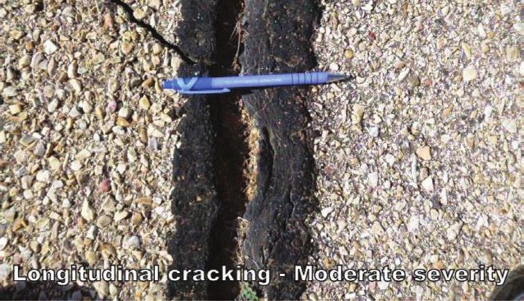
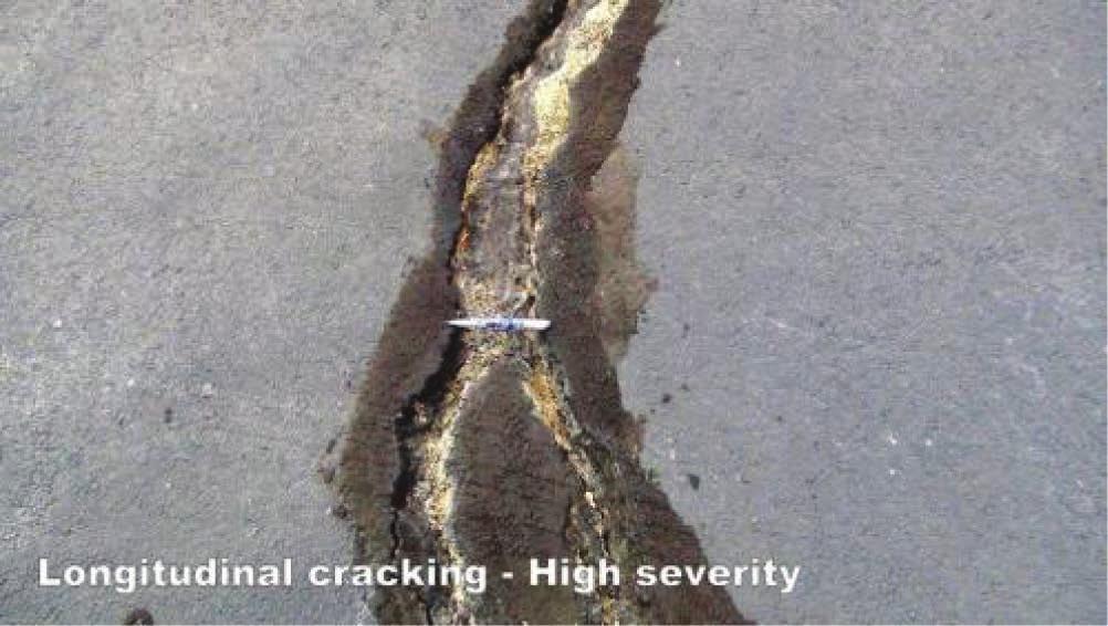
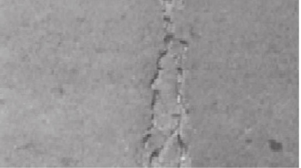
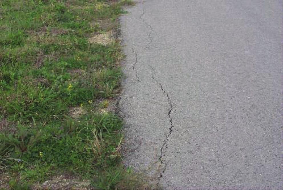
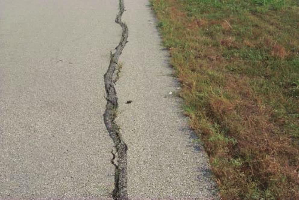
9 Longitudinal/Transverse/Edge Cracking (Non-PCC Joint Reflective) Description Longitudinal cracks are parallel to the pavement s center line or laydown direction. They may be caused by (1) a poorly constructed paving lane joint, (2) shrinkage of the asphalt concrete (AC) surface due to low temperatures or hardening of the asphalt, or (3) a reflective crack caused by cracks beneath the surface course, including cracks in PCC slabs (but not at PCC joints). These types of cracks are not usually load associated. If the pavement is fragmented along a crack, the crack is said to be spalled. Transverse cracks extend across the pavement at approximately right angles to the pavement s center line or direction of laydown. They may be caused by (1) a poorly constructed paving lane joint, (2) shrinkage of the AC surface due to low temperatures or hardening of the asphalt, or (3) a reflective crack caused by cracks beneath the surface course, including cracks in PCC slabs (but not at PCC joints). These types of cracks are not usually load associated. If the pavement is fragmented along a crack, the crack is said to be spalled. Edge cracking is differentiated from longitudinal cracking only in the location of the cracks. Edge cracks occur within 4 ft of the edge. All severities are the same. Edge cracks are often treated differently than cracks in the middle of the pavement and are listed separately for this reason. Step 3. Identify Distress Types 9
10 Step 3. Identify Distress Types 10 Severity Levels Low Medium High One of the following conditions exists: (1) cracks are moderately spalled (some FOD potential) and can be either filled or non-filled of any width; (2) filled cracks are not spalled or are lightly spalled, but filler is in unsatisfactory condition; (3) non-filled cracks are not spalled or are only lightly spalled, but the mean crack width is greater than ¼ in. (6 mm), or (4) light random cracking exists near the crack or at the corners of intersecting cracks. Cracks have only light spalling (little or no FOD potential) or no spalling, and can be filled or nonfilled. If non-filled, the cracks have a mean width of ¼ in. (6 mm) or less; filled cracks are of any width, but their filler material is in satisfactory condition. Cracks are severely spalled and pieces are loose or missing, causing definite FOD potential. Cracks can be either filled or nonfilled of any width.


11 Low Few Cracks Longitudinal, Few Cracks Medium High Many Cracks Step 3. Identify Distress Types 11


12 Step 3. Identify Distress Types Low Transverse Cracks, 20 or 50 Ft Apart Medium High Low Edge Cracks Medium High 12
13 Joint Reflection Cracking from PCC (Longitudinal and Transverse) Description This distress occurs only on pavements having an asphalt or tar surface over a PCC slab. This category does not include reflection cracking from any other type of base (that is, cement stabilized, lime stabilized). Such cracks are listed as longitudinal and transverse cracks. Joint reflection cracking is caused mainly by movement of the PCC slab beneath the AC surface because of thermal and moisture changes; it is not load related. However, traffic loading may cause a breakdown of the AC near the crack, resulting in spalling and FOD potential. If the pavement is fragmented along a crack, the crack is said to be spalled. Knowledge of slab dimensions beneath the AC surface will help to identify these cracks. Severity Levels Low Medium High One of the following conditions exists: cracks are moderately spalled (some FOD potential) and can be either filled or non-filled of any width; filled cracks are not spalled or are lightly spalled but filler is in unsatisfactory condition; non-filled cracks are not spalled or are only lightly spalled, but the mean crack width is greater than ¼ in. (6 mm); or light random cracking exists near the crack or at the corners of intersecting cracks. Cracks have only light spalling (little or no FOD potential) or no spalling and can be filled or nonfilled. If non-filled, the cracks have a mean width of ¼ in. (6 mm) or less; filled cracks are of any width, but their filler material is in satisfactory condition. Cracks are severely spalled with pieces loose or missing causing definite FOD potential. Cracks can be either filled or non-filled of any width. Step 3. Identify Distress Types 13


14 Step 3. Identify Distress Types 14 Joint Reflection Cracking from PCC (Longitudinal and Transverse) Low Medium High
15 Block Cracking Description Block cracks are interconnected cracks that divide the pavement into approximately rectangular pieces. The blocks may range in size from approximately 1 ft by 1 ft to 10 ft by 10 ft (0.3 m by 0.3 m to 3 m by 3 m). Block cracking is caused mainly by shrinkage of the AC and daily temperature cycling (that results in daily stress/strain cycling). It is not load associated. The occurrence of block cracking usually indicates that the asphalt has hardened significantly. Block cracking normally occurs over a large portion of pavement area but sometimes will occur only in non-traffic areas. This type of distress differs from alligator cracking in that the alligator cracks form smaller, many-sided pieces with sharp angles. Also unlike block cracks, alligator cracks are caused by repeated traffic loadings and are, therefore, located only in traffic areas (that is, wheel paths). Severity Levels Low Medium High Blocks are defined by either filled or non-filled cracks that are moderately spalled (some FOD potential); non-filled cracks that are not spalled or have only minor spalling (some FOD potential) but have a mean width greater than approximately ¼ in. (6 mm); or filled cracks of greater than ¼ in. that are not spalled or have only minor spalling (some FOD potential) but have filler in unsatisfactory condition. Blocks are defined by cracks that are non-spalled (sides of the crack are vertical) or lightly spalled, causing no FOD potential. Non-filled cracks have ¼ in. (6 mm) or less mean width, and filled cracks have filler in satisfactory condition. Blocks are well defined by cracks that are severely spalled, causing a definite FOD potential. Step 3. Identify Distress Types 15


16 Step 3. Identify Distress Types 16 Block Crack Low Medium High
17 Alligator or Fatigue Cracking Description Alligator or fatigue cracking is a series of interconnecting cracks caused by fatigue failure of the AC surface under repeated traffic loading. The cracking initiates at the bottom of the AC surface (or stabilized base) where tensile stress and strain are highest under a wheel load. The cracks propagate to the surface initially as a series of parallel cracks. After repeated traffic loading, the cracks connect, forming many-sided, sharp-angled pieces that develop a pattern resembling chicken wire or the skin of an alligator. The pieces are less than 2 ft (0.6 m) on the longest side. Alligator cracking occurs only in areas that are subjected to repeated traffic loadings, such as wheel paths. Therefore, it would not occur over an entire area unless the entire area was subjected to traffic loading. (Pattern-type cracking that occurs over an entire area that is not subjected to loading is rated as block cracking, that is, not a load-associated distress.) Alligator cracking is considered a major structural distress. Severity Levels Low Medium High Further development of light alligator cracking into a pattern or network of cracks that may be lightly spalled. Medium-severity alligator cracking is defined by a well-defined pattern of interconnecting cracks, where all pieces are securely held in place (good aggregate interlock between pieces). Fine, longitudinal hairline cracks running parallel to one another with none or only a few interconnecting cracks. The cracks are not spalled. Network or pattern cracking has progressed so that the pieces are well defined and spalled at the edges; some of the pieces rock under traffic and may cause FOD potential. Step 3. Identify Distress Types 17


18 Step 3. Identify Distress Types 18 Alligator or Fatigue Cracking (10% or 30%) Low Medium High
19 Surface Distress There are four types of surface distress usually found on airport pavements. Weathering (Surface Wear) Dense Mix Asphalt Description The wearing away of the asphalt binder and fine aggregate matrix from the pavement surface. Severity Levels For this tool, the pavement should be identified as either low severity (starting to weather) or high severity (definitely weathering). Low Medium High Loss of fine aggregate matrix is noticeable, and edges of coarse aggregate have been exposed up to ¼ width (of the longest side) of the coarse aggregate due to the loss of fine aggregate matrix. Asphalt surface beginning to show signs of aging, which may be accelerated by climatic conditions. Loss of the fine aggregate matrix is noticeable and may be accompanied by fading of the asphalt color. Edges of the coarse aggregates are beginning to be exposed (less than 1 mm or 0.05 in.). Pavement may be relatively new (as new as 6 months old). Edges of coarse aggregate have been exposed greater than ¼ width (of the longest side) of the coarse aggregate. There is considerable loss of fine aggregate matrix, leading to potential or some loss of coarse aggregate. Step 3. Identify Distress Types 19


20 Step 3. Identify Distress Types Low Weathering (Surface Wear) High 20
21 Raveling Description Raveling is the dislodging of coarse aggregate particles from the pavement surface. Dense Mix Severity Levels As used herein, coarse aggregate refers to predominant coarse aggregate sizes of the asphalt mix. Aggregate clusters refer to when more than one adjoining coarse aggregate piece is missing. If in doubt about a severity level, three representative areas of 1 yd 2 each (1 m 2 ) should be examined and the number of missing coarse aggregate particles counted. Severity Levels Slurry Seal/Coal Tar over Dense Mix Low Medium High (1) In a yd 2 (m 2 ) representative area, the number of coarse aggregate particles missing is between 21 and 40, and/or (2) missing aggregate clusters are between 2% and 10% of the examined yd 2 (m 2 ) area. In medium-severity raveling, there is some FOD potential. significant FOD potential. (1) In a yd 2 (m 2 ) representative area, the number of coarse aggregate particles missing is between 5 and 20, and/or (2) missing aggregate clusters are less than 2% of the examined yd 2 (m 2 ) area. In low-severity raveling, there is little or no FOD potential. (1) The scaled area is less than 1%. (2) In the case of coal tar where pattern cracking has developed, the surface cracks are less than ¼ in. (6 mm) wide. (1) The scaled area is between 1% and 10%. (2) In the case of coal tar where pattern cracking has developed, the cracks are ¼ in. (6 mm) wide or greater. (1) In a yd 2 (m 2 ) representative area, the number of coarse aggregate particles missing is over 40, and/or (2) missing aggregate clusters are more than 10% of the examined yd 2 (m 2 ) area. In highseverity raveling, there is (1) The scaled area is over 10%. (2) In the case of coal tar, the surface is peeling off. Step 3. Identify Distress Types 21


22 Step 3. Identify Distress Types Low Raveling High 22


23 Patching Description A patch is considered a defect, no matter how well it is performing. Severity Levels Low Medium High Patch is somewhat deteriorated and affects ride quality to some extent. Moderate amount of distress is present within the patch or has FOD potential, or both. Patch is in good condition and is performing satisfactorily. Patch is badly deteriorated and affects ride quality significantly or has high FOD potential. Patch soon needs replacement. Patching (10% or 30% Slabs) Low Medium High Step 3. Identify Distress Types 23
24 Step 3. Identify Distress Types 24 Roughness Roughness, as used in this tool, is a combination of several distress types, which are corrugation, depression, and swell. Regardless of the distress type, select the category that best matches the impact of the distress. Corrugation Corrugation is a series of closely spaced ridges and valleys (ripples) occurring at fairly regular intervals (usually less than 5 ft) (1.5 m) along the pavement. The ridges are perpendicular to the traffic direction. Traffic action combined with an unstable pavement surface or base usually causes this type of distress. Severity Runways and High- Speed Taxiways L <¼ in. (6 mm) <½ in. (13 mm) Taxiways and Aprons M ¼ to ½ in. (6 to 13 mm) ½ to 1 in. (13 to 25 mm) H >½ in. (13 mm) >1 in. (25 mm) Corrugations are minor and do not significantly affect ride quality.
25 Depression Depressions are localized pavement surface areas having elevations slightly lower than those of the surrounding pavement. In many instances, light depressions are not noticeable until after a rain, when ponding water creates birdbath areas; but the depressions can also be located without rain because of stains created by ponding of water. Depressions can be caused by settlement of the foundation soil or can be built during construction. Depressions cause roughness and, when filled with water of sufficient depth, could cause hydroplaning of aircraft. L M H Maximum Depth of Depression Runways and High-Speed Taxiways to ½ in. (3 to 13 mm) ½ to 1 in. (13 to 25 mm) >1 in. (>25 mm) Taxiways and Aprons ½ to 1 in. (13 to 25 mm) 1 to 2 in. (25 to 51 mm) >2 in. (>51 mm) Severity Levels The depression can be observed or located by stained areas, only slightly affects pavement riding quality, and may cause hydroplaning potential on runways (see measurement criteria). The depression can be observed, moderately affects pavement riding quality, and causes hydroplaning potential on runways (see measurement criteria). The depression can be readily observed, severely affects pavement riding quality, and causes definite hydroplaning potential (see measurement criteria). Step 3. Identify Distress Types 25
26 Step 3. Identify Distress Types 26 Swell Swell is characterized by an upward bulge in the pavement s surface. A swell may occur sharply over a small area or as a longer, gradual wave. Either type of swell can be accompanied by surface cracking. A swell is usually caused by frost action in the subgrade or by swelling soil, but a small swell can also occur on the surface of an asphalt overlay (over PCC) as a result of a blowup in the PCC slab. Severity Height Differential Severity Levels L M <¾ in. (20 mm) Swell is barely visible and has a minor effect on the pavement s ride quality. (Lowseverity swells may not always be observable, but their existence can be confirmed by driving a vehicle over the section. An upward acceleration will occur if the swell is present.) ¾ to 1½ in. (20 to 40 mm) Swell can be observed without difficulty and has a significant effect on the pavement s ride quality. H >1½ in. (40 mm) Swell can be readily observed and severely affects the pavement s ride quality.


27 Rate severity on high-speed taxiways using measurement criteria provided above. Double the height differential criteria for other taxiways and aprons. Step 3. Identify Distress Types 27
28 Step 3. Identify Distress Types 28 For each area of analysis, select the combinations of distress type, extent, and severity found in that area: Distress Type and Extent Severity Few longitudinal cracks or joints Low severity Medium severity High severity Many longitudinal cracks Low severity Medium severity High severity A few edge cracks Low severity Medium severity High severity Transverse cracks 50 ft apart Low severity Medium severity High severity Transverse cracks 20 ft apart Low severity Medium severity High severity Block cracking Low severity Medium severity High severity Reflection cracking Low severity Medium severity High severity Fatigue cracking: 10% of area Low severity Medium severity High severity Fatigue cracking: 30% Low severity Medium severity High severity Starting to weather Low severity Definitely weathering Medium severity Starting to ravel Low severity Definitely raveling Medium severity Patching: 10% of area Low severity Medium severity High severity Patching: 30% of area Low severity Medium severity High severity Roughness Long wavelength swells Many long wavelength Many short swells wavelength bumps
29 Distresses Joint Problems Page Cracking Page Surface Distress Page Joint Seal Damage 30 Longitudinal, Transverse, and Diagonal Cracks (Mid-panel 37 Patching 44 cracking) Spalling 33 Corner Break 40 Settlement or Faulting 46 Joint Problems Shattered Slab/Intersecting Cracks 42 There are two types of joint problems usually found on airport pavements. Step 3. Identify Distress Types 29
30 Step 3. Identify Distress Types 30 Joint Seal Damage Description Joint seal damage is any condition that enables soil or rocks to accumulate in the joints or allows significant infiltration of water. Accumulation of incompressible materials prevents the slabs from expanding and may result in buckling, shattering, or spalling. A pliable joint filler bonded to the edges of the slabs protects the joints from accumulation of materials and also prevents water from seeping down and softening the foundation supporting the slab. Typical types of joint seal damage are (1) stripping of joint sealant, (2) extrusion of joint sealant, (3) weed growth, (4) hardening of the filler (oxidation), (5) loss of bond to the slab edges, and (6) lack or absence of sealant in the joint.
31 Severity Levels Low Medium High Joint sealer is in generally fair condition over the entire surveyed sample, with one or more of the above types of damage occurring to a moderate degree. Sealant needs replacement within 2 years. Joint seal damage is at medium severity if a few of the joints have any of the following conditions: (1) joint sealer is in place but water access is possible through visible openings no more than 1 8 in. (3 mm) wide; if a knife blade cannot be inserted easily between sealer and joint face, this condition does not exist; (2) pumping debris are evident at the joint; (3) joint sealer is oxidized and lifeless but pliable (like a rope) and generally fills the joint opening; or (4) vegetation in the joint is obvious but does not obscure the joint opening. Joint sealer is in generally good condition throughout the sample. Sealant is performing well with only a minor amount of any of the above types of damage present. Joint seal damage is at low severity if a few of the joints have sealer that has debonded from, but is still in contact with, the joint edge. This condition exists if a knife blade can be inserted between sealer and joint face without resistance. Joint sealer is in generally poor condition over the entire surveyed sample, with one or more of the above types of damage occurring to a severe degree. Sealant needs immediate replacement. Joint seal damage is at high severity if 10% or more of the joint sealer exceeds limiting criteria listed above or if 10% or more of sealer is missing. Step 3. Identify Distress Types 31


32 Step 3. Identify Distress Types 32 Joint Seal Damage Low Medium High
33 Spalling For the purposes of this tool, the two types of spalling (transverse/longitudinal joint and corner) are combined. Transverse and Longitudinal Joint Joint spalling is the breakdown of the slab edges within 2 ft (0.6 m) of the side of the joint. A joint spall usually does not extend vertically through the slab but intersects the joint at an angle. Spalling results from excessive stresses at the joint or crack caused by infiltration of incompressible materials or traffic load. Weak concrete at the joint (caused by overworking) combined with traffic loads is another cause of spalling. Note: Frayed condition as used in this test method indicates material is no longer in place along a joint or crack. Spalling indicates material may or may not be missing along a joint or crack. Step 3. Identify Distress Types 33
34 Step 3. Identify Distress Types 34 Low Medium High Spall over 2 ft (0.6 m) long: (1) spall is broken into more than three pieces defined by light or medium cracks; (2) spall is broken into no more than three pieces, with one or more of the cracks being severe with some FOD potential existing; or (3) joint is moderately frayed with some FOD potential. Spall less than 2 ft long: spall is broken into pieces or fragmented, with some of the pieces loose or absent, causing considerable FOD or tire damage potential. Moderately frayed means the upper edge of the joint is broken away, leaving a spall wider than 1 in. (25 mm) or deeper than ½ in. (13 mm). The material is mostly missing, with some FOD potential. Spall over 2 ft (0.6 m) long: (1) spall is broken into no more than three pieces defined by low- or medium-severity cracks; little or no FOD potential exists; or (2) joint is lightly frayed; little or no FOD potential. Spall less than 2 ft long is broken into pieces or fragmented with little FOD or tire damage potential exists. Lightly frayed means the upper edge of the joint is broken away leaving a spall no wider than 1 in. (25 mm) and no deeper than ½ in. (13 mm). The material is missing, and the joint creates little or no FOD potential. Note: If less than 2 ft (0.6 m) of the joint is lightly frayed, the spall should not be counted. Spall over 2 ft (0.6 m) long: (1) spall is broken into more than three pieces defined by one or more high-severity cracks with high FOD potential and high possibility of the pieces becoming dislodged, or (2) joint is severely frayed with high FOD potential.
35 Corner Corner spalling is the raveling or breakdown of the slab within approximately 2 ft (0.6 m) of the corner. A corner spall differs from a corner break in that the spall usually angles downward to intersect the joint, while a break extends vertically through the slab. Low Medium High One of the following conditions exists: (1) spall is broken into two or more pieces defined by medium-severity crack(s), and a few small fragments may be absent or loose; (2) spall is defined by one severe, fragmented crack that may be accompanied by a few hairline cracks; or, (3) spall has deteriorated to the point where loose material is causing some FOD potential. One of the following conditions exists: (1) spall is broken into one or two pieces defined by lowseverity cracks (little or no FOD potential); or (2) spall is defined by one medium-severity crack (little or no FOD potential). One of the following conditions exists: (1) spall is broken into two or more pieces defined by high-severity fragmented crack(s) with loose or absent fragments; (2) pieces of the spall have been displaced to the extent that a tire damage hazard exists; or (3) spall has deteriorated to the point where loose material is causing high FOD potential. A corner spall smaller than 3 in. (76 mm) wide (measured from the edge of the slab) and filled with sealant is not recorded. Step 3. Identify Distress Types 35


")
36 Step 3. Identify Distress Types 36 Spalling (Corner) Low Medium High
37 Cracking There are three types of cracking usually found on airport pavements. Longitudinal, Transverse, and Diagonal Cracks (Mid-Panel Cracking) Description These cracks, which divide the slab into two or three pieces, are usually caused by a combination of load repetition, curling stresses, and shrinkage stresses (for slabs divided into four or more pieces). Low-severity cracks are usually warping- or friction-related and are not considered major structural distresses. Medium- or high-severity cracks are usually working cracks and are considered major structural distresses. Note: Hairline cracks that are only a few feet long and do not extend across the entire slab are rated as shrinkage cracks. Step 3. Identify Distress Types 37
38 Step 3. Identify Distress Types 38 Severity Levels Low Medium High One of the following conditions exists: (1) filled or non-filled crack is moderately spalled (some FOD potential); (2) a non-filled crack has a mean width of between ⅛ and 1 in. (3 and 25 mm); (3) a filled crack is not spalled or only lightly spalled, but the filler is in unsatisfactory condition; or (4) the slab is divided into three pieces by two or more cracks, one of which is at least of medium severity. Crack has little or minor spalling (no FOD potential). If non-filled, it has a mean width of less than approximately ⅛ in. (3 mm). A filled crack can be of any width, but the filler material must be in satisfactory condition, or the slab is divided into three pieces by low-severity cracks. One of the following conditions exists: (1) filled or non-filled crack is severely spalled, causing definite FOD potential; (2) a nonfilled crack has a mean width of greater than approximately 1 in. (25 mm), creating a tire damage potential; or (3) the slab is divided into three pieces by two or more cracks, one of which is at least of high severity.


39 Longitudinal, Transverse, and Diagonal (Mid-Panel Cracking, 20% or 40% Slabs) Low Medium High Step 3. Identify Distress Types 39
40 Step 3. Identify Distress Types 40 Corner Break Description A corner break is a crack that intersects the joints at a distance of less than or equal to one-half of the slab length on both sides, measured from the corner of the slab. For example, a slab with dimensions of 25 ft by 25 ft (7.5 m by 7.5 m) that has a crack intersecting the joint 5 ft (1.5 m) from the corner on one side and 17 ft (5 m) on the other side is not considered a corner break; it is a diagonal crack. However, a crack that intersects 7 ft (2 m) on one side and 10 ft (3 m) on the other is considered a corner break. A corner break differs from a corner spall in that the crack extends vertically through the entire slab thickness, while a corner spall intersects the joint at an angle. Load repetition combined with loss of support and curling stresses usually cause corner breaks. Severity Levels Low Medium High One of the following conditions exists: (1) filled or non-filled crack is moderately spalled (some FOD potential); (2) a non-filled crack has a mean width of between ⅛ and 1 in. (3 and 25 mm); (3) a filled crack is not spalled or only lightly spalled, but the filler is in unsatisfactory condition; or (4) the area between the corner break and the joints is lightly cracked. Lightly cracked means one low-severity crack dividing the corner into two pieces. Crack has little or minor spalling (no FOD potential). If non-filled, it has a mean width less than approximately ⅛ in. (3 mm). A filled crack can be of any width, but the filler material must be in satisfactory condition. The area between the corner break and the joints is not cracked. One of the following conditions exists: (1) filled or non-filled crack is severely spalled, causing definite FOD potential; (2) a nonfilled crack has a mean width of greater than approximately 1 in. (25 mm), creating a tire damage potential; or (3) the area between the corner break and the joints is severely cracked.


41 Corner Break (10% or 30% Slabs) Low Medium High Step 3. Identify Distress Types 41
42 Step 3. Identify Distress Types 42 Shattered Slab/Intersecting Cracks Description Intersecting cracks are cracks that break the slab into four or more pieces due to overloading, inadequate support, or both. The high-severity level of this distress type, as defined as follows, is referred to as shattered slab. If all pieces or cracks are contained within a corner break, the distress is categorized as a severe corner break. Severity Levels Low Medium High Slab is broken into four or five pieces with over 15% of the cracks of medium severity (no high-severity cracks); slab is broken into six or more pieces with over 85% of the cracks of low severity. Slab is broken into four or five pieces predominantly defined by low-severity cracks. At this level of severity, the slab is called shattered: (1) slab is broken into four or five pieces with some or all cracks of high severity; or (2) slab is broken into six or more pieces with over 15% of the cracks of medium or high severity.

 Low")

43 Shattered Slab/Intersecting Cracks (10% or 30% Slabs) Low Medium High Step 3. Identify Distress Types 43
44 Step 3. Identify Distress Types 44 Surface Distress There are two types of surface distress usually found on airport pavements. Patching Description A patch is an area where the original pavement has been removed and replaced by a filler material. For condition evaluation, patching is divided into two types: small (less than 5 ft 2 [0.5 m 2 ]) and large (over 5 ft 2 ). Large patches are described in the next section. Severity Levels Low Medium High Patch deterioration or moderate spalling, or both, can be seen around the edges. Patch material can be dislodged with considerable effort, causing some FOD potential. Patch is functioning well with very little or no deterioration. Patch has deteriorated to a state that causes considerable roughness or high FOD potential, or both. The extent of the deterioration warrants replacement of the patch.


45 Patching (30% or 50% Slabs) Low Medium High Step 3. Identify Distress Types 45
46 Step 3. Identify Distress Types 46 Settlement or Faulting Description Settlement or faulting is a difference of elevation at a joint or crack caused by upheaval or consolidation. Severity Levels Severity levels are defined by the difference in elevation across the fault and the associated decrease in ride quality and safety as severity increases: Runways/Taxiways L <¼ in. (6 mm) M ¼ to ½ in. (6 to 13 mm) H >½ in. (13 mm) Aprons 1/8 to ½ in. (3 to 13 mm) ½ to 1 in. (13 to 25 mm) >1 in. (25 mm)


47 Settlement or Faulting (10% or 30% Slabs) Low Medium High Step 3. Identify Distress Types 47
48 Step 3. Identify Distress Types 48 For each area of analysis, select the combinations of distress type, extent, and severity found in that area: Distress Type and Extent Severity Joint seal damage None Low severity Medium severity High severity Joint and corner spalls Low severity Medium severity High severity Mid-panel cracks, 20% of slabs Low severity Medium severity High severity Mid-panel cracks, 40% of slabs Low severity Medium severity High severity Corner breaks, 10% of slabs Low severity Medium severity High severity Corner breaks, 30% of slabs Low severity Medium severity High severity Shattered slabs, 10% of slabs Low severity Medium severity High severity Shattered slabs, 30% of slabs Low severity Medium severity High severity Patches, 30% of slabs Low severity Medium severity High severity Patches, 50% of slabs Low severity Medium severity High severity Faulting, 10% of slabs Low severity Medium severity High severity Faulting, 30% of slabs Low severity Medium severity High severity
49 Step 4. Determine Treatment Using either asphalt or concrete pavement treatment tables, and previously identified airport classification, climatic zone, distress type extent severity, select the appropriate recommended and acceptable treatment. For all treatments except sealing and patching, it is recommended that a professional engineering firm with airport experience be engaged. Example: Airport Classification: Local Climatic Zone: Dry freeze Pavement Type: Concrete Distress Type: Corner breaks, 30% of slabs, medium severity = Recommended: full-depth repair (local) Acceptable: crack/joint seal If there are additional distress types, repeat Step 4. For each distress combination, select the preferred treatment. A facility might select the acceptable treatment instead of the recommended treatment for many reasons, such as local contractors, availability of material, the time to complete the treatment, and initial cost. Once the chosen treatment for each distress combination has been identified, the asphalt or concrete pavement treatment hierarchy table is consulted to determine whether a single treatment or multiple treatments should be performed. For example, if one combination suggested a fog seal and the other combination suggested an overlay, only the overlay would be performed. However, if the second combination suggested a crack seal, both would be performed. Step 4. Determine Treatment 49
50 50 Basic Asphalt Wet Freeze: Cracking Few long cracks, low severity Do nothing Crack seal/fill Few long cracks, med severity Do nothing Crack seal/fill Few long cracks, high severity Crack seal/fill Patch/recon area Many long cracks, low severity Do nothing, or AC overlay/mill + overlay Crack seal/fill Many long cracks, med severity Patch/reconstruct area or do nothing Crack seal/fill Many long cracks, high severity AC overlay/mill + overlay Patch/recon area Trans crack, 50 ft apart, low severity Do nothing Crack seal/fill Trans crack, 50 ft apart, med severity AC overlay/mill + overlay or do nothing Crack seal/fill Trans crack, 50 ft apart, high severity Crack seal/fill Patch/recon area Trans crack, 20 ft apart, low severity Do nothing Crack seal/fill Trans crack, 20 ft apart, med severity AC overlay/mill + overlay or do nothing Crack seal/fill Trans crack, 20 ft apart, high severity Crack seal/fill Asphalt overlay/mill + overlay Block crack, low severity Do nothing Crack seal/fill Block crack, med severity Do nothing Crack seal/fill Block crack, high severity Chip/cape seal AC overlay/mill + overlay
51 Basic Asphalt Wet Freeze: Cracking Few edge cracks, low severity Crack seal/fill Do nothing Few edge cracks, med severity AC overlay/mill + overlay or patch/recon area Crack seal/fill Few edge cracks, high severity AC overlay/mill + overlay Patch/recon area Reflection crack, low severity Do nothing Crack seal/fill Reflection crack, med severity AC overlay/mill + overlay or do nothing Crack seal/fill Reflection crack, high severity AC overlay/mill + overlay or rehab/recon Patch/recon area Fatigue crack, 10%, low severity Do nothing Crack seal/fill Fatigue crack, 10%, med severity Fog/coal tar seal Patch/recon area Fatigue crack, 10%, high severity AC overlay/mill + overlay Patch/recon area Fatigue crack, 30%, low severity Fog/coal tar seal AC overlay/mill + overlay or rehab/recon Fatigue crack, 30%, med severity Patch/reconstruct area or rehab/recon AC overlay/mill + overlay Fatigue crack, 30%, high severity AC overlay/mill + overlay or patch/recon area Rehab/recon 51
52 52 Basic Asphalt Wet Freeze: Surface Distress Start to weather Fog/coal tar seal, rejuvenator Do nothing Definitely weather Do nothing Fog/coal tar seal, rejuvenator Starting to ravel Fog/coal tar seal, rejuvenator Chip/cape seal Definitely ravel Chip/cape seal AC overlay/mill + overlay Patch, 10%, low severity Slurry/micro Do nothing Patch, 10%, med severity Do nothing Slurry/micro or patch/recon area Patch, 10%, high severity Patch/recon area AC overlay/mill + overlay Patch, 30%, low severity Fog/coal tar seal Do nothing Patch, 30%, med severity Fog/coal tar seal Patch/recon area Patch, 30%, high severity Patch/recon area AC overlay/mill + overlay Rough, long wave swell Patch/recon area Do nothing Rough, many long wave swells Patch/recon area AC overlay/mill + overlay Rough, many short wave bumps Patch/recon area AC overlay/mill + overlay
53 Basic Asphalt Wet No Freeze: Cracking Few long cracks, low severity Do nothing or rejuvenator Crack seal/fill Few long cracks, med severity Do nothing or rejuvenator Crack seal/fill Few long cracks, high severity AC overlay/mill + overlay Patch/recon area Many long cracks, low severity Do nothing Crack seal/fill Many long cracks, med severity AC overlay/mill + overlay Crack seal/fill Many long cracks, high severity Crack seal/fill AC overlay/mill + overlay Trans crack, 50 ft apart, low severity Do nothing Crack seal/fill Trans crack, 50 ft apart, med severity Do nothing Crack seal/fill Trans crack, 50 ft apart, high severity AC overlay/mill + overlay Crack seal/fill Trans crack, 20 ft apart, low severity Do nothing Crack seal/fill Trans crack, 20 ft apart, med severity Chip/cape seal Crack seal/fill Trans crack, 20 ft apart, high severity AC overlay/mill + overlay Crack seal/fill Block crack, low severity Do nothing Crack seal/fill Block crack, med severity AC overlay/mill + overlay Crack seal/fill Block crack, high severity Chip/cape seal AC overlay/mill + overlay 53
54 54 Basic Asphalt Wet No Freeze: Cracking Few edge cracks, low severity Crack seal/fill Do nothing Few edge cracks, med severity Rejuvenator Crack seal/fill Few edge cracks, high severity Crack seal/fill or rejuvenator Patch/recon area Reflection crack, low severity Do nothing Crack seal/fill Reflection crack, med severity Crack seal/fill Crack seal/fill Reflection crack, high severity Rehab/recon Patch/recon area Fatigue crack, 10%, low severity Patch/recon area Crack seal/fill Fatigue crack, 10%, med severity Chip/cape seal Crack seal/fill Fatigue crack, 10%, high severity Chip/cape seal Patch/recon area Fatigue crack, 30%, low severity Rejuvenator AC overlay/mill + overlay Fatigue crack, 30%, med severity Patch/recon area AC overlay/mill + overlay Fatigue crack, 30%, high severity AC overlay/mill + overlay Rehab/recon
55 Basic Asphalt Wet No Freeze: Surface Distress Start to weather Do nothing or rejuvenator Fog/coal tar seal Definitely weather Rejuvenator or fog/coal tar seal Slurry/micro Starting to ravel Slurry/micro Rejuvenator Definitely ravel Chip/cape seal AC overlay/mill + overlay Patch, 10%, low severity Do nothing Do nothing Patch, 10%, med severity Fog/coal tar seal Do nothing Patch, 10%, high severity Slurry/micro or chip/cape seal Patch/recon area Patch, 30%, low severity Crack seal/fill Do nothing Patch, 30%, med severity Chip/cape seal AC overlay/mill + overlay Patch, 30%, high severity Rehab/recon AC overlay/mill + overlay Rough, long wave swell Patch/recon area Do nothing Rough, many long wave swells Patch/recon area AC overlay/mill + overlay Rough, many short wave bumps Patch/recon area AC overlay/mill + overlay 55
56 56 Basic Asphalt Dry Freeze: Cracking Few long cracks, low severity Do nothing Crack seal/fill Few long cracks, med severity Crack seal/fill Crack seal/fill Few long cracks, high severity Crack seal/fill Patch/recon area Many long cracks, low severity Do nothing Crack seal/fill Many long cracks, med severity Crack seal/fill Crack seal/fill Many long cracks, high severity Patch/recon area AC overlay/mill + overlay Trans crack, 50 ft apart, low severity Do nothing Crack seal/fill Trans crack, 50 ft apart, med severity Do nothing Crack seal/fill Trans crack, 50 ft apart, high severity AC overlay/mill + overlay Crack seal/fill Trans crack, 20 ft apart, low severity Do nothing Crack seal/fill Trans crack, 20 ft apart, med severity Chip/cape seal Crack seal/fill Trans crack, 20 ft apart, high severity Chip/cape seal AC overlay/mill + overlay Block crack, low severity Do nothing Crack seal/fill Block crack, med severity Chip/cape seal Crack seal/fill Block crack, high severity Chip/cape seal AC overlay/mill + overlay
57 Basic Asphalt Dry Freeze: Cracking Few edge cracks, low severity Do nothing Crack seal/fill Few edge cracks, med severity Crack seal/fill Crack seal/fill Few edge cracks, high severity Crack seal/fill Patch/recon area Reflection crack, low severity Do nothing Crack seal/fill Reflection crack, med severity Crack seal/fill Crack seal/fill Reflection crack, high severity Crack seal/fill or rehab/recon Patch/recon area Fatigue crack, 10%, low severity Rejuvenator Crack seal/fill Fatigue crack, 10%, med severity Chip/cape seal Patch/recon area Fatigue crack, 10%, high severity AC overlay/mill + overlay Patch/recon area Fatigue crack, 30%, low severity Chip/cape seal AC overlay/mill + overlay Fatigue crack, 30%, med severity Chip/cape seal Patch/recon area Fatigue crack, 30%, high severity AC overlay/mill + overlay Patch/recon area 57
58 58 Basic Asphalt Dry Freeze: Surface Distress Start to weather Fog/coal tar seal Rejuvenator Definitely weather Fog/coal tar seal Slurry/micro Starting to ravel Slurry/micro Chip/cape seal Definitely ravel Slurry/micro Chip/cape seal Patch, 10%, low severity Crack seal/fill Do nothing Patch, 10%, med severity Slurry/micro or fog/coal tar seal Do nothing Patch, 10%, high severity Slurry/micro or fog/coal tar seal Patch/recon area Patch, 30%, low severity Crack seal/fill Do nothing Patch, 30%, med severity Patch/recon area AC overlay/mill + overlay Patch, 30%, high severity Patch/recon area AC overlay/mill + overlay Rough, long wave swell Patch/recon area Do nothing Rough, many long wave swells AC overlay/mill + overlay Do nothing Rough, many short wave bumps AC overlay/mill + overlay Do nothing
59 Basic Asphalt Dry No Freeze: Cracking Few long cracks, low severity Crack seal/fill Do nothing Few long cracks, med severity Do nothing Crack seal/fill Few long cracks, high severity Crack seal/fill Patch/recon area Many long cracks, low severity Crack seal/fill Do nothing Many long cracks, med severity Do nothing Crack seal/fill Many long cracks, high severity Crack seal/fill AC overlay/mill + overlay Trans crack, 50 ft apart, low severity Crack seal/fill Do nothing Trans crack, 50 ft apart, med severity Do nothing Crack seal/fill Trans crack, 50 ft apart, high severity Patch/recon area Crack seal/fill Trans crack, 20 ft apart, low severity Do nothing Crack seal/fill Trans crack, 20 ft apart, med severity Do nothing Crack seal/fill Trans crack, 20 ft apart, high severity Chip/cape seal Crack seal/fill Block crack, low severity Crack seal/fill Do nothing Block crack, med severity Do nothing Crack seal/fill Block crack, high severity Crack seal/fill AC overlay/mill + overlay 59
60 60 Basic Asphalt Dry No Freeze: Cracking Few edge cracks, low severity Crack seal/fill Do nothing Few edge cracks, med severity Do nothing Crack seal/fill Few edge cracks, high severity Crack seal/fill Patch/recon area Reflection crack, low severity Crack seal/fill Do nothing Reflection crack, med severity Do nothing Crack seal/fill Reflection crack, high severity Crack seal/fill Patch/recon area Fatigue crack, 10%, low severity Do nothing Crack seal/fill Fatigue crack, 10%, med severity Crack seal/fill Patch/recon area Fatigue crack, 10%, high severity AC overlay/mill + overlay Patch/recon area Fatigue crack, 30%, low severity Rejuvenator AC overlay/mill + overlay Fatigue crack, 30%, med severity AC overlay/mill + overlay Patch/recon area Fatigue crack, 30%, high severity Patch/recon area Rehab/recon
61 Basic Asphalt Dry No Freeze: Surface Distress Start to weather Fog/coal tar seal Rejuvenator Definitely weather Rejuvenator Fog/coal tar seal Starting to ravel Fog/coal tar seal Slurry/micro Definitely ravel Slurry/micro Chip/cape seal Patch, 10%, low severity Crack seal/fill Do nothing Patch, 10%, med severity Do nothing Crack seal/fill Patch, 10%, high severity AC overlay/mill + overlay Patch/recon area Patch, 30%, low severity Crack seal/fill Do nothing Patch, 30%, med severity AC overlay/mill + overlay Chip/cape seal or slurry/micro Patch, 30%, high severity Chip/cape seal or slurry/micro AC overlay/mill + overlay Rough, long wave swell Patch/recon area Do nothing Rough, many long wave swells AC overlay/mill + overlay Do nothing Rough, many short wave bumps AC overlay/mill + overlay Do nothing 61
62 62 Local Asphalt Wet Freeze: Cracking Few long cracks, low severity Do nothing Crack seal/fill Few long cracks, med severity Crack seal/fill Crack seal/fill Few long cracks, high severity Crack seal/fill Patch/recon area Many long cracks, low severity Rejuvenator or fog/coal tar seal Crack seal/fill Many long cracks, med severity AC Overlay/mill + overlay Crack seal/fill Many long cracks, high severity Rehab/recon AC overlay/mill + overlay Trans crack, 50 ft apart, low severity Do nothing Crack seal/fill Trans crack, 50 ft apart, med severity Crack seal/fill Crack seal/fill Trans crack, 50 ft apart, high severity Patch/recon area AC overlay/mill + overlay Trans crack, 20 ft apart, low severity Do nothing Crack seal/fill Trans crack, 20 ft apart, med severity Crack seal/fill AC overlay/mill + overlay Trans crack, 20 ft apart, high severity Chip/cape seal AC overlay/mill + overlay Block crack, low severity Rejuvenator Crack seal/fill Block crack, med severity AC overlay/mill + overlay Crack seal/fill Block crack, high severity Rehab/recon AC overlay/mill + overlay
63 Local Asphalt Wet Freeze: Cracking Few edge cracks, low severity Do nothing Crack seal/fill Few edge cracks, med severity Patch/recon area Crack seal/fill Few edge cracks, high severity Crack seal/fill Patch/recon area Reflection crack, low severity Do nothing Crack seal/fill Reflection crack, med severity Crack seal/fill Crack seal/fill Reflection crack, high severity Rehab/recon Patch/recon area Fatigue crack, 10%, low severity Do nothing Crack seal/fill Fatigue crack, 10%, med severity Crack seal/fill Patch/recon area Fatigue crack, 10%, high severity AC overlay/mill + overlay Patch/recon area Fatigue crack, 30%, low severity Rehab/recon AC overlay/mill + overlay Fatigue crack, 30%, med severity Rehab/recon AC overlay/mill + overlay Fatigue crack, 30%, high severity AC overlay/mill + overlay Rehab/recon 63
FLORIDA DEPARTMENT OF TRANSPORTATION
 FLORIDA DEPARTMENT OF TRANSPORTATION FLEXIBLE PAVEMENT CONDITION SURVEY HANDBOOK March 2012 STATE MATERIALS OFFICE Table of Contents Title Page List of Tables... i List of Figures... ii Executive Summary...
2017 Pavement Management Services Pavement Condition Report Salt Lake City, UT
 2017 Pavement Management Services Pavement Condition Report Salt Lake City, UT Prepared by: Data Transfer Solutions, LLC 3680 Avalon Park East Blvd., Suite 200 Orlando, FL 32828 www.dtsgis.com Table of
Driving Indiana s Economic Growth
 Driving Indiana s Economic Growth IRI/PCR/RUT Field Verification Kumar P. Dave Manager, Road & Pavement Asset Management & Programming, INDOT 03-06-2012 Organization Chart Pavement Division, INDOT David
AERODROME ADVISORY CIRCULAR
 GOVERNMENT OF INDIA OFFICE OF DIRECTOR GENERAL OF CIVIL AVIATION AD AC NO. 2 of 2017 5 th July 2017 AERODROME ADVISORY CIRCULAR Subject: Guidance on Movement Area Pavement Maintenance Procedures at Aerodromes.
Non-State Federal Aid Highways. Pavement Condition Ratings. H e r k i m e r a n d O n e i d a C o u n t i e s
 Non-State Federal Aid Highways Pavement Condition Ratings 2010 H e r k i m e r a n d O n e i d a C o u n t i e s 2010 PAVEMENT CONDITION RATINGS for the Non-State Federal Aid Highway System in Herkimer
Pavement and Asset Management from a City s Perspective Mike Rief, PE, DBIA and Andrea Azary, EIT. February 12, 2015
 Pavement and Asset Management from a City s Perspective Mike Rief, PE, DBIA and Andrea Azary, EIT February 12, 2015 What is Pavement Management? At a Network Level: Pavement management refers to a systematic
Airfield Pavement Smoothness Airport Pavement Workshop. Michael Gerardi APR Consultants
 Airfield Pavement Smoothness Airport Pavement Workshop Michael Gerardi APR Consultants Presentation Overview Why is Smoothness Important New Pavement Acceptance Criteria - (FAA AC 150/5370) 16-Foot Straightedge
VDOT s Pavement Management Program. Presented by: Tanveer Chowdhury Maintenance Division, VDOT March 05, 2010
 VDOT s Pavement Management Program Presented by: Tanveer Chowdhury Maintenance Division, VDOT March 05, 2010 Outline Pavement Management network and project level Pavement Data Collection and QA/QC Data
Introduction to Full Depth Asphalt Repairs. Setting Work Processes for a Quality Job Start in time to finish prior to Winter!
 Introduction to Full Depth Asphalt Repairs Setting Work Processes for a Quality Job Start in time to finish prior to Winter! Asphalt Pothole and Patching Repairs Smaller Repairs! Where do Potholes come
Appendix B Existing ADOT Data Parameters
 Appendix B Existing ADOT Data Parameters Appendix 08/04/03 HPMS by Item Number All records 1 Year of Submittal 2 State Code 3 English or Metric Reporting Units 4 County Code 5 Section Identification (ID)
City of Davis Pavement Management Program
 City of Davis Pavement Management Program Davis Street and Bike Path System 163 centerline miles of streets (33 million square feet) 34.6 miles of arterials 21% 22.8 miles of collectors 14% 103.9 miles
Southeaster Pavement Preservation Partnership 2010 Update Welcome to Tennessee. Michael J. Doran, P.E. Maintenance Division
 Southeaster Pavement Preservation Partnership 2010 Update Welcome to Tennessee Michael J. Doran, P.E. Maintenance Division Why are we here today? The Solution Background Information Geographic Locations
Use of Performance Metrics on The Pennsylvania Turnpike. Pamela Hatalowich, Penn Turnpike Commission Paul Wilke, Applied Research Associates, Inc.
 Use of Performance Metrics on The Pennsylvania Turnpike Pamela Hatalowich, Penn Turnpike Commission Paul Wilke, Applied Research Associates, Inc. Presentation Outline Background- Turnpike Construction
For the purpose of a runway surface friction assessment the following definitions apply: Definition/Description
 ADVISORY CIRCULAR BURUNDI CIVIL AVIATION AUTHORITY CAA AC-AGA 0008 Date: October 2013 FRICTION TESTING AND MAINTENANCE OF PAVED RUNWAY SURFACES 1. PURPOSE This Advisory Circular provides guidance for testing
Performance of Ultra-Thin Bounded Wearing Course (UTBWC) Surface Treatment on US-169 Princeton, Minnesota. Transportation Research
 Surface Treatment on US-169 Princeton, Minnesota. Transportation Research") 2007-18 Performance of Ultra-Thin Bounded Wearing Course (UTBWC) Surface Treatment on US-169 Princeton, Minnesota Take the steps... Research...Knowledge...Innovative Solutions! Transportation Research
2007-18 Performance of Ultra-Thin Bounded Wearing Course (UTBWC) Surface Treatment on US-169 Princeton, Minnesota Take the steps... Research...Knowledge...Innovative Solutions! Transportation Research
Keeping good roads good
 Pavement Preservation (PP) in the State of California- Protecting Their Road and Street Investment R. Gary Hicks PhD, PE CP2 Center, Chico CA Prepared for the 3 rd International Pavement Maintenance Technology
Portland Peninsula Sidewalk and Ramp Inventory
 Portland Peninsula Sidewalk and Ramp Inventory Conducted June and July of 2008 By Anne Krikorian and Ryan Carmichael Performed under the authority of: Greater Portland Council of Governments And with the
Burns Cooley Dennis, Inc. Geotechnical and Materials Engineering Consultants Performance of Permeable Friction Courses NCHRP 9-41
 Burns Cooley Dennis, Inc. Geotechnical and Materials Engineering Consultants Performance of Permeable Friction Courses NCHRP 9-41 L. Allen Cooley, Jr. Presentation Outline Definition Benefits Maintenance
Executive Summary. Introduction
 Executive Summary Introduction The future of our local economy is uncertain, but one thing we know we must manage our infrastructure smarter. State and local agencies are facing challenging times. There
An Overview of Mn/DOT s Pavement Condition Rating Procedures and Indices (September 2015)
") An Overview of Mn/DOT s Pavement Condition Rating Procedures and Indices (September 2015) Equipment Mn/DOT currently collects pavement condition data using a Pathway Services, Inc. Digital Inspection Vehicle
An Overview of Mn/DOT s Pavement Condition Rating Procedures and Indices (September 2015) Equipment Mn/DOT currently collects pavement condition data using a Pathway Services, Inc. Digital Inspection Vehicle
Figure 2 Existing Track Condition: Concrete patches along track length. Grass/Weeds growing through numerous cracks. Page 1
 INTRODUCTION Located along the western coast of Kauai, the Mana Drag Racing Strip (MDRS) at the Kauai Raceway Park was originally constructed in 1971. This 40+ year old track, once home to taro fields
An Overview of Mn/DOT s Pavement Condition Rating Procedures and Indices (March 27, 2003)
") An Overview of Mn/DOT s Pavement Condition Rating Procedures and Indices (March 27, 2003) Equipment Mn/DOT currently collects pavement condition data using a Pathway Services, Inc. Video Inspection Vehicle
An Overview of Mn/DOT s Pavement Condition Rating Procedures and Indices (March 27, 2003) Equipment Mn/DOT currently collects pavement condition data using a Pathway Services, Inc. Video Inspection Vehicle
City of West Des Moines PAVEMENT MANAGEMENT SYSTEM
 City of West Des Moines PAVEMENT MANAGEMENT SYSTEM 12/11/2018 Municipal Street Seminar (11-14-2018) JEFF NASH 1 City Background Information: - West Des Moines current census Population is around 66,000
RAILWAY LEVEL CROSSING CHECKLIST Road Safety Review of Railway Crossings
 RAILWAY LEVEL CROSSING CHECKLIST Road Safety Review of Railway Crossings Location: Crossing No. Date of On-Site Inspection: (Day) / / (Night) / / Weather: CHECKLIST 5. - GENERAL TOPICS Level of control
MNDOT PAVEMENT DESIGN MANUAL
 MNDOT PAVEMENT DESIGN MANUAL Chapter 6 Ramps, Shoulders, Turn Lanes & Miscellaneous Pavements MnDOT Pavement Engineer Date Contents Introduction... 1 600 Ramps and Loops... 1 610 - Shoulders... 2 620 -
The Use and Performance of Geogrids in Kentucky
 Transportation Kentucky Transportation Center Research Report University of Kentucky Year 2003 The Use and Performance of Geogrids in Kentucky Aric Cowne Richard Reitenour David L. Allen R. Clark Graves
1. PURPOSE 3. DEFINITION OF TERMS. For the purpose of a runway surface friction assessment the following definitions apply: Definition/Description
 Page 1 of 15 1. PURPOSE The purpose of this Advisory Circular is to provide guidance for testing and measuring of friction characteristics of the runway, provision of maintenance measures to abraded surfacing
NCHRP Project 9-40 Update Optimization of Tack coat for HMA Placement
 NCHRP Project 9-40 Update Optimization of Tack coat for HMA Placement Louay N. Mohammad Louisiana Transportation Research Center Louisiana State University Emulsion: Design, Construction, and Performance
Tacoma Streets 101. City of Tacoma - Citizen Neighborhood Street Improvement and Safety Task Force
 1 Tacoma Streets 101 2 Streets Maintenance Overview Type and amount of streets Condition and types of construction Maintenance and repair methods and costs Sample Project Philosophy/Selection Criteria
Advantages & Specifications for the Use of Perma-Patch for the Repair of Potholes
 Advantages & Specifications for the Use of Perma-Patch for the Repair of Potholes The Pothole Solution... p.2 Specifications... p.3 Using Perma-Patch in Severe Weather... p.4 www.permapatch.com Frequently
ADOT Maintenance Data Collection Guide
 ADOT Maintenance Data Collection Guide January 1, 2009 Prepared for Arizona Department of Transportation Prepared by Jani Demaree and Cambridge Systematics, Inc. 100 CambridgePark Drive, Suite 400 ADOT
PENNDOT HPMS DATA COLLECTION GUIDE. Bureau of Planning and Research Transportation Planning Division April 2016 (Updated March 2018)
") PENNDOT HPMS DATA COLLECTION GUIDE Bureau of Planning and Research April 2016 (Updated March 2018) State Street Dauphin County NOTES INTRODUCTION The purpose of this document is to provide you with some
PENNDOT HPMS DATA COLLECTION GUIDE Bureau of Planning and Research April 2016 (Updated March 2018) State Street Dauphin County NOTES INTRODUCTION The purpose of this document is to provide you with some
MOUNTAIN FLYING TEST
 MOUNTAIN FLYING TEST USE ANSWER SHEET (AF FORM 1584C, EXAM RECORD) ON THE LAST PAGE OF THIS TEST. 1. It is best to plan an early morning flight to take advantage of the air, which is: a. hotter and smoother.
Pavement Management Program
 Pavement Management Program Public Works Department January 5, 2016 Chad Butzow, P.E. Deputy Director Field Operation Services Public Works Department Brian Martineau Pavement Manager Public Works Department
PENNDOT HPMS DATA COLLECTION GUIDE
 PENNDOT HPMS DATA COLLECTION GUIDE Bureau of Planning and Research April 2016 (Updated September 2017) State Street Dauphin County INTRODUCTION The purpose of this document is to provide you with some
Road Condition Statistics: Notes and definitions
 Road Condition Statistics: Notes and definitions This note provides definitions used for road condition statistics. It also includes useful information on the source of the data 1. Source The statistics
ONTARIO REGULATION 239/02 MUNICIPAL ACT MINIMUM MAINTENANCE STANDARDS FOR MUNICIPAL HIGHWAYS
 ONTARIO REGULATION 239/02 made under the MUNICIPAL ACT Made: July 23, 2002 Filed: August 8, 2002 MINIMUM MAINTENANCE STANDARDS FOR MUNICIPAL HIGHWAYS Definitions 1. (1) In this Regulation, cm means centimetres;
Cracking and Roughness of Asphalt Pavements Constructed Using Cement-Treated Base Materials
 Brigham Young University BYU ScholarsArchive All Theses and Dissertations 2006-03-20 Cracking and Roughness of Asphalt Pavements Constructed Using Cement-Treated Base Materials Jonathan Russell Hanson
Department of Internal Affairs Mandatory Non-Financial Performance Measures 2013 Roads and Footpaths
 Road Asset Technical Accord - RATA The Centre of Excellence for Road Asset Planning in the Waikato Region Department of Internal Affairs Mandatory Non-Financial Performance Measures 2013 Roads and Footpaths
BEST PRACTICE FOR COMPACTING WARM AND HOT MIX ASPHALT NEAUPG OCTOBER 7,2009
 BEST PRACTICE FOR COMPACTING WARM AND HOT MIX ASPHALT NEAUPG OCTOBER 7,2009 DAILY SAFETY-QUALITY- PRODUCTION EVERY PROJECT EVERY DAY EVERY TON 101 COST SAVING IDEAS FROM NAPA WARM MIX ASPHALT RAP STOCKPILE
6.7 Aircraft Protection
 Schedules to Decision 377 6.7 Aircraft Protection 6.7.1 Introduction This introduction is to assist the lay reader to understand how this sub-chapter works and what it applies to. It is not an aid to interpretation
Transportation Engineering
 Transportation Engineering For Civil Engineering By www.thegateacademy.com Syllabus Syllabus for Transportation Engineering Transportation Infrastructure: Highway Alignment and Engineering Surveys; Geometric
APPENDIX A TWO-LANE RURAL ROADS ELEMENTS OF DESIGN CREST VERTICAL CURVES
 APPENDIX A TWO-LANE RURAL ROADS ELEMENTS OF DESIGN CREST VERTICAL CURVES 1. Two-lane Rural Roads 1.1 Introduction The definition of rural area can be derived from the definition of urban areas. Officially,
Transportation Engineering II Dr. Rajat Rastogi Department of Civil Engineering Indian Institute of Technology - Roorkee
 Transportation Engineering II Dr. Rajat Rastogi Department of Civil Engineering Indian Institute of Technology - Roorkee Lecture 31 Runway Orientation Dear students, I welcome you back to the lecture series
Field guide for Accessible Public Rights-of-Way Edition
 Field guide for Accessible Public Rights-of-Way 2015 Edition BRIEFING MEMO SUBJECT: Department of Justice/Department of Transportation Joint Technical Assistance on Title II of the Americans with Disabilities
High Performance Racetracks
 High Performance Racetracks Good for a Racetrack, Good for a Highway? 38 th Annual Rocky Mountain Asphalt Conference and Equipment Show Brian D. Prowell, Ph.D., P.E. Road Courses Advanced Materials Services
FAIRWAY PALMS II CONDOMINIUM PROPERTY
 FAIRWAY PALMS II CONDOMINIUM PROPERTY 6533, through 6553 SE Federal HWY, Stuart Florida, 34997. Structural Inspection Report Prepared by CA 26583 Ph: 561-204-5000 Fax: 561-204-1050 E-mail: aali@universalengineering.net
SECTION 48 - TRAFFIC STRIPES AND PAVEMENT MARKINGS TABLE OF CONTENTS
 SECTION 48 - TRAFFIC STRIPES AND PAVEMENT MARKINGS TABLE OF CONTENTS Section Page 48-1 GENERAL... 48.1 48-2 THERMOPLASTIC TRAFFIC STRIPES AND PAVEMENT MARKINGS... 48.1 48-3 PAINTED TRAFFIC STRIPES AND
County of Sacramento Standard Construction Specifications January 1, 2008 TECHNICAL PROVISIONS
 County of Sacramento Standard Construction Specifications January 1, 2008 TECHNICAL PROVISIONS SECTION 48 TRAFFIC STRIPES AND PAVEMENT MARKINGS 48-1 GENERAL Traffic stripes and pavement markings shall
Access Management Standards
 Access Management Standards Section 1: Application of Access Standards This chapter describes the Department's access management standards for access connections on the county roadway system. The standards
Pavement Quality Indicators
 Pavement Quality Indicators Five Year Report (2009-2013) for The Nebraska Department of Roads Research Technician: Connor Villanueva Advisor: Prof Wayne Jensen 1. Report No SPR- P1 (13) 4. Title and Subtitle
APPENDIX I-A Kings County Regional Transportation Plan. Appendix A Page A-1 STATE ROUTES
 APPENDIX I-A STATE ROUTES Interstate 5 SR 33 SR 41 SR 43 SR 137 SR 198 SR 269 (See under City of Avenal) (See Figure 4-2 and 4-3 for Rural and Urban Functional Classifications) Appendix A Page A-1 INTERSTATE
Item 585 Ride Quality for Pavement Surfaces
 Item 585 Ride Quality for Pavement Surfaces 1. DESCRIPTION 2. EQUIPMENT Measure and evaluate the ride quality of pavement surfaces. 2.1. Surface Test Type A. Provide a 10-ft. straightedge or where allowed,
Rennick Yard Roller-Compacted Concrete Pavement
 RCC Pavement Council Rennick Yard Roller-Compacted Concrete Pavement February 12, 2016 Submitted By: NCE 1885 S. Arlington Ave., Suite 111 Reno, NV 89509 Phone: 775.329.4955 Site Plan and Pavement Sections
C ITY OF B EDFORD H EIGHTS
 C ITY OF B EDFORD H EIGHTS T ABLE OF C ONTENTS 1. Executive Summary... 2 2. Background... 3 3. PART I: 2016 Pavement Condition... 8 4. PART II: 2018 Current Backlog... 13 5. PART III: Maintenance &
SUPPORTING NOTES FOR THE EVALUATION OF UNBOUND ROAD BASE AND SUB-BASE AGGREGATES
 SUPPORTING NOTES FOR THE EVALUATION OF UNBOUND ROAD BASE AND SUB-BASE AGGREGATES (These notes are guidelines only and must not be included in the Contract Documents). 1. SCOPE These Notes are guidelines
State of Nevada Department of Transportation Materials Division
 State of Nevada Department of Transportation Materials Division METHOD OF TEST FOR EVALUATION OF PAVEMENT RIDE QUALITY USING INERTIAL PROFILING SYSTEMS SCOPE This test method describes the procedure used
Summary of Findings Concerning Longitudinal Cracking on 16' Wide Ramps
 Summary of Findings Concerning Longitudinal Cracking on 16' Wide Ramps Office of Pavement Engineering October 14, 2003 Abstract: This paper summarizes the current practice in ODOT regarding the construction
UNDERWATER BRIDGE INSPECTION REPORT STRUCTURE NO CSAH NO. 7 OVER THE SNAKE RIVER DISTRICT 1 - PINE COUNTY
 UNDERWATER BRIDGE INSPECTION REPORT STRUCTURE NO. 58506 CSAH NO. 7 OVER THE SNAKE RIVER DISTRICT 1 - PINE COUNTY PREPARED FOR THE MINNESOTA DEPARTMENT OF TRANSPORTATION BY COLLINS ENGINEERS, INC. JOB NO.
Avalanche Problem Essentials Wind Slabs. Development
 1 Avalanche Problem Essentials Wind Slabs This document is part of Decision Making in Avalanche Terrain: a fieldbook for winter backcountry users by Pascal Haegeli, Roger Atkins and Karl Klassen and provides
FACE CONSULTANTS LIMITED. Accelerated Abrasion Resistance Surveys. BS :2002 And BS : A2: 2011
 FACE CONSULTANTS LIMITED Accelerated Abrasion Resistance Surveys In accordance with BS 13892-4:2002 And BS 8204-2: 2003 + A2: 2011 Further explanatory information What is Abrasion Resistance? Abrasion
SECTION 48 - TRAFFIC STRIPES AND PAVEMENT MARKINGS TABLE OF CONTENTS
 SECTION 48 - TRAFFIC STRIPES AND PAVEMENT MARKINGS TABLE OF CONTENTS Section Page 48-1 GENERAL...48.1 48-2 THERMOPLASTIC TRAFFIC STRIPES AND PAVEMENT MARKINGS...48.1 48-3 PAINTED TRAFFIC STRIPES AND PAVEMENT
Downloaded from Downloaded from /1
 VI SEMESTER FINAL EXAMINATION-2003 Q. [1] [a] Draw a right angle four-arm intersection of two roads and show various conflicts points if [a] both roads are with way movements, and [b] one road is with
DRAFT WSDOT PAVEMENT POLICY
 DRAFT WSDOT PAVEMENT POLICY JANUARY 2010 Washington State Department of Transportation Environmental and Engineering Programs Division State Materials Laboratory Pavements Division P.O. Box 47365 Olympia,
RoaDrain Synthetic Subsurface Drainage Layer (SSDL)
") RoaDrain Synthetic Subsurface Drainage Layer (SSDL) INSTALLATION QUALITY ASSURANCE MANUAL Contents 1.0 INTRODUCTION... 1 2.0 ROLL PACKAGING... 1 3.0 MATERIAL DELIVERY... 1 4.0 UNLOADING & STORAGE PROCEDURES...
RoaDrain Synthetic Subsurface Drainage Layer (SSDL) INSTALLATION QUALITY ASSURANCE MANUAL Contents 1.0 INTRODUCTION... 1 2.0 ROLL PACKAGING... 1 3.0 MATERIAL DELIVERY... 1 4.0 UNLOADING & STORAGE PROCEDURES...
I-64 BATTLEFIELD BLVD: PERFORMANCE MEETS EXPECTATION
 I-64 BATTLEFIELD BLVD: PERFORMANCE MEETS EXPECTATION Affan Habib, P.E., Pavement Program Manager March 1, 2019 Presentation Outline 1. Introduction 2. Project Descriptions 3. Pavement Performance 4. Predicted
Driveway Design Criteria
 Design Manual Chapter 5 - Roadway Design 5L - Access Management 5L-4 Driveway Design Criteria A. General For efficient and safe operations, access drives and minor public street intersections can be improved
PAVEMENT AND ALIGNMENT DESIGN OF A NEW RURAL ROAD IN THE PROVINCE OF BOLOGNA
 Alma Mater Studiorum - Università di Bologna FACULTY OF ENGINEERING AND ARCHITECTURE International Master Course in Civil Engineering DICAM CIVIL ENGINEERING MASTER THESIS In Infrastructure Systems PAVEMENT
Pavement Evaluation of the Nairobi Eastern By-Pass Road
 International Journal of Scientific and Research Publications, Volume 8, Issue 11, November 2018 547 Pavement Evaluation of the Nairobi Eastern By-Pass Road T. M. Nyang au, S. K. Mwea & P.K. Matheri Department
Maintenance of Roads in Pakistan
 Maintenance of Roads in Pakistan NHA s Perspective BY Engr. Tabjeel Ashraf P.E., BSc. (Civil Engg), MSc (Civil Engg), MPM MPEC,MPMI, MIEP, MASCE Presented at Institution of Engineers Pakistan (IEP) Islamabad
Tour de Chip Seal. Tour de Chip Seal Follow- up Report and Conclusions May 16, 2013
 Tour de Chip Seal Follow- up Report and Conclusions May 16, 2013 Old Jackson Highway, Victor Idaho Tour de Chip Seal Teton County Idaho and Teton County Wyoming May 16, 2013 1. Old Jackson Highway, North
Calibration and Validation of the Shell Fatigue Model Using AC10 and AC14 Dense Graded Hot Mix Asphalt Fatigue Laboratory Data
 Article Calibration and Validation of the Shell Fatigue Model Using AC10 and AC14 Dense Graded Hot Mix Asphalt Fatigue Laboratory Data Mofreh Saleh University of Canterbury, Private Bag 4800, Christchurch,
TAO Safety Policy No. HS-5.1 Page 1 of 15 Revision No. 2 Revision Date: July 19, 2005
 TAO Safety Policy No. HS-5.1 Page 1 of 15 Revision No. 2 1.0 OVERVIEW This safety policy provides guidance for conducting trenching and excavation activities at project sites. Emphasis is placed on sloping
Pavement Management Report. City Council Meeting of May 21, 2013
 Pavement Management Report City Council Meeting of May 21, 2013 Previous Meetings Summary In February, we presented the 2012 pavement survey and our consultant presented general pavement management strategies
Case Studies Using Falling Weight Deflectometer Data with Mechanistic Empirical Design and Analysis
 Case Studies Using Falling Weight Deflectometer Data with Mechanistic Empirical Design and Analysis International Symposium on Pavement Performance Trends, Advances, and Challenges December 5, 2011, Tampa,
Kentucky s Surface Transportation System
 Kentucky s Surface Transportation System ROAD AND BRIDGE CONDITIONS, TRAFFIC SAFETY, TRAVEL TRENDS, AND NEEDS MARCH 2018 PREPARED BY WWW.TRIPNET.ORG Founded in 1971, TRIP of Washington, DC, is a nonprofit
ADA Training Standard Plans
 ADA Training Standard Plans SCREEN READABLE VERSION IS IN THE MAKING AND WILL BE MADE AVAILABLE SOON 2018 MnDOT 2 Standard Plans 2017 Overview Overview PROWAG and Curb Ramp Basics Curb Ramp Types ADA Curb
Design Overview. Section 4 Standard Plans for Design. Pedestrian Access Routes. Pedestrian Access Routes. Overview. Cross Slope
 Design Overview Section 4 Standard Plans for Design Fall, 2017 Ann Johnson, PE Services Brady Rutman, SRF Consulting Group Overview Design Basics Recommendations: The Zone System Driveway Crossings Pedestrian
Basket for Janice. by Beth Hester. GH Productions, Inc. The Basket Maker s Catalog
 Basket for Janice by Beth Hester GH Productions, Inc. The Basket Maker s Catalog Materials are available from your basketry supply store or contact: The Basket Maker s Catalog GH Productions, Inc. 521
SPECIFICATION FOR INSTALLATION OF RAISED PAVEMENT MARKERS. This specification shall apply to the installation of raised pavement markers.
 SPECIFICATION FOR INSTALLATION OF RAISED PAVEMENT MARKERS 1 SCOPE This specification shall apply to the installation of raised pavement markers. 2 DEFINITIONS Type A Marker - Retroreflective raised pavement
Section 3A.04 Colors. Section 3B.10 Approach Markings for Obstructions
 Section 3A.04 Colors Markings shall be yellow, white, red, or blue, or purple. The colors for markings shall conform to the standard highway colors. Black in conjunction with one of the above colors shall
Transportation Engineering - II Dr. Rajat Rastogi Department of Civil Engineering Indian Institute of Technology - Roorkee. Lecture - 35 Exit Taxiway
 Transportation Engineering - II Dr. Rajat Rastogi Department of Civil Engineering Indian Institute of Technology - Roorkee Lecture - 35 Exit Taxiway Dear students, we are back with the lecture series of
FIELD EVENTS DIAGRAMS
 FIELD EVENTS DIAGRAMS Landing System Approach HIGH JUMP The declination in the high jump approach shall not exceed 1:100 (1%). The approach shall consist of a semicircle or rectangle of unvarying surface.
WYDOT DESIGN GUIDES. Guide for. Non-NHS State Highways
 WYDOT DESIGN GUIDES Guide for Non-NHS State Highways 2014 GUIDE FOR Non-NATIONAL HIGHWAY SYSTEM (Non-NHS) STATE HIGHWAYS PRESERVATION REHABILITATION RECONSTRUCTION INTRODUCTION This Guide is directed to
ASPHALT PAVING LEVEL 1
 ASPHALT PAVING LEVEL 1 Module 3: Yield Calculations: Tack Coat and Mix Spread Rate FDOT Course Module 3 1 Welcome the students to the third module in this course that covers tack coat and mix spread rates,
Lake Waterford Community Association Meeting. November 15, 2016
 Lake Waterford Community Association Meeting November 15, 2016 Introduction Staff Introduction Project Overviews - Completed Projects - Pavement Management Program - Pasadena Road Sidewalk Improvements
ANNUAL INSPECTION BY A QUALIFIED PROFESSIONAL ENGINEER ALL CCR IMPOUNDMENTS CCR Rule Section (b)
") ANNUAL INSPECTION BY A QUALIFIED PROFESSIONAL ENGINEER ALL CCR IMPOUNDMENTS ASBURY POWER PLANT 21133 Uphill Lane Asbury, Missouri 64832 January 18, 2019 LIBERTY UTILITIES Empire District Prepared by: Rachel
ANNUAL INSPECTION BY A QUALIFIED PROFESSIONAL ENGINEER ALL CCR IMPOUNDMENTS ASBURY POWER PLANT 21133 Uphill Lane Asbury, Missouri 64832 January 18, 2019 LIBERTY UTILITIES Empire District Prepared by: Rachel
RULES PUBLICATION NO. 52/P UNDERWATER INSPECTION OF MOBILE OFFSHORE DRILLING UNITS IN LIEU OF DRYDOCKING
 RULES PUBLICATION NO. 52/P UNDERWATER INSPECTION OF MOBILE OFFSHORE DRILLING UNITS IN LIEU OF DRYDOCKING 2001 Publications P (Additional Rule Requirements) issued by Polski Rejestr Statków complete or
Managing Density For Asphalt Pavement
 Managing Density For Asphalt Pavement 1 Density vs. Pavement Performance 2 Cost of Compaction Least expensive part of the process Compaction adds little to the cost of a ton of asphalt Importance of Compaction
RAA Highway Assessment. Dukes Highway
 June 2013 Prepared By Ian Bishop Date 17 June 2013 Traffic Engineer T: 08 8202 4703 E: IBishop@raa.com.au Richard Butler Traffic & Road Safety Analyst T: 08 8202 4517 E: RButler2@raa.com.au Michael Jervis
Smoothing Out the Bumpy Road Ahead
 Julie Hannah, P.E. Technical Services and Asset Management May 11, 2017 Smoothing Out the Bumpy Road Ahead Nationwide D = Poor, At Risk Conditions & Capacity Pavement Condition & Congestion Nationwide
Pressure and Density Altitude
 Pressure and Density Altitude Reference Sources Pilot s Handbook of Aeronautical Knowledge o Pages 9-1 to 9-4, Aircraft Performance o Pages 9-20 to 9-21, Density Altitude Charts Study Questions 1. Where
UNDERWATER BRIDGE INSPECTION REPORT DISTRICT 4 - OTTER TAIL COUNTY
 UNDERWATER BRIDGE INSPECTION REPORT STRUCTURE NO. L0885 TWP NO. 970 OVER THE OTTER TAIL RIVER DISTRICT 4 - OTTER TAIL COUNTY PREPARED FOR THE MINNESOTA DEPARTMENT OF TRANSPORTATION BY COLLINS ENGINEERS,
Access requests to County streets and roadways are processed through one of the following methods:
 13.1 GENERAL APPLICATION PROCESS Access requests to County streets and roadways are processed through one of the following methods: A. Planned Developments may set general locations for access points.
UNDERWATER BRIDGE INSPECTION REPORT STRUCTURE NO CSAH 133 OVER A DITCH ST. LOUIS COUNTY
 UNDERWATER BRIDGE INSPECTION REPORT STRUCTURE NO. 7780 CSAH 133 OVER A DITCH ST. LOUIS COUNTY SEPTEMBER 27, 2012 PREPARED FOR THE MINNESOTA DEPARTMENT OF TRANSPORTATION BY COLLINS ENGINEERS, INC. JOB NO.
TYPES OF FOUNDATION. Superstructure. Substructure. Foundation
 TYPES OF FOUNDATION Introduction: The lowest artificially built part of a structure which transmits the load of the structure to the soil lying underneath is called foundation. The supporting part of a
Track Use and Maintenance Guidelines
 Precision Sports Surfaces, Inc. 3325 Lobban Place, Charlottesville, VA 22903 (434) 971-9628 Fax (434) 971-1131 www.precisionsurfaces.com Track Use and Maintenance Guidelines The following information is
ANNUAL INSPECTION BY A QUALIFIED PROFESSIONAL ENGINEER ALL CCR IMPOUNDMENTS CCR Rule Section (b)
") ANNUAL INSPECTION BY A QUALIFIED PROFESSIONAL ENGINEER ALL CCR IMPOUNDMENTS ASBURY POWER PLANT 21133 Uphill Lane Asbury, Missouri 64832 January 18, 2017 EMPIRE DISTRICT ELECTRIC COMPANY Prepared by: Rachel
ANNUAL INSPECTION BY A QUALIFIED PROFESSIONAL ENGINEER ALL CCR IMPOUNDMENTS ASBURY POWER PLANT 21133 Uphill Lane Asbury, Missouri 64832 January 18, 2017 EMPIRE DISTRICT ELECTRIC COMPANY Prepared by: Rachel
VISUAL AIDS FOR DENOTING OBSTACLES
 CHAPTER 6. VISUAL AIDS FOR DENOTING OBSTACLES 6.1 Objects to be marked and/or lighted Note. The marking and/or lighting of obstacles is intended to reduce hazards to aircraft by indicating the presence
Compaction Theory and Best Practices
 Compaction Theory and Best Practices 2017 Idaho Asphalt Conference Moscow Idaho October 26, 2017 Dave Johonson, P.E. Senior Regional Engineer Asphalt Institute Understanding the Importance of Density 1