PRELIMINARY STORM DRAINAGE REPORT
|
|
|
- Moses Barrett
- 5 years ago
- Views:
Transcription

1 PRELIMINARY STORM DRAINAGE REPORT DRURY LANE DEVELOPMENT 704 1ST STREET SULTAN, WA PARCEL # AUDITOR S FILE NO CITY OF SULTAN SNOHOMISH COUNTY, WASHINGTON PREPARED FOR: STACY MACGREGOR PO BOX 80 GOLD BAR, WA PREPARED BY: MICHAEL GIESEKE Date: January 5 th, 2018 RAIN CITY DEVELOPMENT DRURY LANE DEVELOPMENT PROJECT NO. RCD # NE 45 TH ST, SEATTLE, WA (425)
2 PRELIMINARY STORM DRAINAGE REPORT DRURY LANE DEVELOPMENT 704 1ST STREET SULTAN, WA PARCEL # AUDITOR S FILE NO CITY OF SULTAN SNOHOMISH COUNTY, WASHINGTON PREPARED FOR: STACY MACGREGOR PO BOX 80 GOLD BAR, WA PREPARED BY: MICHAEL GIESEKE Date: January 5 th, 2018 RAIN CITY DEVELOPMENT DRURY LANE DEVELOPMENT PROJECT NO. RCD # NE 45 TH ST, SEATTLE, WA (425)
3 Table of Contents 1) Project Overview:... 3 Analysis of Minimum Requirements:... 3 Minimum Requirement #1: Targeted Stormwater Site Plan... 3 Minimum Requirement #2: SWPPP Narrative:... 4 Minimum Requirements #3: Water Pollution Source Control for New Development:... 4 Minimum Requirements #4: Preservation of natural drainage systems and outfalls and provisions of off-site mitigation:... 4 Minimum Requirements #5: On-site Stormwater Management... 4 Minimum Requirements #6: Run-off Treatment Requirements... 5 Minimum Requirements #7: Flow control... 5 Minimum Requirements #8: Wetlands Protection... 5 Minimum Requirements #9: Operations and Maintenance Manual ) Vicinity Map: ) Existing Conditions Exhibits... 8 Assessor Map / SCOPI GIS... 8 USGS Soil Map... 9 Sensitive Area Map...10 FEMA...11 Existing Conditions Exhibit ) Existing Conditions Overview ) Areas of Site Limitation ) Off-Site Analysis...15 Targeted Drainage Report ) Drainage Design...17 Developed Conditions Exhibit ) SWPPP ) Permanent Stormwater Control Plan...20 Preliminary Conveyance Calculations:...20 Curve Number Calculation Exhibits...21 Manning s Pipe Sizing Equation Spreadsheets...21 Preliminary Infiltration Basin Calculations:...22 Preliminary Water Quality Calculations:...22 Preliminary Biofiltration Swale Calculations:...22 Preliminary Upstream Pre Treatmeant / Filtration Vault Calculations: ) Special Reports...23 Geotechnical Engineering Report...23 Environmental Study: ) Other Reports and Approvals ) Operations and Maintenance Manual ) Bond Quantity Worksheet...27 RCD # January, 2018 Drury Lane Development
4 1) Project Overview: The development name is the Drury Lane Development. The subject property address is 704 1st Street, in the City of Sultan, WA , PARCEL # , Auditor s File No The project consists of 1 existing parcel and 9-new parcels: One existing singlefamily residence will remain separate from the development within the existing parcel, 1 storm and recreation tract, and 8 new single-family residential lots will be constructed as part of the development. The stormwater from the existing property infiltrates onsite with overflows and groundwater leading to the existing stream west of the property. Other work will include a private roadway, driveways, a tight-lined conveyance system and an overall conveyance system. The project proposes to utilize the infiltrative nature of the existing soils and route the storm runoff to the existing low point onsite. The conveyance systems will route the stormwater runoff from the site for pre-treatment/water quality treatment upstream of the final stormwater permutation through an infiltration basin. Excess overflows will be routed to the existing city s stormwater conveyance system. Analysis of Minimum Requirements: Minimum Requirement #1: Targeted Stormwater Site Plan Drainage Plan Description: Once developed, runoff from the proposed new single family residences roof and footing drains, driveways, yards, and roadway will be collected and tight lined through a series of individual lot pipes systems conveyed to the roadway catch basin and storm pipes conveyance system that will convey the overall site flow to the proposed infiltration basin located in a proposed Storm Tract 999 on the southwest portion of the property. The infiltration basin will be sized per SCC 30.63A.550 so that discharges match the required range of pre-developed discharge rates. This will be accomplished by sizing the infiltration basin to fully infiltrate onsite. An emergency overflow system is proposed to tie into the existing City of Sultan Conveyance System. The WWHM 2012 Stormwater Program is used to size the stormwater system. Manning s equation and a backflow analysis will be used to size the onsite conveyance system. Proposed Water Quality Measures: Water quality treatment will be provided via storm-filter cartridges which will be located directly upstream of the infiltration basin. Existing and Proposed Drainage Basins: The project contains a single drainage basin onsite with existing stormwater infiltrating onsite. The storm runoff will be collected and treated prior to infiltration within the Storm Tract 999. The runoff in the existing condition spreads over the pervious surfaces as it sheet flows to the existing low point onsite and infiltrates. For further details, please see the Existing Conditions Exhibit located in Section 3 of this report, and the offsite analysis, in section 6 of this report. The runoff in the proposed conditions will drain from tight lined roof systems into the proposed closed conveyance systems consisting of standard catch basin and piped conveyance. The RCD # January, 2018 Drury Lane Development
5 runoff from the short plat is proposed to infiltrate onsite and be contained within the Storm Tract 999. Any overflows will be designed to spill into the existing City of Sultan roadway conveyance system. Proposed Drainage System: The proposed drainage system will consist of a series of catch basins, swales and ditches, storm pipes to collect and convey developed runoff to the water quality facilities andinfiltration basin onsite. The system will utilize water quality swale / pre-treatment basin / filtration vault facilities upstream of the infiltration system for water quality. Upstream Drainage Analysis: The project is bounded to the west by curb and gutter and adjacent properties on all other sides. Each adjacent property is graded to drain into the City of Sultan s roadway conveyance system with only minor shared area infiltrating onsite at the shared low point. There are small areas from adjacent lawns that drain to the onsite low point, but there are no significant upstream basin areas to the property and are assumed to have no contributions. Minimum Requirement #2: SWPPP Narrative: This will be completed following the Preliminary Plat Application. Element #1: Preserve Vegetation / Mark Clearing Limits: Element #2: Establish Construction Access: Element #3: Control Flow Rates: Element #4: Install Sediment Controls: Element #5: Stabilize Soils: Element #6: Protect Slopes: Element #7: Protect Permanent Drain Inlets: Element #8: Stabilize Channels and Outlets Element #9: Control Pollutants: Element #10: Control Dewatering: Element #11: Maintain BMP s: Element #12: Manage the Project: Minimum Requirements #3: Water Pollution Source Control for New Development: There are no identified source control activities that will need to be addressed as a part of this residential development. Minimum Requirements #4: Preservation of natural drainage systems and outfalls and provisions of off-site mitigation: The entire project site drains to the mid-site low point. The drainage onsite will be maintained so that runoff will continue to flow to the low point. Minimum Requirements #5: On-site Stormwater Management Stormwater management is required to be implemented in accordance with SCC 30.63A.525. The code states that BMP requirements are to be implemented to the maximum extent feasible without causing flooding or erosion impacts. The on-site gravelly and sandy soils are such that infiltration is feasible and recommended, per the geotechnical report, later contained within this cover. The on-site soils are classified as Hydrologic Soil Group A. Additionally, the project will RCD # January, 2018 Drury Lane Development
6 implement post-construction soil amendment and perforated stub-out connections to satisfy any additional LID requirements. Minimum Requirements #6: Run-off Treatment Requirements All on-site runoff will be treated using basic water quality measures. On-site water quality measures are proposed to be met with a pre-treatment basin or storm filter filtration facilities upstream of the infiltration basin. Please refer to Section 7 of this report for more details. Minimum Requirements #7: Flow control The proposed drainage system will consist of a series of catch basins and storm pipes to collect and convey the runoff to the infiltration basin on site and discharge any emergency overflows to the existing City of Sultan conveyance system. Please see the WWHM2012 calculations in Section 7 for infiltration basin sizing. Minimum Requirements #8: Wetlands Protection There are no wetlands located on site therefore no wetland protection is necessary for this project. Minimum Requirements #9: Operations and Maintenance Manual Operations and Maintenance manuals will be provided for the infiltration basin and water quality facilities in section 12 of this report. RCD # January, 2018 Drury Lane Development
7 Attachment B: Report summary: Drainage Information Summary Note: This section will be completed following preliminary plat submittal. RCD # January, 2018 Drury Lane Development
8 2) Vicinity Map: RCD # January, 2018 Drury Lane Development

9 3) Existing Conditions Exhibits Assessor Map / SCOPI GIS RCD # January, 2018 Drury Lane Development

10 USGS Soil Map RCD # January, 2018 Drury Lane Development

11 Sensitive Area Map Snohomish County Lidar Folio. FEMA Flood Plain Map available on the following page. RCD # January, 2018 Drury Lane Development
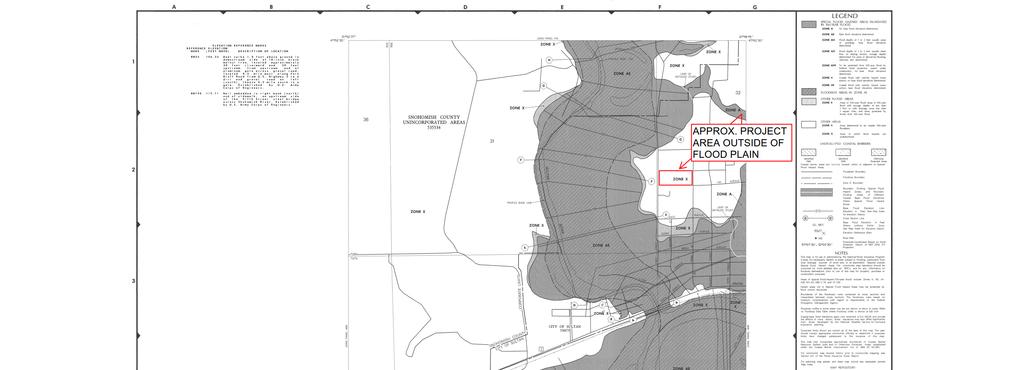
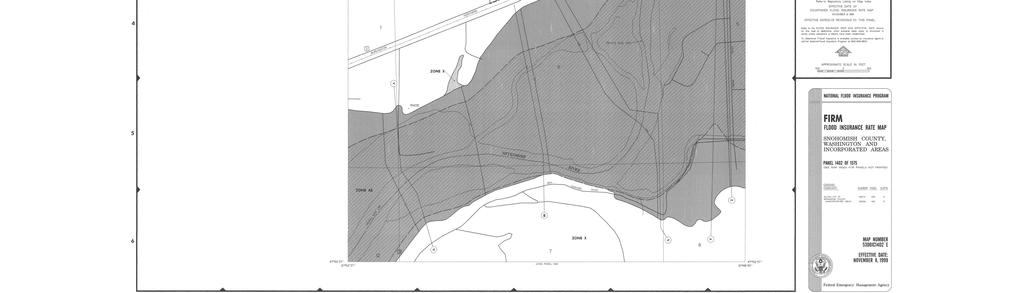
12
13
14 4) Existing Conditions Overview The subject property is rectangular east to west, is approximately 2.02 Acres (per Snohomish County Scopi). The property abuts 1 st Street, and is on the east side of the road. The frontage is approximately 180-ft north to south, and the property is approximately 490-ft east to west. There is an existing single-family resident on the southeast corner of the property. The property is mostly vegetation with a cluster of trees in the center portion of the property. Single family residences border the property on all sides except the western portion of the property which is accessed from 1 st Street. The project is generally level, with gentle slopes in towards the center third of the property with an approximate drop of 4-6 feet in the low spot from the general elevation of the subject property. Per the Snohomish County SnoScape (see geotechnical report in Section 10 of this report), there are no steep slopes onsite. Additionally, per the environmental review, there are no flood plains or wetlands on or adjacent to the site within 200-ft of the subject property. See special reports study, section 10 of this report for more information. Per the geotechnical report, the topsoil is loose organic sandy silt (top soil) and native mediumstiff non-plastic sandy silt (alluvium) extend to 3-4ft below the surface. Underlying these soils were medium-dense, gravelly sand and slightly silty sand (Alluvium) that generally extend to the maximum explored depth test pits. See the geotechnical report for more information, in Section 10 of this report. The topography of the site slopes to the low point in the middle-westerly portion of the site. The onsite vegetation is mostly second growth trees and vegetation. For drainage purposes, the site will be modeled as outwash-forest in its entirety. This project consists of one existing tax parcel with the following parcel number: The existing home will be partitioned into its own parcel separate from the developer as part of the residential project. RCD # January, 2018 Drury Lane Development
15 5) Areas of Site Limitation The site contains a low spot on the central-westerly portion of the site. This portion of the site will require special care during construction as to not compact the soils and adversely affect the permeability of the soils for future water quality and stormwater infiltration. Additionally this area will be required for in-situ onsite testing (PIT Test) to determine infiltration rates following the preliminary plat application submittal. RCD # January, 2018 Drury Lane Development
16 6) Off-Site Analysis The project abuts an existing City of Sultan stormwater conveyance system on High Street and 1st Street. The subject property does not drain off site and percolates into groundwater and infiltrates onsite combining with the City of Sultan stormwater conveyance system downstream. The subject property does not have any natural features in its downstream drainage path for any unforeseen flows that do overflow offsite. There are no known flooding issues within the subject property. The existing off-site conveyance system drains and outfalls to Skykomish River, more than a quarter-mile downstream of the site. A more in depth off-site analysis will be conducted following the preliminary plat review upon City requirement. Targeted Drainage Report The Targeted Drainage Report is included on the following page. RCD # January, 2018 Drury Lane Development
17 Targeted Drainage Report THIS PAGE INTENTIONALLY LEFT BLANK REPLACE PDF PAGE WITH TDR REPORT RCD # January, 2018 Drury Lane Development
18 7) Drainage Design The project consists of maintaining an existing single-family residence, a storm tract and 8 single-family residential detached dwelling units. This work includes a public road and will include minor frontage improvements and ROW dedication along 1st Street. Along with the frontage improvements, a storm drainage runoff collection system will be installed to capture runoff from the developed surfaces and conveyed to the onsite facilities for pre-treatment / water quality treatment and final dispersion through infiltration on site. Emergency overflow runoff will be designed to flow to the 1 st Street roadway containing the existing City of Sultan conveyance system. Please see the Developed Conditions Exhibit on the following page for more information. RCD # January, 2018 Drury Lane Development
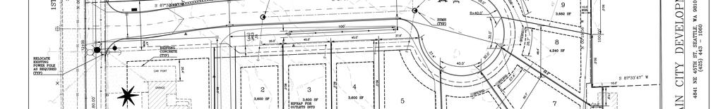
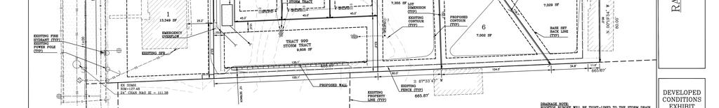
19
20 8) SWPPP The SWPPP will be prepared in accordance with the Snohomish County and Department of Ecology NPDES regulations and will be submitted separate from this report. Temporary Sediment Pond Sizing Calculations to be included in the final Storm Drainage Report. RCD # January, 2018 Drury Lane Development
21 9) Permanent Stormwater Control Plan Stormwater runoff will be collected by a combination of tight lined individual lot conveyance systems with LID perf-pipe/infiltration trenches with overflows into the project roadway conveyance system consisting of a series of catch basins and pipes. The roadway conveyance system will convey the stormwater runoff to a water quality swale / pretreatment basin / filtration facility upstream of the proposed infiltration facility. The stormwater runoff is proposed to fully infiltrate onsite. Any emergency overflow will be routed to the City of Sultan existing stormwater conveyance system off 1 st Street and High Street. Preliminary Conveyance Calculations: The onsite conveyance system will be sized using the rational method and Manning s formula sized for the 50-year storm event. The backwater conveyance calculations will be attached and exhibits provided following the preliminary plat application submittal. The preliminary sizing is provided on the following pages using basic pipe slope and manning equations for each conveyance system RCD # January, 2018 Drury Lane Development
22 Project Sultan 9 Lot Short Plat Date 9/4/2017 Description: Individual Lot - Roof and Footing Conveyance System C-Value (1-Lot, roof tightline conveyance) Type of Land Cover Dense Forest Light Forest Pasture Lawns Heavy Soil (Flat) Lawns Heavy Soil (Rolling) Playgrounds Gravel Areas Pavements and Roofs Open Water (pond, lakes, wetlands) Total C-Value Area IR - Peak Rainfall Intensity La Storm Event PR AR BR TC IR Total Precipitation Coefficient Coefficient Time of Concentration 25-year year Rational Method Storm Event C IR A QR 25-year year
23 Project Sultan 9 Lot Short Plat Date 9/4/2017 Description: Individual Lot - Yard Conveyance System Type of Land Cover Dense Forest Light Forest Pasture Lawns Heavy Soil (Flat) Lawns Heavy Soil (Rolling) Playgrounds Gravel Areas Pavements and Roofs C-Value (1-Lot, conveyance) Open Water (pond, lakes, wetlands) Total C-Value Area IR - Peak Rainfall Intensity Storm Event PR AR BR TC IR Total Precipitation Coefficient Coefficient Time of Concentration 25-year year Rational Method Storm Event C IR A QR 25-year year
24 Project Sultan 9 Lot Short Plat Date 9/4/2017 Description: 3-Lots - Yard Conveyance System Type of Land Cover Dense Forest Light Forest Pasture Lawns Heavy Soil (Flat) Lawns Heavy Soil (Rolling) Playgrounds Gravel Areas Pavements and Roofs C-Value (3-Lot conveyance) Open Water (pond, lakes, wetlands) Total C-Value Area IR - Peak Rainfall Intensity Storm Event PR AR BR TC IR Total Precipitation Coefficient Coefficient Time of Concentration 25-year year Rational Method Storm Event C IR A QR 25-year year
25 Project Sultan 9 Lot Short Plat Date 9/4/2017 Description: Roadway Conveyance System - Total basin area tributary to pond, not including storm tract Type of Land Cover Dense Forest Light Forest Pasture Lawns Heavy Soil (Flat) Lawns Heavy Soil (Rolling) Playgrounds Gravel Areas Pavements and Roofs C-Value (Roadway conveyance) Open Water (pond, lakes, wetlands) Total C-Value Area IR - Peak Rainfall Intensity Storm Event PR AR BR TC IR Total Precipitation Coefficient Coefficient Time of Concentration 25-year year Rational Method Storm Event C IR A QR 25-year year
26 Project Sultan 9 Lot Short Plat Date 9/4/2017 Description: Total Site Area Type of Land Cover Dense Forest Light Forest Pasture C-Value (Total Project Conveyance) Lawns Heavy Soil (Flat) Lawns Heavy Soil (Rolling) Playgrounds Gravel Areas Pavements and Roofs Open Water (pond, lakes, wetlands) Total C-Value Area IR - Peak Rainfall Intensity Storm Event PR AR BR TC IR Total Precipitation Coefficient Coefficient Time of Concentration 25-year year Rational Method Storm Event C IR A QR 25-year year
27
28
29
30
31
32
33
34 Preliminary Infiltration Basin Calculations: The project contains a single drainage basin onsite with existing stormwater infiltrating onsite. The runoff in the existing condition spreads over the pervious surfaces as it sheet flows to the existing low point onsite and infiltrates. For further details, please see the Existing Conditions Exhibit located in Section 3 of this report, and the offsite analysis, in section 6 of this report. The proposed infiltration basin is designed to accommodate all runoff from the proposed roadway, driveways, yards, roof and footing drains for the developed properties. The runoff will be collected and conveyed through a series of individual lot tightline conveyance systems to the roadway conveyance system consisting of catch basin and storm pipes to upstream water quality measures. Water quality treatment will be provided by a swale or filter-vault which will be located directly upstream of the infiltration basin. Further water quality measures can be found later in this section. Following the upstream water quality measures, the final infiltration basin will be located in the proposed Storm Tract 999 on the southwest portion of the property. The infiltration basin will be sized per SCC 30.63A.550 so that discharges match developed discharge durations to pre-developed durations for the range of pre-developed discharge rates from 50-percent of the two-year peak flow up to the full 50-year peak flow. The preliminary sizing has a target to infiltrate on flows onsite, with any unforeseen emergency overflows out letting to the City of Sultan existing conveyance system downstream of the project site. The WWHM 2012 Stormwater Program was used to size the stormwater basin. The WWHM calculations can be found at the end of this section. Preliminary Water Quality Calculations: All on-site PGIS runoff will be treated using basic water quality measures. Preliminary Biofiltration Swale Calculations: The preliminary water quality rates were calculated using the 15-min water-quality flow rate as determined upstream of the infiltration basin in Storm Tract 999. The Water Quality Flow rate was determined by WWHM to be cfs. Water quality will be treated with basic measures upstream of the infiltration basin with a pre-settling basin, vault or stormfilter cartridges or other means. Water quality measures will be finalized following the preliminary plat submittal. Preliminary Upstream Pre Treatmeant / Filtration Vault Calculations: If a filtration vault / oil water separator is allowed and / or required, it will be designed following the preliminary plat submittal. RCD # January, 2018 Drury Lane Development
35 WWHM2012 PROJECT REPORT Project Name: RCD S9L-FOS-3.0-Rock Site Name: Stacy MacGregor 9 Lot Short Plat Site Address: 1st Street City : Sultan Report Date: 12/11/2017 Gage : Everett Data Start : 1948/10/01 Data End : 2009/09/30 Precip Scale: 1.40 Version Date: 2017/04/14 Version : Low Flow Threshold for POC 1 : 50 Percent of the 2 Year High Flow Threshold for POC 1: 50 year PREDEVELOPED LAND USE Name : Basin 1 Bypass: No GroundWater: No Pervious Land Use acre A B, Forest, Flat Pervious Total Impervious Land Use acre Impervious Total 0 Basin Total Element Flows To: Surface Interflow Groundwater MITIGATED LAND USE Name : Lot 1 Bypass: No GroundWater: No
36 Pervious Land Use acre A B, Lawn, Flat.12 A B, Lawn, Mod.004 Pervious Total Impervious Land Use acre ROOF TOPS FLAT 0.1 DRIVEWAYS FLAT Impervious Total Basin Total Element Flows To: Surface Interflow Groundwater Bottom of Pond InfiltrBottom of Pond Infiltr Name : InfilTrnch 2 Bottom Length: ft. Bottom Width: 2.00 ft. Trench bottom slope 1: 0 To 1 Trench Left side slope 0: 0 To 1 Trench right side slope 2: 0 To 1 Material thickness of first layer: 3 Pour Space of material for first layer: 0.33 Material thickness of second layer: 1.5 Pour Space of material for second layer: 0.1 Material thickness of third layer: 0 Pour Space of material for third layer: 0 Discharge Structure Riser Height: 2.5 ft. Riser Diameter: 12 in. Element Flows To: Outlet 1 Outlet 2 Bottom of Pond Infiltr Gravel Trench Bed Hydraulic Table Stage(feet) Area(ac.) Volume(ac-ft.) Discharge(cfs) Infilt(cfs)
37
38 Name : Lot 2 Bypass: No GroundWater: No Pervious Land Use acre A B, Lawn, Flat.03 A B, Lawn, Mod.003 Pervious Total Impervious Land Use acre ROOF TOPS FLAT 0.04 DRIVEWAYS FLAT 0.01 Impervious Total 0.05 Basin Total Element Flows To: Surface Interflow Groundwater InfilTrnch 2 InfilTrnch 2 Name : Lot 3 Bypass: No
39 GroundWater: No Pervious Land Use acre A B, Lawn, Flat.03 A B, Lawn, Mod.003 Pervious Total Impervious Land Use acre ROOF TOPS FLAT 0.04 DRIVEWAYS FLAT 0.01 Impervious Total 0.05 Basin Total Element Flows To: Surface Interflow Groundwater InfilTrnch 3 InfilTrnch 3 Name : Lot 4 Bypass: No GroundWater: No Pervious Land Use acre A B, Lawn, Flat.03 A B, Lawn, Mod.003 Pervious Total Impervious Land Use acre ROOF TOPS FLAT 0.04 DRIVEWAYS FLAT 0.01 Impervious Total 0.05 Basin Total Element Flows To: Surface Interflow Groundwater InfilTrnch 4 InfilTrnch 4 Name : InfilTrnch 3 Bottom Length: ft. Bottom Width: 2.00 ft.
40 Trench bottom slope 1: 0 To 1 Trench Left side slope 0: 0 To 1 Trench right side slope 2: 0 To 1 Material thickness of first layer: 3 Pour Space of material for first layer: 0.33 Material thickness of second layer: 1.5 Pour Space of material for second layer: 0.1 Material thickness of third layer: 0 Pour Space of material for third layer: 0 Discharge Structure Riser Height: 2.5 ft. Riser Diameter: 12 in. Element Flows To: Outlet 1 Outlet 2 Bottom of Pond Infiltr Gravel Trench Bed Hydraulic Table Stage(feet) Area(ac.) Volume(ac-ft.) Discharge(cfs) Infilt(cfs)
41
42 Name : InfilTrnch 4 Bottom Length: ft. Bottom Width: 2.00 ft. Trench bottom slope 1: 0 To 1 Trench Left side slope 0: 0 To 1 Trench right side slope 2: 0 To 1 Material thickness of first layer: 3 Pour Space of material for first layer: 0.33 Material thickness of second layer: 1.5 Pour Space of material for second layer: 0.1 Material thickness of third layer: 0 Pour Space of material for third layer: 0 Discharge Structure Riser Height: 2.5 ft. Riser Diameter: 12 in. Element Flows To: Outlet 1 Outlet 2 Bottom of Pond Infiltr Gravel Trench Bed Hydraulic Table Stage(feet) Area(ac.) Volume(ac-ft.) Discharge(cfs) Infilt(cfs)
43
44 Name : Lot 5 Bypass: No GroundWater: No Pervious Land Use acre A B, Lawn, Flat.06 A B, Lawn, Mod.008 Pervious Total Impervious Land Use acre ROOF TOPS FLAT 0.08 DRIVEWAYS FLAT Impervious Total Basin Total Element Flows To: Surface Interflow Groundwater InfilTrnch 5 InfilTrnch 5 Name : InfilTrnch 5 Bottom Length: ft. Bottom Width: 2.00 ft. Trench bottom slope 1: 0 To 1 Trench Left side slope 0: 0 To 1 Trench right side slope 2: 0 To 1 Material thickness of first layer: 3 Pour Space of material for first layer: 0.33 Material thickness of second layer: 1.5 Pour Space of material for second layer: 0.1 Material thickness of third layer: 0 Pour Space of material for third layer: 0 Discharge Structure Riser Height: 2.5 ft. Riser Diameter: 12 in. Element Flows To: Outlet 1 Outlet 2 Bottom of Pond Infiltr Gravel Trench Bed Hydraulic Table
45 Stage(feet) Area(ac.) Volume(ac-ft.) Discharge(cfs) Infilt(cfs)
46 Name : Lot 6 Bypass: No GroundWater: No Pervious Land Use acre A B, Lawn, Flat.06 A B, Lawn, Mod.005 Pervious Total Impervious Land Use acre ROOF TOPS FLAT 0.08 DRIVEWAYS FLAT Impervious Total Basin Total 0.161
47 Element Flows To: Surface Interflow Groundwater InfilTrnch 6 InfilTrnch 6 Name : InfilTrnch 6 Bottom Length: ft. Bottom Width: 2.00 ft. Trench bottom slope 1: 0 To 1 Trench Left side slope 0: 0 To 1 Trench right side slope 2: 0 To 1 Material thickness of first layer: 3 Pour Space of material for first layer: 0.33 Material thickness of second layer: 1.5 Pour Space of material for second layer: 0.1 Material thickness of third layer: 0 Pour Space of material for third layer: 0 Discharge Structure Riser Height: 2.5 ft. Riser Diameter: 12 in. Element Flows To: Outlet 1 Outlet 2 Bottom of Pond Infiltr Gravel Trench Bed Hydraulic Table Stage(feet) Area(ac.) Volume(ac-ft.) Discharge(cfs) Infilt(cfs)
48
49 Name : Lot 7 Bypass: No GroundWater: No Pervious Land Use acre A B, Lawn, Flat.08 A B, Lawn, Mod.017 Pervious Total Impervious Land Use acre ROOF TOPS FLAT 0.06 DRIVEWAYS FLAT Impervious Total Basin Total Element Flows To: Surface Interflow Groundwater InfilTrnch 7 InfilTrnch 7 Name : InfilTrnch 7 Bottom Length: ft. Bottom Width: 2.00 ft. Trench bottom slope 1: 0 To 1 Trench Left side slope 0: 0 To 1 Trench right side slope 2: 0 To 1 Material thickness of first layer: 3 Pour Space of material for first layer: 0.33 Material thickness of second layer: 1.5 Pour Space of material for second layer: 0.1 Material thickness of third layer: 0 Pour Space of material for third layer: 0 Discharge Structure Riser Height: 2.5 ft. Riser Diameter: 12 in. Element Flows To:
50 Outlet 1 Outlet 2 InfilTrnch 6 Gravel Trench Bed Hydraulic Table Stage(feet) Area(ac.) Volume(ac-ft.) Discharge(cfs) Infilt(cfs)
51 Name : InfilTrnch 8 Bottom Length: ft. Bottom Width: 2.00 ft. Trench bottom slope 1: 0 To 1 Trench Left side slope 0: 0 To 1 Trench right side slope 2: 0 To 1 Material thickness of first layer: 3 Pour Space of material for first layer: 0.33 Material thickness of second layer: 1.5 Pour Space of material for second layer: 0.1 Material thickness of third layer: 0 Pour Space of material for third layer: 0 Discharge Structure
52 Riser Height: 2.5 ft. Riser Diameter: 12 in. Element Flows To: Outlet 1 Outlet 2 Bottom of Pond Infiltr Gravel Trench Bed Hydraulic Table Stage(feet) Area(ac.) Volume(ac-ft.) Discharge(cfs) Infilt(cfs)
53 Name : InfilTrnch 9 Bottom Length: ft. Bottom Width: 2.00 ft. Trench bottom slope 1: 0 To 1 Trench Left side slope 0: 0 To 1 Trench right side slope 2: 0 To 1 Material thickness of first layer: 3 Pour Space of material for first layer: 0.33 Material thickness of second layer: 1.5
54 Pour Space of material for second layer: 0.1 Material thickness of third layer: 0 Pour Space of material for third layer: 0 Discharge Structure Riser Height: 2.5 ft. Riser Diameter: 12 in. Element Flows To: Outlet 1 Outlet 2 InfilTrnch 8 Gravel Trench Bed Hydraulic Table Stage(feet) Area(ac.) Volume(ac-ft.) Discharge(cfs) Infilt(cfs)
55 Name : Lot 8 Bypass: No GroundWater: No
56 Pervious Land Use acre A B, Lawn, Flat.04 A B, Lawn, Mod.018 Pervious Total Impervious Land Use acre ROOF TOPS FLAT 0.03 DRIVEWAYS FLAT Impervious Total Basin Total Element Flows To: Surface Interflow Groundwater InfilTrnch 8 InfilTrnch 8 Name : Lot 9 Bypass: No GroundWater: No Pervious Land Use acre A B, Lawn, Flat.04 A B, Lawn, Mod.012 Pervious Total Impervious Land Use acre ROOF TOPS FLAT 0.03 DRIVEWAYS FLAT Impervious Total Basin Total Element Flows To: Surface Interflow Groundwater InfilTrnch 9 InfilTrnch 9 Name : ROW-US-Trench Bypass: No GroundWater: No Pervious Land Use acre
57 A B, Lawn, Flat.007 A B, Lawn, Mod.004 Pervious Total Impervious Land Use acre ROADS FLAT 0.15 Impervious Total 0.15 Basin Total Element Flows To: Surface Interflow Groundwater Bottom of Pond InfiltrBottom of Pond Infiltr Name : Storm Tract Bypass: No GroundWater: No Pervious Land Use acre A B, Lawn, Flat.12 A B, Lawn, Mod.005 Pervious Total Impervious Land Use acre DRIVEWAYS MOD 0.07 POND 0.03 Impervious Total 0.1 Basin Total Element Flows To: Surface Interflow Groundwater Bottom of Pond InfiltrBottom of Pond Infiltr Name : ROW-DS-Trenc Bypass: No GroundWater: No Pervious Land Use acre A B, Lawn, Flat.007 A B, Lawn, Mod.003
58 Pervious Total 0.01 Impervious Land Use acre ROADS FLAT Impervious Total Basin Total Element Flows To: Surface Interflow Groundwater Bottom of Pond InfiltrBottom of Pond Infiltr Name : Bottom of Pond Infiltration Gallery Bottom Length: ft. Bottom Width: ft. Trench bottom slope 1: 0 To 1 Trench Left side slope 0: 0 To 1 Trench right side slope 2: 0 To 1 Material thickness of first layer: 4 Pour Space of material for first layer: 0.33 Material thickness of second layer: 0 Pour Space of material for second layer: 0 Material thickness of third layer: 0 Pour Space of material for third layer: 0 Infiltration On Infiltration rate: 12 Infiltration safety factor: Total Volume Infiltrated (ac-ft.): Total Volume Through Riser (ac-ft.): Total Volume Through Facility (ac-ft.): Percent Infiltrated: 100 Total Precip Applied to Facility: 0 Total Evap From Facility: Discharge Structure Riser Height: 3.5 ft. Riser Diameter: 5040 in. Element Flows To: Outlet 1 Outlet 2 Gravel Trench Bed Hydraulic Table Stage(feet) Area(ac.) Volume(ac-ft.) Discharge(cfs) Infilt(cfs)
59
60 ANALYSIS RESULTS Stream Protection Duration Predeveloped Landuse Totals for POC #1 Total Pervious Area:1.906 Total Impervious Area:0 Mitigated Landuse Totals for POC #1 Total Pervious Area:0.437 Total Impervious Area:0.837 Flow Frequency Return Periods for Predeveloped. POC #1 Return Period Flow(cfs) 2 year year year year year
61 100 year Flow Frequency Return Periods for Mitigated. POC #1 Return Period Flow(cfs) 2 year 0 5 year 0 10 year 0 25 year 0 50 year year 0 Stream Protection Duration Annual Peaks for Predeveloped and Mitigated. POC #1 Year Predeveloped Mitigated
62 Stream Protection Duration Ranked Annual Peaks for Predeveloped and Mitigated. POC #1 Rank Predeveloped Mitigated
63 Stream Protection Duration POC #1 The Facility PASSED The Facility PASSED. Flow(cfs) Predev Mit Percentage Pass/Fail Pass Pass Pass Pass Pass Pass Pass Pass Pass Pass Pass Pass Pass Pass Pass Pass Pass Pass Pass Pass
64 Pass Pass Pass Pass Pass Pass Pass Pass Pass Pass Pass Pass Pass Pass Pass Pass Pass Pass Pass Pass Pass Pass Pass Pass Pass Pass Pass Pass Pass Pass Pass Pass Pass Pass Pass Pass Pass Pass Pass Pass Pass Pass Pass Pass Pass Pass Pass Pass Pass Pass Pass Pass Pass Pass Pass Pass Pass
65 Pass Pass Pass Pass Pass Pass Pass Pass Pass Pass Pass Pass Pass Pass Pass Pass Pass Pass Pass Pass Pass Pass Pass Water Quality BMP Flow and Volume for POC #1 On-line facility volume: acre-feet On-line facility target flow: cfs. Adjusted for 15 min: cfs. Off-line facility target flow: cfs. Adjusted for 15 min: cfs. LID Report LID Technique Used for Total Volumn Volumn Infiltration Cumulative Percent Water Quality Percent Comment Treatment? Needs Through Volumn Volumn Volumn Water Quality Treatment Facility (ac-ft.) Infiltration Infiltrated Treated (ac-ft) (ac-ft) Credit Bottom of Pond Infiltration Ga N N InfilTrnch 2 N N 0.00 InfilTrnch 3 N N 0.00 InfilTrnch 4 N N 0.00 InfilTrnch 5 N N 0.00 Total Volume Infiltrated % No Treat. Credit Compliance with LID Standard 8 Duration Analysis Result = Passed Perlnd and Implnd Changes No changes have been made.
66 This program and accompanying documentation are provided 'as-is' without warranty of any kind. The entire risk regarding the performance and results of this program is assumed by End User. Clear Creek Solutions Inc. and the governmental licensee or sublicensees disclaim all warranties, either expressed or implied, including but not limited to implied warranties of program and accompanying documentation. In no event shall Clear Creek Solutions Inc. be liable for any damages whatsoever (including without limitation to damages for loss of business profits, loss of business information, business interruption, and the like) arising out of the use of, or inability to use this program even if Clear Creek Solutions Inc. or their authorized representatives have been advised of the possibility of such damages. Software Copyright by : Clear Creek Solutions, Inc ; All Rights Reserved.
67 10) Special Reports The following special reports have been prepared for this project: Geotechnical Engineering Report: Onsite Analysis of Soils Prepared by: Geotest: Date: June 16, 2017 Summary: Infiltration feasible. Design rate 12 in/hr Recommended. (Pit test recommended for final design rate). Use Import Structural fill for foundation soils. Native re-use OK for lawn/other fill. Footing Drains 12 below floor slab grade. Road Section: Light Duty: 2-1/2 HMA over 6 CSBC(or 2 CSTC & 10 Gravel borrow) Heavy Duty: 4 HMA over 8 CSBC(or 2 CSTC & 12 Gravel borrow) Stormwater Pollutant Treatment: Near-surface soils suitable for onsite pollutant treatment. (poor infiltration in WQ soils). The full Geotechnical report can be found on the following page. RCD # January, 2018 Drury Lane Development
68 GEOTECHNICAL REPORT THIS PAGE INTENTIONALLY LEFT BLANK REPLACE THIS PAGE IN PDF WITH FULL GETECHNICAL REPORT RCD # January, 2018 Drury Lane Development
69 Environmental Study: Wetland Delineation Prepared by: Blue Heron Services Date: April 25 th, 2017 Summary: No wetlands onsite. RCD # January, 2018 Drury Lane Development
70 Blue Heron Services Blue Heron Services Inc PO 393 Index WA (phone) On site review Prepared for Stacy MacGregor 704 First Street, Sultan Tax # Property Description SEC 32 TWP 28 RGE 08 BEG SE COR N1/2 SW1/4 NW1/4 SW1/4 TH W 180FT TPB TH N 180FT TH W 290FT M/L TH N 150FT M/L TO N LN SUB TH W 20FT TH S 150FT TH W 160FTTO W LN SUB TH S 180FT TO SW COR SD SUB TH EALG S LN SD SUB TO TPB LESS RDS & LESS R/W TO CITY OF SULTAN PER QCD AFN Size (gross) 2.02 To whom this may concern, On April 16, 2017 I visited the site at st Street in Sultan with the landowner to check for the presence of wetland identifying conditions. The site is an existing single family home with portions of the lot set aside for grazing in addition to the home and yard area. The site has a unique feature, defined in this topo map (below) from the Snohomish County map folio. An old historical swale in the center of the lot runs north to south with an elevation change of about 4 or 5 feet at the north line but only a few inches at the south. This preliminary site assessment included soil pits in areas of possible wetland conditions (hydric soils) based on the visual topography and vegetation. In this site the swale what attracts the first attention is the dense vegetation of buttercup (ranunculus repens). While the overall vegetation is FAC and FAC+ the soils do not bear any of the identifying criteria required for a wetland soil determination. Stacy MacGregor Sultan WA 1
71 The soils pits were dug in three locations, at the bottom of the swale, from north to south. There were no reducing features, concretions or the other features which would indicate anaerobic soil conditions required to define a wetland. Soil pit #1 near the North lot line 10YR 5/2, 4/2 to a depth of 14 Soils were sandy loam to silty loam Vegetation was limited to Ranunculus repens, Rubus armeniacus (an invasive species rooting throughout the swale) a Acer circinatum, a dead Alnus rubra, and a holly (Ilex ssp) which are found in within the lot also. Soil pit #2 mid lot near a debris pile 10YR 2/2, 3/1 to a depth of 14 No redox or reducing conditions were noted of any shade or color The matrix was consistent and even colored Vegetation did include a small shrub: Symphoricarpos albus, Prunus laurocerasus (invasive), holly (Ilex ssp)invasive. Also an Alnus rubra and Oemleria cerasiformis. No water was noted standing anywhere in the swale and the rains of the last days, weeks months have been record breaking throughout the winter. Soil pit #3 south lot line area / swale is less defined 2.5YR 3/1, 4/2 to a depth of 14 Consistent silty loam, dry and loose This south half of the lot had more native trees then the rest of the lot as well as several orchard trees. Pseudotsuga menziesii, Tsuga heterophylla, Thuja plicata were all trees present in the general area (though none rooting in the base of the swale. The main issues with this lot will be the elevation change and required grading to fill the site. It does not appear this has been an active flood channel at any time in modern history, and the soils are very well draining. Sultan City Code: Critical area study content requirements for streams or wetlands. This code defines the delineation of a wetland to be that system which identifies the edge of the wetland based on the State Manual for Identifying and Delineating Jurisdictional Wetlands. As such this site does not meet the criteria for a wetland. Stacy MacGregor Sultan WA 2


72 As added information This map indicates the low laying feature, while not 100% accurately mapped, this does portray the elevation change on the lot. NWI data Site: Off-site wetland related to the Sultan River to the west. Stacy MacGregor Sultan WA 3
 425 327 5799 (c ) bheron@seanet.")
73 Flood Hazard Data Snohomish County Lidar folio Site If you have any questions please feel free to contact me Kim Peterson Blue Heron Services Inc. PO 393 Index WA (o) (c ) bheron@seanet.com Stacy MacGregor Sultan WA 4
Suitable Applications Check dams may be appropriate in the following situations: To promote sedimentation behind the dam.
 Categories EC Erosion Control SE Sediment Control TC Tracking Control WE Wind Erosion Control Non-Stormwater NS Management Control Waste Management and WM Materials Pollution Control Legend: Primary Category
APPENDIX J HYDROLOGY AND WATER QUALITY
 APPENDIX J HYDROLOGY AND WATER QUALITY J-1 Technical Report on Airport Drainage, Northern Sector Airport and Ordinance Creek Watershed / Preliminary Creek Constructed Natural Channel Culvert J-2 Preliminary
Technical Report Culvert A Hydraulic Analysis
 DATE: November 3, 2011 Technical Report Culvert A Hydraulic Analysis TO: FROM: RE: Jim Reiser, P.E. Project Manager Parsons Brinckerhoff, Inc. Kurt Killian, P.E., CFM Parsons Brinckerhoff, Inc. Design
Low Gradient Velocity Control Short Term Steep Gradient Channel Lining Medium-Long Term Outlet Control Soil Treatment Permanent [1]
![Low Gradient Velocity Control Short Term Steep Gradient Channel Lining Medium-Long Term Outlet Control Soil Treatment Permanent [1]](/thumbs/80/80811988.jpg "Low Gradient Velocity Control Short Term Steep Gradient Channel Lining Medium-Long Term Outlet Control Soil Treatment Permanent [1]") Check Dams DRAINAGE CONTROL TECHNIQUE Low Gradient Velocity Control Short Term Steep Gradient Channel Lining Medium-Long Term Outlet Control Soil Treatment Permanent [1] [1] Though not generally considered
Check Dams DRAINAGE CONTROL TECHNIQUE Low Gradient Velocity Control Short Term Steep Gradient Channel Lining Medium-Long Term Outlet Control Soil Treatment Permanent [1] [1] Though not generally considered
APPENDIX C VEGETATED EMERGENCY SPILLWAY. VERSION 1.0 March 1, 2011
 APPENDIX C VEGETATED EMERGENCY SPILLWAY VERSION 1.0 March 1, 2011 [NOTE: Could use a better photo more clearly showing the emergency spillway in the context of the dam.] SECTION C-1: DESCRIPTION OF PRACTICE
Sediment Basin 7E-12. Design Manual Chapter 7 - Erosion and Sediment Control 7E - Design Information for ESC Measures BENEFITS.
 7E-12 Design Manual Chapter 7 - Erosion and Sediment Control 7E - Design Information for ESC Measures Sediment Basin BENEFITS Flow Control Erosion Control Sediment Control Runoff Reduction Flow Diversion
TABLE OF CONTENTS LEGAL NOTICE
 Closure Plan for Existing CCR Rev. 0 Surface Impoundments Page No. i TABLE OF CONTENTS 1. INTRODUCTION AND PURPOSE... 1 2. CLOSURE PLAN NARRATIVE DESCRIPTION... 2 3. FINAL COVER SYSTEM DESCRIPTION... 3
Design Assessment Checklist: Infiltration / Detention Basin
 Design Assessment Checklist: Infiltration / Detention Basin Objectives This checklist can be used by the organisation approving the drainage scheme (drainage approving body) to help assess submissions
CITY OF ROSEVILLE DESIGN STANDARDS
 CITY OF ROSEVILLE DESIGN STANDARDS Section 1 Purpose and Definitions 1-1 Purpose PD 1 1-2 Design Practice PD 1 1-3 Definitions PD 1 Section 2 General Requirements 2-1 Plans by an Appropriate Engineer GR
Hillview Crossing Townhome Development
 Territorial Landworks, Inc. P.O. Box 3851 (406) 721 0142 Missoula, MT 59806 PRELIMINARY GRADING AND DRAINAGE ENGINEERING DESIGN REPORT FOR CALCULATIONS USING USDA/NRCS WinTR 55 PROGRAM & IN ACCORDANCE
City of Guelph. Hanlon Creek Business Park Stormwater Management Report Ponds 1, 2, 3 and 4
 City of Guelph Hanlon Creek Business Park Stormwater Management Report Ponds 1, 2, 3 and 4 City of Guelph Hanlon Creek Business Park Stormwater Management Report Ponds 1, 2, 3 and 4 Prepared by: AECOM
SUNRAY DRIVE/PERRINE RANCH ROAD FROM WEST OF DARLINGTON ROAD TO GRAND BOULEVARD AND PERRINE RANCH ROAD AT SEVEN SPRINGS BOULEVARD
 SUNRAY DRIVE/PERRINE RANCH ROAD FROM WEST OF DARLINGTON ROAD TO GRAND BOULEVARD AND PERRINE RANCH ROAD AT SEVEN SPRINGS BOULEVARD FINAL ROUTE AND POND STUDY PROJECT NO. C-9570.10 Prepared for: Pasco County
CLOSURE PLAN. CCR (b) GERS Landfill Area. Welsh Power Plant Pittsburg, Texas. October, 2016
 GERS Landfill Area. Welsh Power Plant Pittsburg, Texas. October, 2016") CLOSURE PLAN CCR 257.102(b) Landfill Area Welsh Power Plant Pittsburg, Texas October, 2016 Prepared for : Southwest Electric Power Company Welsh Plant Pittsburg, Texas Prepared by: American Electric Power
CLOSURE PLAN CCR 257.102(b) Landfill Area Welsh Power Plant Pittsburg, Texas October, 2016 Prepared for : Southwest Electric Power Company Welsh Plant Pittsburg, Texas Prepared by: American Electric Power
CLOSURE PLAN. CCR (b) GERS East and West Bottom Ash Ponds. Pirkey Power Plant Hallsville, Texas. October, 2016
 GERS East and West Bottom Ash Ponds. Pirkey Power Plant Hallsville, Texas. October, 2016") CLOSURE PLAN CCR 257.102(b) East and West Bottom Ash Ponds Pirkey Power Plant Hallsville, Texas October, 2016 Prepared for : Southwest Electric Power Company - Pirkey Plant Hallsville, Texas Prepared by:
CLOSURE PLAN CCR 257.102(b) East and West Bottom Ash Ponds Pirkey Power Plant Hallsville, Texas October, 2016 Prepared for : Southwest Electric Power Company - Pirkey Plant Hallsville, Texas Prepared by:
CITY OF SALEM DEPARTMENT OF PUBLIC WORKS STANDARD DRAWINGS TABLE OF CONTENTS
 001-099 100-199 200-299 Stormwater 300-399 400-499 500-599 600-699 700-799 800-899 Miscellaneous Sewers and Drains Streets Water Structures Earthwork Street Lighting and Traffic Signals Landscape and Irrigation
CLOSURE PLAN. CFR (b) Bottom Ash Pond Complex Cardinal Plant Brilliant, Ohio. September, 2016
 Bottom Ash Pond Complex Cardinal Plant Brilliant, Ohio. September, 2016") CLOSURE PLAN CFR 257.102(b) Bottom Ash Pond Complex Cardinal Plant Brilliant, Ohio September, 2016 Prepared for: Cardinal Operating Company Cardinal Plant Brilliant, Ohio Prepared by: Geotechnical Engineering
CLOSURE PLAN CFR 257.102(b) Bottom Ash Pond Complex Cardinal Plant Brilliant, Ohio September, 2016 Prepared for: Cardinal Operating Company Cardinal Plant Brilliant, Ohio Prepared by: Geotechnical Engineering
TABLE OF CONTENTS 1.0 INTRODUCTION PLAN CERTIFICATION (B)(4) 1
(4) 1") TABLE OF CONTENTS 1.0 INTRODUCTION 1 2.0 PLAN CERTIFICATION 257.102(B)(4) 1 3.0 WRITTEN CLOSURE PLAN 2 3.1 Narrative 2 3.2 CCR Removal 2 3.3 CCR Left in Place 3 3.4 Maximum CCR Inventory 3 3.5 Maximum
TABLE OF CONTENTS 1.0 INTRODUCTION 1 2.0 PLAN CERTIFICATION 257.102(B)(4) 1 3.0 WRITTEN CLOSURE PLAN 2 3.1 Narrative 2 3.2 CCR Removal 2 3.3 CCR Left in Place 3 3.4 Maximum CCR Inventory 3 3.5 Maximum
1.0 Introduction. Lake Tahoe Boulevard Enhancement Project Project Background
 1.0 Introduction 1.1. Project Background The Lake Tahoe Boulevard Enhancement Project (Project) is intended to provide a critical link in the regional bicycle path network and to stabilize soil, restore
JAP Additional Information Sheet
 JAP Additional Information Sheet Block 15: Purpose and Need The USACE purpose of the project is to provide a safe and reliable whitewater park for the recreational public in a city park, which will provide
Notice of Intent to Close Inactive CCR Surface Impoundments
 Notice of Intent to Close Inactive CCR Surface Impoundments Virginia Electric and Power Company Possum Point Power Station Coal Combustion Residual Surface Impoundments A, B, C, D, and E Dumfries, Virginia
3.0 Basin and Watershed Characteristics
 3.0 Basin and Watershed Characteristics 3.1 Basin Characteristics 3.1.1 Crystal Lake Crystal Lake, located in the cities of Burnsville and Lakeville (Dakota County), covers an area of approximately 292
MOP09 Measuring Infiltration Rates Page 1 of 7. Optional Activity: Measuring Infiltration Rates
 MOP09 Measuring Infiltration Rates Page 1 of 7 MAPPING OUR PARKS Optional Activity: Measuring Infiltration Rates Overview As you learned in Lesson 2, most rainwater that lands on natural landscapes such
ROAD OCCUPANCY PERMIT APPLICATION # Damascus Township, 60 Conklin Hill Road, Damascus, PA Tel Fax
 Instructions: For a driveway access permit, fill in sections 1, 2, 3 and 4, and the appropriate drawings and sign. For a Utility access, fill in sections 1, 2, 3 and 5, and figures 1 and 3. Prepare a detailed
Stormwater Management Pond Design Brief. Greely Village Centre - Commercial Phase - Ultimate Conditions - - City of Ottawa -
 Stormwater Management Pond Design Brief Greely Village Centre - Commercial Phase - Ultimate Conditions - - City of Ottawa - December 2008 Ref: 647-07 J.F. Sabourin and Associates Inc. Water Resources and
D.B. Wilson Station CCR Landfill
 D.B. Wilson Station CCR Landfill Disposal of Coal Combustion Residuals (CCR) from Electric Utilities Final Rule Closure and Post-closure Care Plan October 11, 2016 Prepared By: Project ID: 160030A Big
Access requests to County streets and roadways are processed through one of the following methods:
 13.1 GENERAL APPLICATION PROCESS Access requests to County streets and roadways are processed through one of the following methods: A. Planned Developments may set general locations for access points.
(Revised February,2005) CULVERTS, BRIDGES, AND FORDS
 CULVERTS, BRIDGES, AND FORDS") GUIDE TO STREAM CROSSINGS (Revised February,2005) CULVERTS, BRIDGES, AND FORDS Culverts, bridges, and fords are all methods used to cross-streams. Culverts are the most common stream crossing structure.
GUIDE TO STREAM CROSSINGS (Revised February,2005) CULVERTS, BRIDGES, AND FORDS Culverts, bridges, and fords are all methods used to cross-streams. Culverts are the most common stream crossing structure.
TABLE OF CONTENTS LEGAL NOTICE
 Closure Plan for Existing CCR Revision: 1 Surface Impoundments Page No. i TABLE OF CONTENTS 1. INTRODUCTION... 1 2. PROPOSED CCR IMPOUNDMENT CLOSURE PROCEDURE... 3 3. PROPOSED COVER SYSTEM... 4 4. ESTIMATED
USING A LABYRINTH WEIR TO INCREASE HYDRAULIC CAPACITY. Dustin Mortensen, P.E. 1 Jake Eckersley, P.E. 1
 USING A LABYRINTH WEIR TO INCREASE HYDRAULIC CAPACITY Dustin Mortensen, P.E. 1 Jake Eckersley, P.E. 1 Plum Creek Floodwater Retarding Structure No. 6 is located in an area of Kyle, Texas, that is currently
CLOSURE PLAN. CFR (b) GERS Bottom Ash Pond. Northeastern 3&4 Power Station Oologah, Oklahoma. October, 2016
 GERS Bottom Ash Pond. Northeastern 3&4 Power Station Oologah, Oklahoma. October, 2016") CLOSURE PLAN CFR 257.102(b) Bottom Ash Pond Northeastern 3&4 Power Station Oologah, Oklahoma October, 2016 Prepared for: Public Service Company of Oklahoma Oologah, Oklahoma Prepared by: American Electric
CLOSURE PLAN CFR 257.102(b) Bottom Ash Pond Northeastern 3&4 Power Station Oologah, Oklahoma October, 2016 Prepared for: Public Service Company of Oklahoma Oologah, Oklahoma Prepared by: American Electric
HISTORY OF CONSTRUCTION
 HISTORY OF CONSTRUCTION CFR 257.73(c)(1) West Boiler Slag Pond Clifty Creek Plant Madison, Indiana October, 2016 Prepared for: Indiana Kentucky Electric Corporation Prepared by: American Electric Power
CT EXPANSION PROJECT SILT FENCE DESIGN CRITERIA AND METHODOLOGY CONNECTICUT LOOP. Submitted by:..
 CT EXPANSION PROJECT SILT FENCE DESIGN CRITERIA AND METHODOLOGY CONNECTICUT LOOP Submitted by:.. Tennessee Gas Company L.L.C. 1001 Louisiana St, Suite 1000 Houston, TX 77002 July 2014 Revised March 2015
City of Burnaby Environmental Review Committee (ERC) Guide for Applicants
 Guide for Applicants") City of Burnaby Environmental Review Committee (ERC) Guide for Applicants 2017-2018 This Guide summarizes the ERC process for project review including applications for a relaxation (variance) to the development
City of Burnaby Environmental Review Committee (ERC) Guide for Applicants 2017-2018 This Guide summarizes the ERC process for project review including applications for a relaxation (variance) to the development
SAWS QA/QC CHECKLIST WATER ADJUSTMENT/RELOCATION PROJECTS
 SAWS QA/QC CHECKLIST WATER ADJUSTMENT/RELOCATION PROJECTS Project Name: SAWS Water Job No.: CSJ No. (if applicable): Date: AWS Consultant: PROJECT INFORMATION N/A Yes No Joint Bid (COSA/TxDOT) N/A Yes
22. Specialty Valves.
 22. Specialty Valves. a. Types of Specialty Valves. 1) Use of the following specialty valves is covered in this section: Altitude Valve, Pressure Reducing Valve, Pressure Relief Valve, Swing Check Valve,
TABLE OF CONTENTS LEGAL NOTICE
 Surface Impoundments Page No. i TABLE OF CONTENTS 1. INTRODUCTION... 1 2. PROPOSED CCR IMPOUNDMENT CLOSURE PROCEDURE... 3 3. PROPOSED COVER SYSTEM... 4 4. ESTIMATED MAXIMUM INVENTORY OF CCR... 4 5. ESTIMATED
OFFICE OF STRUCTURES MANUAL FOR HYDROLOGIC AND HYDRAULIC DESIGN CHAPTER 11 APPENDIX B TIDEROUT 2 USERS MANUAL
 OFFICE OF STRUCTURES MANUAL FOR HYDROLOGIC AND HYDRAULIC DESIGN CHAPTER 11 APPENDIX B TIDEROUT 2 USERS MANUAL APRIL 2011 APRIL 2011 Page 1 Preface TIDEROUT 2, Build 1.22 dated June 29, 2006 is the current
INFILTRATION PRACTICE MAINTENANCE INSPECTION FORM
 Facility Number: Date: Time: Subdivision Name: Watershed: Weather: Inspector(s): Date of Last Rainfall: Amount: Inches Streets: Mapbook Location: GPS Coordinates: Property Classification: Residential 9
Coal Combustion Residuals Closure Plan
 Virginia Electric and Power Company Chesterfield Power Station Upper (East) Pond Chesterfield County, Virginia GAI Project Number: C150035.00 October 2016 Prepared by: GAI Consultants, Inc. Richmond Office
SECTION 3 STREET DESIGN
 3.01 GENERAL SECTION 3 STREET DESIGN For purposes of geometric and structural design, streets shall be classified according to the following table. The City Engineer will determine the class of all proposed
Picture Spring Branch Hydrologic and Hydraulic Analysis Report. Prepared for: Anne Arundel County. Final
 Picture Spring Branch Hydrologic and Hydraulic Analysis Report Prepared for: Anne Arundel County Final Date: November 30, 2017 Picture Spring Branch Hydrologic and Hydraulic Analysis Report November 30,
GONE! Coastal Erosion Happens During Storms! Why Worry About Coastal Setbacks? Goals for Today
 RI Regulatory Setbacks & Buffers: Coastal Zone Management Issues New England Onsite Wastewater Training Program @ URI OWT 155 November 21, 2013 Goals for Today Understand the impacts of storms, coastal
Operation and Maintenance Manual. First Defense and First Defense High Capacity. Vortex Separator for Stormwater Treatment
 Operation and Maintenance Manual First Defense and First Defense High Capacity Vortex Separator for Stormwater Treatment Page 2 Page 3 Table of Contents I. First Defense by Hydro International 3 First
Stormwater Management Report for the Macri Dixon Condo Block
 for the Macri Dixon Condo Block Town of Milton February 2017 JFSA Ref. No.: 1287-15 Prepared for : Prepared by : David Schaeffer Engineering Ltd. 52 Springbrook Drive, Ottawa, ON K2S 1B9 tel.: 613.836.3884,
Mr. Michael Malone CPS Energy 145 Navarro Street, Mail Drop San Antonio, Texas Project No
 October 17, 2016 Mr. Michael Malone CPS Energy 145 Navarro Street, Mail Drop 100406 San Antonio, Texas 78296 Project No. 0352436 Subject: Compilation of Construction History Calaveras Power Station San
2014 Street and Utility Improvement Project. Feasibility Report January 28, 2014
 2014 Street and Utility Improvement Project Feasibility Report January 28, 2014 Public Informational Meeting 22 residents from 17 properties signed in Questions about construction (FAQs) Eyebrow cul-de-sac
General Information for Culvert Design
 Design Manual Chapter 2 - Stormwater 2E - Culvert Design 2E-1 General Information for Culvert Design A. Introduction A culvert is a conduit under an embankment that transports stormwater from one side
As temporary grade control facilities along waterways until final stabilization is established.
 Check Dams (CD) EC-12 Description Check dams are temporary grade control structures placed in drainage channels to limit the erosivity of stormwater by reducing flow velocity. Check dams are typically
Driveway Design Criteria
 Design Manual Chapter 5 - Roadway Design 5L - Access Management 5L-4 Driveway Design Criteria A. General For efficient and safe operations, access drives and minor public street intersections can be improved
ADA Training Standard Plans
 ADA Training Standard Plans SCREEN READABLE VERSION IS IN THE MAKING AND WILL BE MADE AVAILABLE SOON 2018 MnDOT 2 Standard Plans 2017 Overview Overview PROWAG and Curb Ramp Basics Curb Ramp Types ADA Curb
This Chapter sets forth the minimum design, technical criteria and specifications to be used in the preparation of all roadway plans.
 4.1 GENERAL This Chapter sets forth the minimum design, technical criteria and specifications to be used in the preparation of all roadway plans. These Roadway Standards are for new construction and modification
VIMS CCRM Coastal Management Decision Tools. Decision Tree for Undefended Shorelines and Those with Failed Structures
 VIMS CCRM Coastal Management Decision Tools Decision Tree for Undefended Shorelines and Those with Failed Structures Center for Coastal Resources Management Virginia Institute of Marine Science Gloucester
2010 STANDARD SPECIFICATIONS STANDARD DRAWINGS
 CITY OF REDMOND, OREGON 2010 STANDARD SPECIFICATIONS STANDARD DRAWINGS TABLE OF CONTENTS SECTION 1 TRENCHES TITLE 1-1 Utility Trench 1-2 Water Line & Sewer Line Separation 1-3 RR X-ING Single/Joint Use
FINAL REPORT. Yonkers Creek Migration Barrier Removal Project Wonderstump Road Del Norte County. Submitted By:
 FINAL REPORT Yonkers Creek Migration Barrier Removal Project Wonderstump Road Del Norte County Submitted By: Del Norte County Community Development Department Yonkers Creek Migration Barrier Removal Project
Information for File # SEW
 Information for File #2014-02744-SEW Applicant: Minnesota Department of Transportation (MnDOT), District 3; c/o Mr. Robert Nibbe Corps Contact: Sarah Wingert, U.S. Army Corps of Engineers, 180 5 th Street
MONTGOMERY COUNTY PLANNING DEPARTMENT
 MONTGOMERY COUNTY PLANNING DEPARTMENT THE MARYLAND-NATIONAL CAPITAL PARK AND PLANNING COMMISSION MCPB Item No Date: 6-07-2018 MD355 Over Little Bennett Creek Bridge Replacement (SHA Project No. MO4275180),
Hard Hat Services ph: hardhatinc.com 932 N. Wright St., Suite 160 Naperville, IL 60563
 Interstate Power and Light Company Ottumwa Generation Station CCR Surface Impoundment Annual Inspection Report 154.018.015.003 Report issued: July 03, 2017 Hard Hat Services ph: 877-630-7428 hardhatinc.com
Construction Dewatering
 Construction Dewatering Introduction The control of groundwater is one of the most common and complicated problems encountered on a construction site. Construction dewatering can become a costly issue
Hard Hat Services ph: hardhatinc.com 932 N. Wright St., Suite 160 Naperville, IL 60563
 Interstate Power and Light Company Ottumwa Generation Station CCR Surface Impoundment Annual Inspection Report 154.018.012.003 Report issued: December 21, 2016 Hard Hat Services ph: 877-630-7428 hardhatinc.com
Indiana LTAP Road Scholar Core Course #10 Culvert Drainage. Presented by Thomas T. Burke, Jr., PhD, PE Christopher B. Burke Engineering, Ltd.
 Indiana LTAP Road Scholar Core Course #10 Culvert Drainage Presented by Thomas T. Burke, Jr., PhD, PE Christopher B. Burke Engineering, Ltd. Objectives Review culvert shapes, end sections, and materials
Lecture 10 : Sewer Appurtenances
 1 P age Module 8 : Sewer Appurtenances Lecture 10 : Sewer Appurtenances 2 P age The structures, which are constructed at suitable intervals along the sewerage system to help its efficient operation and
DRAFT. Scholls Ferry Road Conceptual Design Plan Technical Memorandum Multi-Modal Examples. Multnomah County 1600 SE 190th Avenue Portland, OR 97233
 Technical Memorandum Multi-Modal Examples Prepared for 1600 SE 190th Avenue Portland, OR 97233 December 2008 CITATION This project is partially funded by a grant from the Transportation and Growth Management
La Crescent Township Zoning Ordinance
 La Crescent Township Zoning Ordinance Table of Contents SECTION 1 ~ PREAMBLE, TITLE, SHORT TITLE AND PURPOSE... 1 0101 Preamble... 1 0102 Title... 1 0103 Short Title... 1 0104 Purpose... 1 SECTION 2 ~
CCR Landfill 2017 Annual Inspection Report NC1 Ash Disposal Area
 CCR Landfill 2017 Annual Inspection Report NC1 Ash Disposal Area Omaha Public Power District Nebraska City Station Nebraska City, Nebraska January 19, 2018 OPPD Nebraska City Station NC1 Ash Disposal Area
Town of Siler City - Unified Development Ordinance ARTICLE XIV - Streets and Sidewalks
 ARTICLE XIV - Streets and Sidewalks 193 Street Classification (a) In all new subdivisions, streets that are dedicated to public use shall be classified as provided in 193(b) (1) The classification shall
CLOSURE PLAN. CFR (b) Document ID: GERS Bottom Ash Complex. Mountaineer Plant New Haven, West Virginia.
 Document ID: GERS Bottom Ash Complex. Mountaineer Plant New Haven, West Virginia.") CLOSURE PLAN CFR 257.102(b) Bottom Ash Complex Mountaineer Plant New Haven, West Virginia October, 2016 Prepared for : Appalachian Power Company - Mountaineer Plant New Haven, West Virginia Prepared by:
CLOSURE PLAN CFR 257.102(b) Bottom Ash Complex Mountaineer Plant New Haven, West Virginia October, 2016 Prepared for : Appalachian Power Company - Mountaineer Plant New Haven, West Virginia Prepared by:
RI Regulatory Setbacks & Buffers: Coastal Management Issues
 RI Regulatory Setbacks & Buffers: Coastal Management Issues New England Onsite Wastewater Training Program @ URI OWT 155 - November 29, 2012 James Boyd - Coastal Policy Analyst Photo: October 30, 2012
Annual CCR Landfill Inspection OML Existing Landfill OML Expansion Phase 1
 Annual CCR Landfill Inspection OML Existing Landfill OML Expansion Phase 1 Ottumwa-Midland Landfill Prepared for: Ottumwa-Midland Landfill 15300 130 th Street Ottumwa, Iowa 52501 Prepared by: SCS ENGINEERS
PERKFILTER. Inspection and Maintenance Guide
 PERKFILTER Inspection and Maintenance Guide PerkFilter Media Filtration System Description The PerkFilter is a stormwater treatment device used to remove pollutants from urban runoff. Impervious surfaces
Outlet Structures T-12
 Description This section provides guidance and details for outlet structures for use primarily with BMPs utilizing sedimentation, (i.e., extended detention basins (EDBs), retention ponds, and constructed
Villages of Pasadena Hills Financial Plan UPDATED Spring 2012 DRAFT
 36 37 38 39 40 41 42 43 44 45 46 Appendix B (Unchanged from January 2009 Adoption) 47 Projects Approved Prior to VOPH Comprehensive Plan Amendment Ashley Groves Chapel Creek Chapel Hill Farmington Hills
Bradford s Landing. Preliminary Plan Abandonment AB753 & AB754 MONTGOMERY COUNTY PLANNING DEPARTMENT
 Bradford s Landing Preliminary Plan 120170060 Abandonment AB753 & AB754 1 Overview Staff recommends Approval of Preliminary Plan 120170060 with revised conditions and Adoption of the Resolution. 244 lots
Trout Unlimited Comments on the Scope of Environmental Impact Statement for the Constitution Pipeline Project, Docket No. PF12-9
 October 9, 2012 Kimberly D. Bose, Secretary Federal Energy Regulatory Commission 888 First Street, NE, Room 1A Washington, DC 20426 RE: Trout Unlimited Comments on the Scope of Environmental Impact Statement
Oakmont Area Structure Plan
 Oakmont Area Structure Plan Bylaw 12/97 Consolidated by Bylaw 25/2013 (Approved August 26, 2013) CITY OF ST. ALBERT CONSOLIDATION OF BYLAW 12/97 Consolidated by Bylaw 25/2013 Being a bylaw to adopt the
TM /AFM 88-5, Chap Underground hydraulic design Inlets UFC - Drainage In Areas Other Than Airfields
 sults of laboratory research concerning soil infiltration through pipe joints and the effectiveness of gasketing tapes for waterproofing joints and seams are available. 3 6. Underground hydraulic design.
Section 7 Complete Green Street Guidelines DRAFT
 Section 7 Complete Green Street Guidelines DRAFT 1 Section: 7.0 COMPLETE GREEN STREET GUIDELINES These guidelines serve as options to mitigate the environmental impact of a project as well as guide the
Plan B Dam Breach Assessment
 Plan B Dam Breach Assessment Introduction In support of the Local Sponsor permit applications to the states of Minnesota and North Dakota, a dam breach analysis for the Plan B alignment of the Fargo-Moorhead
City of Roseville Section 13 Design Standards. _Bikeways January 2016 SECTION 13 BIKEWAYS
 SECTION 13 BIKEWAYS 13-1 GENERAL The City of Roseville bikeway standards are designed to insure that transportation and recreational bikeways are constructed in a manner that would provide a safe and comfortable
Total Suspended Solids, Stable Flow, and Wet Weather Event Monitoring in the Bass River Watershed. December The Cadmus Group, Inc.
 Total Suspended Solids, Stable Flow, and Wet Weather Event Monitoring in the Bass River Watershed December 2004 The Cadmus Group, Inc. Grand Valley State University Annis Water Resources Institute Submitted
BPP / SUB
 Development Services Department Project/File: Lead Agency: Site address: Millwell Place Subdivision/ BPP15-0031/ SUB15-0064 This is a preliminary plat application to allow for the development of 68 building
Assessment of Soil Erosion at a DC Park Facility Spring Valley Park NW Washington, DC
 Assessment of Soil Erosion at a DC Park Facility Spring Valley Park NW Washington, DC Annual Progress Report for FY 2004 Prepared by: Principal Investigators: Inder Bhambri, Ph.D., PE Philip Brach, Ph.D.,
PROJECT NO. 093 MA 199 H C. FEDERAL NO. xxxx WIKIEUP-WICKENBURG-PHOENIX HIGHWAY TEGNER STREET, ALTERNATIVE 10 PROJECT IMPROVEMENT
 PROJECT NO. 093 MA 199 H 5807 01C FEDERAL NO. xxxx WIKIEUP-WICKENBURG-PHOENI HIGHWAY TEGNER STREET, ALTERNATIVE 10 PROJECT IMPROVEMENT (INTERSECTION IMPROVEMENT) US 93/US 60 FINAL PROJECT ASSESSMENT April
Development Services Department
 Kent Goldthorpe, President Paul Woods, Vice President Rebecca W. Arnold, Commissioner Sara M. Baker, Commissioner Jim D. Hansen, Commissioner July 28, 2016 Development Services Department To: From: ACHD
VWP CONSTRUCTION INSPECTION REPORT. Project Name: Berkmar Drive Extension Locality: Albemarle County Inspector: ERM
 VWP CONSTRUCTION INSPECTION REPORT Inspection Date: August 22, 2016 VWP Permit No. 15-1268 SPGP RO Project Name: Berkmar Drive Extension Locality: Albemarle County Inspector: ERM Impacts: PFO PEM PSS POW
2018 Annual Inspection Report
 2018 Annual Inspection Report for Compliance with the Coal Combustion Residuals Rule (40 CFR Part 257) Comanche Station 2005 Lime Road Pueblo, Colorado 81006 January 18, 2019 Table of Contents Certification...
PROFILE OF SACRAMENTO RIVER, FREEPORT TO VERONA, CALIFORNIA,
 PROFILE OF SACRAMENTO RIVER, FREEPORT TO VERONA, CALIFORNIA, FLOOD OF FEBRUARY 1986 By J.C. Blodgett and J.B. Lucas U.S. GEOLOGICAL SURVEY Open-File Report 88-82 CO CM I m r-h CM Sacramento, California
STREAM SURVEY File form No..
 scanned for KRIS THE RESOURCES AGENCY OF CALIFORNIA California Department of Fish and Game STREAM SURVEY File form No.. Date: September 4, 1969. NAME: North Fork Schooner Gulch Creek COUNTY: Mendocino.
Trout Buffer Variance
 Trout Buffer Variance Ashley L. Rodgers, PE Spring 2015 Why a Trout Buffer Capturing pollutants in runoff to keep the water clean. Capturing sediment to keep mud out of the water. Providing shade to keep
RULES OF THE OIL AND GAS PROGRAM DIVISION OF WATER RESOURCES CHAPTER DRILLING WELLS TABLE OF CONTENTS
 RULES OF THE OIL AND GAS PROGRAM DIVISION OF WATER RESOURCES CHAPTER 0400-52-06 DRILLING WELLS TABLE OF CONTENTS 0400-52-06-.01 Drilling Equipment 0400-52-06-.03 Casingheads 0400-52-06-.02 Blowout Prevention
South Burlington Multi-Site Stormwater Infrastructure Assessment Site No. 2 Bartlett Bay Road Culvert
 South Burlington Multi-Site Stormwater Infrastructure Assessment Site No. 2 Bartlett Bay Road Culvert Assessment of Culvert Capacity and Recommendations for Improvements Prepared for: Tom DiPietro Deputy
MEMORANDUM. David Mohlenbrok, Environmental Services Manager
 MEMORANDUM DATE: August 10, 2017 TO: FROM: RE: Planning Commission Members David Mohlenbrok, Environmental Services Manager Blue Memo # 1 for Rocklin Station Project Comments Received on Initial Study/Mitigated
Evaluating Surge Potential in CSO Tunnels
 14 Evaluating Surge Potential in CSO Tunnels Karen E. Ridgway Tunnels are being proposed to control combined sewer overflow (CSO) in numerous cities in the United States and Canada. The tunnels are intended
DISTRIBUTION: Electronic Recipients List TRANSMITTAL LETTER NO. (17-01) MINNESOTA DEPARTMENT OF TRANSPORTATION. MANUAL: Road Design English Manual
 MINNESOTA DEPARTMENT OF TRANSPORTATION. MANUAL: Road Design English Manual") DISTRIBUTION: Electronic Recipients List MINNESOTA DEPARTMENT OF TRANSPORTATION DEVELOPED BY: Design Standards Unit ISSUED BY: Office of Project Management and Technical Support TRANSMITTAL LETTER NO.
DISTRIBUTION: Electronic Recipients List MINNESOTA DEPARTMENT OF TRANSPORTATION DEVELOPED BY: Design Standards Unit ISSUED BY: Office of Project Management and Technical Support TRANSMITTAL LETTER NO.
Midway City Council 15 January 2019 Regular Meeting. Homestead Villas / Preliminary Approval
 Midway City Council 15 January 2019 Regular Meeting Homestead Villas / Preliminary Approval CITY COUNCIL MEETING STAFF REPORT DATE OF MEETING: January 15, 2018 NAME OF PROJECT: NAME OF APPLICANT: AGENDA
Minnesota Department of Natural Resources Division of Fish and Wildlife Section of Fisheries. Stream Survey Report. Luxemburg Creek.
 Minnesota F-29-R(P)-24 Area 315 Study 3 March 2016 Minnesota Department of Natural Resources Division of Fish and Wildlife Section of Fisheries Stream Survey Report Luxemburg Creek 2015 Mark Pelham Sauk
Creation of Fish and Wildlife Habitat on the Closed Salmon Harbour Mine in Minto, NB
 Creation of Fish and Wildlife Habitat on the Closed Salmon Harbour Mine in Minto, NB M. Coleman 1, R. Rutherford 2, RA Currie 3 1 NB Power 2 Thaumas Environmental Consultants Ltd 3 RA Currie Ltd. Location
4.7 Landscape Provisions.
 4.7. A. Intent. Landscaping of required Yards and required Bufferyards is an essential element of the design of a site with respect to promoting the public health, safety, comfort, convenience and general
Shared Court Housing Concept Summary
 January 20, 2006 Shared Court Housing Concept Summary Zoning Code Definition (adopted 12/21/05) Shared Court. A street that is designed to accommodate within the same circulation space access for vehicles,
RECOMMENDED MOTION: I MOVE TO PASS SECOND READING AND ADOPT ORDINANCE 556, TO REMOVE NE 173RD STREET FROM THE DESIGNATED PEDESTRIAN-ORIENTED STREETS.
 CITY OF WOODINVILLE, WA REPORT TO THE CITY COUNCIL 17301 133rd Avenue NE, Woodinville, WA 98072 wvvw.ci.woodinville.wa.us To: Honorable City Council Date: 02/05/2013 From: Richard A. Leahy, City Manager
Preliminary Engineering Study
 Preliminary Engineering Study Open House # 2 June 6, 2018 PREPARED FOR: PREPARED BY: Agenda Background and status of preliminary engineering study County Road 26 design summary County Road 63 design summary