South Burlington Multi-Site Stormwater Infrastructure Assessment Site No. 2 Bartlett Bay Road Culvert
|
|
|
- Martha Randall
- 6 years ago
- Views:
Transcription

1 South Burlington Multi-Site Stormwater Infrastructure Assessment Site No. 2 Bartlett Bay Road Culvert Assessment of Culvert Capacity and Recommendations for Improvements Prepared for: Tom DiPietro Deputy Director of Public Works City of South Burlington, Vermont Prepared by: Stantec Consulting Ltd. 55 Green Mountain Drive South Burlington, Vermont Submitted for City Review August 28, 2015
2 Sign-off Sheet This document entitled South Burlington Multi-Site Stormwater Infrastructure Assessment Site No. 2 Bartlett Bay Road Culvert was prepared by Stantec Consulting Services Inc. ( Stantec ) for the account of City of South Burlington, Vermont (the Client ). Any reliance on this document by any third party is strictly prohibited. The material in it reflects Stantec s professional judgment in light of the scope, schedule and other limitations stated in the document and in the contract between Stantec and the Client. The opinions in the document are based on conditions and information existing at the time the document was published and do not take into account any subsequent changes. In preparing the document, Stantec did not verify information supplied to it by others. Any use which a third party makes of this document is the responsibility of such third party. Such third party agrees that Stantec shall not be responsible for costs or damages of any kind, if any, suffered by it or any other third party as a result of decisions made or actions taken based on this document. Prepared by Chris Gendron, PE Reviewed by Greg Goyette, PE (signature) (signature)
3 SOUTH BURLINGTON MULTI-SITE STORMWATER INFRASTRUCTURE ASSESSMENT SITE NO. 2 BARTLETT BAY ROAD CULVERT Table of Contents 1.0 OVERVIEW Site Description Data Collection ASSESSMENT OF CULVERT CAPACITY Design Criteria Stormwater Modeling SOLUTIONS Increasing Culvert Capacity Decreasing Peak Flow to Culverts RECOMMENDATIONS AND NEXT STEPS LIST OF TABLES Table 1 - Peak flow and runoff volume at culvert inlet for 36 culvert Table 2 - Peak flow and runoff volume at culvert inlet for Lakeview Lane culvert Table 3 - Results of culvert capacity calculations Table 4 - Opinion of probable construction cost for new 13'x4' Concrete Box Culvert Table 5 Opinion of probable construction cost for new 17'x4' Concrete Box Culvert Table 6 - Peak flow, runoff volume and elevation at at Lakeview Lane culvert inlet with existing 36 pipe culvert under Bartlett Bay Road Table 7 - Peak flow, runoff volume and elevation at Lakeview Lane culvert inlet with new 13 x4 box culvert under Bartlett Bay Road Table 8 - Opinion of probable construction cost for relief culvert and replacement of Lakeview Lane and driveway culverts LIST OF FIGURES Figure 1 - Overview of drainage area and discharge location Figure 2 - Diagram showing existing drainage pattern during large storm events Figure 3 Hydrologic Soil Map Figure 4 - Example Photo of a Box Culvert Figure 5 - Inlet and outlet of existing 36" concrete culvert Figure 6 - Downstream Condition Figure 7 - Typical Installation of a Precast Box Culvert Figure 8 - Recommended improvements for Lakeview Lane culvert Figure 9 - Recommended improvements for driveway culverts Figure 10 - Potential pond location to detain part of drainage area
4 SOUTH BURLINGTON MULTI-SITE STORMWATER INFRASTRUCTURE ASSESSMENT SITE NO. 2 BARTLETT BAY ROAD CULVERT LIST OF CHARTS Chart 1 - Pond Area vs. Culvert Size LIST OF APPENDICES APPENDIX A APPENDIX B APPENDIX C APPENDIX D APPENDIX E APPENDIX F APPENDIX G DESIGN CRITERIA... A.1 PROJECT BASE MAP... B.1 STORMWATER MODELING... C.1 CONCEPTUAL PLAN... D.1 AS-BUILTS... E.1 SOIL AND LAND TYPE HEAT MAP... F.1 LAND RECORDS... G.2
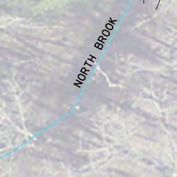
5 SOUTH BURLINGTON MULTI-SITE STORMWATER INFRASTRUCTURE ASSESSMENT SITE NO. 2 BARTLETT BAY ROAD CULVERT Overview August 28, OVERVIEW The City of South Burlington was awarded funding by the Chittenden County Regional Planning Commission to assess roadway and land-use impacts on water quality for four sites within the City. These four sites are: The Orchards Neighborhood and Streets Pine Tree Terrace Neighborhood and Streets Spear Street Culvert near the intersection of Deerfield Avenue and Nowland Farms Road Bartlett Bay Culvert Each of the above sites has been identified as having existing or emerging stormwater concerns, directly affecting local and regional water quality and increasing potential for flood damage to private and public properties. Relating to transportation, runoff from the transportation network directly contributes to the stormwater concerns. The City contracted with Stantec Consulting Services, Inc. (Stantec) to complete these assessments. The assessments include recommendations to improve water quality and/or reduce the potential for flood damage for each of these sites. The recommendations consider other local/regional activities or initiatives such as the mission of the South Burlington Stormwater Utility and Regional Stormwater Education Program (RSEP) as well as the regional efforts to improve water quality volume and meet TMDL standards. This report focuses on assessment and recommended improvements for the Bartlett Bay Road Culvert site. Runoff from a 210-acre densely developed drainage area runs into the North Brook. The North Brook is conveyed under Bartlett Bay Road via an existing 36 culvert. The 36 culvert is undersized and gets overwhelmed during large storm events. As a consequence, a drainage swale that runs along Bartlett Bay Road becomes overwhelmed and then overtops the road causing flooding and erosion issues across private properties. The goal of this assessment is to recommend improvements that will reduce the potential of the roadway overtopping. gc v:\1953\active\ \transportation\report\bartlett bay\bartlett bay report final.docx 1.1

6 SOUTH BURLINGTON MULTI-SITE STORMWATER INFRASTRUCTURE ASSESSMENT SITE NO. 2 BARTLETT BAY ROAD CULVERT Overview August 28, 2015 gc v:\1953\active\ \transportation\report\bartlett bay\bartlett bay report final.docx 1.1

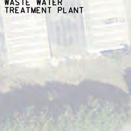
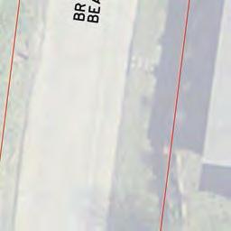
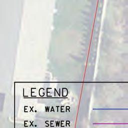
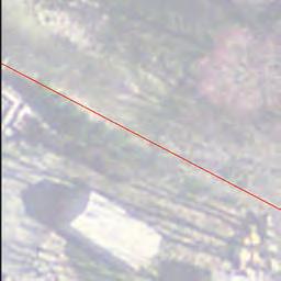
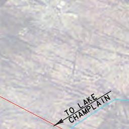
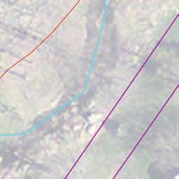
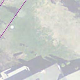
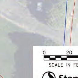
7 SOUTH BURLINGTON MULTI-SITE STORMWATER INFRASTRUCTURE ASSESSMENT SITE NO. 2 BARTLETT BAY ROAD CULVERT Overview August 28, Site Description A map showing the 210-acre drainage area and the North Brook is shown in Figure 1. Much of the area located east of the railroad tracks is densely developed and includes US Route 7 and surrounding commercial and residential development. Runoff from this area is conveyed to the Bartlett Bay Road culvert primarily from stormwater pipes located within the transportation network. Much of the runoff from nearby commercial and residential development discharges into the transportation network piping. The area drains to an existing 48 pipe culvert under the railroad tracks and into the North Brook. The brook is then conveyed under Bartlett Bay Road through the existing 36 pipe culvert before discharging into Lake Champlain approximately 750 southwest of the culvert outlet. The area west of the railroad tracks consists primarily of privately owned forest and meadow, the South Burlington Wastewater Treatment Plant and a cluster of private homes near the lake; and drains to the existing 36 pipe culvert through roadside swales and culverts located along Bartlett Bay Road and Lakeview Lane. Figure 1 - Overview of drainage area and discharge location Residents reported that runoff draining to the 36 pipe culvert backs up during heavy rain and causes a roadside swale, located west of the culvert and along Bartlett Bay Road, to overflow at a low point in the road and drain toward Lake Champlain as shown in Figure 2. The roadway overtopping causes occasional major flooding and damage to nearby properties. Video gc v:\1953\active\ \transportation\report\bartlett bay\bartlett bay report final.docx 1.1

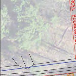
8 SOUTH BURLINGTON MULTI-SITE STORMWATER INFRASTRUCTURE ASSESSMENT SITE NO. 2 BARTLETT BAY ROAD CULVERT Overview August 28, 2015 evidence of the swale overflow and localized flooding of properties on Bartlett Bay Road was provided by residents. Residents have also observed stormwater inundating a nearby 24 culvert under Lakeview Lane, also causing roadway overtopping at the same location. Figure 2 - Diagram showing existing drainage pattern during large storm events Data Collection A topographic field survey was completed to gather locations, inverts and elevations of pertinent drainage features including pipes, culverts, swales and drainage structures. Photos of each drainage structure were provided with the field survey. A USGS soils map was used to determine the soil types in the area along with their Hydrologic Rating and boundaries. A high resolution aerial photo was used to determine locations of existing development and land type (I.E. Wooded, pasture, paved, etc.). A land and soil type heat map showing the Hydrologic Soil Rating and land type is shown in Figure 3 and contained in the appendix. Three-dimensional surfaces were developed from Lidar received from VCGI which were used to produce contours. The Lidar surface is also available to analyze any potential future grading. GIS information provided by the City of South Burlington was used to display approximate parcel boundaries, existing drainage infrastructure and utility information. A project base map showing much of this information is contained in the appendix. gc v:\1953\active\ \transportation\report\bartlett bay\bartlett bay report final.docx 1.2

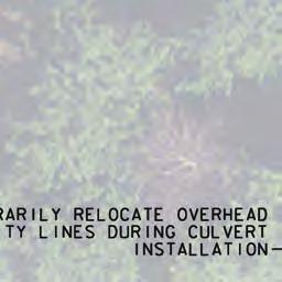
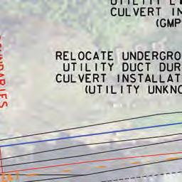
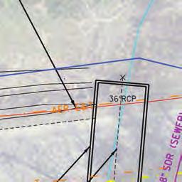
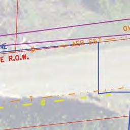
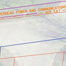
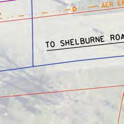
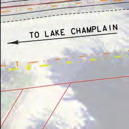
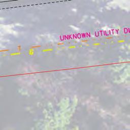
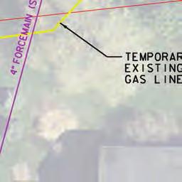
9 SOUTH BURLINGTON MULTI-SITE STORMWATER INFRASTRUCTURE ASSESSMENT SITE NO. 2 BARTLETT BAY ROAD CULVERT Overview August 28, 2015 An 8 ductile iron water main runs down the North Side of Bartlett Bay Road and around the end of the existing culvert approximately 6 below the surface. Also running along the north side of the road there is overhead Green Mountain Power utility lines that include power and telecommunications. A sewer line crosses under Bartlett Bay Road but not under the existing culvert. The sewer is the main outfall for the treatment plant and follows the North Brook stream channel out to the lake. VT Gas Systems provided as-builts that show a 2 gas line on the south side of Bartlett Bay road going over the culvert. An unknown underground duct is also shown on these as-builts that goes along the south side of the road over the culvert. The depths, sizes and exact locations of these utilities are unknown and are based on GIS information and as-builts. As-builts from the VTrans US Route 7 roadway reconstruction project completed in 2006 and the as-builts for the IDX ponds provided additional information on the existing stormwater infrastructure. As-builts for the waste water treatment plant outlet pipe verify the sewer line does not cross the existing 36 culvert under Bartlett Bay Road. As-builts can be found in the appendix. Figure 3 Hydrologic Soil Map gc v:\1953\active\ \transportation\report\bartlett bay\bartlett bay report final.docx 1.3
10 SOUTH BURLINGTON MULTI-SITE STORMWATER INFRASTRUCTURE ASSESSMENT SITE NO. 2 BARTLETT BAY ROAD CULVERT Assessment of Culvert Capacity August 28, ASSESSMENT OF CULVERT CAPACITY Existing conditions stormwater models were developed to determine the peak runoff rate discharging to the 36 culvert and the roadside culvert passing under Lakeview Lane. The peak rates were then compared to the existing capacity to determine if the culverts are undersized Design Criteria Design criteria for the existing 36 culvert were gathered from a variety of sources and are summarized in the appendix. The Vermont Agency of Transportation Hydraulics Manual, 1998 recommends culverts under local roads and streets to be able to pass the 25-year flood frequency with a headwater to depth ratio of no greater than 1.5. The City of South Burlington Land Development Regulations, Article E.(2) specify that All drainage structures shall be designed, at a minimum, to safely pass the twenty-five year, twenty-four hour (4.0 inch) rain event, to accommodate upstream development. Design criteria for the roadway culvert is in the appendix Stormwater Modeling Culvert Using the contours produced from the Lidar the entire drainage basin getting to the culvert was delineated and then field verified. The total basin drainage area is approximately 210 acres. That basin was then broken into sub-basins and analyzed individually to obtain peak flow and total runoff volume. Peak runoff rates and total runoff volumes at the culvert inlet were calculated for the 1, 10 and 25-year storm frequencies using NRCS TR55 methodology (HydroCAD software). Antecedent Moisture Content (AMC) values of 2 and 3 were applied to each storm event. An AMC value of 2 assumes the underlying soils in the drainage basin have an average moisture content. Analysis using AMC 2 is the industry standard design condition for New England. An AMC value of 3 assumes the underlying soils in the drainage basin are near saturated more closely simulating back-to-back storm events. As-builts for some of the existing stormwater infrastructure provided information to model a flow splitter on Bartlett Bay Road and to model the IDX ponds in front of GE Healthcare. See the appendix for specific details on the locations of the sub basins and how they were analyzed. Peak flows, peak elevations and total runoff volume at the 36 culvert inlet for each analysis are summarized in Table 1. gc v:\1953\active\ \transportation\report\bartlett bay\bartlett bay report final.docx 2.4
11 SOUTH BURLINGTON MULTI-SITE STORMWATER INFRASTRUCTURE ASSESSMENT SITE NO. 2 BARTLETT BAY ROAD CULVERT Assessment of Culvert Capacity August 28, 2015 AMC 2 AMC 3 Storm Frequency Peak Flow (cfs) Runoff Volume (Acre-ft) Peak Elevation (ft) Peak Flow (cfs) Runoff Volume (Acre-ft) Peak Elevation (ft) 36 Culvert Capacity Year Overtops road Overtops road 10 Year Overtops road Overtops road 25 Year Overtops road Overtops road Table 1 - Peak flow and runoff volume at culvert inlet for 36 culvert Lakeview Lane Culvert Residents have also reported roadway overtopping during storm events due to water backing up in the swale just west of the 24 culvert under Lakeview Lane. Residents have suggested that this happens sometimes without water backing up from the 36 culvert under Bartlett Bay Road. The drainage area, approximately 20 acres, to the Lakeview Lane culvert was modeled to calculate peak runoff rates, total runoff volumes and peak elevations at the culvert inlet for the 1, 10 and 25-year storm frequencies. This information is summarized in Table 2. The peak flow at which the roadway overwhelms the culvert and overtops the roadway was calculated to be 7 cfs. Comparing this peak flow to the values shown in Table 2 indicates that this culvert does not have the capacity to drain just over a 1-year storm event from the 20 acre drainage area without roadway overtopping. gc v:\1953\active\ \transportation\report\bartlett bay\bartlett bay report final.docx 2.5
12 SOUTH BURLINGTON MULTI-SITE STORMWATER INFRASTRUCTURE ASSESSMENT SITE NO. 2 BARTLETT BAY ROAD CULVERT Assessment of Culvert Capacity August 28, 2015 AMC 2 AMC 3 Storm Frequency Peak Flow (cfs) Runoff Volume (Acre-ft) Peak Elevation (ft) Peak Flow (cfs) Runoff Volume (Acre-ft) Peak Elevation (ft) Lakeview Lane Culvert (24 ) Capacity Year Overtops road Overtops road 10 Year Overtops road Overtops road 25 Year Overtops road Overtops road Table 2 - Peak flow and runoff volume at culvert inlet for Lakeview Lane culvert The information in Table 2 accounts for the 20-acre drainage area to the Lakeview Lane culvert and stormwater from the larger 210-acre area that drains to the undersized 36 culvert and backs up through the roadside swale and culverts along Bartlett Bay Road. gc v:\1953\active\ \transportation\report\bartlett bay\bartlett bay report final.docx 2.6

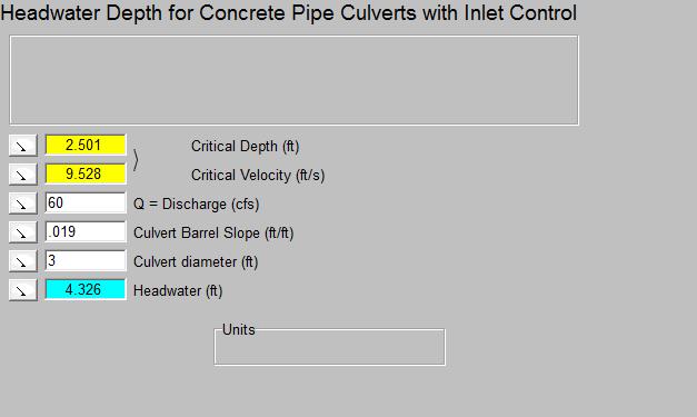
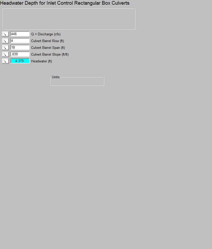
13 SOUTH BURLINGTON MULTI-SITE STORMWATER INFRASTRUCTURE ASSESSMENT SITE NO. 2 BARTLETT BAY ROAD CULVERT Solutions August 28, SOLUTIONS Two options were explored to decrease the likelihood of roadway overtopping on Bartlett Bay Road. The options explored were increasing the capacity of the culvert or reducing the peak flow to the culvert Increasing Culvert Capacity Culvert Increasing the size of the culvert will allow more flow to pass under the road and minimize the potential for roadway overtopping. Using the FHWA Nomograph Software, a number of culverts were sized to allow runoff to pass each storm without overtopping the road. The culvert rise was limited to 4 to allow for at least 3 of cover over the culvert and allow room for the existing gas line while maintaining the existing culvert inlet invert elevation (109.58). The results are summarized in Table 3. The analysis suggests that a box culvert with a 13 x4 hydraulic opening will have adequate capacity to pass the 25-year, AMC 2 storm event and a box culvert with a 17 x4 hydraulic opening will have adequate capacity to pass the 25-year, AMC 3 storm event. See photo below for an example of a box culvert. Figure 4 - Example Photo of a Box Culvert gc v:\1953\active\ \transportation\report\bartlett bay\bartlett bay report final.docx 3.7
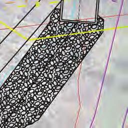
14 SOUTH BURLINGTON MULTI-SITE STORMWATER INFRASTRUCTURE ASSESSMENT SITE NO. 2 BARTLETT BAY ROAD CULVERT Solutions August 28, 2015 Hydraulic Opening Capacity Max. Passable Storm Frequencies (Peak Flow) Existing 36 RCP 60 cfs - 48 RCP w/ headwall 83 cfs - 6 x3 133 cfs 1 year (85 cfs) 6 x4 148 cfs 1 year (85 cfs) 7 x3 155 cfs 1 year (85 cfs) 8 x4 198 cfs 10 year (194 cfs) 9 x3 200 cfs 10 year (194 cfs) 9 x4 223 cfs 10 year (194 cfs) 10 x3 222 cfs 10 year (194 cfs) 10 x4 247 cfs 10 year (194 cfs) 11 x3 245 cfs 10 year (194 cfs) 12 x4 297 cfs 25 year (288 cfs) 13 x4 322 cfs 25 year (288 cfs) 14 x4 347 cfs 25 year (288 cfs) 15 x4 371 cfs 25 year (288 cfs) 16 x4 396 cfs 25 year AMC 3 (390 cfs) 17 x4 421 cfs 25 year AMC 3 (390 cfs) 18 x4 446 cfs 25 year AMC 3 (390 cfs) Table 3 - Results of culvert capacity calculations The ANR stream alteration permit requires a minimum 1.5 feet of embedment in box culverts to promote wild life passage and maintain stream velocities. ANR Stream Alteration Permit requirements can be found on the ANR website at: The actual physical opening required will be 1.5 feet plus the height of the hydraulic opening. Downstream impacts to the existing channel were analyzed to be sure it can handle the proposed increase in flow and change in velocity due to the increased culvert size. A Manning s analysis was completed to calculate stream capacity. The calculated stream capacity is approximately 3,800 cfs. The analysis indicates that the stream has adequate capacity to handle the increased flow without increasing the risk of downstream flooding or property damage. The calculated velocity for the 25 year storm event passing through the proposed 13 x4 box culvert is approximately 5.5 ft/sec. Velocities were calculated using Manning s equation. The velocity under the proposed condition is not considered erosive. The stream down to the lake is generally in good condition. The stream bed contains pebbles and large boulders. The area directly following the culvert has formed a pool due to the elevated gc v:\1953\active\ \transportation\report\bartlett bay\bartlett bay report final.docx 3.8


15 SOUTH BURLINGTON MULTI-SITE STORMWATER INFRASTRUCTURE ASSESSMENT SITE NO. 2 BARTLETT BAY ROAD CULVERT Solutions August 28, 2015 outlet. There is also some evidence of bank undercutting. However, other than the required culvert outlet protection, additional downstream alterations are not recommended. Figure 5 - Inlet and outlet of existing 36" concrete culvert Figure 6 - Downstream Condition Replacing the existing culvert will require contacting permitting agencies, utility companies and impacted property owners. The ANR River Management Engineer for South Burlington determined the project will require an ANR Stream Alteration General Permit under the category of Reporting Activities Not Requiring an Application. The Army Corps of Engineers (ACOE) should be notified of the work being completed since the project is in the vicinity of mapped Class II wetlands. The project is likely to qualify for Category 1 of the ACOE VT General Permit. Vermont Gas Systems will need to be contacted to discuss the temporary or permanent relocation of their gas line located above the culvert on the south side of Bartlett Bay Road. Designer and contractor are to coordinate with Green Mountain Power along with the other gc v:\1953\active\ \transportation\report\bartlett bay\bartlett bay report final.docx 3.9
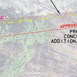
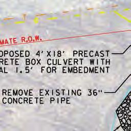
16 SOUTH BURLINGTON MULTI-SITE STORMWATER INFRASTRUCTURE ASSESSMENT SITE NO. 2 BARTLETT BAY ROAD CULVERT Solutions August 28, 2015 communication companies including Comcast and Fairpoint to decide the best course of action to manage their overhead power lines during construction. Options include temporary or permanent relocation, temporary de-energizing, or leaving in place. An As-built plan for the gas line also shows an underground communication duct on the south side of Bartlett Bay road. Utility companies have been contacted but are not able to verify the owner of the duct. If active, this duct will need to be permanently or temporarily relocated. A waterline runs along the north side of Bartlett Bay Road. As-builts provided by the Champlain Valley Water District show that the waterline goes around the end of the existing culvert and may remain in-place during construction. Contacts for utility companies are as follows: Green Mountain Power: Joe Bobee, joe.bobee@greenmountainpower.com Vermont Gas: Matt Anderson, Fairpoint: Melissa Rudnick, mrudnick@fiarpoint.com, Comcast: Jeremy Cota, Jeremy_cota@cable.comcast.com Champlain Water District: John Tymecki, johnt@cwd-h2o.org, According to the as-builts, the existing culvert is located within the City-owned three-rod Rightof-Way (ROW). Temporary easements will likely be needed to construct the culvert but no permanent easements are anticipated at this point. An additional ROW investigation will need to be done to determine the magnitude of easements required. Estimated costs for new 13 x4 and 17 x4 concrete box culverts (with an additional 1.5 for embedment) are shown in Table 4 and Table 5. Costs are construction costs only and do not include costs for Preliminary Engineering, Right-of-Way acquisition, maintenance or construction engineering. Costs are determined for July 2015 and should be adjusted for inflation based on anticipated construction year. gc v:\1953\active\ \transportation\report\bartlett bay\bartlett bay report final.docx 3.10
17 SOUTH BURLINGTON MULTI-SITE STORMWATER INFRASTRUCTURE ASSESSMENT SITE NO. 2 BARTLETT BAY ROAD CULVERT Solutions August 28, 2015 Culvert Designed for 25 Year AMC 2 $/UNIT TOTAL UNIT Cost Excavation/Backfill $ LF $ 32,500 13'x5.5' Box $ 1, LF $ 60,000 Roadway $ 5,000 1 LS $ 5,000 Stream Bed Material (1.5' Embedment) $ CY $ 4,000 Stone Fill Type II $ CY $ 2,400 Stream Diversion $ 20,000 1 LS $ 20,000 Traffic Control 5% LS $ 6,200 EPSC 3% LS $ 3,800 Mobilization/Demobilization 10% LS $ 12,400 Contingency 30% LS $ 43,900 Subtotal: $ 190,200 Rounding: $ 9,800 Opinion of Probable Construction Cost: $ 200,000 Table 4 - Opinion of probable construction cost for new 13'x4' Concrete Box Culvert Culvert Designed for 25 Year AMC 3 $/UNIT TOTAL UNIT Cost Excavation/Backfill $ LF $ 37,500 17'x5.5' Box $ 2, LF $ 100,000 Roadway $ 6,000 1 LS $ 6,000 Stream Bed Material (1.5' Embedment) $ CY $ 5,000 Stone Fill Type II $ CY $ 4,000 Stream Diversion $ 20,000 1 LS $ 20,000 Traffic Control 5% LS $ 8,700 EPSC 3% LS $ 5,200 Mobilization/Demobilization 10% LS $ 17,300 Contingency 30% LS $ 61,200 Subtotal: $ 264,900 Rounding: $ 10,100 Opinion of Probable Construction Cost: $ 280,000 Table 5 Opinion of probable construction cost for new 17'x4' Concrete Box Culvert Construction of the culvert will presumably be completed in two parts. Half of the roadway will be excavated and a crane will drop parts of the precast structure in. The other half the roadway will be open to one-way alternating traffic. Once the first half is complete it will be opened to traffic and the second half of the precast structure will be constructed. The stream will need to be temporarily diverted during construction of the culvert. gc v:\1953\active\ \transportation\report\bartlett bay\bartlett bay report final.docx 3.11

18 SOUTH BURLINGTON MULTI-SITE STORMWATER INFRASTRUCTURE ASSESSMENT SITE NO. 2 BARTLETT BAY ROAD CULVERT Solutions August 28, Lakeview Lane Culvert Figure 7 - Typical Installation of a Precast Box Culvert Increasing the size of the Lakeview Lane culvert is not an option because the roadway cover is approximately one foot. Damage to culverts can occur due to vehicle loading if roadway cover is less than one foot. A secondary relief culvert that drains runoff directly to Lake Champlain, as shown in Figure 8, would provide capacity to significantly reduce the likelihood of roadway overtopping if the 36 culvert under Bartlett Bay Road is also replaced. The relief culvert would consist of two 18 smooth pipe culverts under Bartlett Bay Road, two new drainage manholes on the west side of the road, and a new run of 30 smooth pipe along the north side of the 56 Bartlett Bay Road parcel outletting to Lake Champlain. Two 18 pipes are recommended under Bartlett Bay Road due to the need for a minimum one foot of cover over the pipes. Three potential locations for this outlet were explored. There is a small swale north of 56 Bartlett Bay Road that a previous homeowner constructed to redirect flood waters. This may be a possible location for the new 30 outlet pipe if the City can obtain permission from the landowner to get a 20 wide easement to provide for future maintenance. An alternative location for the relief culvert is down the private drive just south of 54 Bartlett Bay Road and thru the driveway and lawn of 50 Bartlett Bay Rd. Currently this home is being redeveloped which opens the opportunity to install an outlet pipe as a condition of their permit. Green Mountain Power owns a 5 wide easement along the northern property line of 54 Bartlett Bay Road. This may be a possible location for the new 30 outlet pipe if the City can obtain permission from the landowner and GMP to use and expand this easement. The land records for this easement are contained in the appendix. The issue with this alternative is the added complication of the GMP easement. gc v:\1953\active\ \transportation\report\bartlett bay\bartlett bay report final.docx 3.12

19 SOUTH BURLINGTON MULTI-SITE STORMWATER INFRASTRUCTURE ASSESSMENT SITE NO. 2 BARTLETT BAY ROAD CULVERT Solutions August 28, 2015 Figure 8 - Recommended improvements for Lakeview Lane culvert The proposed relief culvert was modeled with and without upgrades to the existing 36 culvert under Bartlett Bay Road to calculate peak runoff rates, total runoff volumes and peak flow elevations at the culvert inlet for the 1, 10 and 25-year storm frequencies. This information is summarized in Table 6 and Table 7. If the 36 pipe culvert is not replaced (Table 6), roadway overtopping is still expected to occur during the 1-year event as runoff backs up through the roadside swales. If the 36 culvert is replaced with a 13 x 4 box culvert (Table 7), the recommended improvements would increase capacity of the storm drain system to handle the 10-year AMC 2 storm event. gc v:\1953\active\ \transportation\report\bartlett bay\bartlett bay report final.docx 3.13
20 SOUTH BURLINGTON MULTI-SITE STORMWATER INFRASTRUCTURE ASSESSMENT SITE NO. 2 BARTLETT BAY ROAD CULVERT Solutions August 28, 2015 AMC 2 AMC 3 Storm Frequency Peak Flow (cfs) Runoff Volume (Acre-ft) Peak Elevation (ft) Peak Flow (cfs) Runoff Volume (Acre-ft) Peak Elevation (ft) Lakeview Lane Culvert (24 ) + Relief Culvert Capacity Year Overtops road Overtops road 10 Year Overtops road Overtops road 25 Year Overtops road Overtops road Table 6 - Peak flow, runoff volume and elevation at at Lakeview Lane culvert inlet with existing 36 pipe culvert under Bartlett Bay Road AMC 2 AMC 3 Storm Frequency Peak Flow (cfs) Runoff Volume (Acre-ft) Peak Elevation (ft) Peak Flow (cfs) Runoff Volume (Acre-ft) Peak Elevation (ft) Lakeview Lane Culvert (24 ) + Relief Culvert Capacity Year Year Overtops road 25 Year Overtops road Overtops road Table 7 - Peak flow, runoff volume and elevation at Lakeview Lane culvert inlet with new 13 x4 box culvert under Bartlett Bay Road gc v:\1953\active\ \transportation\report\bartlett bay\bartlett bay report final.docx 3.14
21 SOUTH BURLINGTON MULTI-SITE STORMWATER INFRASTRUCTURE ASSESSMENT SITE NO. 2 BARTLETT BAY ROAD CULVERT Solutions August 28, 2015 Downstream impacts are not a concern since the proposed improvements will discharge directly to Lake Champlain. Adding the relief culvert may require a Vermont Lake Encroachment Permit if the pipe encroaches upon the shoreline as defined by the mean water level of Lake Champlain (95.5 feet). Estimated costs for the improvements are shown in Table 8. Costs are construction costs only and do not include costs for Preliminary Engineering, Right-of-Way acquisition, maintenance or construction engineering. Costs are determined for July 2015 and should be adjusted for inflation based on anticipated construction year. There are two 18 diameter driveway culverts between Lakeview Lane and the existing 36 pipe culvert under Bartlett Bay Road. Improvements to these culverts will also be necessary since they restrict flow towards the culvert under Bartlett Bay Road. Increasing the size of these culverts to 36 will provide additional capacity and allow more runoff to drain toward the culvert under Bartlett Bay Road. These improvements are shown in Figure 9. Costs to replace these culverts and to install a relief culvert are included in Table 8. Description Roadway Excavation and Existing Pipe Removal Trench Excavation for Swale Reconstruction and Outlet Pipe to Lake Roadway Backfill and Surface Material 18" CPEP(SL) 18" End Section 24" CPEP(SL) 24" End Section 30" CPEP(SL) 30" End Section 36" CPEP(SL) 36" End Section Reconstruct Gabian Wall at Outlet Precast Reinforced Concrete Manhole with Cast Iron Cover ALT 1 - Thru 56 Bartlett Bay Road ALT 2 - Thru 50 Bartlett Bay Road Unit Price 1 Total Unit Extension Total Unit Extension $ CY $3, CY $3,000 $ CY $8, CY $10,725 $6,000 1 LS $6,000 1 LS $9,000 $60 50 LF $3, LF $10,800 $300 2 EA $600 2 EA $600 $80 42 LF $3, LF $3,360 $600 2 EA $1,200 2 EA $1,200 $ LF $24, LF $28,500 $750 3 EA $2,250 3 EA $2,250 $ LF $5, LF $5,250 $900 2 EA $1,800 2 EA $1,800 $ CY $3,000 0 EA $0 $5,000 2 EA $10,000 2 EA $10,000 Subtotal $71,560 $86,485 Mobilization/Demobilization (10%) $7,156 $8,649 Traffic Control (5%) $3,578 $4,324 EPSC (3%) $2,147 $2,595 Contingency (30%) $25,332 $30,616 Subtotal $109,773 $132,668 Rounded Cost $110,000 $140, The unit prices are based on VTrans Project Bid Tabs or the 5-yr Average Price List gc v:\1953\active\ \transportation\report\bartlett bay\bartlett bay report final.docx 3.15

22 SOUTH BURLINGTON MULTI-SITE STORMWATER INFRASTRUCTURE ASSESSMENT SITE NO. 2 BARTLETT BAY ROAD CULVERT Solutions August 28, 2015 Table 8 - Opinion of probable construction cost for relief culvert and replacement of Lakeview Lane and driveway culverts Figure 9 - Recommended improvements for driveway culverts Decreasing Peak Flow to Culverts A detention basin or other form of storage upstream of the 36 culvert was explored to decrease the peak flow to the culvert and minimize the potential for roadway overtopping. Construction of a basin would have the added benefit of helping the City meet TMDL goals for Lake Champlain. Given the densely developed drainage area, detention basins would be ideally located downstream of the developed areas to maximize flow reduction and water quality benefit. One area to construct a detention pond would be north of the wastewater treatment plant as shown in Figure 10. The area hatched in green represents the drainage area that could be routed to a detention basin in this location. Analysis indicates that construction of a detention basin in this area would not capture enough runoff to prevent runoff from overtopping the roadway during a 25-year storm. In addition, a new culvert would need to be installed under the railroad embankment to route the runoff to this area. The chart below shows dimensions of dry detention basins required to reduce the flow to various box culvert sizes. gc v:\1953\active\ \transportation\report\bartlett bay\bartlett bay report final.docx 3.16
23 SOUTH BURLINGTON MULTI-SITE STORMWATER INFRASTRUCTURE ASSESSMENT SITE NO. 2 BARTLETT BAY ROAD CULVERT Solutions August 28, Pond Area vs. Culvert Size 25 Year (AMC 2) 'x224'x4' Pond Surface Area Required (SF) 'x198'x4' 523'x174'x4' 622'x207'x4' 544'x181'x4' 479'x160'x4' 'x3' 7'x3' 8'x3' 6'x4' 7'x4' 8'x4' Box Culvert Size under Bartlett Bay Rd Chart 1 - Pond Area vs. Culvert Size The cost of excavating and landscaping a pond this size in this area could be upwards of $500,000. There would also be a significant ROW acquisition cost for this property. Based on assessed value as shown on South Burlington s Grand List, acquisition costs could be close to $320,000 per acre. In addition, there would be the cost to install a larger culvert designed for the 50 year storm under the railroad which will include additional railroad fees. Cost to install this could range from $300,000 to $500,000 if allowed by the railroad. On top of these costs, a culvert would still need to be installed under Bartlett Bay Road since a basin could not be installed to reduce flows to the existing capacity of the culvert. The cost could range from $150,000 to $200,000. This alternative is very cost prohibitive. gc v:\1953\active\ \transportation\report\bartlett bay\bartlett bay report final.docx 3.17

24 SOUTH BURLINGTON MULTI-SITE STORMWATER INFRASTRUCTURE ASSESSMENT SITE NO. 2 BARTLETT BAY ROAD CULVERT Solutions August 28, 2015 Figure 10 - Potential pond location to detain part of drainage area Similar to the previous alternative, a smaller basin could be installed in this area to treat only the water quality volume in effort to meet future Lake Champlain TMDL requirements. A much smaller culvert could be used to redirect the water quality volume under the railroad and into the basin, while larger events bypass the pipe and stormwater will flow as it does today. Preliminary calculations show that an 18 culvert could be jack and bored under the railroad to convey this flow, approximately 5.02 cfs. The pond would be much smaller and require much less excavation at an approximate size of 130 x40 x4 which is sized to detain and release the water quality volume over 24 hours. A pond this size would cost close to $20,000 to $30,000. The cost to jack and bore under the railroad will require specific permits, applications and lease fees typically costing close to $10,000. Based on historical data, the construction cost will be somewhere in the range of $80,000 to $100,000. The downside to this alternative is that the pond will have little to no detention benefit for larger storms and to fix the flooding issue at Bartlett Bay Road a new culvert, as described above, would still need to be installed. A detention basin located between the wastewater plant and Bartlett Bay Road on City property was also explored. While a larger drainage area could be directed to this location, the grades and limited available land do not allow detention of the required volume of runoff to prevent roadway overtopping. Also, since this part of the brook falls under the jurisdiction of ANRs watershed management division, they won t permit any in stream detention. gc v:\1953\active\ \transportation\report\bartlett bay\bartlett bay report final.docx 3.18
25 SOUTH BURLINGTON MULTI-SITE STORMWATER INFRASTRUCTURE ASSESSMENT SITE NO. 2 BARTLETT BAY ROAD CULVERT Recommendations and Next steps August 28, RECOMMENDATIONS AND NEXT STEPS Reducing the risk of roadway overtopping and flood and erosion damage can be achieved by replacing the existing 36 culvert under Bartlett Bay Road and constructing a new relief culvert where the roadway currently overtops near 56 Bartlett Bay Road. Given the cost of the two improvements, replacing the 36 culvert could be considered a long-term improvement and constructing the relief culvert could be a short-term improvement. Both improvements will need to be constructed to provide sufficient capacity to eliminate roadway overtopping during the 10-year, AMC 2 storm event. Short-term Recommendation A relief culvert consisting of two 18 smooth pipe culverts under Bartlett Bay Road, two new drainage manholes on the west side of the road, and a new run of 30 smooth pipe outletting to Lake Champlain will have the capacity to drain a 10-year, AMC 2 storm event without roadway overtopping once the long-term recommendation is implemented. In addition, replacement of the existing 18 driveway culverts with 36 culverts will be necessary. If the 36 pipe culvert under Bartlett Bay Road is not replaced, roadway overtopping is still expected to occur during the 1-year storm event as runoff backs up through the roadside swales, albeit the volume of runoff that overtops the road will be reduced. Long-term Recommendation Construction of a 13 x 4 box culvert to replace the existing 36 culvert under Bartlett Bay Road is recommended to pass the 25-year, AMC 2 event. A culvert constructed of this size will be consistent with State design standards and City Land Development Regulations. A 17 x 4 box culvert will pass the 25-year, AMC 3 event and provide additional capacity with additional cost. It is recommended that a 13 x4 culvert be constructed at a minimum with a 17 x 4 culvert preferred to reduce the risk of roadway overtopping and localized flood and erosion damage. A conceptual plan for the 17 x 4 culvert has been included in the appendix. Next Steps The following outlines next steps recommended for the City to undertake if they choose to move forward with the project: Determine optimal location for relief culvert considering underground utilities and minimum cover. Secure funds for design and construction of the short and long-term improvements. Procure engineering and permitting services for culvert designs. Advertise bids, select contractor and construct project. gc v:\1953\active\ \transportation\report\bartlett bay\bartlett bay report final.docx 4.19
26 SOUTH BURLINGTON MULTI-SITE STORMWATER INFRASTRUCTURE ASSESSMENT SITE NO. 2 BARTLETT BAY ROAD CULVERT Appendix A Design Criteria August 28, 2015 Appendix A DESIGN CRITERIA A.1
27 PIPES: Min Pipe Diameter Highways: 18 Drives and paths: 15 Pipe Velocity Maximum: Consistent with velocity in natural channel or mitigate with channel stabilization or energy dissipation Minimum: 2.5 ft/sec Pipe Gradient Minimum: 0.4% Maximum: 10.0% Pipe Cover Minimum: 4 Maximum: cover not to exceed height of cover tables in VAOT Hydraulics Manual Pipe Capacity FHWA Nomographs PONDS: Minimum Freeboard: 1 Minimum Orifice Size: 3 Max Side slopes: 1:3 HYDROLOGY: Runoff method: Rainfall type: SCS TR-20 Type II 24-hr Rainfall: Per VT Stormwater Management Manual, Volume 1: 10 year: 3.2 inches 25 year: 4.1 inches
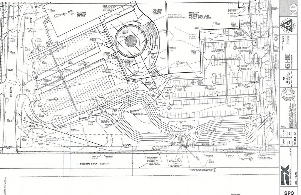
28 SOUTH BURLINGTON MULTI-SITE STORMWATER INFRASTRUCTURE ASSESSMENT SITE NO. 2 BARTLETT BAY ROAD CULVERT Appendix B Project Base Map August 28, 2015 Appendix B PROJECT BASE MAP B.1

29
30 SOUTH BURLINGTON MULTI-SITE STORMWATER INFRASTRUCTURE ASSESSMENT SITE NO. 2 BARTLETT BAY ROAD CULVERT Appendix C Stormwater Modeling August 28, 2015 Appendix C STORMWATER MODELING C.1
31
32 0P 1aS 12S 1bS 1cS Lake Bartlett Neighborhood West of Lakeview Bartlett 2 Bartlett 3 Bartlett 4 3R Stream to Lake 11P CB 6R 5R 4R 8R 9R 12P CB Turning MH Swale west of Lakeview with 2 outlet culverts Road Ditch 1 Drive Culvert 1 Road Ditch 2 Drive Culvert 2 Road Ditch 3 1P Proposed 18'x4' box culvert with storage 2S from stream basin 5S Goss Dodge 11S East of Route 7 and North of GE West of Tracks 10P CB 1R 48" Railroad Culvert Goss Dodge Channel 3S Magic Hat/Jiffy Lube 2R 6S 5P 4S Railroad Channel (East) Audi Grate magic hat/coin store 9S 6P 7P 10S 7S North (GE Healthcare) IDX pond (North) IDX Pond (South) South (GE Healthcare) Crate Escape, Shelburne Rd 4P CB 3P CB 8S Flow Splitter #1 Flow Splitter #2 Stantec/Car Dealerships/Farm etc. Subcat Reach Pond Link Routing Diagram for Bartlett Bay_proposed Prepared by {enter your company name here}, Printed 7/31/2015 HydroCAD s/n HydroCAD Software Solutions LLC
33 Bartlett Bay_proposed Prepared by {enter your company name here} HydroCAD s/n HydroCAD Software Solutions LLC Printed 7/31/2015 Page 2 Area (acres) CN Description (subcatchment-numbers) Area Listing (all nodes) /4 acre lots, 38% imp, HSG A (9S, 11S) /4 acre lots, 38% imp, HSG B (1aS, 11S, 12S) /4 acre lots, 38% imp, HSG C (9S, 11S) /4 acre lots, 38% imp, HSG D (1aS, 1bS, 9S, 11S, 12S) % Grass cover, Fair, HSG B (1aS, 5S, 6S) % Grass cover, Fair, HSG C (4S, 5S, 6S) % Grass cover, Fair, HSG D (1aS, 2S, 4S, 6S) >75% Grass cover, Good, HSG A (7S, 9S) >75% Grass cover, Good, HSG C (7S) Brush, Fair, HSG D (5S) Paved parking & roofs (7S) Paved roads w/curbs & sewers (2S, 3S, 4S, 5S, 6S) Row crops, SR + CR, Good, HSG A (8S) Urban commercial, 85% imp, HSG A (8S, 9S) Urban commercial, 85% imp, HSG B (9S, 11S) Urban commercial, 85% imp, HSG C (7S, 8S, 9S, 10S, 11S) Urban commercial, 85% imp, HSG D (7S, 9S, 11S) Urban industrial, 72% imp, HSG D (2S) Woods, Fair, HSG A (9S, 10S) Woods, Fair, HSG B (1aS, 2S, 6S) Woods, Fair, HSG C (1aS, 2S, 5S, 6S, 12S) Woods, Fair, HSG D (1aS, 1bS, 1cS, 2S, 3S, 5S, 6S, 12S) Woods, Poor, HSG A (8S) TOTAL AREA
34 Bartlett Bay_proposed Prepared by {enter your company name here} HydroCAD s/n HydroCAD Software Solutions LLC Printed 7/31/2015 Page 3 Area (acres) Soil Group Subcatchment Numbers Soil Listing (all nodes) HSG A 7S, 8S, 9S, 10S, 11S HSG B 1aS, 2S, 5S, 6S, 9S, 11S, 12S HSG C 1aS, 2S, 4S, 5S, 6S, 7S, 8S, 9S, 10S, 11S, 12S HSG D 1aS, 1bS, 1cS, 2S, 3S, 4S, 5S, 6S, 7S, 9S, 11S, 12S Other 2S, 3S, 4S, 5S, 6S, 7S TOTAL AREA
35 Bartlett Bay_proposed Type II 24-hr 1 year Rainfall=2.10" Prepared by {enter your company name here} Printed 7/31/2015 HydroCAD s/n HydroCAD Software Solutions LLC Page 4 Time span= hrs, dt=0.03 hrs, 1334 points Runoff by SCS TR-20 method, UH=SCS, Weighted-CN Reach routing by Stor-Ind+Trans method - Pond routing by Stor-Ind method Subcatchment 1aS: Bartlett Neighborhood Runoff Area= ac 5.79% Impervious Runoff Depth=0.43" Flow Length=2,227' Tc=36.9 min CN=75 Runoff=5.08 cfs af Subcatchment 1bS: Bartlett 3 Subcatchment 1cS: Bartlett 4 Subcatchment 2S: West of Tracks Subcatchment 3S: Magic Hat/Jiffy Lube Subcatchment 4S: magic hat/coin store Subcatchment 5S: Goss Dodge Runoff Area=2.070 ac 0.92% Impervious Runoff Depth=0.58" Flow Length=457' Tc=15.1 min CN=79 Runoff=1.45 cfs af Runoff Area=0.390 ac 0.00% Impervious Runoff Depth=0.58" Flow Length=296' Tc=27.6 min CN=79 Runoff=0.19 cfs af Runoff Area= ac 25.45% Impervious Runoff Depth=0.72" Flow Length=1,397' Tc=31.9 min CN=82 Runoff=6.39 cfs af Runoff Area=4.270 ac 71.90% Impervious Runoff Depth=1.41" Flow Length=781' Tc=5.0 min CN=93 Runoff=10.67 cfs af Runoff Area=219,813 sf 67.59% Impervious Runoff Depth=1.41" Flow Length=873' Tc=6.1 min CN=93 Runoff=12.15 cfs af Runoff Area=544,248 sf 57.84% Impervious Runoff Depth=1.11" Flow Length=1,429' Tc=5.8 min CN=89 Runoff=24.75 cfs af Subcatchment 6S: Audi Subcatchment 7S: Crate Escape, Subcatchment 8S: Stantec/Car Runoff Area=1,095,795 sf 53.05% Impervious Runoff Depth=1.05" Flow Length=2,792' Tc=24.1 min CN=88 Runoff=26.12 cfs af Runoff Area=471,353 sf 74.85% Impervious Runoff Depth=1.05" Flow Length=1,378' Tc=15.8 min CN=88 Runoff=14.26 cfs af Runoff Area=1,795,000 sf 53.04% Impervious Runoff Depth=0.67" Flow Length=2,543' Tc=37.7 min CN=81 Runoff=18.89 cfs af Subcatchment 9S: North (GE Healthcare) Runoff Area=837,921 sf 60.85% Impervious Runoff Depth=0.54" Flow Length=1,103' Tc=16.3 min CN=78 Runoff=11.76 cfs af Subcatchment 10S: South (GE Healthcare)Runoff Area=401,716 sf 70.04% Impervious Runoff Depth=0.82" Flow Length=1,442' Tc=15.2 min CN=84 Runoff=9.50 cfs af Subcatchment 11S: East of Route 7 and Runoff Area=1,920,404 sf 58.35% Impervious Runoff Depth=0.67" Flow Length=3,237' Tc=23.5 min CN=81 Runoff=27.93 cfs af Subcatchment 12S: Bartlett 2 Runoff Area=4.600 ac 16.60% Impervious Runoff Depth=0.67" Flow Length=974' Tc=26.3 min CN=81 Runoff=2.70 cfs af Reach 1R: Goss Dodge Channel Avg. Flow Depth=1.26' Max Vel=2.36 fps Inflow=31.96 cfs af n=0.080 L=924.0' S= '/' Capacity= cfs Outflow=29.02 cfs af Reach 2R: Railroad Channel (East) Avg. Flow Depth=0.65' Max Vel=3.97 fps Inflow=26.12 cfs af n=0.035 L=398.0' S= '/' Capacity= cfs Outflow=25.92 cfs af
36 Bartlett Bay_proposed Type II 24-hr 1 year Rainfall=2.10" Prepared by {enter your company name here} Printed 7/31/2015 HydroCAD s/n HydroCAD Software Solutions LLC Page 5 Reach 3R: Stream to Lake Avg. Flow Depth=1.62' Max Vel=3.95 fps Inflow=85.42 cfs af n=0.035 L=700.0' S= '/' Capacity=6, cfs Outflow=84.37 cfs af Reach 4R: Road Ditch 2 Avg. Flow Depth=0.76' Max Vel=1.42 fps Inflow=4.92 cfs af n=0.035 L=169.5' S= '/' Capacity=33.28 cfs Outflow=4.89 cfs af Reach 5R: Drive Culvert 1 Avg. Flow Depth=0.80' Max Vel=3.22 fps Inflow=4.38 cfs af 30.0" Round Pipe n=0.013 L=30.5' S= '/' Capacity=19.65 cfs Outflow=4.38 cfs af Reach 6R: Road Ditch 1 Avg. Flow Depth=0.72' Max Vel=1.36 fps Inflow=4.41 cfs af n=0.035 L=156.7' S= '/' Capacity=32.97 cfs Outflow=4.38 cfs af Reach 8R: Drive Culvert 2 Avg. Flow Depth=0.78' Max Vel=3.33 fps Inflow=4.89 cfs af 36.0" Round Pipe n=0.013 L=41.5' S= '/' Capacity=32.74 cfs Outflow=4.89 cfs af Reach 9R: Road Ditch 3 Pond 0P: Lake Avg. Flow Depth=0.78' Max Vel=1.42 fps Inflow=5.04 cfs af n=0.035 L=132.6' S= '/' Capacity=32.96 cfs Outflow=5.03 cfs af Inflow=84.37 cfs af Primary=84.37 cfs af Pond 1P: Proposed 18'x4' box culvert Peak Elev=110.70' Storage=10,578 cf Inflow=85.88 cfs af Primary=85.42 cfs af Secondary=0.00 cfs af Outflow=85.42 cfs af Pond 3P: Flow Splitter #2 Peak Elev=125.85' Inflow=8.97 cfs af Discarded=3.66 cfs af Primary=5.31 cfs af Outflow=8.97 cfs af Pond 4P: Flow Splitter #1 Peak Elev=136.21' Inflow=24.15 cfs af Primary=15.18 cfs af Secondary=8.97 cfs af Outflow=24.15 cfs af Pond 5P: Grate Peak Elev=154.00' Storage=0 cf Inflow=0.00 cfs af Outflow=0.00 cfs af Pond 6P: IDX pond (North) Peak Elev=156.99' Storage=1.332 af Inflow=14.71 cfs af Primary=6.14 cfs af Secondary=0.00 cfs af Outflow=6.14 cfs af Pond 7P: IDX Pond (South) Peak Elev=156.39' Storage=0.440 af Inflow=9.50 cfs af Primary=3.80 cfs af Secondary=0.00 cfs af Outflow=3.80 cfs af Pond 10P: 48" Railroad Culvert Peak Elev=123.16' Inflow=74.85 cfs af Outflow=74.85 cfs af Pond 11P: Swale west of Lakeview with 2 outlet culverts Peak Elev=112.79' Inflow=5.08 cfs af Primary=2.00 cfs af Secondary=3.08 cfs af Outflow=5.08 cfs af Pond 12P: Turning MH Peak Elev=110.26' Inflow=3.08 cfs af 30.0" Round Culvert n=0.013 L=214.0' S= '/' Outflow=3.08 cfs af Total Runoff Area = ac Runoff Volume = af Average Runoff Depth = 0.77" 49.63% Pervious = ac 50.37% Impervious = ac
37 Bartlett Bay_proposed Type II 24-hr 1 year Rainfall=2.10" Prepared by {enter your company name here} Printed 7/31/2015 HydroCAD s/n HydroCAD Software Solutions LLC Page 6 Summary for Subcatchment 1aS: Bartlett Neighborhood West of Lakeview Runoff = hrs, Volume= af, Depth= 0.43" Runoff by SCS TR-20 method, UH=SCS, Weighted-CN, Time Span= hrs, dt= 0.03 hrs Type II 24-hr 1 year Rainfall=2.10" Area (ac) CN Description % Grass cover, Fair, HSG B % Grass cover, Fair, HSG D Woods, Fair, HSG B Woods, Fair, HSG C Woods, Fair, HSG D /4 acre lots, 38% imp, HSG B /4 acre lots, 38% imp, HSG D Weighted Average % Pervious Area % Impervious Area Tc Length Slope Velocity Capacity Description (min) (feet) (ft/ft) (ft/sec) (cfs) Sheet Flow, Grass: Dense n= P2= 2.30" , Shallow Concentrated Flow, Unpaved Kv= 16.1 fps Trap/Vee/Rect Channel Flow, Bot.W=3.00' D=2.00' Z= 2.0 '/' Top.W=11.00' n= Earth, dense weeds ,227 Total
38
39
40
41 SOUTH BURLINGTON MULTI-SITE STORMWATER INFRASTRUCTURE ASSESSMENT SITE NO. 2 BARTLETT BAY ROAD CULVERT Appendix D Conceptual Plan August 28, 2015 Appendix D CONCEPTUAL PLAN D.1


42
43 SOUTH BURLINGTON MULTI-SITE STORMWATER INFRASTRUCTURE ASSESSMENT SITE NO. 2 BARTLETT BAY ROAD CULVERT Appendix E As-Builts August 28, 2015 Appendix E AS-BUILTS E.1
44
45
46
47
48
49 SOUTH BURLINGTON MULTI-SITE STORMWATER INFRASTRUCTURE ASSESSMENT SITE NO. 2 BARTLETT BAY ROAD CULVERT Appendix F Soil and Land Type Heat Map August 28, 2015 Appendix F SOIL AND LAND TYPE HEAT MAP F.1
50
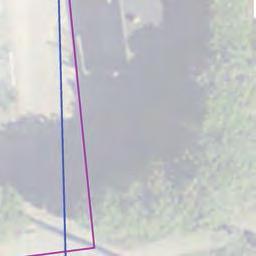
51 SOUTH BURLINGTON MULTI-SITE STORMWATER INFRASTRUCTURE ASSESSMENT SITE NO. 2 BARTLETT BAY ROAD CULVERT Appendix G Land Records August 28, 2015 Appendix G LAND RECORDS G.2

52 J V: 1144 PG: 3 1 t TRUSTEES' DEED KNOW ALL PERSONS BY THESE PRESENTS THAT we, JANEK. GARDNER., of South Burlington, in the County of Chittenden, State ofvennont, and JOSEPH D. FALLON, of Hinesburg, in the County of Chittenden, State of Vermont, as SUCCESSOR CO-TRUSTEES OF THE RESTATED WALTER H. GARDNER FAMILY TRUST Uff/A JUNE 4, 2010, AS AMENDED, and JANEK. GARDNER, of South Burlington, in the County of Chittenden, State of Vermont, as TRUSTEE OF THE RESTATED JANEK. GARDNER FAMILY TRUST Uff/A DATED JUNE 4, 2010, AS AMENDED, Grantors, (hereinafter "Grantors"), in consideration of -----TEN AND MORE---- Dollars paid to our full satisfaction by KENDALL SCOTT GARDNER, of South Burlington, in the County of Chittenden, State ofvennont, Grantee, by these presents, do freely GIVE, GRANT, SELL, CONVEY AND CONFIRM Wlto the said Grantee, KENDALL SCOTT GARDNER, and his heirs and assigns forever, a certain piece of land in the City of South Burlington, in the County of Chittenden, and State ofvennont, described as follows, viz: Being all and the same land and premises, together with improvements thereon and appurtenances thereto, conveyed to Walter H. Gardner and Jane K. Gardner, as Co-Trustees of the Restated Walter H. Gardner Family Trust ult/a June 4, 2010, and Jane K. Gardner and Walter H. Gardner, as Co-Trustees of the Restated Jane K. Gardner Family Trust u/tfa June 4, 2010, bywammty Deed of Walter H. Gardner and Jane K. Gardner dated June 4, 2010, and of record in Book 937, Pages of the City of South Burlington Land Records. Being all and the same land and premises, together with improvements thereon and appurtenances thereto, conveyed to Walter H. Gardner and Jane K. Gardner by Warranty Deed of George H. Bowers, Jr. and Barbara L. Bowers, Trustees of the George H. Bowers, Jr. and Barbara L. Bowers Revocable Trust, Uff/A dated November 4, 2005, said deed dated September 14, 2009, and of record in Book 893, Page 163 of the City of South Burlington Land Records. Said land and premises are depicted as "0.41 Acres, Walter H. & Jane K. Gardner, Bk 893 Pg 163" on a survey entitled, "Survey Plat of lands belonging to Walter H. & Jane K. Gardner, 56 Bartlett Bay Road, City of South Burlington, Chittenden CoWlty, Vermont", prepared by South MoWltain Surveying & Mapping, P.C., dated January 18, 2010, and of record in Map Slide 543, Page 3 of the City of South Burlington Land Records. Said land and premises are known and designated as 56 Bartlett Bay Road, South Burlington, Vennont. Reference is hereby made to the above-mentioned instrwnents, the records thereof, the references therein made, and their respective records and references, in further aid of this description. JOSEPH D. FALLON ATTOAHEV AT LAW P.0.90XU'P tot29 ROUTa: '1 tlneslluacl, YT O! TO HA VE ANO TO HOLD said granted premises, with all the privileges and appurtenances thereof, to the said Grantee, KENDALL SCOTT GARDNER, and his heirs and assigns, to their own use and behoof forever; and we, the said Grantors, for ourselves and our heirs, executors and administrators, do covenant with the said Grantee, KENDALL SCOTT GARDNER, and his heirs and assigns, that until the ensealing of these presents we are the sole owners of the premises, and have good right and title to convey the same in ITV. CLERK'S. OFFICE i Received 1111' 08r201J \ Record..i in _IJllL:. u+tp6: ~Z3" 1 Of. So._lur_l in1toa l.4nd R'cor ds Att.!E!.s.t : Donnm l<. ln~tlle.. Cits cterk II
53 V: 1144 PG: 3 2 tl Sb manner aforesaid, that they are FREE FROM EVERY ENCUMBRANCE except as aforesaid and except for easements and rights of way of record, if any, and except for taxes and municipal charges hereafter due and payable, which have been prorated as of the date of closing, and which the Grantee accordingly assumes and agrees to pay; and we hereby engage to WARRANT AND DEFEND the same against all lawful claims whatever, except as aforesaid. IN WITNESS WHEREOF, we hereunto set our hands and seals this :::/-;...day of March, RESTATED WALTER H. GARDNER FAMILY TRUST,f'..Jr.o "'""" By J. (Jane K. Gardne, o Trustee STATE OF VERMONT CHITTENDEN COUNTY, SS. RESTATED JANEK. GARDNER FAMILY TRUST By:..k,. f< ~., ol ' ' Gane K. Gardner, Trustee At Hinesburg, in said County, this.1_ day of March, 2013, personally appeared JANEK. GARDNER, SUCCESSOR CO-TRUSTEE OF THE RESTATED WALTER H. GARDNER F AMfl.., Y TRUST, who acknowledged the foregoing instn.unent, by her sealed and subscribed, to be her free act and deed, and the free act and deed of the RESTATED WALTER H. GARDNER FAMILY TRUST. Bcf~m J~fl/ ~ /N'J(j.Y PUBLIC STATE OF VERMONT CHITTENDEN COUNTY, SS. ~.f- My commission expires: 2110/2015.IOSEPH D. FAU.oN AT'TORNEV T ~W P:.O. 9QX. 297 to"l'z ROUTE 11G HINESBURG. VT Ofi.491 At Hinesburg, in said County, this l_ day of March, 2013, personally appeared JOSEPH D. FALLON, SUCCESSOR CO-TRUSTEE OF THE RESTATED WALTER H. GARDNER FAMILY TRUST, who acknuw led8ed the foregoing instrument, by him scaled and subscribed, to be his free act and deed, and the free act and deed of the RESTATED WALTER H. GARDNER FAMILY TRUST. ~ /14;& Before moo ~ YP LIC My commission expires: 2/10/2015 2,-. :-: i ~1 - - ~ -
54 V~ PG: 3 3 STATE OF VERMONT CHITTENDEN COUNTY, SS. At Hinesburg, in said County, this 1"' day of March, 2013, personally appeared JANEK. GARDNER, TRUSTEE OF THE RESTATED JANEK. GARDNER FAMILY TRUST, who acknowledged the foregoing instrument, by her sealed and subscribed, to be her free act and deed, and the free act and deed of the RESTATED JANEK. GARDNER FAMILY TRUST. &fore~~,~ /NO PUBIC My commission expires: 2/10/2015 Yenaat ProPerh Tronsrer TllX 32 V~S.A. Chap 231 -ACKNOWLEOGEMENT RETURH REC'l>-TAX PAID MMRO OF HEALTH CERT, REC'D. YT LAlll> USE 1 DEVElDl'llOO PLAHS ACT. CERT. REC '0 Return Ho Donna Kinville Cih Clerk D4h n~r 08r2013 JOSEPH D. FAu.ON ATT'OftN&'V AT LAW END OF DOCUMENT P.O. BOX21!1il 10?29 ROUTE 11 ~.VTOS '. ~,....:.
55 v: 961 PG: 146 TRUSTEE'S WARRANTY DEED KNOW ALL MEN BY THESE PRESENTS that I Carole H. Meserole, Trustee of the Revocable Trust Agreement of Carole H. Meserole, executed December 26, 1991, as amended and restated in its entirety March 9, 2010, of Shelburne, in the County of Chittenden, and State of Vennont, Grantor, in the consideration of TEN OR MORE Dollars, paid to my full satisfaction by Michael M. Metz and Denise Sbekerjian, or their successors In Trust, as Trustees of the Michael M. Metz Revocable Trust dated November 5, 1993, as amended and restated in its entirety by agreement dated December 16, 2009 (the "MMM Trust" as to an undivided Yi interest) and Denise Shekerjian and Michael M. Metz, or their successors In Trust, as Trustees of the Denise Shekerjian Revocable Trust dated November 5, 1993, as amended and restated in its entirety by agreement dated December 16, 2009 (the "OS Trust" as to an undivided Yi interest) of Charlotte, County of Chittenden, and State of Vermont, (the MMS Trust and the DS Trust, together, the Grantees), by these presents, do freely GIVE, GRANT, SELL, CONVEY and CONFIRM unto the said, Michael M. Metz and Denise Shekerjian, as Trustees of the MMS Trust and Denise Shekerjian and Michael M. Metz as Trustees of the DS Trust, as tenants in common, and their heirs and assigns forever, a certain piece ofland in the City of South Burlington, in the County of Chittenden, and State of Vermont, described as follows: Being all and the same lands and premises conveyed to Carole H. Meserole and Jere S. Meserole (now deceased), Trustees of the Revocable Trust Agreement of Carole H. Meserole, executed December 26, 1991 by Warranty Deed of Jere S. Meserole and Carole H. Meserole, Trustees of the Jere S. Meserole 1993 Revocable Trust executed October 8, 1993, dated January 20, 2000 and recorded in Volume 469 at Page 697 of the City of South Burlington Land Records. Also being all and the same lands and premises conveyed to Jere S. Meserole and Carole H. Meserole, Trustees of the Jere S. Meserole 1993 Trust, executed on October 8, 1993 and Carole H. Meserole and Jere S. Meserole, Trustees of the Revocable Trust Agreement of Carole H. Meserole, executed December 26, 1991, by Warranty Deed of Edward L. Austin, Jr. and Mary A. Conzelman, dated June 20, 1994 and recorded in Volume 364, and Page 86 of said land records. The lands and premises are further described as follows: ( ) CITY CLERK'S OFFICE Recei ved Oct O'r :30A Recorded in VOL: 961 PG: 146,-IJf'I OF So. 8urlin9ton Land Records Attest: l>onno. Kinville City Clerk

56 v: 961 PG: 1""7 "Parcel No. 1. All of Lot No. 1 with all buildings thereon as laid down on a plan of Camp Bartlett, property of Roy R. Bartlett, South Burlington, Vermont, J. H. Sinclair, C.E., recorded in Volume 8, Page 597 of the South Burlington Land Records. Said parcel hereby conveyed is shown on said plan as having a westerly line of seventy-six and two tenths feet ( ), an easterly line of seventy-five and seven hundredths feet (75.07'), a northerly line of one hundred eighty feet (180'), more or less, and a southerly line of one hundred sixty-seven feet (167 1 ), more or less. Parcel No. 2. A strip of land of uniform width of five feet (5 1 ) lying northerly and immediately adjacent and contiguous to the northerly line of said Lot No. 1, and extending from the westerly line to the easterly line of said Lot No. 1, all as shown on the above described plan. The within conveyed premises are subject to a utility easement conveyed by the Grantors to Green Mountain Power Corporation by instrument dated October 2, 1979 and of record in Volume 157 Page 261 of the South Burlington Land Records. The within conveyed premises are subject to those conditions set forth in a conditional warranty deed from Marjorie F. Ladue to Roy R. and Catherine P. Bartlett, dated January 25, 1930 and recorded in Volume 12, Page 570 of said Land Records to the extent, if at all, such conditions and restrictions remain enforceable. Being all and the same land and premises conveyed to Mary A. Conzelman and Edward L. Austin, Jr. by warranty deed of Edward L. Austin dated October 28, 1976 and recorded in Volume 127 Page 539 of the South Burlington Land Records." Reference is hereby made to the aforementioned instruments and Land Records and to the references contained therein and records thereof in further aid of this description. TO HAVE AND TO HOLD said granted premises, with all the privileges and appurtenances thereof, to the said, Michael M. Metz and Denise Shekerjian, as Trustees of the MMS Trust (as to an undivided Yz interest) and Denise Shekerjian and Michael M. Metz as Trustees of the DS Trust (as to an undivided Vl interest), to be held as tenants in common and their heirs assigns, to their own use and behoof forever; and I the said Carole H. Meserole, Trustee of the Revocable Trust Agreement of Carole H. Meserole, executed December 26, 1991,as amended and restated in its entirety March 9, 2010, for myself and my heirs, executors and administrators, do covenant with the said Grantees and their heirs and assigns, that until the ensealing of these presents I am the sole owner of the premises, and have good right and title to convey the same in manner aforesaid, that they are FREE FROM EVERY ENCUMBRANCE; (B )2.i-~r :" ".11nu ; ""' ts;111_.nuj.1.u.. m11a 1i-... m CMMUBJ.3 ;s:.... a1;44;1vmm"1.. Q.11G :t G<. a111: :~ 'a.:_a 14CM&:
57 V: 961 PG: 148 except as aforesaid and we hereby engage to WARRANT and DEFEND the same against all lawful claims whatever, except as aforesaid. IN WITNESS WHEREOF, Carole H. Meserole, Trustee of the Revocable Trust Agreement of Carole H. Meserole executed December 26, 1991, as amended and restated in its 9, 2010, hereunto sets her hand and seal this 1st day of October, INTHEP Witness Carole H. Meserole, Trustee of the Trust Agreement of Carole H. Meserole executed December 26, 1991 as amended and restated in its entirety March 9, 2010 STATE OF VERMONT COUNTY OF CHITIENDEN At Burlington this 1 51 day of October, 2010, personally appeared Carole H. Meserole, Trustee of the Revocable Trust Agreement of Carole H. Meserole executed December 26, 199 l as amended and restated in its entirety March 9, 2010 and she ackno ged this instrument by herself subscribed, to be her own free act and deed and the free act deed of the Revocable Trust Agreement of Carole H. Meserole executed December 26, 1991 ended and restated in its entirety March 9, Ver1ont ProPertY Trnnsrer Tax 32 V.S.A. ChoP 231 -ACKNOWLEDGEMENT RETURH REC'D-TAX PAID BOARD OF HEALTH CERT, REC'D. VT LAKD USE L DEVELOPnEHT PLAHS ACT. CERT. REC'D Donna Return Kinville Ho Cit~ Clerk Date Oct 04,2010 {B }3.,,.... ~ -.. ~ : :.' ~. -. "I t

58 V: 1227 PGI 9 WARRANTY DEED CITY CLERK'S OFFICE Rtcei~d Au1 O~r20a 03:0SP ;-. Rtcorded in VOL: 1227 P /()V Of So. Bur Ii n9ton Land Rei:ords Att~st: Donna Kinvi lie Cit~ Clerk KNOW ALL PERSONS BY THESE PRESENTS that l, ALEXANDRA WYNKOOP, a single person, of South Burlington in the County of Chittenden and State of Vermont, Grantor, in the consideration of TEN AND MORE Dollars paid to my full satisfaction by DAVID T. AUSTIN and JOANNE S. AUSTIN of Shelburne in the County of Chittenden and State of Vermont, Grantees, by these presents, do freely GIVE, GRANT, SELL, CONVEY AND CONFIRM unto the said Grantees, DAVID T. AUSTIN and JOANNE S. AUSTIN, husband and wife as tenants by the entirety, and their heirs and assigns forever, improved real estate in the City of South Burlington, County of Chittenden and State of Vermont, described as follows, viz: Being all and the same lands and premises conveyed to Alexandra Wynkoop by Warranty Deed of Larry Gene Hendricks and Nancy Jane Hendricks dated February 22, 2010 and recorded in Volume 921 at Pages of the City of South Burlington Land Records, and being more particularly described therein, in part, as follows: "PARCEL! Beginning at a point at the northeast comer of the land now or formerly owned by Malcom S. Patton and wife, thence running northerly a distance of 50 feet to a stake; thence running westerly at right angles to the waters of Lake Champlain at the low water mark; thence running southerly along said low water mark of Lake Champlain a distance of 50 feet to the northwest comer of the land and premises now or formerly of said Pattons, thence easterly along said Pattons' north line to the point of beginning. There is included in this conveyance a right of way to the above described property over and by way of the Bartlett Bay Road. PARCEL II Beginning at the northwest comer of land and premises conveyed by deed of Elizabeth M. Collins to Albert G. Mackay and Lois F. Mackay dated August 24, 1950; thence proceeding a distance of SO feet in the westerly line of said Mackay property extended northerly to a point; thence turning at an angle and proceeding easterly a distance of I 00 feet to a point; thence turning at an angle and proceeding southerly a distance of 50 feet to the northeast comer of said Mackay premises, thence proceeding westerly in the northerly line of said Mackay property a distance of JOO feet, more or less, to the point of beginning. Conveyed herewith is a right of way to be used in common with others to and from Bartlett Road over a strip of land 30 feet in width immediately westerly over the premises herein conveyed which strip of land separates the premises herein conveyed from other premises of the said Robert K. Edgarton and Fanny S. Edgarton. WICK & MADDOCKS ATIOAHEVS AT LAW ~ COU.EG& sntee't The herein conveyed land and premises are subject to certain conditions set forth in the aforementioned Administrator's Deed dated August 25, 1950 and recorded in Volume 22 at Page 313 of said Land Records; and in the Warranty Deed from John and Mary Collins to Robert and Fanny Edgerton [sic] dated May 12, 1938 and recorded in Volume 12 at Page 325 of said Land Records, with said conditions being amended by Quitclaim Deed of Mary Collins Irish, ct al., to Robert A. and Mary Alice Irish dated September 3, 1971 and recoded in Volume 93 at Page 152 of said Land Records." ft 0. 90)( 1JJ6 u~n. VVlMOHT
59 V: 1227 PG: 10 Also conveyed hereby for the benefit of Parcel II is a 60' wide right of way for foot and vehicular traffic over a private road, including the right to connect any utility lines or mains located within the roadway limits, all as originally conveyed by Quit Claim Deed from Homestead Design, Inc. to Theodore R. Irish, Charlie E. Butterfield, Carolyn W. Butterfield, William R. Shearer, Janet T. Shearer, Francis L. Campbell, Jane P. Campbell, William Dana Flander$, Ill, Paul A. Bruhn, Kathleen Stankebich Broom, Robert A. lrish, Mary Alice Irish, The Merchants Trust Company, Trustee ula Albert G. Mackey, Margaret M. Trombley, Richard R. Reed, Barbara B. Reed, John J. Corskie, Theresa N. Corskie, Henry N. Farmer, Margaret R. Farmer, Bruce B. Butterfield, Gertrude M. Butterfield, and Patricia F. Starr, dated October 31, 1983 and recorded in Volume 179, Page 292 of the City of South Burlington Land Records. A single family dwelling with appurtenant improvements is presently located on Parcel I and a garage with appurtenant improvements is ~resen~ly lo~ated on Parcel IL The current E-911 address for the land and premises conveyed herein is S& Bartlett Bay Road. Reference is hereby made to the above-mentioned deeds and the records thereof, and to all prior peeds and their records, in further aid oflhis description. TO HA VE AND TO HOLD all said granted premises, with all the privileges and appurtenances thereof, to the said.grantees, DAVID T. AUSTIN and JOANNE S. AUSTIN, husband and wife as tenants by the entirety, and their heirs and assigns, to their own use and behoof forever; And I the ~aid Grantor, ALEXANDRA WYNKOOP, for myself and my heirs, executors and administrators, do cove11ant with the said Grantees, DA YID T. AUSTIN and JOANNE S. AUSTIN, and their heirs and assigns that until the ensealing of these presents I am the sole owner of the premises, and have good right and title to convey the same in manner aforesaid, that they are FREE FROM EVERY ENCUMBRANCE; except as aforesaid; and I hereby engage to WARRANT AND DEFEND the same against all lawful claims whatever, except as aforesaid. IN WITNESS WHEREOF, I hereunto set my hand and seal this 1 1 day of August A.D AJty4~11.p.c. t<!yn kovjj J 7 '. :f"""/11jjm't ~er ~'1-,rt~.k ALEXANDRA WYNKOOP by James H. Wick, her Attorney-in-Fact STATE OF VERMONT COUNTY OF CHITTENDEN, ss. WICK & W>PPOCKS ATTORNEYS AT LAW 305 Cou..EGE STREET RO.BOX UAUNGTON. VERMONT At Burlington, Vermont this 1 51 day of August A.O. 2014, personally appeared James H. Wick, Attorney-in-Fact for Alexandra Wynkoop, and he acknowledged this instrument, by him sealed and subscribed, to be his free act and deed and the free act and deed of Alexandra Wynkoop. Ver1ont Prooert~ Tran~fer fok 32 v.s.a. ChaP 231 -ACKNOWLEDGEMEHT RETURN REC'D-TAX PAIO BOARD OF HEALTH CERT. REC'D. VT LAND USE & DEVELOPMENT PLANS ACT. CERT, REC'D Return Ho Oa111111t\tlinQHllllgi t~ Clerk.Before me L;:. v-l 1 Notary Public I,1 My Commission Expires 2110/ END OF DOCUMENT

60 5' WIDE GREEN MOUNTAIN POWER EASEMENT
Technical Report Culvert A Hydraulic Analysis
 DATE: November 3, 2011 Technical Report Culvert A Hydraulic Analysis TO: FROM: RE: Jim Reiser, P.E. Project Manager Parsons Brinckerhoff, Inc. Kurt Killian, P.E., CFM Parsons Brinckerhoff, Inc. Design
Chapter 11. Culverts and Bridges Design Checklist for Culvert Design
 Yes No N/A Design Requirements I. GENERAL DESIGN GUIDELINES Chapter 11. Culverts and Bridges A. Culvert design is in accordance with the Culverts chapter of Volume 2 of the UDFCD Manual for additional
Plan B Dam Breach Assessment
 Plan B Dam Breach Assessment Introduction In support of the Local Sponsor permit applications to the states of Minnesota and North Dakota, a dam breach analysis for the Plan B alignment of the Fargo-Moorhead
East Downtown Tax Increment Reinvestment Zone (TIRZ) No. 15 Infrastructure Assessment Study
 No. 15 Infrastructure Assessment Study") East Downtown Tax Increment Reinvestment Zone (TIRZ) No. 15 Infrastructure Assessment Study Houston, TX Technical Memorandum April 15 th, 2009 Prepare by: 2950 North Loop West, Ste. 900 Houston, TX 77092
East Downtown Tax Increment Reinvestment Zone (TIRZ) No. 15 Infrastructure Assessment Study Houston, TX Technical Memorandum April 15 th, 2009 Prepare by: 2950 North Loop West, Ste. 900 Houston, TX 77092
Indiana LTAP Road Scholar Core Course #10 Culvert Drainage. Presented by Thomas T. Burke, Jr., PhD, PE Christopher B. Burke Engineering, Ltd.
 Indiana LTAP Road Scholar Core Course #10 Culvert Drainage Presented by Thomas T. Burke, Jr., PhD, PE Christopher B. Burke Engineering, Ltd. Objectives Review culvert shapes, end sections, and materials
Suitable Applications Check dams may be appropriate in the following situations: To promote sedimentation behind the dam.
 Categories EC Erosion Control SE Sediment Control TC Tracking Control WE Wind Erosion Control Non-Stormwater NS Management Control Waste Management and WM Materials Pollution Control Legend: Primary Category
General Information for Culvert Design
 Design Manual Chapter 2 - Stormwater 2E - Culvert Design 2E-1 General Information for Culvert Design A. Introduction A culvert is a conduit under an embankment that transports stormwater from one side
Culvert Design An Overview of the NYS Highway Design Manual Chapter 8
 Seventeenth Statewide Conference on Local Bridges Culvert Design An Overview of the NYS Highway Design Manual Chapter 8 Tuesday, October 25, 2011 Training Session: Culvert Design, Analysis - talk 2 Presented
APPENDIX J HYDROLOGY AND WATER QUALITY
 APPENDIX J HYDROLOGY AND WATER QUALITY J-1 Technical Report on Airport Drainage, Northern Sector Airport and Ordinance Creek Watershed / Preliminary Creek Constructed Natural Channel Culvert J-2 Preliminary
CHAPTER 4 SPALDING COUNTY, GEORGIA 4.0 CULVERT DESIGN
 SPALDING COUNTY, GEORGIA CHAPTER 4 4.0 CULVERT DESIGN... 4-1 4.1 INTRODUCTION... 4-1 4.2 SYMBOLS AND DEFINITIONS... 4-1 4.3 ENGINEERING DESIGN CRITERIA... 4-2 4.3.1 FREQUENCY FLOOD... 4-2 4.3.2 VELOCITY
PRELIMINARY STORM DRAINAGE REPORT
 PRELIMINARY STORM DRAINAGE REPORT DRURY LANE DEVELOPMENT 704 1ST STREET SULTAN, WA 98294-94240 PARCEL #28083200305500 AUDITOR S FILE NO. 1090255 CITY OF SULTAN SNOHOMISH COUNTY, WASHINGTON PREPARED FOR:
Stormwater Level of Service Study - Phase 2 Flooding Adjacent to Rock Creek
 Stormwater Level of Service Study - Phase 2 Flooding Adjacent to Rock Creek City of Fairway, Kansas Fairway Stormwater Level of Service Study - Phase 2 Project No. 108200 Revision 1 12/6/2018 Stormwater
Stormwater Management Pond Design Brief. Greely Village Centre - Commercial Phase - Ultimate Conditions - - City of Ottawa -
 Stormwater Management Pond Design Brief Greely Village Centre - Commercial Phase - Ultimate Conditions - - City of Ottawa - December 2008 Ref: 647-07 J.F. Sabourin and Associates Inc. Water Resources and
ROAD OCCUPANCY PERMIT APPLICATION # Damascus Township, 60 Conklin Hill Road, Damascus, PA Tel Fax
 Instructions: For a driveway access permit, fill in sections 1, 2, 3 and 4, and the appropriate drawings and sign. For a Utility access, fill in sections 1, 2, 3 and 5, and figures 1 and 3. Prepare a detailed
APPENDIX C VEGETATED EMERGENCY SPILLWAY. VERSION 1.0 March 1, 2011
 APPENDIX C VEGETATED EMERGENCY SPILLWAY VERSION 1.0 March 1, 2011 [NOTE: Could use a better photo more clearly showing the emergency spillway in the context of the dam.] SECTION C-1: DESCRIPTION OF PRACTICE
USING A LABYRINTH WEIR TO INCREASE HYDRAULIC CAPACITY. Dustin Mortensen, P.E. 1 Jake Eckersley, P.E. 1
 USING A LABYRINTH WEIR TO INCREASE HYDRAULIC CAPACITY Dustin Mortensen, P.E. 1 Jake Eckersley, P.E. 1 Plum Creek Floodwater Retarding Structure No. 6 is located in an area of Kyle, Texas, that is currently
3.0 Basin and Watershed Characteristics
 3.0 Basin and Watershed Characteristics 3.1 Basin Characteristics 3.1.1 Crystal Lake Crystal Lake, located in the cities of Burnsville and Lakeville (Dakota County), covers an area of approximately 292
Appendix G. Alternative Solutions Details. Krosno Creek Flood Reduction Project PROJECT FILE REPORT CITY OF PICKERING
 Krosno Creek Flood Reduction Project PROJECT FILE REPORT CITY OF PICKERING Appendix G Alternative Solutions Details TMIG THE MUNICIPAL INFRASTRUCTURE GROUP LTD Krosno Creek Flood Reduction Project PROJECT
Outlet Structures T-12
 Description This section provides guidance and details for outlet structures for use primarily with BMPs utilizing sedimentation, (i.e., extended detention basins (EDBs), retention ponds, and constructed
FINAL REPORT. Yonkers Creek Migration Barrier Removal Project Wonderstump Road Del Norte County. Submitted By:
 FINAL REPORT Yonkers Creek Migration Barrier Removal Project Wonderstump Road Del Norte County Submitted By: Del Norte County Community Development Department Yonkers Creek Migration Barrier Removal Project
CITY OF ROSEVILLE DESIGN STANDARDS
 CITY OF ROSEVILLE DESIGN STANDARDS Section 1 Purpose and Definitions 1-1 Purpose PD 1 1-2 Design Practice PD 1 1-3 Definitions PD 1 Section 2 General Requirements 2-1 Plans by an Appropriate Engineer GR
Sediment Basin 7E-12. Design Manual Chapter 7 - Erosion and Sediment Control 7E - Design Information for ESC Measures BENEFITS.
 7E-12 Design Manual Chapter 7 - Erosion and Sediment Control 7E - Design Information for ESC Measures Sediment Basin BENEFITS Flow Control Erosion Control Sediment Control Runoff Reduction Flow Diversion
Total Suspended Solids, Stable Flow, and Wet Weather Event Monitoring in the Bass River Watershed. December The Cadmus Group, Inc.
 Total Suspended Solids, Stable Flow, and Wet Weather Event Monitoring in the Bass River Watershed December 2004 The Cadmus Group, Inc. Grand Valley State University Annis Water Resources Institute Submitted
CHAPTER 5 CULVERT DESIGN
 CHAPTER 5 CULVERT DESIGN HYDRAULICS OF CULVERTS There are two major types of culvert flow: 1) flow with inlet control, and 2) flow with outlet control. For each type, different factors and formulas are
Readington Road (C.R. 637) Construction
 Construction") Public Information Meeting Thursday, August 2, 2012 Readington Road (C.R. 637) Construction from Dreahook Road to Harlan School Road Branchburg Township, Somerset County Readington Township, Hunterdon
Public Information Meeting Thursday, August 2, 2012 Readington Road (C.R. 637) Construction from Dreahook Road to Harlan School Road Branchburg Township, Somerset County Readington Township, Hunterdon
City of Guelph. Hanlon Creek Business Park Stormwater Management Report Ponds 1, 2, 3 and 4
 City of Guelph Hanlon Creek Business Park Stormwater Management Report Ponds 1, 2, 3 and 4 City of Guelph Hanlon Creek Business Park Stormwater Management Report Ponds 1, 2, 3 and 4 Prepared by: AECOM
SECTION 3 STREET DESIGN
 3.01 GENERAL SECTION 3 STREET DESIGN For purposes of geometric and structural design, streets shall be classified according to the following table. The City Engineer will determine the class of all proposed
WMS 8.4 Tutorial Hydraulics and Floodplain Modeling HY-8 Modeling Wizard Learn how to model a culvert using HY-8 and WMS
 v. 8.4 WMS 8.4 Tutorial Hydraulics and Floodplain Modeling HY-8 Modeling Wizard Learn how to model a culvert using HY-8 and WMS Objectives Define a conceptual schematic of the roadway, invert, and downstream
Stormwater Management Report for the Macri Dixon Condo Block
 for the Macri Dixon Condo Block Town of Milton February 2017 JFSA Ref. No.: 1287-15 Prepared for : Prepared by : David Schaeffer Engineering Ltd. 52 Springbrook Drive, Ottawa, ON K2S 1B9 tel.: 613.836.3884,
OFFICE OF STRUCTURES MANUAL FOR HYDROLOGIC AND HYDRAULIC DESIGN CHAPTER 11 APPENDIX B TIDEROUT 2 USERS MANUAL
 OFFICE OF STRUCTURES MANUAL FOR HYDROLOGIC AND HYDRAULIC DESIGN CHAPTER 11 APPENDIX B TIDEROUT 2 USERS MANUAL APRIL 2011 APRIL 2011 Page 1 Preface TIDEROUT 2, Build 1.22 dated June 29, 2006 is the current
Hillview Crossing Townhome Development
 Territorial Landworks, Inc. P.O. Box 3851 (406) 721 0142 Missoula, MT 59806 PRELIMINARY GRADING AND DRAINAGE ENGINEERING DESIGN REPORT FOR CALCULATIONS USING USDA/NRCS WinTR 55 PROGRAM & IN ACCORDANCE
Total Suspended Solids, Stable Flow, and Wet Weather Event Monitoring in the Unnamed Tributary to the Grand River Watershed.
 Total Suspended Solids, Stable Flow, and Wet Weather Event Monitoring in the Unnamed Tributary to the Grand River Watershed December 2004 The Cadmus Group, Inc. Grand Valley State University Annis Water
The Basics of Culvert and Inlet Design
 PDHonline Course C619 (8 PDH) The Basics of Culvert and Inlet Design Jerry D. Morrow, PE 2013 PDH Online PDH Center 5272 Meadow Estates Drive Fairfax, VA 22030 6658 Phone & Fax: 703 988 0088 www.pdhonline.org
HY-8 Version 7.2 Build Date January 17, Federal Highway Administration.
 HY-8 Version 7.2 Build Date January 17, 2012 Federal Highway Administration http://www.fhwa.dot.gov/engineering/hydraulics/software/hy8/index.cfm SIMPLE Simple to use Use for simple culverts and bridges
JAP Additional Information Sheet
 JAP Additional Information Sheet Block 15: Purpose and Need The USACE purpose of the project is to provide a safe and reliable whitewater park for the recreational public in a city park, which will provide
Driveway Design Criteria
 Design Manual Chapter 5 - Roadway Design 5L - Access Management 5L-4 Driveway Design Criteria A. General For efficient and safe operations, access drives and minor public street intersections can be improved
ADDENDA B Hydrologic and Hydraulic (H&H) Study Guidance 2019
 Study Guidance 2019") 09/25/2018 DRAFT FEMA Region I PA H&H Study ADDENDA B Hydrologic and Hydraulic (H&H) Study Guidance 2019 Region I Federal Emergency Management Agency (FEMA) Public Assistance Hydrologic and Hydraulic (H&H)
09/25/2018 DRAFT FEMA Region I PA H&H Study ADDENDA B Hydrologic and Hydraulic (H&H) Study Guidance 2019 Region I Federal Emergency Management Agency (FEMA) Public Assistance Hydrologic and Hydraulic (H&H)
FEASIBILITY REPORT STORM DRAINAGE IMPROVEMENTS TERRACE AND METCALF CITY OF OVERLAND PARK JOHNSON COUNTY, KANSAS
 March 2, 2011 FEASIBILITY REPORT STORM DRAINAGE IMPROVEMENTS STANLEY STORM DRAINAGE IMPROVEMENTS, 151sT TERRACE AND METCALF CITY OF OVERLAND PARK JOHNSON COUNTY, KANSAS DESCRIPTION: This report relates
22. Specialty Valves.
 22. Specialty Valves. a. Types of Specialty Valves. 1) Use of the following specialty valves is covered in this section: Altitude Valve, Pressure Reducing Valve, Pressure Relief Valve, Swing Check Valve,
FINAL Caples Lake Fisheries Management Plan. Version 4.0
 FINAL Caples Lake Fisheries Management Plan Version 4.0 August 15, 2008 Purpose The Caples Lake Fisheries Management Plan (Plan) outlines the stocking plan to reestablish a sport fishery in Caples Lake
BC Ministry of Forests. March Fish Stream Crossing Guidebook. Forest Practices Code of British Columbia.
 FRST 557 Lecture 7c Bridges and Culverts: Water Velocity and Discharge Lesson Background and Overview: The previous two lessons presented methods for estimating water volume flow at a particular site and
JACKTOWN ACRES FLOOD MITIGATION IMPROVEMENTS ANALYSIS
 JACKTOWN ACRES FLOOD MITIGATION IMPROVEMENTS ANALYSIS SITUATE IN: NORTH HUNTINGDON TOWNSHIP WESTMORELAND COUNTY, PENNSYLVANIA PREPARED FOR: North Huntingdon Township 11279 Center Highway North Huntingdon,
ENGINEERING AND PUBLIC WORKS. Transportation Improvements: Santa s Village Road (MR15) Public Meeting
 Public Meeting") ENGINEERING AND PUBLIC WORKS Transportation Improvements: Santa s Village Road (MR15) Public Meeting March 22, 2018 Agenda Welcome and Introductions Fred Jahn: Commissioner of Engineering and Public Works
ENGINEERING AND PUBLIC WORKS Transportation Improvements: Santa s Village Road (MR15) Public Meeting March 22, 2018 Agenda Welcome and Introductions Fred Jahn: Commissioner of Engineering and Public Works
APPENDIX L. Design Criteria
 APPENDIX L Design Criteria DRAFT PRELIMINARY DESIGN CRITERIA Page 1 of 18 APPROVALS MANAGER, ENGINEERING CITY OF HAMILTON MANAGER, ENGINEERING REGION OF HALTON DATE This Design Criteria for the New East-West
Evaluating Surge Potential in CSO Tunnels
 14 Evaluating Surge Potential in CSO Tunnels Karen E. Ridgway Tunnels are being proposed to control combined sewer overflow (CSO) in numerous cities in the United States and Canada. The tunnels are intended
City of Margate, Florida. Neighborhood Traffic Management Manual
 City of Margate, Florida Neighborhood Traffic Management Manual Table of Contents Page No. I. INTRODUCTION... 1 II. TRAFFIC CALMING REQUEST AND PROCESSING PROCEDURES... 2 1. COMPLETE AND SUBMIT PROJECT
Design Criteria. Design Criteria
 F Design Criteria Design Criteria Ministry of Transportation Ministère des Transports DESIGN CRITERIA Page: 1 of 13 WORK PROJECT NO. N/A GO Bloomington Station TYPE OF PROJECT LOCATION Bloomington Road
Mark Malone, P.E. SD DOT
 Mark Malone, P.E. SD DOT SD10 Grading & Surfacing From 8 th Ave W to 8 th Ave E 1 mile plus transition lengths Complete Urban Reconstruction Grading, C&G, Storm Sewer, Sidewalk, Concrete Surfacing Railroad
APPENDIX B HYDRAULIC DESIGN DATA FOR CULVERTS
 TM 5-820-4/AFM 88-5, Chap 4 APPENDIX B HYDRAULIC DESIGN DATA FOR CULVERTS B-1. General. a. This appendix presents diagrams, charts, coefficients and related information useful in design of culverts. The
Hospital Link Project Project Update September 2017
 Hospital Link Project Project Update September 2017 General The project provides a link from Riverside Drive and the Transitway to the Hospital Link Road. Construction is well underway. Read on for important
Huntington District. For More Information Contact (304)
") Zoar Levee & Diversion Dam are located in the Muskingum River Basin highlighted in green to left. The Muskingum River Basin is the site of Ohio s first multiple purpose water management and land conservation
Zoar Levee & Diversion Dam are located in the Muskingum River Basin highlighted in green to left. The Muskingum River Basin is the site of Ohio s first multiple purpose water management and land conservation
APPENDIX C. Fluvial and Tidal Hydraulics Report
 APPENDIX C Fluvial and Tidal Hydraulics Report BUENA VISTA LAGOON ENHANCEMENT PROJECT FLUVIAL AND TIDAL HYDRAULICS ANALYSES Prepared for: SANDAG 401 B Street, Suite 800 San Diego, California 92101 Contact:
TRAFFIC IMPACT STUDY CRITERIA
 Chapter 6 - TRAFFIC IMPACT STUDY CRITERIA 6.1 GENERAL PROVISIONS 6.1.1. Purpose: The purpose of this document is to outline a standard format for preparing a traffic impact study in the City of Steamboat
The District Municipality of Muskoka 70 Pine Street Bracebridge ON P1L 1N3
 Public Information Centre Summary Report Muskoka Road 15 (Santa s Village Road) Transportation Improvements from the Beaver Creek Bridge to the Entrance of Santa s Village The District Municipality of
Final Sidewalk Feasibility Study
 Garfield Drive From Anastasia Drive to Elizabeth Place City of South Daytona July 23, 2009 Final Sidewalk Feasibility Study Prepared for: Prepared by: Final Sidewalk Feasibility Study Garfield Drive 2
West Dimond Blvd Upgrade Jodhpur Street to Sand Lake Road
 West Dimond Blvd Jodhpur St to Sand Lake CSS Transportation Project Summary Municipality of Anchorage Project # 05 005 Project Manager: John Smith, P.E. (MOA PM&E) Project Administrator: Julie Makela,
Storm Damage Floating Culverts & Other Inlet Issues
 Storm Damage Floating Culverts & Other Inlet Issues Mark Bailey, PE - Hydraulic Manager, INDOT Dale Sedler, PE - Sr. Hydraulic Engineer, INDOT Road School 2016 What causes a culvert to float? 1. Accumulation
1.0 Introduction. Lake Tahoe Boulevard Enhancement Project Project Background
 1.0 Introduction 1.1. Project Background The Lake Tahoe Boulevard Enhancement Project (Project) is intended to provide a critical link in the regional bicycle path network and to stabilize soil, restore
Public Involvement Outreach Requirements for Public Information Open House Meeting: C.N , HSIP-5003(12) 132 nd and West Center Road, Omaha
 132 nd and West Center Road, Omaha") To: NDOR Environmental From: Randy McCart, HDR Date: 4 April 2017 RE: Public Involvement Summary Report, HSIP-5003(12) 132 nd and West Center Road, Omaha; C.N. 22629 Public Involvement Outreach Requirements
To: NDOR Environmental From: Randy McCart, HDR Date: 4 April 2017 RE: Public Involvement Summary Report, HSIP-5003(12) 132 nd and West Center Road, Omaha; C.N. 22629 Public Involvement Outreach Requirements
VIRGINIA SOIL AND WATER CONSERVATION BOARD GUIDANCE DOCUMENT ON DAM BREAK INUNDATION ZONE AND INCREMENTAL DAMAGE ANALYSIS AND MAPPING PROCEDURES
 (Approved XXXXX, 2010) Working Draft Version January 14, 2010 VIRGINIA SOIL AND WATER CONSERVATION BOARD GUIDANCE DOCUMENT ON DAM BREAK INUNDATION ZONE AND INCREMENTAL DAMAGE ANALYSIS AND MAPPING PROCEDURES
SUNRAY DRIVE/PERRINE RANCH ROAD FROM WEST OF DARLINGTON ROAD TO GRAND BOULEVARD AND PERRINE RANCH ROAD AT SEVEN SPRINGS BOULEVARD
 SUNRAY DRIVE/PERRINE RANCH ROAD FROM WEST OF DARLINGTON ROAD TO GRAND BOULEVARD AND PERRINE RANCH ROAD AT SEVEN SPRINGS BOULEVARD FINAL ROUTE AND POND STUDY PROJECT NO. C-9570.10 Prepared for: Pasco County
SECTION 14: LANDSCAPING AND BEAUTIFICATION
 SECTION 14: LANDSCAPING AND BEAUTIFICATION RULE 14.1 GENERAL PROVISIONS 14.1.1 The rules and guidelines contained in this section have been established to provide proper guidelines for the beautification
Access Management Standards
 Access Management Standards Section 1: Application of Access Standards This chapter describes the Department's access management standards for access connections on the county roadway system. The standards
(Revised February,2005) CULVERTS, BRIDGES, AND FORDS
 CULVERTS, BRIDGES, AND FORDS") GUIDE TO STREAM CROSSINGS (Revised February,2005) CULVERTS, BRIDGES, AND FORDS Culverts, bridges, and fords are all methods used to cross-streams. Culverts are the most common stream crossing structure.
GUIDE TO STREAM CROSSINGS (Revised February,2005) CULVERTS, BRIDGES, AND FORDS Culverts, bridges, and fords are all methods used to cross-streams. Culverts are the most common stream crossing structure.
HYDROLOGIC AND HYDRAULIC REPORT PROPOSED CULVERT STRUCTURES SR 194, SECTION 10
 HYDROLOGIC AND HYDRAULIC REPORT PROPOSED CULVERT STRUCTURES SR 194, SECTION 10 RACETRACK ROAD CULVERT OVER THE SPRING RUN & GREEN SPRINGS ROAD CULVERT OVER AN UNNAMED TRIBUTARY TO SPRING RUN BERWICK TOWNSHIP
2014 Street and Utility Improvement Project. Feasibility Report January 28, 2014
 2014 Street and Utility Improvement Project Feasibility Report January 28, 2014 Public Informational Meeting 22 residents from 17 properties signed in Questions about construction (FAQs) Eyebrow cul-de-sac
Whitewater Valley Station Surface Impoundment Coal Combustion Residual Annual Report
 Whitewater Valley Station Wayne County, Indiana GAI Project Number: C151119.07 July 2017 Prepared by: GAI Consultants, Inc. Murrysville Office 4200 Triangle Lane Export, Pennsylvania 15632-1358 Prepared
INTERSECTION IMPROVEMENTS
 MCHENRY COUNTY DIVISION OF TRANSPORTATION SEPTEMBER 2012 RIVER ROAD AT DOWELL ROAD INTERSECTION IMPROVEMENTS INSIDE: Public Meeting #1 Summary 1 Public Meeting #2 Summary 1 Key Issues Raised at Public
FINAL SCOPING REPORT. Bennington Streetscape Improvement Project BENNINGTON STP SDWK (12) August Bennington County Regional Commission
 August Bennington County Regional Commission") FINAL SCOPING REPORT Bennington Streetscape Improvement Project BENNINGTON STP SDWK (12) August 214 Bennington County Regional Commission Table of Contents Purpose & Need 3 Project Area Photos 5 Conceptual
FINAL SCOPING REPORT Bennington Streetscape Improvement Project BENNINGTON STP SDWK (12) August 214 Bennington County Regional Commission Table of Contents Purpose & Need 3 Project Area Photos 5 Conceptual
Reams Road RCA Study. Board of County Commissioners Public Hearing
 Reams Road RCA Study Board of County Commissioners Public Hearing April 24, 2018 Presentation Overview Study Overview Existing Conditions Development of Alternatives Preferred Alternative Public Involvement
Access requests to County streets and roadways are processed through one of the following methods:
 13.1 GENERAL APPLICATION PROCESS Access requests to County streets and roadways are processed through one of the following methods: A. Planned Developments may set general locations for access points.
City of West Des Moines PAVEMENT MANAGEMENT SYSTEM
 City of West Des Moines PAVEMENT MANAGEMENT SYSTEM 12/11/2018 Municipal Street Seminar (11-14-2018) JEFF NASH 1 City Background Information: - West Des Moines current census Population is around 66,000
Information for File # SEW
 Information for File #2014-02744-SEW Applicant: Minnesota Department of Transportation (MnDOT), District 3; c/o Mr. Robert Nibbe Corps Contact: Sarah Wingert, U.S. Army Corps of Engineers, 180 5 th Street
Primary Streets. Delaware Street. Bay Meadows Specific Plan Amendment - Framework Plan. November 7, 2005 IV - 45
 Primary Streets Primary Arterial and Collector streets are specifically located framework streets that serve and connect Bay Meadows to the existing street network of the larger San Mateo area. These streets
Hospital Link Project Project Update November 2017
 Hospital Link Project Project Update November 2017 General The project provides a link from Riverside Drive and the Transitway to the Hospital Link Road. Construction is well underway. Read on for important
Memorandum. Dr. Wilbert Odem, Dr. Paul Trotta, and Mr. Justin Ramsey. From: Timothy Mahon, Patrick Belsheim, and Ali Alrayyes.
 Memorandum To: Dr. Wilbert Odem, Dr. Paul Trotta, and Mr. Justin Ramsey From: Timothy Mahon, Patrick Belsheim, and Ali Alrayyes Date: 10/17/2013 Re: Routes Decision Matrix Decision Matrix Methodology The
Picture Spring Branch Hydrologic and Hydraulic Analysis Report. Prepared for: Anne Arundel County. Final
 Picture Spring Branch Hydrologic and Hydraulic Analysis Report Prepared for: Anne Arundel County Final Date: November 30, 2017 Picture Spring Branch Hydrologic and Hydraulic Analysis Report November 30,
CSO/STORMWATER MANAGEMENT. HYDROVEX VHV / SVHV Vertical Vortex Flow Regulator
 CSO/STORMWATER MANAGEMENT HYDROVEX VHV / SVHV Vertical Vortex Flow Regulator HYDROVEX VHV / SVHV VERTICAL VORTEX FLOW REGULATOR APPLICATIONS One of the major problems of urban wet weather flow management
Section 5: Pond Outlets
 Section : Pond Outlets Defining and calculating pond outlet devices 8 Minutes Press Space, PageDown, or Click to advance. Press PageUp to reverse. Esc to exit. Right-Click for other options. Outlets Introduction
Peer Review of Highlands Neighborhood Traffic and Pedestrian Safety Plan
 FINAL REPORT March 14, 2017 Prepared for: Ada County Highway District Prepared by: SIX MILE ENGINEERING, PA Executive Summary The (Highlands Safety Plan) developed by the Ada County Highway District (ACHD)
HINESBURG VT 116 SIDEWALK FEASIBILITY STUDY
 Documentation for: HINESBURG VT 116 SIDEWALK FEASIBILITY STUDY Hinesburg, VT Prepared for: Town of Hinesburg Chittenden County Metropolitan Planning Organization 6 October 2006 TABLE OF CONTENTS 1.0 INTRODUCTION...1
Culvert Design for Low and High Gradient Streams in the Midwest. Dale Higgins, Hydrologist Chequamegon-Nicolet National Forest
 Culvert Design for Low and High Gradient Streams in the Midwest Dale Higgins, Hydrologist Chequamegon-Nicolet National Forest Overview Culvert Design Considerations Hydraulic Terms Culvert Impacts Low
La Crescent Township Zoning Ordinance
 La Crescent Township Zoning Ordinance Table of Contents SECTION 1 ~ PREAMBLE, TITLE, SHORT TITLE AND PURPOSE... 1 0101 Preamble... 1 0102 Title... 1 0103 Short Title... 1 0104 Purpose... 1 SECTION 2 ~
CITY OF SOUTH DAYTONA
 CITY OF SOUTH DAYTONA FIVE YEAR WORK PLAN for HALF-CENT SALES TAX FY 2020-2025 Table of Contents Executive Summary Purpose of the Work Program... 3 Project List Magnolia Avenue North Roadway, Drainage
Modeling of Long Culverts and Stormdrains A Comparison of Different Methods
 Modeling of Long Culverts and Stormdrains A Comparison of Different Methods Shrinivas Kaulgud, P.E., CFM Cheryl Hannan, P.E., CFM, LEED AP October 12, 2017 Presentation Outline Introduction Case Studies
Assessment of Soil Erosion at a DC Park Facility Spring Valley Park NW Washington, DC
 Assessment of Soil Erosion at a DC Park Facility Spring Valley Park NW Washington, DC Annual Progress Report for FY 2004 Prepared by: Principal Investigators: Inder Bhambri, Ph.D., PE Philip Brach, Ph.D.,
DRAFT TRAFFIC STUDY BOULDER AVENUE BRIDGE REPLACEMENT CITY OF HIGHLAND SAN BERNARDINO COUNTY, CALIFORNIA
 DRAFT CITY OF HIGHLAND SAN BERNARDINO COUNTY, CALIFORNIA August 8, 2006 DRAFT CITY OF HIGHLAND SAN BERNARDINO COUNTY, CALIFORNIA Prepared for: City of Highland 27215 Baseline Highland, California 92346
Preliminary Engineering Study
 Preliminary Engineering Study Open House # 2 June 6, 2018 PREPARED FOR: PREPARED BY: Agenda Background and status of preliminary engineering study County Road 26 design summary County Road 63 design summary
Consult with manufacturers concerning permeation of the pipe walls, jointing materials, valve seats, etc.
 Design Manual Chapter 4 - Water Mains 4C - Facility Design 4C-1 Facility Design A. General Water mains and appurtenances, including hydrants and valves, should be provided along all streets including connections
New Measure A Expenditure Categories DEFINITIONS OF ELIGIBLE EXPENDITURES Adopted March 8, 2007
 New Measure A Expenditure Categories DEFINITIONS OF ELIGIBLE EXPENDITURES Adopted March 8, 2007 City Street and County Road Maintenance Program The preservation and keeping of public street and road rights-of-way
TABLE OF CONTENTS LEGAL NOTICE
 Closure Plan for Existing CCR Revision: 1 Surface Impoundments Page No. i TABLE OF CONTENTS 1. INTRODUCTION... 1 2. PROPOSED CCR IMPOUNDMENT CLOSURE PROCEDURE... 3 3. PROPOSED COVER SYSTEM... 4 4. ESTIMATED
I-290 Phase I Study Area OAK PARK AVE AUSTIN BLVD. Reconstruction Area (9 miles) Oak Park RIDGELAND AVE CENTRAL AVE HARLEM AVE. Cicero.
 Oak Park RIDGELAND AVE CENTRAL AVE HARLEM AVE. Cicero.") RIDGELAND AVE OAK PARK AVE AUSTIN BLVD UP-RR BRC-RR ASHLAND AVE Study Area Map I-290 Phase I Study Area 294 UP RR Metra UP-W Illinois Prairie Path 38 Berkeley WOLF RD Hillside MANNHEIM RD Bellwood 290
RIDGELAND AVE OAK PARK AVE AUSTIN BLVD UP-RR BRC-RR ASHLAND AVE Study Area Map I-290 Phase I Study Area 294 UP RR Metra UP-W Illinois Prairie Path 38 Berkeley WOLF RD Hillside MANNHEIM RD Bellwood 290
TABLE OF CONTENTS LEGAL NOTICE
 Surface Impoundments Page No. i TABLE OF CONTENTS 1. INTRODUCTION... 1 2. PROPOSED CCR IMPOUNDMENT CLOSURE PROCEDURE... 3 3. PROPOSED COVER SYSTEM... 4 4. ESTIMATED MAXIMUM INVENTORY OF CCR... 4 5. ESTIMATED
LARIMER COUNTY: ENGINEERING DOUGLAS ROAD (CR 54)
") LARIMER COUNTY: ENGINEERING DOUGLAS ROAD (CR 54) INTRODUCTIONS * Pipeline 1041 Application Coordinator Todd Blomstrom Public Works Director Mark Peterson County Engineer Terry Gilbert Community Development
LARIMER COUNTY: ENGINEERING DOUGLAS ROAD (CR 54) INTRODUCTIONS * Pipeline 1041 Application Coordinator Todd Blomstrom Public Works Director Mark Peterson County Engineer Terry Gilbert Community Development
SAWS QA/QC CHECKLIST WATER ADJUSTMENT/RELOCATION PROJECTS
 SAWS QA/QC CHECKLIST WATER ADJUSTMENT/RELOCATION PROJECTS Project Name: SAWS Water Job No.: CSJ No. (if applicable): Date: AWS Consultant: PROJECT INFORMATION N/A Yes No Joint Bid (COSA/TxDOT) N/A Yes
Massachusetts Stream Crossing Case Studies
 Massachusetts Stream Crossing Case Studies Amy Singler Associate Director, River Restoration Program Carrie Banks River Continuity Coordinator Case Studies: Public Benefits: Movement of goods and people
Lecture 10 : Sewer Appurtenances
 1 P age Module 8 : Sewer Appurtenances Lecture 10 : Sewer Appurtenances 2 P age The structures, which are constructed at suitable intervals along the sewerage system to help its efficient operation and
FOREST SERVICE HANDBOOK NATIONAL HEADQUARTERS (WO) WASHINGTON, DC
 WASHINGTON, DC") Page 1 of 14 FOREST SERVICE HANDBOOK NATIONAL HEADQUARTERS (WO) WASHINGTON, DC FSH 7709.55 - TRAVEL PLANNING HANDBOOK Amendment No.: 7709.55-2009-3 Effective Date: January 8, 2009 Duration: This amendment
Page 1 of 14 FOREST SERVICE HANDBOOK NATIONAL HEADQUARTERS (WO) WASHINGTON, DC FSH 7709.55 - TRAVEL PLANNING HANDBOOK Amendment No.: 7709.55-2009-3 Effective Date: January 8, 2009 Duration: This amendment
As temporary grade control facilities along waterways until final stabilization is established.
 Check Dams (CD) EC-12 Description Check dams are temporary grade control structures placed in drainage channels to limit the erosivity of stormwater by reducing flow velocity. Check dams are typically
TM /AFM 88-5, Chap Underground hydraulic design Inlets UFC - Drainage In Areas Other Than Airfields
 sults of laboratory research concerning soil infiltration through pipe joints and the effectiveness of gasketing tapes for waterproofing joints and seams are available. 3 6. Underground hydraulic design.