ME 333 Fluid Mechanics. Lab Session VISCOUS LOSSES IN PIPES
|
|
|
- Austen Scott
- 5 years ago
- Views:
Transcription
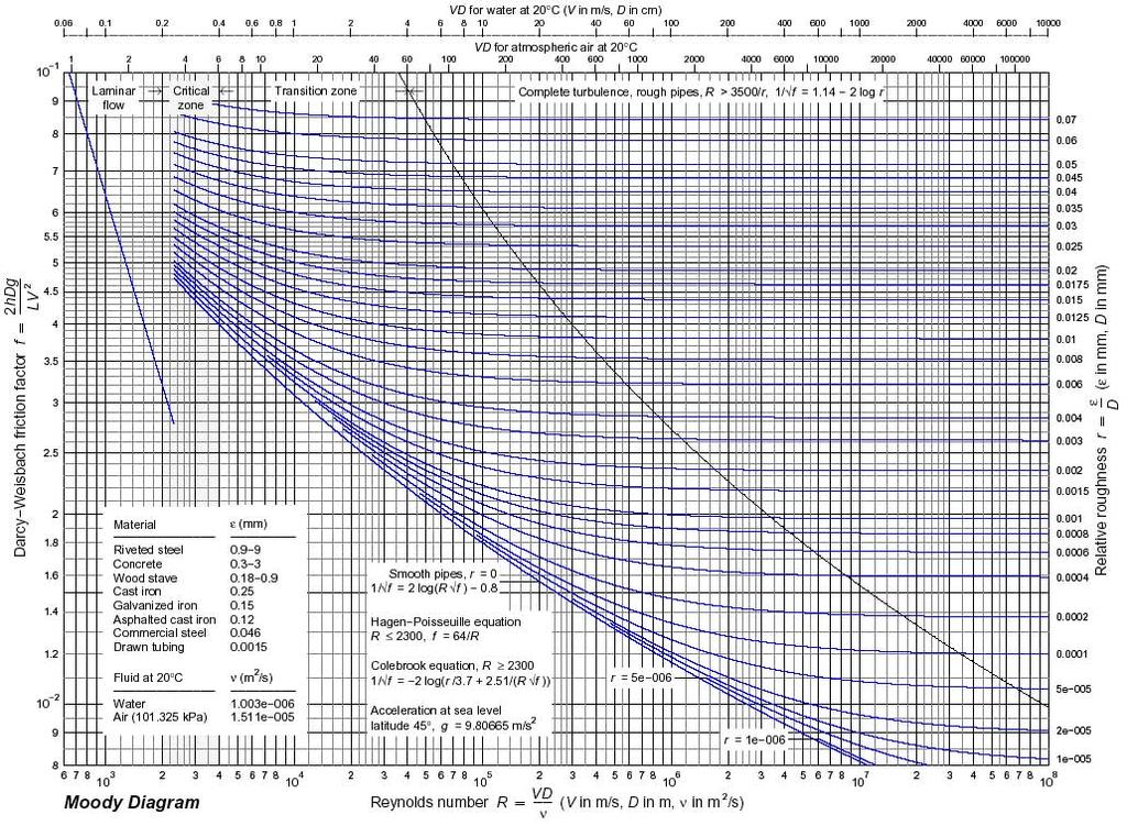
1 ME 333 Fluid Mechanics Lab Session VISCOUS LOSSES IN PIPES Introduction Flow in pipes, laminar or turbulent, is subject to pressure losses that result from the viscous stresses on the wall of the pipe. These losses are dependent on the Reynolds number of the flow and the surface roughness of the pipe wall. This phenomenon is described in terms of the friction factor (non dimensional pressure loss per unit length of the pipe) in Moody s diagram (See back of the handout). Losses resulting from complex flow patterns appearing at some elements of piping systems, such as valves, expansions, contractions, elbows, etc., can be described in similar terms by means of a concentrated loss given by a non dimensional loss factor K. Objectives The objective of this lab session is to experimentally measure the pressure losses along a section of pipe containing a 90 turn, for different values of the Reynolds number. The different losses associated with different elements will be studied by measuring the pressure loss with a round elbow in the system and with a capped T fitting, which simulates a 90 sharp corner. This fitting can be positioned in two different ways, both of which will be measured. Experimental Procedure Before you begin the experiment make sure you understand the experimental setup, the instruments you are going to use in the measurements and what you need to do in order to carry out the experiment. Look at figure 1 and identify the different elements in the actual experiment. Follow the procedure: 1. Make sure the gate and ball valve under the table are fully open. 2. Turn on the system (main switch and manometer) and allow the system to warm up with the round elbow in the system. During this time, measure and record on your lab notebook: - barometric pressure - inside diameters of the pipe, elbow and capped T - distance between adjacent taps along pipe A, as well as the distance l 1 and l 2, defined in figure Leave the ball valve open in pipe A (valve A) and make sure the ball valve in pipe B (valve B) is fully closed. Adjust the flow rate with the gate valve under the table. The
2 flow rate is measured by the laminar flow meter and the inclined manometer (in mm H 2 O). Start the experiment by closing the ball valve under the table (bleeding air) and setting a flow rate of 50 mm H 2 O. Record the overall pressure drop between points 1 and 2 at the beginning and the end of the pipe loop. The reading from the electronic manometer is in mm Hg. Record also the temperature in the flow from the electronic display of the thermocouple unit. 4. Set the reference in the electronic manometer to the pressure at point R 1 and record the readings of the pressure drop between the different stations, 2 through 11, and the reference R Repeat steps 3 and 4, setting the flow rate to 20 mm H 2 O (open the ball valve under the table to bleed some air before closing the gate valve to reduce the flow rate. You don t want to choke the compressor.) 6. Repeat steps 3 to 5 replacing the round elbow with the capped T in both configurations showed in figure 1, T 1 and T 2. Measure the pressure drop in both configurations for the two different flow rates, 50 and 20 mm H 2 O. 7. When you are finished, turn of the power and leave everything as you found it.
3 Report Each group will present a single report with all the data and analysis. You can split the work but you are all expected to know what is in the report and to understand it well enough to explain it to others as if you had done it. Plot the pressure drop measurements as a function of linear distance from the reference R 1 for the different experimental conditions. Consider the elbow as a concentrated loss (that is of zero length). The distance between station 7 and 6 will then be just l 1 +l 2. Use a minimum squares fit to the data, together with equation 6.10 from White s Intro to Fluids book, 7 th Ed., or equivalent from Smits book, to calculate the friction factor in the pipe. Use the six independent measurements for the same flow rate to estimate the error. You can use Moody s diagram or equation 6.48 from White s Intro to Fluids book, 7 th Ed., or equivalent from Smits book) to calculate the roughness of the aluminum pipe. The pressure loss at the elbow can be measured from the jump between stations 6 and 7, discounting the loss due to the lengths l 1 and l 2. The expression to calculate the loss factor can be found in equation 6.74 from White s Intro to Fluids book, 7 th Ed., or equivalent from Smits book. You should estimate which measurements are more accurate and what are the sources of error. This is an important part of the report, not a little afterthought. The report should consists at the least of the following sections: Introduction Experimental setup Results (Raw data and calculations) Discussion Conclusions References You can include Appendices with any information you think is relevant but would not fit well in the other sections of the report, or would it make it difficult to read because is too lengthy or includes too much detail.
4
5
MEMORIAL UNIVERSITY OF NEWFOUNDLAND Faculty of Engineering and Applied Science FLUID MECHANICS LABORATORY PIPE FRICTION
 MEMORIAL UNIVERSITY OF NEWFOUNDLAND Faculty of Engineering and Applied Science FLUID MECHANICS LABORATORY PIPE FRICTION Objective To estimate the fluid pressure drops and roughness specifications for copper
Experiment 8: Minor Losses
 Experiment 8: Minor Losses Purpose: To determine the loss factors for flow through a range of pipe fittings including bends, a contraction, an enlargement and a gate-valve. Introduction: Energy losses
Lab #4 Pipe Flow, Minor and Major Losses, and Walking in Osborne Reynolds Shoes CEE 331 Fall 2006
 CEE 331 Lab 4 Page 1 of 5 Lab #4 Pipe Flow, Minor and Major Losses, and Walking in Osborne Reynolds Shoes CEE 331 Fall 2006 Safety The major safety hazard in this laboratory is a shock hazard. Given that
Cover Page for Lab Report Group Portion. Head Losses in Pipes
 Cover Page for Lab Report Group Portion Head Losses in Pipes Prepared by Professor J. M. Cimbala, Penn State University Latest revision: 02 February 2012 Name 1: Name 2: Name 3: [Name 4: ] Date: Section
Lab 1c Isentropic Blow-down Process and Discharge Coefficient
 058:080 Experimental Engineering Lab 1c Isentropic Blow-down Process and Discharge Coefficient OBJECTIVES - To study the transient discharge of a rigid pressurized tank; To determine the discharge coefficients
Cover Page for Lab Report Group Portion. Drag on Spheres
 Cover Page for Lab Report Group Portion Drag on Spheres Prepared by Professor J. M. Cimbala, Penn State University Latest revision: 29 September 2017 Name 1: Name 2: Name 3: [Name 4: ] Date: Section number:
H16 Losses in Piping Systems
 H16 Losses in Piping Systems The equipment described in this manual is manufactured and distributed by TECQUIPMENT LIMITED Suppliers of technological laboratory equipment designed for teaching. BONSALL
RESIDENTIAL WATER DISTRIBUTION
 RESIDENTIAL WATER DISTRIBUTION This case study demonstrates the steady-state simulation of the fresh water (drinking water) reticulation system in a small village. WATER RETICULATION Page1 WATER RETICULATION
Heat Pump Connections and Interior Piping
 Job Sheet 3 Heat Pump Connections and Interior Piping OBJECTIVES In this job sheet, you will observe how the presence of air in the ground loop affects the geothermal heat pump performance. You will also
485 Annubar Primary Flow Element Installation Effects
 ROSEMOUNT 485 ANNUBAR 485 Annubar Primary Flow Element Installation Effects CONTENTS Mounting hole diameter Alignment error Piping Geometry Induced Flow Disturbances Pipe reducers and expansions Control
Measurement And Control Appreciation
 Measurement And Control Appreciation Course Content Aim To provide an appreciation of the operation and application of process plant instrumentation used for the measurement and display of the main process
Avai 193 Fall 2016 Laboratory Greensheet
 Avai 193 Fall 2016 Laboratory Greensheet Lab Report 1 Title: Instrumentation Test Technique Research Process: Break into groups of 4 people. These groups will be the same for all of the experiments performed
The Discussion of this exercise covers the following points:
 Exercise 5-3 Wet Reference Leg EXERCISE OBJECTIVE Learn to measure the level in a vessel using a wet reference leg. DISCUSSION OUTLINE The Discussion of this exercise covers the following points: Measuring
Applied Fluid Mechanics
 Applied Fluid Mechanics 1. The Nature of Fluid and the Study of Fluid Mechanics 2. Viscosity of Fluid 3. Pressure Measurement 4. Forces Due to Static Fluid 5. Buoyancy and Stability 6. Flow of Fluid and
Fluid Flow. Link. Flow» P 1 P 2 Figure 1. Flow Model
 Fluid Flow Equipment: Water reservoir, output tubes of various dimensions (length, diameter), beaker, electronic scale for each table. Computer and Logger Pro software. Lots of ice.temperature probe on
Instruction Manual. Pipe Friction Training Panel
 Instruction Manual HL 102 Pipe Friction Training Panel 100 90 80 70 60 50 40 30 20 10 HL 102 Instruction Manual This manual must be kept by the unit. Before operating the unit: - Read this manual. - All
Cover Page for Lab Report Group Portion. Compressible Flow in a Converging-Diverging Nozzle
 Cover Page for Lab Report Group Portion Compressible Flow in a Converging-Diverging Nozzle Prepared by Professor J. M. Cimbala, Penn State University Latest revision: 13 January 2012 Name 1: Name 2: Name
Cover Page for Lab Report Group Portion. Pump Performance
 Cover Page for Lab Report Group Portion Pump Performance Prepared by Professor J. M. Cimbala, Penn State University Latest revision: 02 March 2012 Name 1: Name 2: Name 3: [Name 4: ] Date: Section number:
MEMORANDUM. Investigation of Variability of Bourdon Gauge Sets in the Chemical Engineering Transport Laboratory
 1 MEMORANDUM TO: FROM: Prof. Davis Hubbard Prof. Faith A. Morrison DATE: 22 April 2014 RE: Investigation of Variability of Bourdon Gauge Sets in the Chemical Engineering Transport Laboratory Introduction
Successful completion of the course leads to the award of the Technical Training Solutions Certificate of Competence 510: Instrumentation.
 INSTRUMENTATION COURSE 510: 3 DAYS: Max 8 Candidates This course covers the key aspects of industrial instrumentation and is designed to enable maintenance personnel to carry out commissioning, calibration
Experimental Investigation Of Flow Past A Rough Surfaced Cylinder
 (AET- 29th March 214) RESEARCH ARTICLE OPEN ACCESS Experimental Investigation Of Flow Past A Rough Surfaced Cylinder Monalisa Mallick 1, A. Kumar 2 1 (Department of Civil Engineering, National Institute
Micro Motion Pressure Drop Testing
 12/2018 Micro Motion Pressure Drop Testing www.emerson.com/micromotion Introduction Micro Motion has traditionally taken a very conservative approach to pressure drop, with single pressure measurements
The Discussion of this exercise covers the following points:
 Exercise 3-2 Orifice Plates EXERCISE OBJECTIVE In this exercise, you will study how differential pressure flowmeters operate. You will describe the relationship between the flow rate and the pressure drop
Cover Page for Lab Report Group Portion. Lift on a Wing
 Cover Page for Lab Report Group Portion Lift on a Wing Prepared by Professor J. M. Cimbala, Penn State University Latest revision: 17 January 2017 Name 1: Name 2: Name 3: [Name 4: ] Date: Section number:
MANUAL FLOW CONTROL 2-1/2" - 18" QUICKSET FLOW CHART
 This chart performs two functions: It allows you to calculate the permanent pressure drop for any size Quickset or. This figure is useful mostly in the design process, for system calculations. It allows
CONTROL and INSTRUMENTATION
 CONTROL and INSTRUMENTATION COURSE 500: 5 DAYS: Max 8 Candidates This course covers the key aspects of current instrumentation and process control technology and is designed to enable maintenance personnel
CHAPTER 2 EXPERIMENTAL SETUP AND PROCEDURE
 22 CHAPTER 2 EXPERIMENTAL SETUP AND PROCEDURE 2.1 EXPERIMENTAL COLUMN All the experiments were carried out in an internal loop airlift fluidized bed and combined loop fluidized bed (an external down comer
Cover Page for Lab Report Group Portion. Compressible Flow in a Converging-Diverging Nozzle
 Cover Page for Lab Report Group Portion Compressible Flow in a Converging-Diverging Nozzle Prepared by Professor J. M. Cimbala, Penn State University Latest revision: Prof. Steve Lynch, 14 February 2017
****** * EX * ****** DWN W.W.POWELL CALCULATION OF FLOW LOSSES IN INLET CHK D.PAPA AND DISCHARGE HEADERS ASSOCIATED WITH
 BC ****** * EX * ****** DWN W.W.POWELL 4-17-75 CALCULATION OF FLOW LOSSES IN INLET CHK D.PAPA 4-17-75 AND DISCHARGE HEADERS ASSOCIATED WITH APPR APPR SAFETY RELIEF VALVES SIZE REV APPR A 02.0175.128 L
Hours / 100 Marks Seat No.
 17421 21415 3 Hours / 100 Marks Seat No. Instructions : (1) All Questions are compulsory. (2) Answer each next main Question on a new page. (3) Illustrate your answers with neat sketches wherever necessary.
Exercise 2-2. Second-Order Interacting Processes EXERCISE OBJECTIVE DISCUSSION OUTLINE. The actual setup DISCUSSION
 Exercise 2-2 Second-Order Interacting Processes EXERCISE OBJECTIVE Familiarize yourself with second-order interacting processes and experiment with the finer points of controller tuning to gain a deeper
COMPUTATIONAL FLOW MODEL OF WESTFALL'S LEADING TAB FLOW CONDITIONER AGM-09-R-08 Rev. B. By Kimbal A. Hall, PE
 COMPUTATIONAL FLOW MODEL OF WESTFALL'S LEADING TAB FLOW CONDITIONER AGM-09-R-08 Rev. B By Kimbal A. Hall, PE Submitted to: WESTFALL MANUFACTURING COMPANY September 2009 ALDEN RESEARCH LABORATORY, INC.
PIG MOTION AND DYNAMICS IN COMPLEX GAS NETWORKS. Dr Aidan O Donoghue, Pipeline Research Limited, Glasgow
 PIG MOTION AND DYNAMICS IN COMPLEX GAS NETWORKS Dr Aidan O Donoghue, Pipeline Research Limited, Glasgow A model to examine pigging and inspection of gas networks with multiple pipelines, connections and
By Syed Ahmed Amin Shah 4 th semester Class No 8 Submitted To Engr. Saeed Ahmed
 EXPERIMENT # 01 DEMONSTRATION OF VARIOUS PARTS OF HYDRAULIC BENCH. HYDRAULIC BENCH Hydraulic bench is a very useful apparatus in hydraulics and fluid mechanics it is involved in majority of experiments
UNIVERSITY OF WATERLOO
 UNIVERSITY OF WATERLOO Department of Chemical Engineering ChE 524 Process Control Laboratory Instruction Manual January, 2001 Revised: May, 2009 1 Experiment # 2 - Double Pipe Heat Exchanger Experimental
Lab Problems. Lab Problems for Chapter Fluid Characterization by Use of a Stormer Viscometer L-1
 Lab Problems This section contains end-of-the-chapter problems that involve data obtained from various simple laboratory experiments. These lab problems for any chapter can be obtained by clicking on the
Study on the Influencing Factors of Gas Mixing Length in Nitrogen Displacement of Gas Pipeline Kun Huang 1,a Yan Xian 2,b Kunrong Shen 3,c
 Applied Mechanics and Materials Online: 2013-06-13 ISSN: 1662-7482, Vols. 321-324, pp 299-304 doi:10.4028/www.scientific.net/amm.321-324.299 2013 Trans Tech Publications, Switzerland Study on the Influencing
Design of a Solid Wall Transonic Wind Tunnel
 Design of a Solid Wall Transonic Wind Tunnel David Wall * Auburn University, Auburn, Alabama, 36849 A solid wall transonic wind tunnel was designed with optical access from three sides to allow for flow
Pressure Measurement
 Pressure Measurement Manometers Sensors, Transducers Ashish J. Modi Lecturer, Dept. of Mech.Engg., Shri S.V.M. inst. Of Technology, Bharuch Pressure Pressure is a force per unit area exerted by a fluid
Lab. Manual. Fluid Mechanics. The Department of Civil and Architectural Engineering
 Lab. Manual of Fluid Mechanics The Department of Civil and Architectural Engineering General Safety rules to be followed in Fluid Mechanics Lab: 1. Always wear shoes before entering lab. 2. Do not touch
Instructions for SMV 3000 Multivariable Configuration (MC) Data Sheets
 Data Sheets") Instructions for SMV 3000 Multivariable Configuration (MC) Data Sheets Similar to the TC option for ST 3000 transmitters, the MC option for the SMV 3000 provides a service to our customers which results
Instructions for SMV 3000 Multivariable Configuration (MC) Data Sheets Similar to the TC option for ST 3000 transmitters, the MC option for the SMV 3000 provides a service to our customers which results
Introductory Lab: Vacuum Methods
 Introductory Lab: Vacuum Methods Experiments in Modern Physics (P451) In this lab you will become familiar with the various components of the lab vacuum system. There are many books on this topic one of
Mass Split of Two-Phase-Flow
 Mass Split of Two-Phase-Flow The split of two-phase-flow at horizontal side-t-junctions in unbalanced pipe systems for clean extinguishing agents Speaker: Gudrun Fay Minimax 2010 2013 Content 1. Applications
Paper 2.2. Operation of Ultrasonic Flow Meters at Conditions Different Than Their Calibration
 Paper 2.2 Operation of Ultrasonic Flow Meters at Conditions Different Than Their Calibration Mr William Freund, Daniel Measurement and Control Mr Klaus Zanker, Daniel Measurement and Control Mr Dale Goodson,
CFD Flow Analysis of a Refrigerant inside Adiabatic Capillary Tube
 CFD Flow Analysis of a Refrigerant inside Adiabatic Capillary Tube Y Raja Kumar ¹, Dr.P Usha sri ² PG Student¹, Associate professor² Department of Mechanical Engineering, University College of Engineering
and its weight (in newtons) when located on a planet with an acceleration of gravity equal to 4.0 ft/s 2.
 when located on a planet with an acceleration of gravity equal to 4.0 ft/s 2.") 1.26. A certain object weighs 300 N at the earth's surface. Determine the mass of the object (in kilograms) and its weight (in newtons) when located on a planet with an acceleration of gravity equal to
1.26. A certain object weighs 300 N at the earth's surface. Determine the mass of the object (in kilograms) and its weight (in newtons) when located on a planet with an acceleration of gravity equal to
Development of Gasdynamic Probe for Total Temperature Measurement in gases
 ASET 20- National Conference on Emerging Trends in Propulsion Technology Development of Gasdynamic Probe for Total Temperature Measurement in gases K Sathiyamoorthy, Souren Misra 2, Srinivas J, Baskaran
Experiment 12: MOLAR VOLUME OF AN IDEAL GAS
 Experiment 1: MOLAR VOLUME OF AN IDEAL GAS Purpose: Determine the molar volume of a gas at standard temperature and pressure (STP, 0 C and pressure of 1 atm) Performance Goals: Collect and measure the
Purdue e-pubs. Purdue University. Stephan Lehr Technische Universitaet Dresden. Follow this and additional works at:
 Purdue University Purdue e-pubs International Compressor Engineering Conference School of Mechanical Engineering 21 Numerical Investigation Of The Influence Of The Transient Flow Inside the Suction And
Experiment Instructions. Circulating Pumps Training Panel
 Experiment Instructions Circulating Pumps Training Panel Experiment Instructions This manual must be kept by the unit. Before operating the unit: - Read this manual. - All participants must be instructed
Physical Analysis Model Report
 Physical Analysis Model Report Developed by The University of Kentucky and KYPIPE LLC Prepared for the National Institute of Hometown Security 368 N. Hwy 27 Somerset, KY 42503 November 19, 2012 This research
BY THOMAS M. WALSKI, BRIAN LUBENOW, AND JEFFREY SPAIDE. When they install a branch from a water distribution main,
 BY THOMAS M. WALSKI, BRIAN LUBENOW, AND JEFFREY SPAIDE When they install a branch from a water distribution main, water utility managers often debate the benefits of using a tap as opposed to shutting
Appendix D: SOP of INNOVA 1412 Photoacoustic Multi-Gas Monitor. Description and Principle of Operation
 Page 1 of 19 : SOP of INNOVA 1412 Photoacoustic Multi-Gas Monitor Description and Principle of Operation The photoacoustic multi-gas monitor (INNOVA 1412, Innova AirTech Instruments, Denmark) is a highly
DARSHAN INSTITUTE OF ENGINEERING AND TECHNOLOGY
 DARSHAN INSTITUTE OF ENGINEERING AND TECHNOLOGY FLUID MECHANICS (2141906) INDEX Sr. No. 1. 2. 3. 4. Experiment Start Date End Date Sign Grade To validate Bernoulli s theorem as applied to the flow of water
WHITE PAPER. SmartPlant P&ID Engineering Integrity 10 Example Rules
 WHITE PAPER SmartPlant P&ID Engineering Integrity 10 Example Rules SmartPlant P&ID Engineering Integrity SmartPlant P&ID Engineering Integrity checks that SmartPlant P&IDs comply with engineering standards
Experimental study for flow characteristics and performance evaluation of butterfly valves
 IOP Conference Series: Earth and Environmental Science Experimental study for flow characteristics and performance evaluation of butterfly valves To cite this article: C K Kim et al 2010 IOP Conf. Ser.:
Lesson 12: Fluid statics, Continuity equation (Sections ) Chapter 9 Fluids
 Chapter 9 Fluids") Lesson : luid statics, Continuity equation (Sections 9.-9.7) Chapter 9 luids States of Matter - Solid, liquid, gas. luids (liquids and gases) do not hold their shapes. In many cases we can think of liquids
Lesson : luid statics, Continuity equation (Sections 9.-9.7) Chapter 9 luids States of Matter - Solid, liquid, gas. luids (liquids and gases) do not hold their shapes. In many cases we can think of liquids
Lab # 03: Visualization of Shock Waves by using Schlieren Technique
 AerE545 Lab # 03: Visualization of Shock Waves by using Schlieren Technique Objectives: 1. To get hands-on experiences about Schlieren technique for flow visualization. 2. To learn how to do the optics
International Journal of Research in Advent Technology Available Online at:
 Volume, Issue 5, December 23 AN APPROACH TO DEVELOPMENT OF AIR LEAKAGE TEST RIG FOR AIR HANDLING UNITS HOUSING. Deepak Singh Asst. Professor, Department of Mechanical Engineering Kautilya Institute of
Numerical Simulations of a Train of Air Bubbles Rising Through Stagnant Water
 Numerical Simulations of a Train of Air Bubbles Rising Through Stagnant Water Hong Xu, Chokri Guetari ANSYS INC. Abstract Transient numerical simulations of the rise of a train of gas bubbles in a liquid
Wind Flow Model of Area Surrounding the Case Western Reserve University Wind Turbine
 Wind Flow Model of Area Surrounding the Case Western Reserve University Wind Turbine Matheus C. Fernandes 1, David H. Matthiesen PhD *2 1 Case Western Reserve University Dept. of Mechanical Engineering,
Hydrogen Bubble Flow Visualization Unit UVF
 Technical Teaching Equipment Hydrogen Bubble Flow Visualization Unit UVF PROCESS DIAGRAM AND UNIT ELEMENTS ALLOCATION ISO 9001: Quality Management (for Design, Manufacturing, Commercialization and After-sales
METHOD 2E - DETERMINATION OF LANDFILL GAS PRODUCTION FLOW RATE. NOTE: This method does not include all of the
 287 METHOD 2E - DETERMINATION OF LANDFILL GAS PRODUCTION FLOW RATE NOTE: This method does not include all of the specifications (e.g., equipment and supplies) and procedures (e.g., sampling and analytical)
MODELING AND SIMULATION OF VALVE COEFFICIENTS AND CAVITATION CHARACTERISTICS IN A BALL VALVE
 Proceedings of the 37 th International & 4 th National Conference on Fluid Mechanics and Fluid Power FMFP2010 December 16-18, 2010, IIT Madras, Chennai, India FMFP2010 341 MODELING AND SIMULATION OF VALVE
Laboratory Experiments No 1: Measuring the Number Distribution
 Laboratory Experiments No 1: Measuring the Number Distribution Purpose: To test the operation of the DMA by comparing the calculated size to a monodisperse aerosol particle, and to use the DMA to measure
DEVICES FOR FIELD DETERMINATION OF WATER VAPOR IN NATURAL GAS Betsy Murphy MNM Enterprises 801 N. Riverside Drive Fort Worth, Texas 76111
 INTRODUCTION Water vapor in natural gas has more than a substantial effect on the quality of the gas stream. Without quality measurement of water vapor the gas is basically not saleable. Contracts are
CYCLE ANALYSIS OF LINEAR COMPRESSORS USING THREE- DIMENSIONAL CFD
 CYCLE ANALYSIS OF LINEAR COMPRESSORS USING THREE- DIMENSIONAL CFD I. Y. An and Y. L. Lee Department of Mechanical Engineering, Kongju National University, Korea E-Mail: ylee@kongju.ac.kr ABSTRACT In order
International Journal of Technical Research and Applications e-issn: , Volume 4, Issue 3 (May-June, 2016), PP.
, PP.") DESIGN AND ANALYSIS OF FEED CHECK VALVE AS CONTROL VALVE USING CFD SOFTWARE R.Nikhil M.Tech Student Industrial & Production Engineering National Institute of Engineering Mysuru, Karnataka, India -570008
DESIGN AND ANALYSIS OF FEED CHECK VALVE AS CONTROL VALVE USING CFD SOFTWARE R.Nikhil M.Tech Student Industrial & Production Engineering National Institute of Engineering Mysuru, Karnataka, India -570008
Assistant Lecturer Anees Kadhum AL Saadi
 Pressure Variation with Depth Pressure in a static fluid does not change in the horizontal direction as the horizontal forces balance each other out. However, pressure in a static fluid does change with
TWO PHASE FLOW METER UTILIZING A SLOTTED PLATE. Acadiana Flow Measurement Society
 TWO PHASE FLOW METER UTILIZING A SLOTTED PLATE Acadiana Flow Measurement Society Gerald L. Morrison Presented by: Mechanical Engineering Department Daniel J. Rudroff 323 Texas A&M University Flowline Meters
Lift for a Finite Wing. all real wings are finite in span (airfoils are considered as infinite in the span)
") Lift for a Finite Wing all real wings are finite in span (airfoils are considered as infinite in the span) The lift coefficient differs from that of an airfoil because there are strong vortices produced
Lift for a Finite Wing all real wings are finite in span (airfoils are considered as infinite in the span) The lift coefficient differs from that of an airfoil because there are strong vortices produced
The water supply for a hydroelectric plant is a reservoir with a large surface area. An outlet pipe takes the water to a turbine.
 Fluids 1a. [1 mark] The water supply for a hydroelectric plant is a reservoir with a large surface area. An outlet pipe takes the water to a turbine. State the difference in terms of the velocity of the
Greenup Lock Filling and Emptying System Study
 Fourth LACCEI International Latin American and Caribbean Conference for Engineering and Technology (LACCET 2006) Breaking Frontiers and Barriers in Engineering: Education, Research and Practice 21-23 June
VAPOR PRESSURE AND ENTHALPY OF VAPORIZATION OF A PURE LIQUID: THE ISOTENISCOPE METHOD
 Physical Chemistry Laboratory Experiment I-3b VAPOR PRESSURE AND ENTHALPY OF VAPORIZATION OF A PURE LIQUID: THE ISOTENISCOPE METHOD References: See relevant sections of undergraduate Physical Chemistry
Unit 2 Kinetic Theory, Heat, and Thermodynamics: 2.A.1 Problems Temperature and Heat Sections of your book.
 Unit 2 Kinetic Theory, Heat, and Thermodynamics: 2.A.1 Problems Temperature and Heat Sections 10.1 10.2 of your book. Convert the following to Celsius and Kelvin temperatures: 1. 80.0 o F Early E. C.:
Simple Measurements & Buoyancy Force
 Simple Measurements & Buoyancy Force 1 st year physics laboratories University of Ottawa https://uottawa.brightspace.com/d2l/home SIMPLE MEASUREMENTS The TA will go over the following tutorials. Error
Exercise 5-2. Bubblers EXERCISE OBJECTIVE DISCUSSION OUTLINE. Bubblers DISCUSSION. Learn to measure the level in a vessel using a bubbler.
 Exercise 5-2 Bubblers EXERCISE OBJECTIVE Learn to measure the level in a vessel using a bubbler. DISCUSSION OUTLINE The Discussion of this exercise covers the following points: Bubblers How to measure
HYDRAULICS. H89.8D - Hydraulic Bench
 HYDRAULICS H89.8D - Hydraulic Bench 1. General The H89.8D and ancillary equipment have been developed to provide a comprehensive range of experiments in fluid mechanics. The bench is of robust construction
Lab 4: Root Locus Based Control Design
 Lab 4: Root Locus Based Control Design References: Franklin, Powell and Emami-Naeini. Feedback Control of Dynamic Systems, 3 rd ed. Addison-Wesley, Massachusetts: 1994. Ogata, Katsuhiko. Modern Control
Characterizing Flow Losses Occurring in Air Vents and Ejector Pins in High Pressure Die Castings
 This paper is subject to revision. Statements and opinions advanced in this paper or during presentation are the author s and are his/her responsibility, not the Association s. The paper has been edited
Air Demand in Free Flowing Gated Conduits
 Utah State University DigitalCommons@USU All Graduate Theses and Dissertations Graduate Studies 12-2008 Air Demand in Free Flowing Gated Conduits David Peter Oveson Utah State University Follow this and
The Estimation Of Compressor Performance Using A Theoretical Analysis Of The Gas Flow Through the Muffler Combined With Valve Motion
 Purdue University Purdue e-pubs International Compressor Engineering Conference School of Mechanical Engineering The Estimation Of Compressor Performance Using A Theoretical Analysis Of The Gas Flow Through
Ship Resistance and Propulsion Prof. Dr. P. Krishnankutty Ocean Department Indian Institute of Technology, Madras
 Ship Resistance and Propulsion Prof. Dr. P. Krishnankutty Ocean Department Indian Institute of Technology, Madras Lecture - 7 Air and Wind Resistance Dimensional Analysis I Coming back to the class, we
CHAPTER 6: PERMEABILITY MEASUREMENT
 CHAPTER 6: PERMEABILITY MEASUREMENT Objective To measure the permeability of rock samples using a gas permeameter and to apply Klinkenberg effect corrections to obtain the liquid permeability. Introduction
Digital Level Control One and Two Loops Proportional and Integral Control Single-Loop and Cascade Control
 Digital Level Control One and Two Loops Proportional and Integral Control Single-Loop and Cascade Control Introduction This experiment offers a look into the broad field of process control. This area of
STUDY OF SLUG CONTROL TECHNIQUES IN PIPELINE SYSTEMS
 STUDY OF SLUG CONTROL TECHNIQUES IN PIPELINE SYSTEMS JOSÉ L. A,VIDAL Petrobrás Research Center - CENPES/PDEP/TOOL Av.Horácio de Macedo 95- Cidade Universitária 191-915 -Rio de Janeiro-RJ E-mail:josearias@petrobras.com.br
Static Fluids. **All simulations and videos required for this package can be found on my website, here:
 DP Physics HL Static Fluids **All simulations and videos required for this package can be found on my website, here: http://ismackinsey.weebly.com/fluids-hl.html Fluids are substances that can flow, so
An Experimental Performance Study of Vortex Tube Refrigeration System
 An Experimental Performance Study of Vortex Tube Refrigeration System Sankar Ram T. Department Of Industrial Refrigeration and Cryogenics T. K. M. College of Engineering Karicode, Kollam, Kerala sankarram9@gmail.com
CFD Simulation and Experimental Validation of a Diaphragm Pressure Wave Generator
 CFD Simulation and Experimental Validation of a Diaphragm Pressure Wave Generator T. Huang 1, A. Caughley 2, R. Young 2 and V. Chamritski 1 1 HTS-110 Ltd Lower Hutt, New Zealand 2 Industrial Research Ltd
GAS SUPPLY DESIGN GUIDE
 GAS SUPPLY DESIGN GUIDE Natural Gas, Propane Gas, or Dual Fuel Fired Modulating, Condensing Boilers BENCHMARK Series Gas-Fired Boilers For models: BMK750 to BMK6000 Last Update: 06/20/2014 PR1 06/20/14
Applied Thermodynamics. Experiment_01_MT_234. Instructor: Mr. Adnan Qamar. Mechanical Engineering Department
 Applied Thermodynamics Experiment_01_MT_234 Instructor: Mr. Adnan Qamar Mechanical Engineering Department 1 Experiment No. 01: To test that Pressure is an intensive property. Apparatus: Nozzle Distribution
Long Win s Educational Facilities for Fluid Mechanics
 Since 1985 F luid mechanics is a science to study how fluids flow and how fluids act on objects. T he wind tunnel is a comprehensive, complete and substantial system for students to study fundamental and
Schedule of Requirements THERMODYNAMICS LABORATORY- CHEMICAL ENGINEERING DEPARTMENT
 S. No 1 Description Calorimeter The Unit should be designed for the accurate determination of the calorific value of liquid and solid hydrocarbons and other fuels. Specifications: A temperature-controlled
AC : ACCURATE CRYOCHAMBER FOR A SMALL LABORATORY WITH SMALL BUDGET
 AC 2007-1108: ACCURATE CRYOCHAMBER FOR A SMALL LABORATORY WITH SMALL BUDGET Matthew Braley, University of Idaho Paul Anderson, University of Idaho Tracey Windley, University of Idaho Kevin Buck, University
Experiment (13): Flow channel
: Flow channel") Experiment (13): Flow channel Introduction: An open channel is a duct in which the liquid flows with a free surface exposed to atmospheric pressure. Along the length of the duct, the pressure at the surface
Experiment (13): Flow channel Introduction: An open channel is a duct in which the liquid flows with a free surface exposed to atmospheric pressure. Along the length of the duct, the pressure at the surface
AC : A STUDENT PROJECT ON AIRFOIL PERFORMANCE
 AC 2007-78: A STUDENT PROJECT ON AIRFOIL PERFORMANCE John Matsson, Oral Roberts University O. JOHN E. MATSSON is an Associate Professor of Mechanical Engineering at Oral Roberts University in Tulsa, Oklahoma.
Introduction. Physics E-1a Expt 4a: Conservation of Momentum and Fall 2006 The Ballistic Pendulum
 Physics E-1a Expt 4a: Conservation of Momentum and Fall 2006 The Ballistic Pendulum Introduction Preparation: Before coming to lab, read this lab handout and the suggested reading in Giancoli (through
Gas Measurement Fundamentals Certification. Curriculum
 Gas Certification Institute, LLC P.O. Box 131525 Houston, Texas 77219-1525 281-598-7200 Phone 281-598-7199 Fax contact@gascertification.com www.gascertification.com Curriculum Copyright 2007-2012 Gas Certification
MTS Restan. Automatic System for Residual Stress Measurement by Hole-Drilling
 Automatic System for Residual Stress The MTS3000 - Restan system for measuring residual stresses Fully automatic drilling and acquisition process ensuring high repeatability High speed drilling (400,000
Applying Hooke s Law to Multiple Bungee Cords. Introduction
 Applying Hooke s Law to Multiple Bungee Cords Introduction Hooke s Law declares that the force exerted on a spring is proportional to the amount of stretch or compression on the spring, is always directed