387. Fellenius, B.H Sixty Years of dynamic testing and analysis of piles A retrospective. Keynote Lecture to the 10th International Conference
|
|
|
- Aubrey Richards
- 5 years ago
- Views:
Transcription
1 Fellenius, B.H Sixty Years of dynamic testing and analysis of piles A retrospective. Keynote Lecture to the 10th International Conference on Stress-wave Theory and Testing. June 27-29, 2018, San Diego, CA, 50 p.

2 Sixty Years of dynamic testing and analysis of piles A retrospective Bengt H. Fellenius June 29, th International Conference on Stress-wave Theory and Testing Methods For Deep Foundations June 27-29, 2018, San Diego, CA Proudly Sponsored By: The Pile Driving Contractors Association 1


3 (Capacity) What is Capacity? Slide by courtesy of Mohamad Hussein, GRL 2


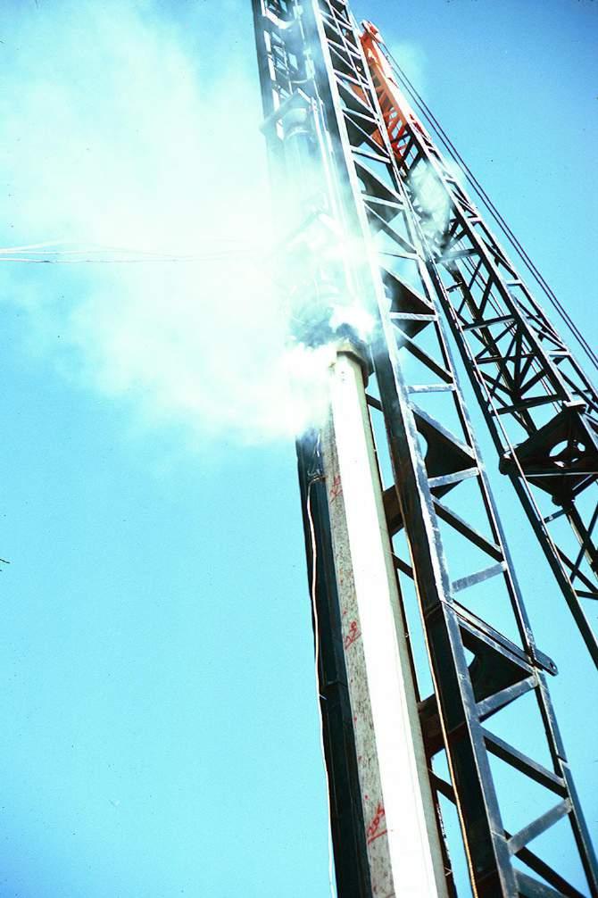
4 A project in the early 1970s illustrating that, despite the diminishing return of the blow-count demonstrated by the dynamic formulae, then, as now, stupidity prevails. To support the tower, the design required 23 steel H-piles driven to 85 ft depth. Soil profile and SPT N-diagram at a piled foundation for a power line tower in the middle of Alaska The drop hammer height-of-fall was raised to more than 10 ft! 3


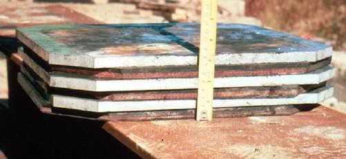
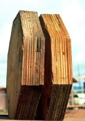
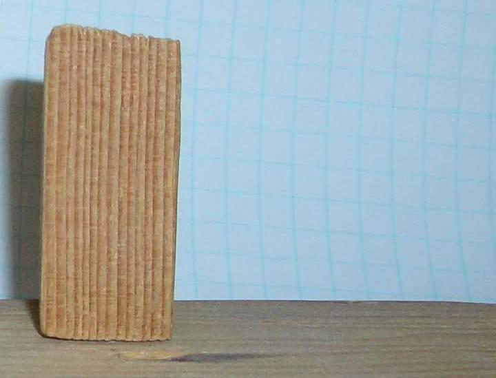
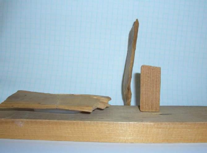
5 Another project at about the same time. Here the contractor had no problem getting the piles down to specified depth. The toe resistance was rather small toward the end, though. Side View Front View 4
6 The 1959 Gubbero Tests, Göteborg, Sweden Comparison of strain-waves from a pile driven with several different hammers. Nos. 1-4 are drop hammers (0.6, 0.8, 1.8, and 2.8 tonne) Nos. 5-6 are pneumatic hammers (Plt 290 K and M&H) Nos. 7-8 are diesel hammers (D12 and D22)

7 The 1959 Gubbero Tests, Göteborg, Sweden Stress-waves (strain) measured at the head of a 260 mm diameter, 75 m long concrete pile before and after cushion change. Two blows recorded from each event. 6
8 Stress-waves measured both at the pile head and at the pile toe. (Different hammers, different pile lengths, and different cushions, but travel time is the same) 7
9 Some small steps toward theoretical analysis were indeed made by man, but the main result of the 1959 Gubbero tests was the realization of the complexity of pile driving. Then, came the means to Analysis. E.A.L. Smith (1960) 8


10 Slide by courtesy of Mohamad Hussein, GRL 9

11 Tip-toeing through, missing the point 10

12 C.O.R = Coefficient of Restitution

13

14 Along with WEAP came the Pile Driving Analyzer, the PDA! Strain Gage Accelerometer PDA set-up in
15 With the break-through use of both strain-gages and accelerometers. Dynamic and Static Static Resistance includes adjustment by a damping factor The Case Method Estimate CMES-RSP 14

16 THE PIONEERS George Goble 1975 Photo courtesy of Pete Bentley 15

17 Frank Rausche 1975 Photo courtesy of Pete Bentley 16

18 Frank Rausche and Garland Likins Photo courtesy of Pete Bentley
19 A couple of wave-trace graphs from mid 1970s Initial Driving, EOID PRES 1 bl/in Restrike Driving, RSTR-1 BOR-1 PRES 3 bl/in 18
20 A project in Salt Lake City in late 1980 Piles (similar to Pile 1, below) were driven well, but then, suddenly, they could not be driven deeper than about 15 m (e.g. Pile 2, below). G.W. Loose to compact silt and clay. Hydrostatic pore water pressure to 14 m depth in closed-toe pipe piles driven with Delmag D30-32 Pile 1 = inch wall Pile 2 = inch wall 1 Very dense, 4 m thick layer capping pore pressures below Large artesian pore pressures below 16 m depth Did the pile driving hammer cease to work properly for the No. 2 piles? Or, was the difference in driving response between Piles 1 and 2 due to changed conditions? If the latter, the Contractor could recoup his costs. 19
21 Pile 1 (0.6 in) Impact Force Pile 2 (0.375 in) Impact Force The impact stress and stress-wave length were about the same for the piles, but the impact force is stress times area and the area was larger for Pile 1. Force is what moves a pile against the soil. 20

22 A project in Salt Lake City in late 1980 Piles (similar to Pile 1, below) were driven well, but then, suddenly, they could not be driven deeper than about 15 m (e.g. Pile 2, below). G.W. Loose to compact silt and clay. Hydrostatic pore water pressure to 14 m depth in closed-toe pipe piles driven with Delmag D30-32 Pile 1 = inch wall Pile 2 = inch wall Very dense, 4 m thick layer capping pore pressures below 1 Large artesian pore pressures below 16 m depth Repeated slide 21
23 DEPTH (m) DEPTH (m) DEPTH (m) DEPTH (m) Example 1 of a CPTU sounding from a river estuary delta (Nakdong River, Pusan, Korea) 0 Cone Stress, q t (MPa) Sleeve Friction (KPa) Pore Pressure (KPa) Friction Ratio (%) CLAY 5 CLAY 5 5 CLAY SILT SILT SILT SAND SAND SAND CPTU diagrams from a sounding in non-dilatant sand 22
 0 250 500 750 1,000 0 Friction Ratio (%) 0 1 2 3 4 5 0 Profile 10 10 10 10 Mixed Y 20 20 20 20 CLAY 30 30 30 30 40 40 40 40 SAND SAN D 50 50 50 50 The sand layer between 6 m and 8")
24 DEPTH (m) DEPTH (m) DEPTH (m) DEPTH (m) Example 2 of a CPTU sounding from a river estuary delta (Nakdong River, Pusan, Korea) 0 Cone Stress, q t (MPa) Sleeve Friction (KPa) Pore Pressure (KPa) ,000 0 Friction Ratio (%) Profile Mixed Y CLAY SAND SAN D The sand layer between 6 m and 8 m depth is potentially liquefiable. The clay layer is very soft. The sand below 34 m depth is very dense and dilatant, i.e., overconsolidated and providing sudden large penetration resistance to driven piles and relaxation problems. 23
25 DEPTH (m) DEPTH (m) DEPTH DEPTH (m) (m) DEPTH (m) DEPTH (m) DEPTH (m) DEPTH (m) DEPTH (m) DEPTH (m) DEPTH (m) DEPTH (m) DEPTH (m) DEPTH (m) DEPTH (m) DEPTH (m) DEPTH (m) Driving a 600 mm diameter, 45 m long, closed-toe, cylinder pile at the site PRES (blows/metre) The Pile that Ate Its Toe! Portion of PRES (blows/metre) Driving stopped because the CPTU Termination Resistance U2-diagram had been reached. Ten CLAY minutes after EOD, the 30 pile sunk 30 2 m! Driving stopped because Termination Resistance had been reached. Ten minutes after EOD, the pile sunk 30 2 m! 40 Pile is broken and the resumed driving was essentially just crushing concrete. Pile is broken and the resumed driving was essentially just crushing concrete. and driving the toe up into the cylinder void We continued driving u 0 SAN D 30 U2 40 CLAY SAN D CLAY SAN D CLAY SAN D
26 Force (KN) Force (KN) Force (KN) Force (KN) Wave Traces from the event Three blows before the event occurred First blow after the event 5,000 4,000 Blow 216 Depth 32.6m 5,000 4,000 Blow 219 Depth 34.2m 3,000 3,000 2,000 1, ,000-2,000 Force Velocity TIME (L/c) 2,000 1, ,000-2,000 Force Velocity TIME (L/c) 5,000 4,000 Blow 216 5,000 4,000 Blow 219 3,000 3,000 2,000 2,000 1,000 1, ,000-1,000-2,000-3,000 Wave Up Wave Down TIME (L/c) -2,000-3,000 Wave Up Wave Up TIME (L/c) 25
27 C A P W A P Analysis Force-match and Velocity match (Hannigan 1990) 26

28 C A P W A P Analysis Process 0 L/c 2 L/c Example of force-match iterations (Hannigan 1990) 27

29 Back in the early days, we all wondered (1) how true was the CAPWAP-determined capacity to that determined from a static loading test and (2) how consistent would the capacities be between analyses performed by different operators? STATIC TEST CAPWAP Operator ID # Compilation of CAPWAPs by different operators AM site (Fellenius 1988) 28
")
30 Compilation of CAPWAPs by different operators JI site (Fellenius 1988) 29
31 Resistance Distribution Compilation of CAPWAPs by different operators JI site (Fellenius 1988) 30
32 Q U A K E! CASE 2 CASE 2 Easy Driving at 11.3 m depth Easy Driving at 11.3 m depth Wave traces from one of twentyfour 305 mm square, precast concrete piles were driven through about 11 m of clay deposit into dense clayey silty glacial till. End of Driving at 12.5 m depth 1st Stress-wave Conference; Authier and Fellenius (1980), reporting analysis produced by Frank Rausche, GRL. 31
33 CAPWAP Matches CASE 2 CASE CASE 22 Easy Driving at at 11.3 m depth End End of of Driving Driving at at m depth depth 1st Stress-wave Conference; Authier and Fellenius (1980), reporting analysis produced by Frank Rausche, GRL. 32
34 Bearing Graphs from WEAP Simulations assuming different quake magnitudes 1st Stress-wave Conference; Fellenius and Authier (1980) 33

35 Not shown: the 9 th Kanazawa
36 Dynamic and static tests on a 20-inch diameter, 41 m long prestressed pile driven for Alesea Bay Bridge foundations CAPWAP-determined capacity was 3,600 kn, but static loading test gave 8,000+ kn. Yet, I consider the two tests to agree perfectly. At PILE HEAD CAPWAP Distribution Load-movement plotted in sequence of testing Static Test Distribution 6 mm 45 mm Toe Response Load distribution Toe load-movement response Fellenius and Riker,
37 DEPTH (m) (m) Design of a piled foundation LNG facility involving 1,000, 120 ft long, 24-inch prestressed piles 00 2,000 4,000 4,000 6,000 6,000 8,000 8,000 10,000 10, CAPACITY (kn) (kn) Capacity from SPT Capacity N-indices from SPT N-indices CAPWAP Capacities of test piles at EOID Most construction piles "came-in-short". End-of- Initial-Driving, Beta = 0.10 and EOID, 0.25dynamic tests N t = were 10 and performed 25 on a few of these Beta = 0.20 and 0.25 N t = 30 and Depth per design Depth per design Required Capacity = Allowable Load, 1,600 kn, CAPWAP times 2.5Capacities of 'deeper' test piles at EOID At End-of-Driving, EOD, the construction piles had been hammered in excess of 100 bl/ft for several feet! 36
38 DEPTH (m) Of course, set-up was considered to be just an additional conservative benefit. PRES (bl/0.3m) CMES RX6 (kn) ,000 2,000 3,000 4,000 5,000 6, Prebored Depth Allowable Load Required Capacity for F s = Initial Driving Resumed Driving CAPWAP Capacity Time between EOID and Resumed Driving = 7 days You can lead the horse to water...!
39 LOAD (KN) Also the best field work can get messed up if the analysis and conclusion effort loses sight of the history of the data 2,000 1,500 DYNAMIC TEST DYNAMIC TEST in a DYNAMIC series of TEST blows STATIC TEST Repeated STATIC TEST 1, MOVEMENT (mm) The dynamic test (CAPWAP) was performed after the static test. The redriving (ten blows) forced the pile down additionally about 45 mm. 38
40 Plugging of an Open-toe Pipe Pile Forces on pipe in dynamic and static loading Forces and Movement of the core in static loading (The pipe is not shown) Core Core Core Core Movement between core and inside of pipe In Driving, the pipe and core are fully mobilized In a Static Test the core is only partially mobilized The core consists of soil and its response is that of a very soft pile ("loaded" upward). The core stiffness, EA, is a thousand times softer than that of a concrete core. Therefore, CAPWAP-determined capacity is not likely the same as the capacity evaluated from the static loading test. 39

41 View on October 4, 2011, taken from the south-east end of CFS building showing some of the about 1,680 piles driven for the CFS. 40


42 Photos from the driving of piles with extension 41

43 CAPWAP "Match by a pirated copy. 42
44 Here, a properly performed CAPWAP 43
45 DEPTH (m) LOAD (kn) Oliveira et al. (2008) reported a case history from Sao Paolo, Brazil, where dynamic tests were combined with a static loading test performed on a 700-mm diameter, 12 m long, CFA pile. The dynamic test and static loading tests were carried out 66 days and 97 days, respectively, after constructing the pile N (blows/0.3m) Alluvial Soil Gray silty clay trace sand The dynamic tests followed the procedure of Aoki (2000) called Dynamic Increasing Energy Test, DIET, consisting of a succession of blows from a special free-falling drop hammer, while monitoring the induced acceleration and strain with the Pile Driving Analyzer. Five blows were given with an 8,000-kg hammer and heights-of-fall of 200, 400, 600, 800, and 1,000 mm, respectively. Each blow was analyzed by means of the CAPWAP program. 3,000 LOAD-MOVEMENT CURVES FROM CAPWAP ANALYSIS ON FIVE SUCCESSIVE BLOWS GW Alluvial Soil Black organic soft silty clay 2,500 2,000 HEAD Alluviual soil Sand Residual soil Sand with gravel pieces 1,500 1, SHAFT TOE PILE MOVEMENT (mm) 342. Fellenius, B.H., Analysis of results from routine static loading tests with emphasis on the bidirectional test. Proceedings of the 17th Congress of the Brasiliero de Mecanica dos Solos e Egenharia, Comramseg, Goiania, Brazil, September 10-13, 22 p. 44
46 LOAD (kn) Now, with the load-movement curve from the static tests 3,000 2,500 2,000 1,500 Dynamic Dynamic Tests 66 days after construction Static Test 97 days after construction These results were used to state that the capacity determined in the dynamic test did not agree with that from the static test! 1, MOVEMENT (mm) 45
47 LOAD (kn) Now, with the load-movement curve from the static tests 3,000 2,500 2,000 1,500 1, Dynamic Tests 66 days after construction CAPWAP approximation (w. Residual for Blows 2 & 3) Head Shaft Toe qz qz 30mm toe movement Offset Limit Static Test 31 days after the dynamic tests 3rd-blow head-curve copied over On closer examination, the records do agree and the quality of the agreement is unusually good MOVEMENT (mm) 46
48 LOAD (kn) 3,000 2,500 2,000 1,500 1, Now, with the load-movement curve from the static tests Dynamic Tests 66 days Dynamic after construction Tests 66 days after construction CAPWAP approximation (w. Residual for Blows 2 & 3) Head Head Shaft Toe Offset Limit qz qz Static Test 97 30mm days after toe construction movement 30 mm toe movement qz qz MOVEMENT (mm) Offset Modeling Limit without Static Test residual load 31 days after Fit the to the dynamic static Test tests with residual load 3rd-blow head-curve 3rd-blow copied CAPWAP over head-curve copied over On closer examination, the records do agree and the quality of the agreement is unusually good. As no surprise at all, the dynamic testing introduced residual load in the pile which made the pile response in the static test a little stiffer than would have been the case in the absence of a prior dynamic test (as shown by the curve Modeling without residual load). 47
 Pile A3 Range of definitions of \"Capacity\" (Fellenius 1975!")
49 LOAD (kn) Capacities assessed in a survey of 94 professionals and specialists (Fellenius 2017) 1,400 1,200 1,000 Bored pile at B.E.S.T., Santa Cruz, Bolivia, April 3017 Diameter = 620 mm Length = 9.5 m MOVEMENT (mm) Pile A3 Range of definitions of "Capacity" (Fellenius 1975!) You can always define a "capacity" and then determine it from the pilehead load-movement curve. So, what pile "capacity" would you assess from this static test? 48

50 Fred Kulhawy collection 49

51 Thank you for your attention Hal Hunt s Pointless Collection 50
382. Fellenius, B.H. and Terceros, M.H., Information on the single pile, static loading tests at B.E.S.T. Proceedings of the 3rd Bolivian
 382. Fellenius, B.H. and Terceros, M.H., 2017. Information on the single pile, static loading tests at B.E.S.T. Proceedings of the 3rd Bolivian International Conference on Deep Foundations, Santa Cruz
Item 404 Driving Piling
 Item Driving Piling 1. DESCRIPTION Drive piling. 2. EQUIPMENT 2.1. Driving Equipment. Use power hammers for driving piling with specified bearing resistance. Use power hammers that comply with Table 1.
REPORT GEO-TECHNICAL INVESTIGATION FOR THE PROPOSED BLOCK-1 SUB-STATION SY NO-44, NEAR KYATAGANACHERLU VILLAGE
 REPORT ON GEO-TECHNICAL INVESTIGATION FOR THE PROPOSED BLOCK-1 SUB-STATION SY NO-44, NEAR KYATAGANACHERLU VILLAGE CLIENT: KARNATAKA SOLAR POWER DEVELOPMENT CORPORATION BANGALORE 0 GEO-TECHNICAL INVESTIGATION
What is new in CAPWAP 2014
 What is new in CAPWAP 2014 CAPWAP model changes/additions Time Increment/wave speed variations This feature is especially important for analyzing cast-in-situ and other concrete piles. It allows modeling
REPORT GEO-TECHNICAL INVESTIGATION FOR THE PROPOSED BLOCK-7 SUB-STATION SY NO-225, NEAR RAYACHERLU VILLAGE
 REPORT ON GEO-TECHNICAL INVESTIGATION FOR THE PROPOSED BLOCK-7 SUB-STATION SY NO-225, NEAR RAYACHERLU VILLAGE CLIENT: KARNATAKA SOLAR POWER DEVELOPMENT CORPORATION BANGALORE 0 GEO-TECHNICAL INVESTIGATION
UNIT-I SOIL EXPLORATION
 SIDDHARTH GROUP OF INSTITUTIONS :: PUTTUR Siddharth Nagar, Narayanavanam Road 517583 QUESTION BANK (DESCRIPTIVE) Subject with Code : Geotechnical Engineering - II (16CE127) Year & Sem: III-B.Tech & II-Sem
CONE PENETRATION TESTS
 February 25, 2015 John Doe, P.E. Acme Engineering and Testing 1234 Test Avenue, Suite 204 Lake Wales, FL 33853 Re: Sample CPT Soundings Dear Mr. Doe, Direct Push Services, LLC (DPS) was retained by Acme
Pressuremeters in Geotechnical Design
 Pressuremeters in Geotechnical Design B.G. CLARKE Department of Civil Engineering University of Newcastle upon Tyne BLACK1E ACADEMIC & PROFESSIONAL An Imprint of Chapman & Hall London Glasgow Weinheim
Fellenius, B.H., and Nguyen, M.H., Wick drains and piling for Cai Mep container port, Vietnam. ASCE GeoInstitute Geo-Congress San Diego, March
 Fellenius, B.H., and Nguyen, M.H., 213. Wick drains and piling for Cai Mep container port, Vietnam. ASCE GeoInstitute Geo-Congress San Diego, March 3-6, 213, Sound Geotechnical Research To Practice, ASCE,
SOIL ANCHORS ETSAB/UPC J.Llorens - ETSAB/UPC PASSIVE ANCHORS - ANTECEDENTS
 SOIL ANCHORS ignasi.llorens@upc.edu ETSAB/UPC - 2013 PASSIVE ANCHORS - ANTECEDENTS Antecedents of passive anchors can be found in Nature. Roots feed plants and provide uplift resistance against the wind
PUSH PIER SYSTEMS STABILITY. SECURITY. INTEGRITY. Push Pier Systems PN #MBPPT
 PUSH PIER SYSTEMS STABILITY. SECURITY. INTEGRITY. PN #MBPPT Push Pier Systems About Foundation Supportworks is a network of the most experienced and knowledgeable foundation repair and new construction
THE USE OF SPIN FIN PILES IN MASSACHUSETTS
 THE USE OF SPIN FIN PILES IN MASSACHUSETTS Les R. Chernauskas, P.E., Geosciences Testing and Research, Inc., North Chelmsford, MA Leo J. Hart, Geosciences Testing and Research, Inc., North Chelmsford,
Pitfalls and fallacies in foundation engineering design. Bengt H. Fellenius. Amsterdam May 27, 2016
 Pitfalls and fallacies in foundation engineering design Bengt H. Fellenius Amsterdam May 27, 216 1 www.fellenius.net The primary base for the design of a piled foundation is the pile capacity as determined
INSTITUTE OF AERONAUTICAL ENGINEERING (Autonomous) Dundigal, Hyderabad
 Dundigal, Hyderabad") INSTITUTE OF AERONAUTICAL ENGINEERING (Autonomous) Dundigal, Hyderabad - 500 043 CIVIL ENGINEERING Tutorial Question Bank Name : FOUNDATION ENGINEERING Code : A60126 Class : III B. Tech II Semester Branch
INSTITUTE OF AERONAUTICAL ENGINEERING (Autonomous) Dundigal, Hyderabad - 500 043 CIVIL ENGINEERING Tutorial Question Bank Name : FOUNDATION ENGINEERING Code : A60126 Class : III B. Tech II Semester Branch
m v = 1.04 x 10⁻⁴ m 2 /kn, C v = 1.29 x 10⁻² cm 2 /min
 2.10 Problems Example 2.1: Design of Shallow Foundation in Saturated Clay Design a square footing to support a column load of 667 kn. The base of the footing will be located 1 m below the ground level
Field Instruction. This instruction applies to Horizon Power employees and contractors involved in Horizon Power s underground projects.
 5.23 Soil Compaction Testing Requirements Purpose This instruction has been developed to support projects where the reinstatement and compaction of soil is required following an excavation. The purpose
Cubzac-les-Ponts Experimental Embankments on Soft Clay
 Cubzac-les-Ponts Experimental Embankments on Soft Clay GEO-SLOPE International Ltd. www.geo-slope.com 1, 7 - th Ave SW, Calgary, AB, Canada TP T Main: +1 3 9 Fax: +1 3 39 Introduction In the 197 s, a series
Field Instruction. This instruction applies to Horizon Power employees and contractors involved in Horizon Power s underground projects.
 5.23 Soil Compaction Testing Requirements Purpose This instruction has been developed to support projects where the reinstatement and compaction of soil is required following an excavation. The purpose
Construction Dewatering
 Construction Dewatering Introduction The control of groundwater is one of the most common and complicated problems encountered on a construction site. Construction dewatering can become a costly issue
2 Available: 1390/08/02 Date of returning: 1390/08/17 1. A suction cup is used to support a plate of weight as shown in below Figure. For the conditio
 1. A suction cup is used to support a plate of weight as shown in below Figure. For the conditions shown, determine. 2. A tanker truck carries water, and the cross section of the truck s tank is shown
Displacement-based calculation method on soil-pile interaction of PHC pipe-piles
 Seattle, WA Displacement-based calculation method on soil-pile interaction of PHC pipe-piles Dr. Huang Fuyun Fuzhou University 31 st May, 217 Outline Background ing introduction ing results Simple calculation
INSTITUTE OF AERONAUTICAL ENGINEERING (Autonomous) Dundigal, Hyderabad CIVIL ENGINEERING TUTORIAL QUESTION BANK
 Dundigal, Hyderabad CIVIL ENGINEERING TUTORIAL QUESTION BANK") INSTITUTE OF AERONAUTICAL ENGINEERING (Autonomous) Dundigal, Hyderabad - 00 04 CIVIL ENGINEERING TUTORIAL QUESTION BANK Course Name Course Code Regulation Course Structure Course Coordinator Course Faculty
INSTITUTE OF AERONAUTICAL ENGINEERING (Autonomous) Dundigal, Hyderabad - 00 04 CIVIL ENGINEERING TUTORIAL QUESTION BANK Course Name Course Code Regulation Course Structure Course Coordinator Course Faculty
1) INTRODUCTION 2) THE UNFAIR ADVANTAGE
 INTRODUCTION 2) THE UNFAIR ADVANTAGE") 1 1) INTRODUCTION 2) THE UNFAIR ADVANTAGE and Stingray earth anchors are driven tipping plate soil anchors for reaction of tensile loads. anchors have ultimate capacities up to 20 tons, and Stingray anchors
1 1) INTRODUCTION 2) THE UNFAIR ADVANTAGE and Stingray earth anchors are driven tipping plate soil anchors for reaction of tensile loads. anchors have ultimate capacities up to 20 tons, and Stingray anchors
Prof. B V S Viswanadham, Department of Civil Engineering, IIT Bombay
 43 Module 3: Lecture - 5 on Compressibility and Consolidation Contents Stresses in soil from surface loads; Terzaghi s 1-D consolidation theory; Application in different boundary conditions; Ramp loading;
W I L D W E L L C O N T R O L PRESSURE BASICS AND CONCEPTS
 PRESSURE BASICS AND CONCEPTS Pressure Basics and Concepts Learning Objectives You will be familiarized with the following basic pressure concepts: Defining pressure Hydrostatic pressure Pressure gradient
Desaturating sand deposit by air injection for reducing liquefaction potential
 Desaturating sand deposit by air injection for reducing liquefaction potential M. Ishihara, M. Okamura & T. Oshita Public Works Research Institute, Tsukuba City, Japan. ABSTRACT: It has been known that
3. Types of foundation
 Foundation Engineering CE 48. Types of foundation & foundation materials Contents Introduction Shallow Foundations Deep Foundations Introduction Why different types of? General types of Introduction Why
Statnamic Load Testing Using Water as Reaction Mass
 Sixth International Conference on the Application of Stress-Wave Theory To Piles 1 Statnamic Load Testing Using Water as Reaction Mass.D. Justason Berminghammer Foundation Equipment, Hamilton, Canada M.C.
Reinforced Soil Retaining Walls-Design and Construction
 Lecture 32 Reinforced Soil Retaining Walls-Design and Construction Prof. G L Sivakumar Babu Department of Civil Engineering Indian Institute of Science Bangalore 560012 Example calculation An 8 m high
Lesson 8 Piles Bearing & Acceptance Transcript. Welcome to the Pile Driving Inspector Course. This is Lesson 8 Piles Bearing & Acceptance.
 Lesson 8 Piles Bearing & Acceptance Transcript Welcome to the Pile Driving Inspector Course. This is Lesson 8 Piles Bearing & Acceptance. To begin, select the start button or press Shift+N on your keyboard.
NOTES ON WATER HAMMER. 55
 NOTES ON WATER HAMMER. 55 NOTES ON WATER HAMMER. By A. B. Robison. When the flow conditions of a liquid in a pipe line are varied by the opening or closing of a valve or the equivalent, a change in the
Lecture 8&9: Construction Dewatering
 Arab Academy for Science, Technology & Maritime Transport Colleague of Engineering & Technology Construction & Building Engineering CB 523 Methods and Equipment for Construction 1 Lecture 8&9: Construction
GROUND IMPROVEMENT USING RAPID IMPACT COMPACTION
 13 th World Conference on Earthquake Engineering Vancouver, B.C., Canada August 1-, Paper No. 9 GROUND IMPROVEMENT USING RAPID IMPACT COMPACTION Henrik KRISTIANSEN 1, Michael DAVIES SUMMARY Geotechnical
CENGRS GEOTECHNICA PVT. LTD. Job No Sheet No. 1
 CENGRS GEOTECHNICA PVT. LTD. Job No. 214030 Sheet No. 1 INTERIM REPORT ON GEOTECHNICAL INVESTIGATION FOR PROPOSED 66 KV GRID PLOT AT G-7, DWARKA, NEW DELHI. 1.0 INTRODUCTION 1.1 Project Description M/s.
SUMMARY OF SUBSURFACE STRATIGRAPHY AND MATERIAL PROPERTIES
 Page 1 of 101 Written by: Ming Zhu Date: 08/20/2008 Reviewed by: R. Kulasingam/J. Beech Date: 08/20/2008 SUMMARY OF SUBSURFACE STRATIGRAPHY AND MATERIAL PROPERTIES 1. INTRODUCTION This Summary of Subsurface
Department of Civil & Geological Engineering GEOE Engineering Geology
 Department of Civil & Geological Engineering GEOE 218.3 Engineering Geology Assignment #3, Head, Pore Pressure & Effective Stress Due 08 Oct, 2010 NOTE: Numbered subscripts indicate depth, in metres, below
Bearing Capacity and Settlement Response of PMS Tanks on Cohesionless Soil Lithology in Lekki, Lagos of Nigeria
 Available online at www.scholarsresearchlibrary.com European Journal of Applied Engineering and Scientific Research,, ():- (http://scholarsresearchlibrary.com/archive.html) ISSN: 8 Bearing Capacity and
 FIGURES APPENDIX A SYMBOL SAMPLING DESCRIPTION Location of sample obtained in general accordance with ASTM D 1586 Standard Penetration Test with recovery Location of sample obtained using thin-wall
Wisconsin Highway Research Program
 Wisconsin Highway Research Program Investigation of Standard Penetration Torque Testing (SPT-T) to Predict Pile Performance SPR# 92-4-9 Charles J. Winter Alan B. Wagner Van E. Komurka Wanger Komurka Geotechnical
CHAPTER 5: VACUUM TEST WITH VERTICAL DRAINS
 CHAPTER 5: VACUUM TEST WITH VERTICAL DRAINS 5.1 Introduction Using surcharging as the sole soil consolidation mean can take a long time to reach the desired soil settlement. Soil consolidation using prefabricated
375. Massarsch, K.R., Zackrisson, P., and Fellenius, B.H., Underwater resonance compaction of sand fill. Proceedings of the 19th ICSMGE, Seoul,
 375. Massarsch, K.R., Zackrisson, P., and Fellenius, B.H., 2017. Underwater resonance compaction of sand fill. Proceedings of the 19th ICSMGE, Seoul, Korea, September 17-22, pp. 2587-2590. Underwater resonance
Learn more at
 Full scale model tests of a steel catenary riser C. Bridge 1, H. Howells 1, N. Toy 2, G. Parke 2, R. Woods 2 1 2H Offshore Engineering Ltd, Woking, Surrey, UK 2 School of Engineering, University of Surrey,
ITEM 400 STRUCTURAL EXCAVATION AND BACKFILL
 AFTER MARCH 1, 2012 ITEM 400 STRUCTURAL EXCAVATION AND BACKFILL 400.1 Description. This item shall govern for all excavation required for the construction of all structures, except pipe or box sewers for
SOIL-STRUCTURE INTERACTION ANALYSIS OF THE MANHATTAN BRIDGE FOUNDATIONS
 10NCEE Tenth U.S. National Conference on Earthquake Engineering Frontiers of Earthquake Engineering July 21-25, 2014 Anchorage, Alaska SOIL-STRUCTURE INTERACTION ANALYSIS OF THE MANHATTAN BRIDGE FOUNDATIONS
DEVELOPMENT OF A ROBUST PUSH-IN PRESSUREMETER
 DEVELOPMENT OF A ROBUST PUSH-IN PRESSUREMETER Roger Failmezger, P.E. In-Situ Soil Testing, L.C., Lancaster, Virginia, USA ABSTRACT A push-in pressuremeter was developed using slotted steel casing with
CPT and MiHpt Programs Bayou Corne 8 AUG 2013
 CPT and MiHpt Programs Bayou Corne 8 AUG 2013 Agenda Introduction and purpose of meeting Why CPT and MiHpt Charlie Faust, Tt CPT and MiHpt overview Charlie Faust, Tt Program progress Charlie Faust, Tt
UNDERWATER BRIDGE INSPECTION REPORT STRUCTURE NO CSAH 4 OVER THE BEAVER RIVER ST. LOUIS COUNTY
 UNDERWATER BRIDGE INSPECTION REPORT STRUCTURE NO. 7635 CSAH 4 OVER THE BEAVER RIVER ST. LOUIS COUNTY JUNE 18, 2012 PREPARED FOR THE MINNESOTA DEPARTMENT OF TRANSPORTATION BY COLLINS ENGINEERS, INC. JOB
An Introduction to Deep Foundations
 An Introduction to Deep Foundations J. Paul Guyer, P.E., R.A. Paul Guyer is a registered mechanical engineer, civil engineer, fire protection engineer and architect with over 35 years experience in the
(Refer Slide Time: 1:22)
") Foundation for Offshore Structures Professor S. Nallayarasu Department of Ocean Engineering Indian Institute of Technology Madras Module 1 Lecture 17 Pile Installation 2 Anyway we will continue with pile
Foundation for Offshore Structures Professor S. Nallayarasu Department of Ocean Engineering Indian Institute of Technology Madras Module 1 Lecture 17 Pile Installation 2 Anyway we will continue with pile
CIVE 554/650. Geotechnical Engineering. Rock. Soil. Water. Site Investigation Techniques. CIVE Knight 1. 1/8/2006 CIVE Knight 1
 CIVE 554/650 Site Investigation Techniques 1/8/2006 CIVE 554 - Knight 1 Geotechnical Engineering Soil Rock Water 1/8/2006 CIVE 554 - Knight 2 CIVE 554 - Knight 1 Key Soil Engineering Properties Compressibility
TYPES OF FOUNDATION. Superstructure. Substructure. Foundation
 TYPES OF FOUNDATION Introduction: The lowest artificially built part of a structure which transmits the load of the structure to the soil lying underneath is called foundation. The supporting part of a
For a cantilever pile wall shown in Figure 1, assess the performance of the system and answer the following questions.
 Question 1 For a cantilever pile wall shown in Figure 1, assess the performance of the system and answer the following questions. Figure 1 - Cantilever Pile Wall i. Estimate the net resulting horizontal
Perched Box Caisson Overview. January 2014
 Perched Box Caisson Overview January 2014 Why perched box caissons? Perched box caissons are used to construct the portion of the river piers that will support the steel arch spans Construction can occur
Submerged Slope with Excess Pore- Water Pressure
 Submerged Slope with Excess Pore- Water Pressure GEO-SLOPE International Ltd. www.geo-slope.com 1400, 633-6th Ave SW, Calgary, AB, Canada T2P 2Y Main: +1 403 269 02 Fax: +1 403 266 481 Introduction Analyzing
Civil Application Solutions
 Civil Application Solutions Features - Chiseled Cutting Edges - Increased Surface Area - Lateral Direction Guide Ribs Benefits - Faster Installation and Penetrates Harder Soils - Quicker Loading, Stronger
Geotechnical Engineering Laboratory CIVIL ENGINEERING VIRTUAL LABORATORY Experiment no 8 Standard Penetration Test
 OBJECTIVE To determine the Bearing Capacity of the soils. SCOPE This method describes the standard penetration test using the split-spon sampler to obtain the resistance of soil to penetration (N-value),
Introduction of world construction methods and trends. Franz-Werner Gerressen, Head of Method Development, Tokyo,
 Introduction of world construction methods and trends Franz-Werner Gerressen, Head of Method Development, Tokyo, 2017-11-29 1 Introduction of world construction methods and trends Outline Single Pass Piling
Influence of Settlement on Bearing Capacity Analysis of Shallow Foundations on Sandy Clays in the Niger Delta, Nigeria
 Available online at www.scholarsresearchlibrary.com European Journal of Applied Engineering and Scientific Research, 201, 2 (4):20-27 (http://scholarsresearchlibrary.com/archive.html) ISSN: 22 0041 Influence
STRIDE PROJECT Steel Risers in Deepwater Environments Achievements
 STRIDE PROJECT Steel Risers in Deepwater Environments Achievements 1999-21 Neil Willis Principal Engineer 2H Offshore Engineering 6 th Annual Deepwater Technologies and Developments Conference 21 The presentation
MIRABAY PILOT PROJECT REPORT
 MIRABAY PILOT PROJECT REPORT 9/25/2014 By: Ingenium, Inc./Carl A. Hazenberg, P.E. Seawalls along the MiraBay canal system started experiencing problems shortly after construction. Following the issues,
09 - Choosing /sizing a cylinder and valve
 - Choosing /sizing a cylinder and valve - Pipe flow resistence - Valve sizing - Cylinder sizing LII PIPE FLOW RESISTENCE Flow rate Qn Flow rate is calculated as the volume at normal conditions ( atmospheric
Shallow foundations settlement
 References: 1. Rajapakse, Ruwan. Geotechnical Engineering Calculations and Rules of Thumb. 2. Schroeder, W.L., Dickenson, S.E, Warrington, Don, C. Soils in Construction. Fifth Edition. Upper Saddle River,
1 CHAPTER 1. Standard Penetration Test: Corrections and Correlations. 1.1 General. 1.2 Standard Penetration Test (SPT)
") Page1 1 CHAPTER 1 Standard Penetration Test: Corrections and Correlations 1.1 General This chapter mainly focuses on the Standard Penetration Test, its correction and correlations with different soil properties.
Page1 1 CHAPTER 1 Standard Penetration Test: Corrections and Correlations 1.1 General This chapter mainly focuses on the Standard Penetration Test, its correction and correlations with different soil properties.
Pressure is defined as force per unit area. Any fluid can exert a force
 Physics Notes Chapter 9 Fluid Mechanics Fluids Fluids are materials that flow, which include both liquids and gases. Liquids have a definite volume but gases do not. In our analysis of fluids it is necessary
Risk Assessment and Mitigating Measures Regarding Pile Installation at EBS Biohub Jetty
 Geotechnical Safety and Risk V T. Schweckendiek et al. (Eds.) 2015 The authors and IOS Press. This article is published online with Open Access by IOS Press and distributed under the terms of the Creative
Recommendations on Two Acceleration Measurements with Low Strain Integrity Test
 Recoendations on Two Acceleration Measureents with Low Strain Integrity Test Liqun Liang, PhD., P.E., 1 Scott Webster, P.E., 2 and Marty Bixler, P.E. 3 1 Pile Dynaics Inc., 3725 Aurora Rd, Cleveland, Ohio
SOIL IMPROVEMENT BY VACUUM PRELOADING FOR A POWER PLANT PROJECT IN VIETNAM
 18 th Southeast Asian Geotechnical & Inaugural AGSSEA Conference 29-31 May 213, Singapore Leung, Goh & Shen (eds) SOIL IMPROVEMENT BY VACUUM PRELOADING FOR A POWER PLANT PROJECT IN VIETNAM GOUW TJIE-LIONG
CONSTRUCTION SPECIFICATION FOR PILING
 ONTARIO PROVINCIAL STANDARD SPECIFICATION METRIC OPSS 903 DECEMBER 1983 CONSTRUCTION SPECIFICATION FOR PILING 903.01 SCOPE 903.02 REFERENCES 903.03 DEFINITIONS 903.04 Not Used 903.05 MATERIALS 903.05.01
Homework 2 PROBLEM No. 1
 PROBLEM No. 1 In accordance with the project requirements, the contractor has obtained a 4 diameter core from below the shaft bottom. The core run was 5.0 and the total rock recovered was 4.2. A total
A REPORT ON SUB SOIL INVESTIGATION WORK NEW HAJ TOWER COMPLEX HOOGHLY RIVER BRIDGE COMMISSIONERS
 A REPORT ON SUB SOIL INVESTIGATION WORK PROJECT : NEW HAJ TOWER COMPLEX LOCATION : REVISED CHANGED SITE ON PLOT NO. IIA/26, OF RAJARHAT NEW TOWN, KOLKATA Project Implementation Authority : HOOGHLY RIVER
CE 535, Spring 2002 Preliminary Design Example 1 / 6
 CE 535, Spring 2002 Preliminary Design Example 1 / 6 Perform a preliminary design for a bridge on a state highway over a large creek in rural Alabama. Produce a construction layout drawing showing profile
LEVELTON CONSULTANTS LTD Clarke Place Richmond, BC V6V 2H9 T: F:
 Appendix B TMEP Enhanced FEED Study eotechnical Foreshore Investigation - Findings Report Westridge Loading Facility, Burnaby, BC, April 7, 1 LEVELTON CONSULTANTS LTD. -1791 Clarke Place Richmond, BC VV
DYNAMICS PROBLEM SOLVING
 DYNAMICS PROBLEM SOLVING 1. An elevator of mass 800 kg accelerates at 3.0 m/s 2 [down]. What force does the cable exert on the elevator? (5400 N) 2. The engine of a train has a mass of 5.0 x 10 4 kg. It
TECHNICAL MEMORANDUM 002 EMORANNO. 001
 TECHNICAL MEMORANDUM 002 EMORANNO. 001 To: Jack Synder, P.E. EES Consulting From: Mort McMillen, P.E. Paul Larson, SE Date: October 13, 2010 Project: Cc: Taylor Bowen Subject: Technical Memorandum (TM)
Clayton Hubbs, Stabilizer Solutions, Inc. Barney Lopas, L.A. Angels of Anaheim Grant Trenbeath, Arizona Diamondbacks
 Clayton Hubbs, Stabilizer Solutions, Inc. Barney Lopas, L.A. Angels of Anaheim Grant Trenbeath, Arizona Diamondbacks How did you learn to manage an infield skin? The Apprentice 2010 JMBP, Inc. All rights
Dynamic Cone Penetrometer SL970. Impact Test Equipment Ltd & User Guide. User Guide
 Dynamic Cone Penetrometer SL970 Impact Test Equipment Ltd www.impact-test.co.uk & www.impact-test.com User Guide User Guide Impact Test Equipment Ltd. Building 21 Stevenston Ind. Est. Stevenston Ayrshire
Khosla's theory. After studying a lot of dam failure constructed based on Bligh s theory, Khosla came out with the following;
 Khosla's theory After studying a lot of dam failure constructed based on Bligh s theory, Khosla came out with the following; Following are some of the main points from Khosla's Theory From observation
River Bridge - Test Shaft-1 Clarke County, MS, 4/2/2012
 Page 1 of 9 The enclosed report contains the data and analysis summary for the SoniCaliper shaft caliper, performed at River Bridge (Test Shaft-1), Clarke County, MS on Monday, April 02, 2012 by Dave Jakstis.
Design Data 22M. Flotation of Circular Concrete Pipe. w w I = w - x 1000 (3) (SG x 1000)
 (SG x 1000)") Design Data M Flotation of Circular Concrete Pipe There are several installation conditions where there is the possibility that concrete pipe may float even though the density of concrete is approximately.4
Design Data M Flotation of Circular Concrete Pipe There are several installation conditions where there is the possibility that concrete pipe may float even though the density of concrete is approximately.4
Unsteady Flow in Pipes
 The Islamic University of Gaza Faculty of Engineering Civil Engineering Department Hydraulics - ECIV 3322 Chapter 4 Unsteady Flow in Pipes Water Hammer Phenomenon in pipelines A sudden change of flow rate
Theory of a vertically loaded Suction Pile in CLAY
 11 Theory of a vertically loaded Suction Pile in CLAY Mainly based on the et Norske Veritas NV-RP-E303 1. Convention Water COG h L Soil COG t Figure 1 Suction Pile Figure 2 Suction pile with main parameters
EXPERIMENTAL INVESTIGATION ON OPTIMUM INSTALLATION DEPTH OF PVD UNDER VACUUM CONSOLIDATION ABSTRACT
 EXPERIMENTAL INVESTIGATION ON OPTIMUM INSTALLATION DEPTH OF PVD UNDER VACUUM CONSOLIDATION EXPERIMENTAL INVESTIGATION ON OPTIMUM INSTALLATION DEPTH OF PVD UNDER VACUUM CONSOLIDATION J.-C CHAI i), N. MIURA
A STUDY ON LIQUEFIED GROUND DISRUPTION EFFECTS ON LIQUID STORAGE TANK BEHAVIOR
 143 A STUDY ON LIQUEFIED GROUND DISRUPTION EFFECTS ON LIQUID STORAGE EHAVIOR Mutsuhiro YOSHIZAWA 1, Sadatomo ONIMARU 2, Akihiko UCHIDA 3 And Munenori HATANAKA 4 SUMMARY Three liquid storage tanks located
Bridge Design Preliminary Bridge Design Example 1 / 6 Spring 2012 updated 1/27/2012
 Bridge Design Preliminary Bridge Design Example 1 / 6 Perform a preliminary design for a bridge on a state highway over a large creek in rural Alabama. Produce a construction layout drawing showing profile
Pole Foundation Design with Spreadsheet
 PDHonline Course S235 (1 PDH) Pole Foundation Design with Spreadsheet Instructor: John W. Andrew, PE 2012 PDH Online PDH Center 5272 Meadow Estates Drive Fairfax, VA 22030-6658 Phone & Fax: 703-988-0088
Chapter 15 Fluid. Density
 Density Chapter 15 Fluid Pressure Static Equilibrium in Fluids: Pressure and Depth Archimedes Principle and Buoyancy Applications of Archimedes Principle By Dr. Weining man 1 Units of Chapter 15 Fluid
Suction anchor foundations for tension and taut leg floaters in deep waters. Tension Leg Platform. Taut Leg Platform. upper chain. risers.
 Case history: Soil investigation for offshore suction anchors anchor foundations for tension and taut leg floaters in deep waters Alternative anchors for floating structures pile Over last 5 - years anchoring
TACKLING JACK-UP RIG NO-GO LOCATIONS. Prakasha Kuppalli ABSTRACT
 TACKLING JACK-UP RIG NO-GO LOCATIONS Prakasha Kuppalli ABSTRACT Jack-up rigs are deployed for drilling and work-over (maintenance) of offshore oil and gas wells for producing hydrocarbons. Rigs drill through
from ocean to cloud HEAVY DUTY PLOUGH PERFORMANCE IN VERY SOFT COHESIVE SEDIMENTS
 HEAVY DUTY PLOUGH PERFORMANCE IN VERY SOFT COHESIVE SEDIMENTS Geoff Holland, Sarah Dzinbal (Alcatel-Lucent Submarine Networks) Email: geoff.holland@alcatel-lucent.com Alcatel-Lucent Submarine Networks
RESISTANCE OF COMPACTED ASPHALT MIXTURE TO MOISTURE INDUCED DAMAGE (Kansas Test Method KT-56)
") 5.9.56 RESISTANCE OF COMPACTED ASPHALT MIXTURE TO MOISTURE INDUCED DAMAGE (Kansas Test Method ) 1. SCOPE This test covers preparation of specimens and measurement of the change of tensile strength resulting
5.9.56 RESISTANCE OF COMPACTED ASPHALT MIXTURE TO MOISTURE INDUCED DAMAGE (Kansas Test Method ) 1. SCOPE This test covers preparation of specimens and measurement of the change of tensile strength resulting
using Strength Ratios
 Shear Strength of Liquefied Soil using Strength Ratios Prof. Scott M. Olson, PhD, PE 86 th Annual Meeting Transportation Research Board January 22, 2007 Liquefaction Problems Photos from eeri.org Undrained
Effective stress. Chapter Total vertical stress at 5 m depth: kpa. Pore water pressure: kpa. Therefore, effective vertical stress: kpa
 Chapter 3 Effective stress 3.1 Figure Q3.1 Total vertical stress at 5 m depth: Pore water pressure: Therefore, effective vertical stress: Alternative method: Buoyant unit weight: Effective vertical stress:
General Coastal Notes + Landforms! 1
 General Coastal Notes + Landforms! 1 Types of Coastlines: Type Description Primary Coast which is essentially in the same condition when sea level stabilized Coastline after the last ice age, younger.
SafetyBuletin. Se ingoutriggerstopreventaccidents
 SafetyBuletin Se ingoutriggerstopreventaccidents Safety Bulletin This document is intended to supplement but not supersede the manufacturer s applicable insrtuctions. Copyright 2010 ACPA All rights reserved
This document downloaded from vulcanhammer.net vulcanhammer.info Chet Aero Marine
 This document downloaded from vulcanhammer.net vulcanhammer.info Chet Aero Marine Don t forget to visit our companion site http://www.vulcanhammer.org Use subject to the terms and conditions of the respective
3 1 PRESSURE. This is illustrated in Fig. 3 3.
 P = 3 psi 66 FLUID MECHANICS 150 pounds A feet = 50 in P = 6 psi P = s W 150 lbf n = = 50 in = 3 psi A feet FIGURE 3 1 The normal stress (or pressure ) on the feet of a chubby person is much greater than
ATT-66/96, DENSITY TEST, ASBC CONTROL STRIP METHOD
 1.0 Scope ATT-66/96, DENSITY TEST, ASBC CONTROL STRIP METHOD 1.0 SCOPE This test procedure describes the method of determining the required minimum number of "passes" with approved compaction equipment,
Utilization of Screw Piles in High Seismicity Areas of Cold and Warm Permafrost
 University of Arkansas Alaska University Transportation Center Utilization of Screw Piles in High Seismicity Areas of Cold and Warm Permafrost Prepared By: Dr. Kenan Hazirbaba Dr. Brady Cox Dr. Clinton
EF 151 Final Exam - Spring, 2017 Page 3 Copy 223
 EF 151 Final Exam - Spring, 2017 Page 3 Copy 223 Name: Section: 1. Enter your EXAM ID from your seating label. If you don t know your exam ID, enter 000. 0 1 2 3 4 5 6 7 8 9 Digit #1 Digit #2 Digit #3
Dean Pump Self-Priming Chemical Process Pumps
 Bulletin C 1.2.34.7 Dean Pump Self-Priming Chemical Process Pumps php Series HEAD CAPACITY RANGE CHARTS php Self Primer - 2 Pole 3500 RPM 500 CAPACITY M 3 /HR 2900 RPM 50 HERTZ 25 50 75 125 150 400 TOTAL