Anchor Posts. *Patent Nos: Europe USA 12/372,965 2 ANCHOR SYSTEMS ANCHOR POSTS
|
|
|
- Dina Wilkerson
- 6 years ago
- Views:
Transcription


1 Anchor Post System


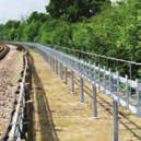
2 Anchor Posts Anchor Posts are an innovative patented* system designed by our founder, Ewan Smith, for lightweight foundations using hand held equipment. Ingeniously simple, they fulfil a widespread need for a fast and efficient way of securing small to medium foundations, without the need for concrete, in a variety of market sectors. Both versatile and adaptable, Anchor Posts provide a rapid and extremely cost-effective means of foundation installation that is up to ten times quicker than traditional methods. Furthermore, installing anchor posts requires minimal labour and equipment and all operations are completed during just one site visit. This combination of factors means that Anchor Posts offer major cost savings. *Patent Nos: Europe USA 12/372,965 2 ANCHOR SYSTEMS ANCHOR POSTS


3 Comprehensive Service With considerable experience of all aspects of ground and structural stabilisation, Anchor Systems offers comprehensive customer support including a design and specification service. Its personnel can give advice on the most suitable anchor post for individual projects with their specific load requirements, will conduct site tests and, if necessary, provide installation training or arrange installation via a recommended contractor. In addition, Anchor Systems also offers a wide range of other geotechnical and structural stabilisation systems which include Vulcan earth anchors, soil nails, helical anchors, anchor bolts, sock anchors and tree kits. ANCHOR POSTS ANCHOR SYSTEMS 3

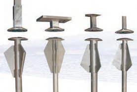
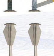
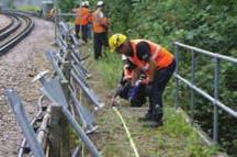
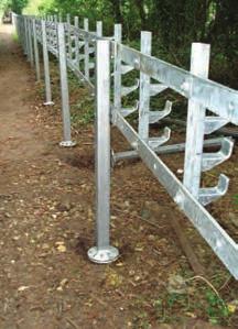
4 The System Anchor Posts come in a variety of sizes and formats for use in different applications but they all work on the same simple principle. Call us to discuss your particular requirements and we will advise on the most appropriate anchor post. Whatever your anchor post needs we can meet your demands or produce specials on request. Apart from its flexible usage, the principle benefit of the anchor post system is its speed of installation into most displaceable ground conditions. Once a C.A.T. scan has been conducted to detect any hidden utilities, the anchor is simply hammer driven straight into the ground. The alignment plate is then secured to the top at surface level and an interface plate of the required specification is bolted to the plate. It is immediately ready for its desired application fitting of signs, securing cable posts, fencing and the like. This rapid economical procedure allows far more posts to be positioned in considerably less time. Unlike traditional post installation methods, anchor posts require no digging, no concrete or curing time and no return visits, making them significantly quicker and more cost-effective. This is particularly important on rail and motorway installations, where any track or lane closures can be kept to a minimum and travel disruption can be avoided. 4 ANCHOR SYSTEMS ANCHOR POSTS

5 ANCHOR POSTS ANCHOR SYSTEMS 5
 as a rapidly installed post to support trackside cables on the LU Sub Surface Railway.")


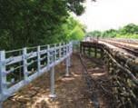
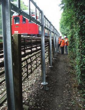
6 The Rail Industry The Anchor Post system was originally designed by Anchor Systems for Metronet Rail SSL (London underground) as a rapidly installed post to support trackside cables on the LU Sub Surface Railway. Since that time they have been used extensively in the rail industry, by both London Underground Ltd and Network Rail. Speed and ease of installation, by a small labour force, were all critical in Anchor Posts getting specified. Their versatility then resulted in them being used for a variety of other applications from cable stiles to foundations for lighting, signalling and embankment walkways. 6 ANCHOR SYSTEMS ANCHOR POSTS


7 ANCHOR POSTS ANCHOR SYSTEMS 7


 in a couple of hours rather than days and the")
8 Solar Panels With the growth in alternative sources of green energy, Anchor Posts have proven themselves to be an extremely reliable and efficient way to secure the support framework for solar farms. As many of these installations can be in relatively inaccessible rural locations, the fact that Anchor Posts need a limited amount of lightweight equipment and no concrete is a major practical benefit. Not only are Anchor Posts far quicker and cheaper to install but they are also seen as an environmentally friendly option as they are manufactured from recycled steel and they do not require concrete to be poured into the ground. Many companies wish to avoid such ground contamination, particularly if the land is to be returned to its natural state after its design life. What our customers say about the Anchor Post system The system meant we could install the required number of anchor points (16) in a couple of hours rather than days and the structural erection could begin as soon as the bolts were tightened. The equipment required was all fully portable, so easy to get on and off site and two men did all the installation once the marking out had been carefully completed. The system was remarkable in its simplicity but very, very effective. We are in the process of designing a new structure and will be using this system again. A leading solar panel installation contractor 8 ANCHOR SYSTEMS ANCHOR POSTS


9 Highways and other usages Anchor Posts have an extensive range of applications: Trackside cable management Cable stiles Lighting and signalling foundations Embankment walkway foundations Solar panels Road signs Gabions Motorway fencing Barriers Park and playground equipment Rockfall barriers Security fencing Mooring bollards Handrails Park benches Pipeline anchoring Cycle path signs Pedestrian signs Street furniture ANCHOR POSTS ANCHOR SYSTEMS 9


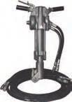

10 Equipment and Accessories Anchor Systems is able to supply a full range of necessary installation equipment and associated accessories. 10 ANCHOR SYSTEMS ANCHOR POSTS

11 Installation Testing Installing Anchor Posts is extremely quick and simple. 1. Mark out the position of each Anchor Post to be installed during the shift. 2. Make a 100mm deep x 300mm square dished excavation for each Anchor Post. 3. CAT scan the excavations to identify potential hazards, such as live cables or other services, to a depth of 2m. 4. Position the Anchor Post with the tip over the excavation, insert the drive rod and connect the hydraulic hammer and then lift the complete system to a vertical position. 5. Drive approx. 300mm then stop, ensure that the system is vertical and make any adjustment. Drive until the fins are 100mm from the bottom of the excavation then stop, check alignment again before final drive to depth. 6. Stop when the domed plate is at original ground level; do not drive the plate to the bottom of the excavation. 7. Fit a patch of Denso Tape over the top of the anchor post, covering the drive hole then position the cable post onto the Anchor Post and align vertically. 8. Fit the nuts and washers and hand tighten only. 9. Make final checks to ensure the post is vertical and then tighten the nuts gradually in rotation. 10. Only when all three nuts and bolts are tight, apply a 40Nm torque load using a certificated torque wrench. Do not over tighten. 11. The system is now complete and the lateral support rails can be connected to the cable posts and testing the system can proceed. Testing of the anchor post is a requirement, to prove the suitability of the ground conditions. Testing requirements are covered in a separate document, available form Anchor Systems, set out by the Design Engineers, Mitchell-Horton, and will be based on the site specific loading requirements. 1. Using a sledgehammer and a hand drive rod, percussion drive the AS-05 anchor into the ground, at the same angle as the pull direction (Normally 45 ), until just the loop at the end of the wire is showing above ground. 2. Place the drive rod through the loop in the wire and pull sharply. This will load-lock the anchor in the ground. 3. Connect the in-line load cell to the wire tendon using a D link shackle. Attach the chain pulley to the in-line load cell and the top of the cable post. 4. The Datum marker is then set at the base, directly in line with the load cell and on the opposite side, hard up against the dome plates. YOU ARE MEASURING THE MOVEMENT OF THE BASE PLATES, NOT THE DEFLECTION OF THE CABLE POST. 5. Using the chain pulley, load the system until the load cell reads the required test load for the length of cable post. 6. Measure and record any movement between the Datum and the plates. Record any recovery once the load on the cable post has been released. Full installation details are available on request from Anchor Systems. ANCHOR POSTS ANCHOR SYSTEMS 11
 Ltd")


12 Anchor Systems (International) Ltd Unit 45, Rowfant Business Centre, Wallage Lane, Rowfant, West Sussex, England RH10 4NQ Tel: +44 (0) Fax: +44 (0)
 INTRODUCTION TO HULK EARTH ANCHORS Anchoring Rope and Rigging PTY LTD are market leaders in the conceptualisation and production of innovative earth anchoring solutions used in a variety of engineered
The New Anchor Post Product
 The New Anchor Post Product From Anchor Systems This revolutionary foundation system is new to the Garden Room market. Benefit by using a foundation solution that is quicker, more efficient, less costly
Vulcan Tree Kits.
 Vulcan s Home of the Vulcan Earth Anchor ABOUT ANCHOR SYSTEMS (INTERNATIONAL) LTD INTRODUCTION TO VULCAN TREE KITS Anchor Systems (International) Ltd supplies ground anchors, helical anchors and concrete
Side-of-Pole Mount for 1 Module (SPM1) For Module Types A & B
 For Module Types A & B") Side-of-Pole Mount for 1 Module (SPM1) For Module Types A & B ASSEMBLY INSTRUCTIONS step-by-step assembly and installation Version 1, Rev A PCN 080311-2 SP3363-1 Side-of-Pole Mount for 1 Module (SPM1)
Side-of-Pole Mount for 1 Module (SPM1) For Module Types A & B ASSEMBLY INSTRUCTIONS step-by-step assembly and installation Version 1, Rev A PCN 080311-2 SP3363-1 Side-of-Pole Mount for 1 Module (SPM1)
BENEFITS OF TIGHTER ANCHORING SYSTEMS
 BENEFITS OF TIGHTER ANCHORING SYSTEMS The Tighter anchoring systems are very competitive on an initial analysis of prices. However, there are aspects of the system itself that makes it even more cost-effective.
Civil Application Solutions
 Civil Application Solutions Features - Chiseled Cutting Edges - Increased Surface Area - Lateral Direction Guide Ribs Benefits - Faster Installation and Penetrates Harder Soils - Quicker Loading, Stronger
Tripod Setup Guide (M-TPx)
") Items needed: 1/2 inch wrench, mast level (M-MLA), medium size wire cutters, crescent wrench, all-purpose grease, tape measure, tie wraps, redi-mix cement (optional), shovel (optional), sledge hammer (for
Items needed: 1/2 inch wrench, mast level (M-MLA), medium size wire cutters, crescent wrench, all-purpose grease, tape measure, tie wraps, redi-mix cement (optional), shovel (optional), sledge hammer (for
Tips on Permanent Powered Fencing and Temporary Powered Fencing
 Tips on Permanent Powered Fencing and Temporary Powered Fencing The following outlines various simple, yet proven, methods in constructing both fixed and portable fencing systems as well as providing information
Precision Liquid Settlement Array Manual
 Precision Liquid Settlement Array Manual All efforts have been made to ensure the accuracy and completeness of the information contained in this document. RST Instruments Ltd reserves the right to change
Soma Wind Generators
 Soma Wind Generators 13M WINH TOWER INSTALLATION MANUAL ERTIFIED to AS4100 Steel Structures ode AS3995 (1994) Design of Steel Lattice Towers and Masts AS1170.2 (1989) SAA Wind Loading Manufactured by SOMA
1) INTRODUCTION 2) THE UNFAIR ADVANTAGE
 INTRODUCTION 2) THE UNFAIR ADVANTAGE") 1 1) INTRODUCTION 2) THE UNFAIR ADVANTAGE and Stingray earth anchors are driven tipping plate soil anchors for reaction of tensile loads. anchors have ultimate capacities up to 20 tons, and Stingray anchors
1 1) INTRODUCTION 2) THE UNFAIR ADVANTAGE and Stingray earth anchors are driven tipping plate soil anchors for reaction of tensile loads. anchors have ultimate capacities up to 20 tons, and Stingray anchors
TOWER INSTALLATION MANUAL For A.R.E. Guyed Pipe Towers Short Towers 43, 64 and 85 feet tall
 TOWER INSTALLATION MANUAL For A.R.E. Guyed Pipe Towers Short Towers 43, 64 and 85 feet tall Contents 1) Introduction...2 2) Site Selection and Preparation...2 3) Tools List...3 4) Parts List...4 5) Tower
Utility Anchor System
 Utility Anchor System The Dayton Superior Utility Anchor System is designed to economically simplify the lifting and handling of precast concrete elements. Its economics, ease of use and versatility will
P R I M A X. The Most Advanced Shoring Devices SAFER - FASTER - DEEPER - CHEAPER THE ULTIMATE SHORING TECHNIQUES ARE NOW ON YOUR HANDS
 P R I M A X The Most Advanced Shoring Devices SAFER - FASTER - DEEPER - CHEAPER SLIDE RAIL SHORING ENGINEERING SLIDING STRUT SHORING TRENCH SHIELD SELF PROPELLED SHIELD CONSULTING SHORING DESIGN MANHOLE
CHAINLESS ANCHORING SYSTEM USER MANUAL
 CHAINLESS ANCHORING SYSTEM USER MANUAL Introduction..................................................... 1 Setting up the Chainless Anchoring System............................ 4 Set up Procedure............................................
NEXT GENERATION FLEX FENCE
 NEXT GENERATION FLEX FENCE Area To Be Fenced.. With Next Generation Flex Fence any post that is not in a straight line with another post must be braced. Layout your fence installation. Determine all end
Low Wind High Yields Series
 Low Wind High Yields Series Wind Turbines USER S MANUAL Introduction Low Wind High Yields Series rotor blades apply the latest advanced thermoplastic engineering and are manufactured by precision injection
Fiber Cable Puller with Tuf-Lugger lite
 7 OPERATING INSTRUCTION MANUAL Fiber Cable Puller with Tuf-Lugger lite Copyright 2015 DCD Design & Manufacturing Ltd. Revision 1.0 IMPORTANT SAFETY INSTRUCTIONS READ ALL INSTRUCTIONS BEFORE USING The Fiber
Model: 7200 Collegiate Volleyball System
 Model: 7200 Collegiate Volleyball System Installation, Operation and Maintenance Instructions Please read all instructions before attempting installation or operation of these units SAVE THESE INSTRUCTIONS
Side-of-Pole Mount for 1 Module (SPM1) For Module Type C
 For Module Type C") Module Type Width Length C 22-27 56-63 Side-of-Pole Mount for 1 Module (SPM1) For Module Type C ASSEMBLY INSTRUCTIONS step-by-step assembly and installation Version 1, Rev A PCN 022212-1 Side-of-Pole Mount
Module Type Width Length C 22-27 56-63 Side-of-Pole Mount for 1 Module (SPM1) For Module Type C ASSEMBLY INSTRUCTIONS step-by-step assembly and installation Version 1, Rev A PCN 022212-1 Side-of-Pole Mount
Side-of-Pole Mount for 1 Modules (SPM1) For Module Types E, F, G, & H ASSEMBLY INSTRUCTIONS. step-by-step assembly and installation
 For Module Types E, F, G, & H ASSEMBLY INSTRUCTIONS. step-by-step assembly and installation") Side-of-Pole Mount for 1 Modules (SPM1) For Module Types E, F, G, & H ASSEMBLY INSTRUCTIONS step-by-step assembly and installation Version 1, Rev A SP3348-1 PCN 022212-2 Side-of-Pole Mount for 1 Module
Side-of-Pole Mount for 1 Modules (SPM1) For Module Types E, F, G, & H ASSEMBLY INSTRUCTIONS step-by-step assembly and installation Version 1, Rev A SP3348-1 PCN 022212-2 Side-of-Pole Mount for 1 Module
THOR 10 HAMMER CAGE INSTRUCTIONS
 75 " 7m 78 4" m 6" 8.8m 45 ".70m 4.9deg 6 4" 6m 44 4".67m 75 " 7m 9 4" 0m 44".m 497 4".64m The 70, Thor Hammer Cage, consists of four heavy duty aluminum net poles. The unique pole structure reduces the
Installation and Training Manual
 AirForce1 Tower Kit Installation and Training Manual FuturEnergy Limited Ettington Park Business Centre Stratford upon Avon CV37 8BT +44 (0)1789 451070 Table of Contents Safety Notes... 3 Parts Supplied
Field Instruction. Protect Horizon Power employees and contractors from a potential hazard.
 2.15 Temporary Safety Barriers and/or Warning Signs Purpose This instruction sets out the minimum requirements for the installation and erection of temporary safety barriers and/or warning signs to: Protect
Cat Fence Installation Instructions for Regular and Snow Protection Kits with Extra Posts. List of items shown
 CF-INST-E, Rev., 0/7/ Cat Fence Installation Instructions for Regular and Protection s with Extra Posts Attachment Close-up Regular Regular Post with Post Attached A B F K J E C D I G, H L List of items
DDS TECHNOLOGY MARKER SYSTEMS
 DDS TECHNOLOGY MARKER SYSTEMS G.A. Valves Sales Limited - P.O.Box 5, Brighouse, West Yorkshire HD6 3UD Tel:- 01484711983 Fax:- 01484719848 email :- sales@gavalves.co.uk DRIVE IN MARKER POSTS High density
Safety System Installation Guide for ARE Wind Poles
 Safety System Installation Guide for ARE Wind Poles V. 1 May 2011 ** Climbing pegs and ladder should be installed before the pole is erected.** A. Install climbing pegs Install climbing pegs (bolt set)
Blocks must always run perpendicular (at 90 degrees) to the fence to ensure adequate stability.
 to the fence to ensure adequate stability.") This information paper is to provide minimum guidelines and information of the erection of temporary fencing for the purpose of barricading, delineation of a work area, and for protection of workers from
This information paper is to provide minimum guidelines and information of the erection of temporary fencing for the purpose of barricading, delineation of a work area, and for protection of workers from
Troyer s Gourd Rack 8 unit F R H O P
 B E A D I M-N L Vertical Parts F R H O P Horizontal Parts C G J Updated 11/16 Parts List A: Top of Pole B: Bottom of Pole C: 48 Ground Stake D: Top Perch rods 48 long E: Hub F: Rope Winder w/ attached
SPOOLER INSTRUCTIONS. STEP 12 If you are going to paint your posts, that should be done at this time.
 STEP 4 Starting where you marked the end post location, move down your fence line 6 feet and make another mark. This mark is where your second upright post will be installed. Continuing down the fence
The cost-efficient fixing for flexible use in non-cracked concrete VERSIONS. zinc-plated steel stainless steel hot-dip galvanised steel
 The cost-efficient fixing for flexible use in non-cracked concrete VERSIONS APPROVALS zinc-plated steel stainless steel hot-dip galvanised steel BUILDING MATERIALS Approved for: Concrete C20/25 to C50/60,
CAISSON SHAFT SYSTEM
 CAISSON SHAFT SYSTEM Installation Guide INSTALLATION GUIDE FOR DN2000 TO DN3660 UNITS PLATE JOINTING SYSTEM This guide is to be used for the Installation of CPM Group Ltd caisson shaft units which use
Certified Accuracy. Ring Force Gauge. Models and Capacities Available. Design and Principle of Operation
 Certified Accuracy Ring Force Gauge The accurate measurement of mechanical forces is required in hundreds of applications from a simple weighing procedure to the calibration of testing machines and load
Anchors that can be used for a lifeline in a grain bin. or Ladder do not make good anchors!
 Anchors that can be used for a lifeline in a grain bin. or Ladder do not make good anchors! Definitions: Carabiner 1 Webbing attachment hardware with double locking action rated at 4,000 pounds 8 mm Accessory
PRO1030 Bi-Directional Assembly Replacement
 PRO1030 Bi-Directional Assembly Replacement 1. Remove both side covers using the Crank and Cover Removal procedure. Fig. 1 2. Disconnect both brake cables (not shown) from the brake (S3611). (Fig. 1) 3.
PLACEMENT OF SIGNS RECOMMENDED PRACTICES SUB-SECTION
 Page 1 of 6 RECOMMENDED PRACTICES PART SECTION SUB-SECTION HIGHWAY SIGNS GENERAL General Proper positioning of signs is an important element in the overall control of traffic within a roadway network.
Array Solutions 350 Gloria Rd Sunnyvale, TX Phone FAX
 Array Solutions 350 Gloria Rd Sunnyvale, TX 75182 Phone 972-203 2008 FAX 972-203 8811 E-mail: info@arraysolutions.com Installation Instructions AS-AYL-4 WM Array Solutions K9AY Loop Wire/Mast Kit Thank
How to install AEA s 10 meter meteorological tower
 How to install AEA s 10 meter meteorological tower Before you start: This guide assumes that you have obtained permission from the land owner, consulted with US Fish & Wildlife Service and obtained approval
RATCHET RELEASE SHACKLE
 RATCHET RELEASE SHACKLE INNOVATIVE PILING EQUIPMENT HYDRAULIC PILING HAMMERS EURO RATCHET RELEASE SHACKLE FOR STEEL ERECTION OPERATORS INSTRUCTIONS & SPARE PARTS LIST EXCAVATOR MOUNTED VIBRATORS EXCAVATOR
Allspeeds Ltd. Royal Works, Atlas St Clayton le Moors Accrington Lancashire England BB5 5LW. Tel +44 (0)
") Allspeeds Ltd. Royal Works, Atlas St Clayton le Moors Accrington Lancashire England BB5 5LW Tel +44 (0)1254 615100 www.allspeeds.co.uk WIRE ROPE GRIPPER WGO135 (without manifold and intensifier) PRODUCT
Allspeeds Ltd. Royal Works, Atlas St Clayton le Moors Accrington Lancashire England BB5 5LW Tel +44 (0)1254 615100 www.allspeeds.co.uk WIRE ROPE GRIPPER WGO135 (without manifold and intensifier) PRODUCT
Allspeeds Ltd. Royal Works, Atlas St Clayton le Moors Accrington Lancashire England BB5 5LW. Tel +44 (0)
") Allspeeds Ltd. Royal Works, Atlas St Clayton le Moors Accrington Lancashire England BB5 5LW Tel +44 (0)1254 615100 www.allspeeds.co.uk SOFTLINE CUTTER SL80 PRODUCT CODE No. 980248 INSTRUCTIONS FOR INSTALLATION,
Allspeeds Ltd. Royal Works, Atlas St Clayton le Moors Accrington Lancashire England BB5 5LW Tel +44 (0)1254 615100 www.allspeeds.co.uk SOFTLINE CUTTER SL80 PRODUCT CODE No. 980248 INSTRUCTIONS FOR INSTALLATION,
No ' Long No ' Long
 ASSEMBLY, INSTALLATION & USAGE MANUAL BATTING CAGES No. 0150-50' Long No. 0170-70' Long No. 0150 BATTING CAGE - 50' Long No. 0170 BATTING CAGE - 70' Long Upon completion of the assembly/installation of
Tree Anchoring. Greening the Built Environment VERTICAL GARDENS. GREEN FACADES. ROOF GARDENS
 Tree Anchoring Greening the Built Environment VERTICAL GARDENS. GREEN FACADES. ROOF GARDENS Why choose our Tree Anchor System? We are proud to bring you an Australian made tree anchoring system. Our new
WIRE ROPE PULLING MACHINE
 WIRE ROPE PULLING MACHINE Spare parts list and exploded view Specifications Dimensions Item No. 0.8T 1.6T 3.2T 5.4T Rated Capacity kg 800 1600 3200 Rated Forward Handpower N 343 441 441 Rated Forward Travel
VSL MINING & TUNNELING SYSTEMS VSL. mining and tunneling
 VSL MINING & TUNNELING SYSTEMS VSL mining and tunneling VSL Mining & Tunneling Bolt systems VSL offers three type of bolting system for the mining & Tunnelling industry VSL-S Solid Threaded bolts. Continuous
STATIONARY TRUCK INTERNAL HALYARD V-CLEAT FLAGPOLES FOR QUICK AND PROFESSIONAL INSTALLATION READ ALL INSTRUCTIONS BEFORE PROCEEDING
 9390 South 300 West, Sandy, Utah 84070 801-562-0123 800-782-0500 ColonialFlag.com STATIONARY TRUCK INTERNAL HALYARD V-CLEAT FLAGPOLES FOR QUICK AND PROFESSIONAL INSTALLATION READ ALL INSTRUCTIONS BEFORE
Allspeeds Ltd. Royal Works, Atlas St Clayton le Moors Accrington Lancashire England BB5 5LW. Tel +44 (0)
") Allspeeds Ltd. Royal Works, Atlas St Clayton le Moors Accrington Lancashire England BB5 5LW Tel +44 (0)1254 615100 www.allspeeds.co.uk SOFT LINE CUTTER SL55 PRODUCT CODE No. 980504 INSTRUCTIONS FOR INSTALLATION,
Allspeeds Ltd. Royal Works, Atlas St Clayton le Moors Accrington Lancashire England BB5 5LW Tel +44 (0)1254 615100 www.allspeeds.co.uk SOFT LINE CUTTER SL55 PRODUCT CODE No. 980504 INSTRUCTIONS FOR INSTALLATION,
Row Marker OEM /
 IMPORTANT: Your new row marker is designed to attach to the Troy-Bilt Hiller-Furrower attachment. If you don t have Hiller- Furrower, call us or visit www.troybilt.com to place an order: OEM-290-250 for
Work Standard CABLE PULLING OPERATIONS
 Page 1 of 19 ****This document supercedes BECo WMS 2.9-1.1**** 1.0 Purpose CABLE PULLING OPERATIONS 1.1 This Work Method Standard prescribes the preferred methods of removing and installing cables between
Assembly Instructions. -Cantilever Boat Lifts
 Assembly Instructions -Cantilever Boat Lifts Winch Instruction Page Safety Information 1. The winch is built for the multipurpose of hauling and lifting operations. It is not to be used as a hoist for
IS37 10 Metre Instrument Mast Handbook
 IS37 10 Metre Instrument Mast Handbook Version 10.1 6 th February 2014 Environdata Australia Pty Ltd 42-44 Percy Street Warwick Queensland 4370 Australia Phone: (07) 4661 4699 Fax: (07) 4661 2485 International
2012 K9100 COMPACT Worldwide Cycling Solutions Through Creative Innovations.
 Home Instruction Sheet Step-1Please check for any missing parts. Model K9100 COMPACT (Basic AirCaddy) aircaddy web page 20 04/03/12 98% (1) T3230-00 METAL WHEEL TRUCK Model K8350 (Aircraft Kit) (Optional)
Versie Date: USAGE AND SAFETY MANUAL SPREADERBEAMS
 USAGE AND SAFETY MANUAL SPREADERBEAMS 1. INTRODUCTION: The spreader system exists of modular traverses with possibility of different spans. Each spreaderbeam exists of two head section complete with shackles
FITNESS, SAFETY & MEDICAL SUPPLIES
 COMMERCIAL SERIES LIFTS TABLE OF CONTENTS 1. TRI-Point Anchor System 2. TRI-Point Paver Instruction Anchor Method 3. TRI-Point Retro-Fit Anchor System 4. TRI-Point Drop In Anchor System 5. Commercial Series
MAKE BOLLARD IMPACT RESISTANT PROTECT FOUNDATIONS RE-USE BOLLARD
 \\ PROTECT FOUNDATIONS In-ground or surface mount Impact Recovery System protects foundations from damage when bollards are impacted, need replacing or upgrading. Surface mount version uses Impact resistant
Translation of the original Operating Instructions for HKS rubber compensators
 Because of their flexible elements and mechanisms, HKS rubber compensators are susceptible to damage of all types and adverse loads in operation. For reliable operation of a compensator and, thus, the
Model: 5100 OmniSteel Volleyball System
 Model: 5100 OmniSteel Volleyball System Installation, Operation and Maintenance Instructions Please read all instructions before attempting installation or operation of these units SAVE THESE INSTRUCTIONS
QUALITY ALUMINUM BOAT LIFTS, INC. INSTRUCTIONS. Dominator Lake Lift
 INSTRUCTIONS Dominator Lake Lift PHONE:251-986-3882 * FAX:251-986-3136 QABLDOMINATORINST.2014 P a g e 1 Quality Aluminum Boat Lifts, INC. Installation Instructions: Dominator Lake Lift Thank you for your
Swing Set. Sheffield Model 22-PS320
 Swing Set Sheffield Model 22-PS320 Important! The owner s manual contains safety, assembly, use and maintenance instructions. The Playsafe Swing Set must be assembled by an adult who has read and understands
BUOYA Y NCY CONTROL FOR PIPELINES
 BUOYANCY CONTROL FOR PIPELINES INTRODUCTION Platipus Anchors are market leaders in the design, manufacture and supply of mechanical earth anchoring products. The company is renowned for providing some
DG Prospector TM Owner s Manual and Installation Guide 3-CMLT-1414 Rev B
 DG Prospector TM Owner s Manual and Installation Guide 3-CMLT-1414 Rev B Assembly Installation Maintenance 2014 XZERES Corp All Rights Reserved XZERES Wind Congratulations on your purchase and welcome
BUTTERFLY VALVES Series 800
 BUTTERFLY VALVES Series 800 WARNING Before proceeding read ALL instructions and become familiar with the equipment and associated drawings. Follow ALL applicable safety regulations and codes for pressurized
Instant Garage 20' x 12' 3" x 8' 3"
 Instant Garage 20' x 12' 3" x 8' 3" Assembly Instructions Description Model # Instant Garage 20' x 12' 3" x 8' 3" - Grey CIG 1220 3503502 Recommended Tools OR THIS IS A TEMPORARY STRUCTURE AND NOT RECOMMENDED
Shade Sails - Installation Tips
 Shade Sails - Installation Tips Shade Sails Installation Suggestions Design and Layout: Shade Sails can be mounted in a variety of ways. Sails can be mounted flat or with high and low points. A flat sail
MIRABAY PILOT PROJECT REPORT
 MIRABAY PILOT PROJECT REPORT 9/25/2014 By: Ingenium, Inc./Carl A. Hazenberg, P.E. Seawalls along the MiraBay canal system started experiencing problems shortly after construction. Following the issues,
FLEXIBLE AND RELIABLE ANCHORING
 Spiral rope anchor and FLEX Head FLEXIBLE AND RELIABLE ANCHORING 1 THE SMARTER ANCHOR FLEXES. The flexibility of the whole system is crucial for both rockfall barriers and other protection systems. Why?
POP UP ANCHOR. Part Number Spectrum Lane ~ Missoula MT ~
 POP UP ANCHOR Part Number 153169 7100 Spectrum Lane ~ Missoula MT 59808 800.791.8056 ~ www.spectrumproducts.com You have purchased a Spectrum Products Pop Up Lane Rope Anchor. Providing the unit is installed
USER MANUAL. Beach volleyball posts BEACH CHAMP ID:
 USER MANUAL Beach volleyball posts BEACH CHAMP ID: 111203 INDEX USER MANUAL FOR BEACH VOLLEYBALL POSTS BEACH CHAMP General information Overview Overview: Floor mounting options City Beach - for a freestanding
INSTALLATION COMMISSIONING, OPERATION & MAINTENANCE MANUAL
 WedgeRock RW Series Worm Gear Actuators INSTALLATION COMMISSIONING, OPERATION & MAINTENANCE MANUAL Revision 01 Date 4/3/17 Page 1 Table of Contents 1.0 INTRODUCTION... 4 1.1 PURPOSE... 4 1.2 AUDIENCE...
GATES, CATTLE GUARDS AND PASSAGEWAYS. This factsheet looks at various options for allowing passage through fences for livestock, wildlife and people.
 Fencing Order No. 307.400-1 Revised December 2015 GATES, CATTLE GUARDS AND PASSAGEWAYS This factsheet looks at various options for allowing passage through fences for livestock, wildlife and people. GENERAL
Important Note: Tighten lock nuts so the support tubes still swing freely see figure 2. There must be 1 2 threads of bolt past end of lock nuts.
 Kit Contents: DESCRIPTION QTY. DESCRIPTION QTY. 2 Shank Assembly 1 Support Tube Assembly 1 Side Tube - Short 2 1-1/4 Shank 1 Center Tube - Long 1 3/8-16 x 2.0 Carriage Bolt 2 5/16-18 x 2.25 Carriage Bolt
CLIENT NAME: LOCATION: CALM BUOY INSPECTION:
 INSPECTOR REVIEWED INSPECTION OF CALM BUOY OVERALL PHOTO REVISION DESCRIPTION: Preliminary / Final Page: 1 TABLE OF CONTENT 1. MANAGEMENT SUMMARY... 3 1.1. SCOPE OF WORK:... 3 1.2. CORRECTIVE ACTIONS...
Anchor Load Cells. Among the different types that are used as anchor load cells
 Chapter: 3.1 Anchor Load Cells Page No.: 1 Number of Pages: 1 In rock and base engineering anchors are applied as construction element. They stabilise the rock by absorbing axial load and shear forces.
WEIGHT STACK ATTACHMENT. Assembly Manual (888) FOR YOUR SAFETY READ ALL INSTRUCTIONS CAREFULLY
 FOR YOUR SAFETY READ ALL INSTRUCTIONS CAREFULLY") WEIGHT STACK ATTACHMENT Assembly Manual DF835 (888) 258-0533 FOR YOUR SAFETY READ ALL INSTRUCTIONS CAREFULLY *NOTE IF YOU ARE MISSING HARDWARE OR HAVE ANY FIT UP PROBLEMS PLEASE CONTACT DELTECH FITNESS
WEIGHT STACK ATTACHMENT Assembly Manual DF835 (888) 258-0533 FOR YOUR SAFETY READ ALL INSTRUCTIONS CAREFULLY *NOTE IF YOU ARE MISSING HARDWARE OR HAVE ANY FIT UP PROBLEMS PLEASE CONTACT DELTECH FITNESS
Instant Garage 16' x 12' 3" x 8' 6"
 Instant Garage 16' x 12' 3" x 8' 6" Assembly Instructions Door Height 1.8M A B DESRIPTION MODEL # A B IG 1216 Instant Garage 4.9 x 3.7 x 2.6 M - Grey 3503500 16' x 12' 3" x 8' 6" REOMMENDED TOOLS OR Please
Heavy Equipment & Rigging Specialist Training
 Heavy Equipment & Rigging Specialist Training Module 1 Unit 4: Intro to Rigging May08 1 Key Points Review of Exercise Goals Discuss Rigging Components Language of Crane Signals Review Anchor Installation
Recommendations for Marking Communication Facilities
 Recommendations for Marking Communication Facilities with the Use of 3M EMS Electronic Markers Revised June 21, 2005 Page 1of 12 1.0 Overview The 3М TM electronic marker system is intended to make the
MSA Confined Space Entry Equipment
 MSA Confined Space Entry Equipment Because every life has a purpose... MSA Confined Space Entry Equipment MSA XTIRPA Manhole Guard System Use for confined space vertical entry and fall protection when
BALL STOP INSTALLTION GUIDE
 BALL STOP INSTALLTION GUIDE GROUND SLEEVE INSTALLATION: 1. Locate the exact location of the ground sleeve. NOTE: Maximum recommended pole spacing is 20 feet on center. 2. Excavate the pole footing; refer
STATIONARY TRUCK INTERNAL HALYARD CAM CLEAT FLAGPOLES FOR QUICK AND PROFESSIONAL COMMERCIAL INSTALLATION READ ALL INSTRUCTIONS BEFORE PROCEEDING
 9390 South 300 West, Sandy, Utah 84070 801-562-0123 800-782-0500 ColonialFlag.com STATIONARY TRUCK INTERNAL HALYARD CAM CLEAT FLAGPOLES FOR QUICK AND PROFESSIONAL COMMERCIAL INSTALLATION READ ALL INSTRUCTIONS
Cable Replacement Instructions for R-Series Roust-A-Bout 100/150/250
 Cable Replacement Instructions for R-Series Roust-A-Bout 100/150/250 US 7514 Alabonson Road Houston, TX 77088 phone: 281-999-6900 fax: 281-999-6966 Canada 1721 Bishop St. Unit #4 Cambridge, ON N1T 1N5
American Flagpole & Flag Co. 1(800)
") SENTRY CONCEALED HALYARD-REVOLVING TRUCK GROUND SET INSTALLATIONS INSTRUCTIONS 1. Dig foundation as detailed in SECTION A FOUNDATION SPECIFICATIONS, set sleeve in enter of hole with top 2 above grade.
SENTRY CONCEALED HALYARD-REVOLVING TRUCK GROUND SET INSTALLATIONS INSTRUCTIONS 1. Dig foundation as detailed in SECTION A FOUNDATION SPECIFICATIONS, set sleeve in enter of hole with top 2 above grade.
Ground Release Shackle
 Operator Manual Subhead Advantages: In the process of installing Slide Rail, the shackle connecting the top of posts, panels, and sheeting must be removed manually. This is normally done by climbing on
TRAVSMART permanent single-cable horizontal lifeline system
 The Travsmart single-line system provides a smooth travel. It allows the traveler to move freely over the intermediate anchors, minimizing wear and eliminating user assistance. The user s hands remain
Wellhead Mast. Installation and Operation Guide. Nanometrics Inc. Kanata, Ontario Canada
 Installation and Operation Guide Nanometrics Inc. Kanata, Ontario Canada 2001 2005 Nanometrics Inc. All Rights Reserved. Installation and Operation Guide The information in this document has been carefully
Fencing. Fencing - a look back in time
 Fencing Fencing - a look back in time In olden days, when grazing animals grazed outlying land, fields and meadows were fenced in to protect crops from domestic livestock. Nowadays, animals no longer as
INSTALLATION INSTRUCTIONS: SCTB1600
 INSTALLATION INSTRUCTIONS: SCTB1600 DESCRIPTION: BOLLARD, 1600 DWG: INSTALL_SCTB1600 REV: M01 BASE TYPE B1 DIRECT BURIAL - PG. 6: BOLLARD IS PERMANENT, IT IS DIRECTLY BURIED INTO CONCRETE BASE TYPE B2
Page 1 of 1 04/19/13 SBR
 Office of Roadway Engineering - Plan Insert Sheets Number Title Date Number Title Date Number Title Date 201015 Extension of Anchor Bolts 07/20/12 207000 Bikeway Pavement Marking Details 01/18/13 202010
Foundation Products. Poured In Ground Anchor Bolts E1 - E4. Structural Foundations E5 - E12. Copyright 2016 s Industry Inc. SIE-RA-CMP EN
 Foundation Products Poured In Ground Anchor Bolts E1 - E4 Structural Foundations E5 - E12 EA EB Poured in Ground Anchor Bolts Layout SIEMENS Anchor Bolts 131702-4X shown for reference purposes only! Actual
SERIES 2 RAMP OWNER S MANUAL TOOLS REQUIRED: BEFORE YOU BEGIN... Read and understand these instructions before beginning a ramp setup.
 SERIES 2 RAMP OWNER S MANUAL BEFORE YOU BEGIN... Read and understand these instructions before beginning a ramp setup. Use caution and care for your back when lifting, pushing, pulling, folding or unfolding
Single slide rail system Linear shoring
 E+S Trench shoring systems / Sliding rail systems Single slide rail system Linear shoring Single-rail linear shoring with U-type and rectangular roller unit Module length Length slide rail Panel height
Product Catalog and Pricing
 2015 Prices effective December 1, 201 www.greenebinstairs.com Product Catalog and Pricing 177 Main Street; PO Box 191 All Galvanized Material East Lynn IL 60932 F.O.B. East Lynn IL 60932 217-375-2; FAX
Paddle Bar Replacement
 This procedure is to help facilitate the replacement of the 23 Paddle Bar Assembly on the ANKOM Dietary Fiber Analyzer. Note: The following items will be sent in a replacement package as part of the 23
WHERE THERE S A WINCH, THERE S A WAY!
 WHERE THERE S WINCH, THERE S WY! TM RING POWER WHERE YOU NEED IT! TM Portable Winch Co. is the world s leading manufacturer of portable gas-powered (petrol-powered) winches. Unlike other winches, ours
Installing a Christie One Mount/Christie One Mount Plus
 Installing a Christie One Mount/Christie One Mount Plus This document provides instructions for installing the Christie One Mount or Christie One Mount Plus and optional accessories to mount Christie projectors
Containment Solutions
 0013_01_UK 2010 Combisafe International Ltd. Reservation for technical changes. Containment Solutions New Systems Combisafe International Ltd Safety Centre, Cheaney Drive, Grange Park, Northampton NN4
Installation, operation & maintenance manual - original version
 Installation, operation & maintenance manual - original version AVK gate valves for water and wastewater Series 01, 02, 06, 12, 15, 18, 20, 26, 32, 33, 36, 38, 50, 55 and 636 COPYRIGHT AVK GROUP A/S 2018
S-60-TO : 1 ton tower system INSTRUCTION MANUAL
 S-60-TO : 1 ton tower system INSTRUCTION MANUAL LIVE SYSTEMS bvba Mandellaan 282 8800 B-Roeselare Tel: +32(0)51 69 38 14 Mobile : +32 (0) 495 24 24 67 e-mail: ricky@livesystems.be BTW : 0859.636.665 1
EUSMUNC06 (SQA Unit Code - FG2W 04) Locate and avoid supply apparatus for Utilities Network Construction
 Locate and avoid supply apparatus for Utilities Network Construction") Locate and avoid supply apparatus for Utilities Network Construction Overview This national occupational standard defines the competence involved in locating and avoiding supply apparatus by using appropriate
Locate and avoid supply apparatus for Utilities Network Construction Overview This national occupational standard defines the competence involved in locating and avoiding supply apparatus by using appropriate
by Master Halco ANCHOR GATE SYSTEMS Swing Gates Overhead Slide Gates Cantilever Slide Gates Vertical Lift Gates Fencing Without Boundaries.
 by Master Halco ANCHOR GATE SYSTEMS Swing Gates Overhead Slide Gates Cantilever Slide Gates Vertical Lift Gates Fencing Without Boundaries. The Better Way To Build Your Cantilever Slide Gates... The Principle