An Evaluation of Bathymetric LiDAR Systems
|
|
|
- Hilary Hood
- 5 years ago
- Views:
Transcription

1 An Evaluation of Bathymetric LiDAR Systems September 2006
2 Table of Contents AN EVALUATION OF BATHYMETRIC...I LIDAR SYSTEMS...I SEPTEMBER I 1. INTRODUCTION INTRODUCTION TO LIDAR TECHNOLOGY Overview Airborne LiDAR Bathymetric Mapping Airborne bathymetric LiDAR deliverables THE BENEFITS OF AIRBORNE LASER BATHYMETRY Speed of data collection cost effectiveness Repeatability Ability to survey a seamless transition zone Ability to survey shallow, rocky and hazardous areas Acquisition by night Habitat Mapping THE LIMITATIONS OF AIRBORNE LIDAR BATHYMETRY Water Clarity Object detection and Depth accuracy LIDAR DATA AND IHO STANDARDS Navigational Accuracy SYNOPSIS OF AVAILABLE SYSTEMS AVAILABLE SYSTEMS System 1 Airborne Hydrography AB Hawk Eye II System 2 & 3 Optechs SHOALS 1000T and 3000T WORLD APPLICATIONS OF BATHYMETRIC LIDAR MAPPING MARKET ANALYSIS Manufacturing Market Services Market REFERENCES Table of Figures FIGURE 1 AIRBORNE LIDAR BATHYMETRIC SYSTEM... 3 FIGURE 2 SHALLOW WATER LIDAR VS. MULTIBEAM... 5 FIGURE 3 3-D REFLECTANCE IMAGERY DATA FIGURE 4 REFLECTANCE AND HYPERSPECTRAL DATA COMBINED... 7 FIGURE 5 WATER CLARITY MEASUREMENTS WITH A SECCHI DISK... 8 FIGURE 6 OBJECT DETECTION MULTIBEAM VS LIDAR DATA... 9 FIGURE 7 DEPTH ACCURACY OF LIDAR VS SINGLEBEAM ECHOSOUNDER... 9 FIGURE 8 HAWK EYE SYSTEM PRINCIPLE FIGURE 9 SEAMLESS HAWK EYE SURVEY FIGURE 10 HAWK EYE TOP LEVEL SYSTEM ARCHITECTURE FIGURE 11 THE HAWK EYE SURVEY SYSTEM i
3 FIGURE 12 THE HAWK EYE SYSTEM INSTALLED IN AN AERO COMMANDER FIGURE 13 SHOALS SYSTEM SENSOR HEAD, CONTROL RACK AND LASER FIGURE 14 SHOALS 1000T INSTALLED IN A SMALL AIRCRAFT FIGURE 15 THE IMPORTANCE OF AN INTEGRATED DIGITAL CAMERA ii
4 1. Introduction The purpose of this report is to evaluate the available bathymetric LiDAR (Light Detection and Ranging) systems on the market with the intention of purchasing a system for the Irish Government. The Irish National Seabed Survey (INSS) charted more than 468,500 km 2 of seabed; most of the areas surveyed were at the outer margins of Irelands territorial seabed. The successive program to INSS is INFOMAR: INtegrated Mapping For the sustainable development of Irelands MArine Resource, this is a twenty year survey program which began this year in The seabed mapping proposed by INFOMAR will include the mapping of our commercially valuable inshore areas, so perhaps the most crucial body of mapping now looms. A large area of this inshore mapping, up to 7000 km 2, could be effectively charted using LiDAR; a bathymetric light detection and ranging instrument that is mounted on a light aircraft thus enabling large areas to be surveyed in a time and cost effective manner. With the data acquired by the INSS and subsequently INFOMAR, the Marine Institute and Geological Survey of Ireland will bring Irelands charts into the 21 st century by improving the quality and accuracy of soundings and thus fulfill Irelands obligations under SOLAS. Ireland is a signatory to the International Convention SOLAS, for the Safety of Life at Sea. New amendments which came into force in July 2002 require Ireland to arrange for the collection and compilation of hydrographic data and the publication, dissemination and keeping up to date of all nautical information necessary for safe navigation. The availability of seabed data is essential for the accurate compilation of navigation charts and under SOLAS contracting governments are required to provide this hydrographic data. 2. Introduction to LiDAR Technology 2.1 Overview Red Eye topographic surveying A typical Airborne Light Detection and Ranging (LiDAR) system uses a scanning laser to measure the time it takes for a laser pulse to travel from the sensor to the ground and back to the sensor, thus measuring the distance from the sensor to the ground. The laser source projects a laser beam onto a spinning or scanning mirror sending a brief pulse of laser light to the earth s surface. The mirror is rotated or scanned at an extremely fast rate, enabling the LiDAR system to project thousands of laser pulses per second thus creating a dense swath of laser points on the ground. The reflected laser pulse is detected by the system, which then, based on the time of travel and aircraft position and attitude, computes the x, y and z position of each reflection point (i.e. the ground or other intermediate object). The LiDAR system is coupled with a Global Positioning System (GPS) to determine aircraft position and an Inertial Navigation System (INS) to determine the aircraft attitude and so produce geo referenced points on the ground. The distance measurement accuracy is typically 2-25cm depending on the sensor type and flight conditions, enabling users to have the benefit of highly accurate Digital Elevation Models (DEMs) that can be collected day or night and in a variety of weather conditions. This red eye or infrared laser technology is used for topographic surveying only, as the laser does not have the energy required to penetrate water. Because the laser head is transmitting infrared at a lower power, it can transmit at much faster rates (typically 10,000 Hz as opposed to 1,000 Hz for bathymetric mapping) Red and Green Eye bathymetric surveying 1
5 Marine LiDAR bathymetry systems typically have two separate laser range finders, one for topographic LiDAR and the other for bathymetric. The first laser head transmits a high repetition pulsed infrared laser for topographic measurement (typically at 10,000 Hz). The second laser, for hydrographic measurement, needs a high-powered laser to penetrate the water, and so the repetition is slower (typically 1,000 Hz). With the second laser head, each emitted pulse can consist of green light only or of light with two colours, infrared and green. The green laser light penetrates the water and is reflected by the seabed. The infrared laser light is reflected by the sea surface or by land. The depolarization of the infrared laser light is used to discriminate land from water surface. Kinematic or Differential GPS (DGPS) is used for precise positioning of the aircraft and can either be a real-time or a post-processed function. The ability to accurately measure the real-time attitude of the LiDAR system in flight is critical to its precision and consequently highly accurate Inertial Navigation Systems are required to determine pitch, roll, yaw and heading, and are integral to any Airborne LiDAR system. As the angular error increases with height, the attitude measurement becomes the limiting factor in determining system accuracy. Although individual laser range measurements may have a precision of 2cm, most systems are capable of achieving relative elevation accuracies in the order of 5cm. However, absolute accuracy is largely limited by the flying height and the precision of the attitude determination. 2.2 Airborne LiDAR Bathymetric Mapping As topographic mapping LiDAR will not penetrate water by more than a few centimeters, bathymetric LiDAR systems have to use a different and more complex technology. The main difference between the topographic laser and the bathymetric laser is the power of the laser, and type colous of laser light, that is infrared for topographic and green for bathymetric to penetrate the water column. The infrared band is quickly absorbed and is therefore used to detect the water surface. The green band is used as the optimum colour to achieve maximum penetration in shallow water. As a short laser pulse would be scattered in the water column, bathymetry systems must use a much longer pulse, in the order of 250 nanoseconds as opposed to 3-10 nanoseconds for typical topographic systems. This is generated as a digital waveform that makes it easier to detect the smallest variances in the returns, including those from perturbations in the water column. This extra power required to penetrate water, is undertaken using a three-phase laser system to penetrate water at depths of 20 meters in inland and turbulent waters, and up to 70 meters in very clear water. The technology is considerably more efficient and economic than conventional vessel-based bathymetric survey techniques and is ideal for shallow, coastal waters, especially in the transition zone that would otherwise be difficult for navigating and maneuvering vessel-based survey systems. In one day, a marine LiDAR system could survey a greater area than a multibeam can cover in shallow water in two weeks. Typically manufacturers argue that a bathymetric LiDAR system will cover over km 2 a day to International Hydrographic Office Order 1. (See Section 5 for details on IHO standards). In terms of bathymetric LiDAR coverage per day in Ireland, we only have to look at previous LiDAR surveys in Ireland. If we take an average from the surveys conducted in Clew Bay (2002 & 2003), Killala Bay (2003), Mulroy Bay (2005) and Bantry Bay (2006) the figures are lower, typically 27 km 2 to 30 km 2 per day, with a point spacing of 5m and coverage at 200%. However like most of our Western coastline, these areas, (with the exception of Clew Bay), are generally complex shallow bays, with short lines, and at times combined with a disruptive turning circle due to high ground. The newest bathymetric LiDAR technology is able to collect terrain as well as bathymetric information, making it ideal for coastal zones, and is capable of mapping shoreline topography while simultaneously integrating land and water measurements in the same data sets. Therefore one can simultaneously collect transition zone data using solely the bathymetric laser head and then switch when flying over land only to the faster rate topographic laser head. The Optech SHOALS 1000T system for example, has a laser head with a pulse rate that allows the acquisition of bathymetric data at 1,000 points per second, and topographic at 10,000 points per second. Similarly Airborne Hydrographic AB s Haw Eye system operates both lasers simultaneously at 4,000 Hz 2

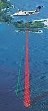
6 or points per second for acquisition of bathymetry data, and 64,000 Hz or points per second for acquisition of topographic data. This type of hybrid system means greater project utilisation over both topographic and bathymetric projects. Compared to conventional hydrographic survey methods, and despite the high cost of acquiring LiDAR bathymetry systems, the methodology offers economies both in operational cost and productivity increases. Due to size, weight and power requirements, bathymetry systems are generally flown from fixed wing aircraft, typically a Piper Aztec or Aero Commander 690. As an illustration, see figure 1 following. Figur 3 Optech SHOALS (Courtesy Optech Systems) Figure 1 Airborne LiDAR bathymetric system An integrated digital camera provides geo-referenced images of the area being flown, this not only makes data processing and editing much simpler, as it provides additional information for object definition (e.g. 3
7 recognition of vessels, buoys and fish farms, etc) it also provides additional data products. Previously, separate airplanes had to be mobilised in order to fly bathymetric LiDAR, topographic LiDAR and aerial photography. As a result, the range of data products now available from bathymetric LiDAR surveys operations is increasing rapidly. Bathymetry LiDAR data is generally acquired from a flying height of m, with horizontal positioning being achieved using DGPS or Kinematic GPS solutions. Operations are very much dependent upon clarity of the water being surveyed. Waves, rapids, algae bloom and general water turbidity can adversely affect LiDAR performance. The prevailing meteorological conditions and water clarity are therefore key considerations to any bathymetric LiDAR survey. The acquisition of LiDAR data, whether topographic or bathymetric, requires a robust quality assurance system to ensure integrity and accuracy of the acquired soundings. Standard procedures can apply though in practice each project benefits from a customized quality plan appropriate to the project task Airborne bathymetric LiDAR deliverables Current deliverables include XYZ point files Bathymetric DEM Topographic DEM Integrated Bathymetric / topographic DEM Contours Cross sections Plan profiles Slope Maps Smooth Sheets Colour coded Bathymetry Sun- illuminated Bathymetry Sea bed Imagery Integrated LiDAR & Multibeam Echo Sounder Bathymetry Digital Imagery Photo-Mosaics Fly through Movies Hyperspectral Camera for sea bed Classification (Optech) 4

8 3. The Benefits of Airborne Laser Bathymetry The advantages of Airborne Laser bathymetry systems are very evident when a large-scale bathymetric survey is to be undertaken. Speed of collection is the single biggest advantage LiDAR has over all other hydrographic tools, in the following section we will look at cost effectiveness combined with repeatability, seamless data collection of both hydrographic and topographic data, the ability of the systems to survey hazardous areas, acquisition by night and habitat mapping. 3.1 Speed of data collection cost effectiveness A shallow, 10 metre MBES (multibeam echo sounder) survey acquires approximately 2 km 2 of survey data in a 12-hour period. In comparison, a LiDAR survey a plane will make one 5-6 hour flight per day and could cover approximately 62km 2 of the same survey. However bathymetric LiDAR surveys in Ireland conducted from Clew bay in 2002 to Bantry Bay in 2006 (by Tenix LADS), has shown that due to the complex nature of our coastline and low cloud etc we can generally expect to survey between 27 km 2 and 30 km 2 per day, this is with a point spacing of 5m and 200% coverage. INFOMAR aims to gather up to 7000 km 2 of shallow water bathymetric survey data in the next seven years. If we take a cost figure of 1,000 per 1 km 2 (from Irish National Seabed Survey) for MBES in shallow water and apply it to 1000km 2 of survey area acquired with MBES, costs come in at 1 million. Include 20% for weather downtime and the cost rises to 1.2 million. Include mobilisation and processing and the costs rise to almost 1.4 million. Recent tenders (2006) for a shallow water 1000 km 2 bathymetric LiDAR survey came in at circa 1 million. If we look at the same 1000 km 2 survey in terms of time, an inshore MBES survey would take 500 days, 20% weather downtime and we are looking at 600 survey days, the same survey with LiDAR will take 16 flights, allowing for weather and environmental constraints this would take 36 days to achieve 200% coverage which will achieve IHO Order 1. Figure 2 following illustrates LiDAR coverage verses Multibeam to illustrate the point made on the speed of data collection above. Figure 2 Shallow water LiDAR vs. Multibeam 3.2 Repeatability 5

9 With the speed at which surveys can be collected, consecutive surveys can be compared to monitor changes in bathymetry and coastal topography that occur over time, such as beach and cliff erosion and storm damage. Airborne Laser Bathymetry is ideally suited to undertake repeat surveys. 3.3 Ability to survey a seamless transition zone A significant advantage of bathymetric laser systems is its ability to working in dual mode, i.e. surveying very shallow water in less than 10m, moving across to the shoreline and up onto topographic elevation. There is no degradation in vertical accuracy, no change in sounding density and no adjustment in aircraft track. This leads to a seamless survey data set for the entire coastal region. 3.4 Ability to survey shallow, rocky and hazardous areas Because LiDAR is non-intrusive, remote shallow waters with extreme hazards as is often the case on the west coast of Ireland, can be surveyed without risk to survey vessel, personnel or the environment. 3.5 Acquisition by night Acquisition of bathymetry data can be done by day or by night, however if surveying at night one would loose the ability to use digital photography to aid feature detection. 3.6 Habitat Mapping Backscatter data or reflectance data is measurable and can be used to identify sea floor features to aid habitat mapping. This would be extremely useful for projects such as MESH, the European mapping program for seabed habitats. The processing software used by the bathymetric LiDAR systems can use reflectance data to generate the Image shown in Figure 3 below. Figure 3 3-D reflectance imagery data. In addition a Hyperspectral camera can be added to both the Shoals or Haw Eye systems, this will allow for true bottom type classification and benthic habitat mapping. 6

10 Figure 4 Reflectance and Hyperspectral data combined 7

11 4. The Limitations of Airborne LiDAR Bathymetry 4.1 Water Clarity The primary restriction on the effectiveness of airborne LiDAR bathymetry is water clarity. The maximum depth penetration of LiDAR systems is constrained by water clarity. During 2004, a feasibility study was commissioned by the UK Hydrographic Office to address the suitability of LiDAR systems to UK waters. See Appendix 3 for the report. As water clarity plays such an important role in the effective collection of bathymetric LiDAR data, the desk study examined the clarity of UK waters. A full set of secchi observations (disappearance depths) were made available for the desk study by the UKHO and the UK environmental agency. The assumption is made that if reasonable depths can be achieved then LiDAR bathymetry systems are suited to operating in UK waters. Secchi observations are a spot sample of the water clarity under a certain set of wind, sea and turbidity conditions. As a general rule, LiDAR depths equate to 2-3 times the observed secchi depth. Generally, IHO Order 1 coverage and accuracy is achieved to a depth twice the observed secchi depth. Therefore LiDAR depths are calculated as 2 times secchi depth. For example if we measure water clarity with a secchi disk as being 10m we can assume quality data to 20m surveying with a LiDAR bathymetry system. Figure 5 Water clarity measurements with a secchi disk The issue of water clarity is a study in itself where, secchi, transmissometer, aerial and satellite data can all be combined to provide information on water clarity. In addition water clarity is a function of tidal streams and metrological factors. The UKHO report concluded that LiDAR surveying was feasible in areas such as the NW coast of Scotland, though this is a broad statement; this area similar to our own western seaboard in terms of water clarity. LiDAR surveying was feasible in 10 20m in winter and spring and 20 30m in summer and autumn. LiDAR surveys on our own western seaboard verify this, and to date have produced good results in 20 25m of water during late summer. 4.2 Object detection and Depth accuracy 8

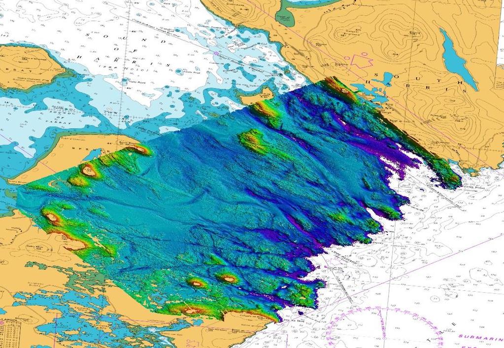
12 In general, a LiDAR seabed survey is well defined but small features (up to 3 or 4m cubed) may well be missed. LiDAR data is considered poor for wreck visualisation. In a case study of a LiDAR survey in the Sound of Harris, Scotland, it was established that full IHO Order 1 object detection was achievable only with additional multibeam survey data over complex areas, plus a diver examination. The following example shows a comparison of multibeam (Reson 8125) data and LiDAR data over a submerged crane. As can be seen from the figure 6 below, LiDAR is very poor at object detection especially where structures may have holes or gaps. The data was collected on a multibeam / LiDAR comparison study undertaken by NOAA in Eastern Long Island Sound in January Data was collected with a 3X3 shot spacing and 200% coverage. Figure 6 Object detection Multibeam vs LiDAR data In a case study by UKHO in the sound of Harris, LIDAR achieved 99% of what was actually required and detected rocks and identified places where kelp may hide rocks. In navigable channels, however multibeam was added to the data set to ascertain absolute least depth. Figure 7 below shows LiDAR data, which has defined the general area well but reports deeper depths. Circled in red is a shoal area of 0.9m, picked up by singlebeam, LiDAR shows the same feature as 1.5m. Figure 7 Depth accuracy of LiDAR vs singlebeam echosounder 9
13 5. LiDAR data and IHO Standards The International Hydrographic Office in Monaco set the standards worldwide for Hydrographic surveys. Mr. Chris Howlett (UKHO) currently chairs a working group that is looking at standards for LiDAR data. The two standards that we should be concerned with are IHO Order 1 and IHO Special Order. While no official IHO documents on LiDAR data have been published, conversations with UKHO verify that LiDAR is widely accepted as an excellent tool for the collection of large-scale bathymetric data. However it is not without its limitations and these are mainly based around object detection, as discussed in section 4.2. It is for this reason that the IHO standards are so important when assessing the accuracy of LiDAR data. All three systems in section 7, on the market claim to survey to IHO order 1, however it should be noted that this is in ideal water clarity conditions. It is interesting to note however is that only one system, the Hawk Eye, which is the system used by UKHO claims special order in shallows. 5.1 Navigational Accuracy As discussed above there are two sets of standards that we should be aware of for Bathymetric LiDAR namely IHO Order 1 and IHO Special Order Order 1 Order 1 hydrographic surveys are intended for harbours, harbour approach channels, recommended tracks, inland navigation channels, and coastal areas of high commercial traffic density where underkeel clearance is less critical and the geophysical properties of the seafloor are less hazardous to vessels (e.g. soft silt or sand bottom). Order 1 surveys should be limited to areas with less than 100 m water depth. Although the requirement for seafloor search is less stringent than for Special Order, full bottom search is required in selected areas where the bottom characteristics and the risk of obstructions are potentially hazardous to vessels. For these areas searched, it must be ensured that the sounding equipment can discern cubic features greater than 2 m up to 40 m water depth or greater than 10% of the depth in areas deeper than 40 m Special Order Special Order hydrographic surveys approach engineering standards and their use is intended to be restricted to specific critical areas with minimum underkeel clearance and where bottom characteristics are potentially hazardous to vessels. These areas have to be explicitly designated by the agency responsible for survey quality. Examples are harbours, berthing areas, and associated critical channels. All error sources must be minimized. Special Order requires the use of closely spaced lines in conjunction with side scan sonar, multi-transducer arrays or high-resolution multibeam echosounders to obtain 100% bottom search. It must be ensured that cubic features greater than 1m can be discerned by the sounding equipment. The use of side scan sonar in conjunction with a multibeam echosounder may be necessary in areas where thin and dangerous obstacles may be encountered. While possibly almost all of the Bathy LiDAR data to be acquired will fall under Order 1, because of the object definition issues associated with LiDAR data it may be prudent to collect LiDAR data to special order in shallows. 10
14 Order IHO Special IHO 1st Examples of Typical Areas Harbours, berthing areas, and associated critical channels with minimum underkeel clearances Harbours, harbour approach channels, recommended tracks and some coastal areas with depths up to 100 m Horizontal Accuracy (95% Confidence Level) Depth Accuracy for Reduced Depths (95% Confidence Level) 100% Bottom Search System Detection Capability 2 m 5 m + 5% of depth a = 0.25 m b = Compulsory Cubic features > 1 m a = 0.5 m b = Required in selected areas Cubic features > 2 m In depths up to 40 m Maximum Line Spacing Not applicable, as 100% search compulsory 3 x average depth or 25 m, whichever is greater Table 1 IHO Order Specifications 11
15 6. Synopsis of available systems Manufacturer & System Optech Shoals 1000T Hydrographic Topographic Measurement Rate 1,000 Hz 10,000 Hz & Operating Altitude Depth Measurement Accuracy Min & Max Depth m IHO Order 1 0.2m / 50m Typical Swath Width 215m (@ 4x4) Coverage 4x4 Alt 400m 50 km Kts Sounding Density / Point Spacing Metres 2x2, 3x3, 4x4, 5x5 Power Requirements 28VDC Weight 209 kg Optech Shoals 3000T AHAB Hawk Eye II 3,000 Hz 20,000 Hz 4,000 Hz 64,000 Hz m IHO Order 1 0.2m / 50m m IHO Order 1 and special Order in shallows 0.2 / 50m 300m (@4x4) 175 m (@2.5 x 2.5) 123 km Kts 20-80km 124 kts 2x2, 3x3, 4x4, 5x5 Programmable from 0.5x0.5 to 3x3 28VDC 217 Kg 45 28VDC 175 Kg Manufacturer & System Optech Shoals 1000T Optech Shoals 3000T AHAB Hawk Eye II Cost Topographic Laser Support & Maintenance Agreement Ongoing Support after Year 1 Euro 2.76 mil 1 Year 240K to 400k Euro 3.55 mil 1 Year 240K to 400k Lee Time for Delivery Months Months Euro 2.80 mil 1 Year 300K months Hperspectral Camera for seabed Classification Yes CASI K Yes CASI K Yes Itres CASI Installation on plane 2 Hours Yes 2 Hours Yes 1 Hour Yes Kinematic GPS 12
16 13


17 7.1 Available systems 7.2 System 1 Airborne Hydrography AB Hawk Eye II Overview The Hawk Eye II is an Airborne Laser Bathymetry and Topography System (ALBTS), using two Class 4 lasers (EN 60825). It can gather both bathymetric depths and topographic elevations in the same coordinate framework in one mission. The system is combined with a geo-referenced high-resolution digital camera sighted co-axially with the laser optics. The system is capable of meeting IHO Order 1 requirements and IHO Special Order requirements in shallow depths. Figure 8 Hawk Eye system principle The Hawk Eye II system can provide seamless coverage from a single survey of a coastal area, including land, shoreline and the adjacent water. The figure below shows both Hydrographic and Topographic data and images surveyed in the same mission. Images are tiled and used as texture on the 3D-model from the hydrographic and topographic data. Figure 9 Seamless Hawk Eye survey 14

18 7.2.2 Top level system architecture - Hawk Eye II The top-level system architecture of the Hawk Eye II is shown in Figure 10 below. Figure 10 Hawk Eye Top Level System Architecture The Survey System is the airborne part of the Hawk Eye II. The functions of the Survey System are surveying, control, monitoring and data storage. The operators console contains all of the necessary functionality to control the operation of the system with a single operator (two recommended for longer flights and for training purposes). The laser is certified to be eye-safe during normal operations but the system has a built in feature to automatically shut off the laser if it is not in an eye-safe mode or area. The following picture, Figure 11, shows the Survey System of the Hawk Eye II. The system is relatively small and lightweight, weighing in at 175kg. 15

19 Figure 11 The Hawk Eye Survey System The aircraft installation kit provides the interface between the Survey System and the aircraft. The kit consists of electrical cabling, pilot monitor interface cables, mechanical mounting adapters and, where appropriate covers/hoods and the like. While aircraft/platform specific, the installation kit is simple allowing the Hawk Eye II System to be changed in and out of an aircraft in about 3 hours. The following picture, Figure 12, shows the complete airborne element (single operator configuration) installed in an Aero Commander 690. Points to note are the relative small size of the complete system (recognising the small size of the Aero Commander aircraft), the simple interfaces (attachment to the standard seat rails) and the standard laptop operator s console. 16


20 Figure 12 The Hawk Eye system installed in an Aero Commander 690. The Ground Station consists of the software environment for the planning of the surveys and the subsequent post-survey data analysis and reduction. The Ground Station software can be run on standard commercial PCs. 7.3 System 2 & 3 Optechs SHOALS 1000T and 3000T The SHOALS-1000T and 3000T are airborne laser bathymetry survey instruments for shallow water and coastal regions. Like the Hawk Eye it is coupled with a fully integrated flight planning and data processing software subsystem. Both systems are also offered without the topographic laser the SHOALS 1000 and 3000 systems. The current SHOALS 1000T can measure 1000 water depth measurements per second and 10,000 measurements per second to land and it incorporates an integrated RGB digital camera. As illustrated in the comparison table of the systems at the beginning of Section 7, the primary difference between the 1000T and 3000T is the measurement rate. The 3000T system measures at 3,000 Hz in hydrographic mode and 20,000 Hz in topographic mode, while the 1000T system measures at 1,000 Hz in hydrographic mode and 10,000 Hz in topographic mode. Increasing the measurement rate allows the acquisition of even more detailed & dense data. The shoals systems consist of a sensor head, control rack, laser and operator display, see Figures 13 & 14 following. At a total weight of 200kg they are designed to fit most small twin-engine aircraft. 17
. Before flight operations, survey projects are created and individual missions planned in the GCS.")
21 Figure 13 Shoals system sensor head, control rack and laser Figure 14 Shoals 1000T installed in a small aircraft SHOALS-1000T survey operations are synchronised by the fully integrated SHOALS-1000 Ground Control System (GCS). Before flight operations, survey projects are created and individual missions planned in the GCS. Mission plans are uploaded to the SHOALS airborne computer for survey flights. The SHOALS-1000T and 3000T collect data with a high accuracy laser, mounted in the aircraft floor. The laser scans beneath the aircraft, sending out pulses in a swath over which the position of the water surface and sea floor is measured. To correct for the aircraft's movements, an Inertial Reference System (IRS) measures the motions of the aircraft. This data is used for real-time pitch and roll compensation, and recorded for post processing. A GPS receiver records the aircraft's position simultaneously. The laser pulse, waveforms, scan angle, GPS data and IRS data are combined to produce real-time and post-processed sounding positions or terrain elevations. The raw SHOALS-1000T sensor data collected by the airborne system is stored on mirrored removable hard drives, along with mission planning information and mission log information. The airborne data is then downloaded from the removable hard drives and processed in the SHOALS Ground Control Software. The GCS includes a fully integrated third-party software suite, IVS Fledermaus, to edit and clean the 3D data, this allows for the creation of a surface model to see a particular feature in the data. Figure 15 below shows a feature floating on the water surface; by calling on the data from the digital camera the feature can be identified as fish traps. 18

22 Figure 15 The Importance of an Integrated Digital Camera 19
23 8. World Applications of Bathymetric LiDAR Mapping The U.S. Army Corps of Engineers (USACE) has owned a SHOALS bathymetric mapping system for many years and contracts its operation and management to a commercial survey company, Fugro Pelagos. The U.S. Navy owns this system and Fugro Pelagos contract has been with the U.S. Navy's Naval Oceanographic Office from June Similarly in March 2004, Airborne Hydrographic AB and the UK Hydrographic Office joined forces and established a LiDAR operating and management company, Admiralty Coastal Surveys, to conduct bathymetric LiDAR surveys with the Hawk Eye II system. Tenix LADS owns and operates the Laser Airborne Depth Sounder (LADS) and has been conducting international bathymetric LiDAR survey operations since the late 1990 s. NOAA, the National Oceanic and Atmospheric Administration (U.S.) acquires LiDAR data, both for topographic and bathymetric mapping NOAA collaborates with USACE in its SHOALS program and uses this system for U.S. coastal mapping. The market for airborne LiDAR bathymetry (ALB) however is limited, as indicated by the small number of service providers and users, and although a commercial market can be identified, applications have been generally restricted to government mapping programs. Although mobilization and operating costs are high, ALB data acquisition is much more economic than a ship platform for large area mapping programs. In area coverage over shallow waters, ALB bathymetric systems are thirteen times faster than conventional MBES survey techniques. Also, LiDAR requires less people, a typical crew comprising of one air operator and two data processors, though one may also be the hydrographer. Therefore, a survey crew need only comprise two or three people per shift/per day. The U.N. convention, UNCLOS 76, allows countries to re-define their seaward national boundaries, thus providing a legal mechanism whereby a nation can extend its claims beyond the traditional 200-mile limit. According to the National Environment Research Council, this could cover as much as seven million km 2. Consequently, many countries now have a vast economic interest at stake in mapping these new legal boundaries. Both Optech and Tenix LADS report an increase in interest for coastal mapping from naval and national hydrographic agencies throughout the world, and as the trend is for government organisations to outsource survey services to commercial organisations, this is expected to offer increased opportunities to the private sector in the future. An example of the trend to privatisation is the U.K. Civil Hydrographic Program (CHP), which is funded by the Maritime and Coastguard Agency (MCA). The MCA is one component of the U.K. strategy to acquire and process data for maintenance of the British Admiralty charts. The U.K. Hydrographic Office (UKHO), based in Somerset, audits survey operations. The UKHO reviews and validates the survey data and results before accepting them for updating the Admiralty chart base. According to research carried-out by TMSI, (UK business development consultancy) at least 17 national mapping agencies have now used or are considering the use of commercial Airborne LiDAR bathymetric services. In Norway, the Norwegian Hydrographic Department has outsourced its territorial hydrographic data acquisition to BLOM ASA, which has worked with Tenix LADS to complete about 7,000 km 2. of bathymetric LiDAR mapping. The U.S. has an on-going charting program using the government-owned, commercially operated SHOALS system and more recently, with the Tenix LADS system. In 2003, the U.K. Hydrographic Office, together with the MCA and the Environment Agency, undertook an 150K desk study and field trials of Airborne LiDAR Bathymetry in the Integrated Coastal Hydrographic Project or ICH. This project was designed to test the suitability of LiDAR for bathymetric surveys in water depths up to 12 meters, particularly around the coast of Scotland, which, according to the Hydrographic Office, has been overlooked for many years. The trials took place in Wembury Bay near Plymouth, Devon, over sites where there was existing survey data from multibeam echo sounders (MBES) that were used for comparison. The LiDAR trials were conducted successfully to IHO Order 1 standards by Tenix LADS, which led to Tenix LADS 20
24 performing two further surveys in the Hebrides in In March 2004, the UK Hydrographic Office formed a Joint Venture Admiralty Coastal Surveys - with Swedish company Airborne Hydrography AB. Admiralty Surveys now manages and operates a Hawk Eye II LiDAR system. The Irish National seabed survey, a joint venture by the Marine Institute and Geological Survey of Ireland (GSI) was a seven-year survey of Ireland s seabed. This project, valued at nearly 30 million was completed in March Data was gathered primarily using multibeam echo sounders to survey an area of 525,000 km 2. In June 2002, GSI conducted a trial of the Tenix LADS system, which was carried-out in Clew Bay, County Mayo, a location chosen for water clarity as well as suitable water depth. Over a two-day period, flying eight hours a day, the LADS system successfully acquired 50 km 2 of data. According to the GSI, the data acquired was of excellent quality and was been submitted to the U.K. Hydrographic Office for inclusion in its database to update the century-old charts of the area. The U.K. Hydrographic Office was reported to be very satisfied with the quality of the data and as a result of these trials, GSI contracted Tenix LADS for a further two small area surveys each of between km 2 of bathymetric mapping. With the success of the Irish National seabed survey, a successive project, INFOMAR is underway. INFOMAR started in 2006 and is a 20 Year survey program, which has secured funding to INFOMAR aims to survey up to 7000 km 2 of inshore coastline using marine LiDAR systems. The first of these LiDAR surveys is currently underway by Tenix, with the areas of Dingle, Bantry and Dunmanus Bays being surveyed a total survey area of 789 km 2 at a cost of almost 1 million. Although there appears to be a growing awareness and acceptance that LiDAR bathymetry can produce a very cost-effective alternative to conventional vessel-based MBES surveys, there are concerns. Whilst still considering LiDAR for future use, the New Zealand National Hydrographic Authority found from its experience with both the LADS and SHOALS systems that the acquired data did not meet IHO S44 Standards without additional fill-in work from surface vessel MBES. Another key issue and concern is water clarity (turbidity), especially in the northern hemisphere. This leads to many agencies erring on the side of caution in specifying or even considering Airborne LiDAR Bathymetry. Tenix LADS has had to perform several tests and trials, not necessarily to prove the technology, but to ensure that water turbidity did not prevent or severely limit data acquisition. Thales GeoSolutions, acquired in 2003 by the international Fugro group, completed a hydrographic and topographic LIDAR survey with the SHOALS-1000T system in October 2003, which it claimed was the first time that SHOALS-1000T had been used for commercial applications. In addition, this was the first time that hydrographic and topographic LiDAR data had been collected from the same airborne sensor. The system toggles between the two modes in mid-flight at the switch of a button and also comes fitted with a coregistered digital camera. The project specified the collection of data on the north-eastern United States coast in order to determine the existing conditions of harbours and harbour entrances, mainly focusing on the conditions of jetties, breakwaters and near shore bathymetry. The lower cost of LiDAR creates new applications that would not otherwise be considered using conventional means. One example is the ability to gather bathymetry data on a regular basis to monitor changes in the seabed and coastline. The U.S. Army Corps of Engineers is performing regular surveys of a 500- mile stretch of the Gulf of Mexico coastline, to monitor sand movements. This work was previously undertaken once a year from a conventional hydrographic survey vessel. Now, because of the short data acquisition time and subsequent lower cost of LiDAR, the survey can be repeated two or three times a year. Other applications for bathymetric LiDAR are emerging, but are still in the domain of government agencies such as military, or in the U.S., state and local governments, that have in the past used ALB for mapping coastal zones, primarily to monitor beach erosion. Commercial applications have not yet developed, largely due to cost, but probably more to lack of opportunity in so much as there are few commercial needs for large area bathymetric mapping. 21
25 9. Market Analysis In the Bathymetry Systems market, there are only two manufacturers, Optech with their Shoals systems and Airborne Hydrography AB with the Hawk Eye II system. The services market consists of three bathymetry LiDAR survey operators, Admiralty Surveys operating the Hawk Eye II, Fugro Pelagos operating the Shoals 1000T system and Tenix LADS operating the LADS system. 9.1 Manufacturing Market There are two companies globally manufacturing and selling LiDAR Bathymetry systems, namely Airborne Hydrography AB based in Sweden and Optech based in Canada Airborne Hydrography AB (Sweden) Development of Swedish Airborne Laser Bathymetry Systems started in the 1980s by the development of the Flash system within the Swedish defence research agency. At that time the primary driver for the technology was submarine hunting. Sweden had several indications of foreign submarine activities within its archipelago in the 1980s. The most famous is the incident of the grounding of the Russian submarine U137 in Karlskrona In the beginning of the 1990s the Saab group received the commission to develop a replacement for the Flash system, and the first Hawk Eye system took form. Two Hawk Eye systems were delivered during 1994 and 1995, one to the Swedish navy and one to the Swedish maritime administration. The submarine activities decreased during the 1990 s and the systems primary use became Hydrographic surveying. One of the systems was sold to the Indonesian Navy in the late 1990 s. The other system was operated by the Swedish maritime administration until In 2002 Saab sold the products rights to three former Saab employees that had been in charge of the development. A new company, Airborne Hydrography AB (AHAB), was formed. The new owners had the vision to create the next generation Hawk Eye. The first Hawk Eye II system was delivered during autumn 2005 to Admiralty Coastal Surveys who provide worldwide survey services with the Hawk Eye II Optech (Canada) Canadian based Optech is a privately owned company with 160 employees and annual revenues in the order of US$18m with a reported 20% annual growth. Optech manufacturers a range of laser devices including single beam laser altimeter systems for determining accurate (5cm) altitude, three-dimensional ground lasers for high resolution engineering surveys and metrology, and both topographic and bathymetric Airborne LiDAR systems. Optech has been in the in the bathymetric LiDAR systems business since The original bathymetric LiDAR system, the Larsen 500, was sold to the Canadian Hydrographic Service in This was followed by the sale of a SHOALS-200 to the U.S. Army Corps of Engineers in 1993 (operated by Fugro Chance). This system was upgraded to a SHOALS-400 in 1998 and in February 2003, the SHOALS-400 was finally retired and in August of the same year it was replaced with CHARTS, which is the United States Navy's name for their SHOALS-1000T system. The U.S. Navy owns this system and Fugro Chance's (now Fugro Pelagos) contract has been with the U.S. Navy's Naval Oceanographic Office since June In February 2003, a SHOALS-1000T system was sold to the Japanese Coastguard. The most recent Optech sale was to the US Navy in January 2005 the SHOALS 3000T 3KHz/20KHz system. 22
26 9.2 Services Market The services market consists of three companies, Admiralty Coastal Surveys, Fugro Pelagos and Tenix LADS Admiralty Coastal Surveys Admiralty Coastal Surveys was formed in 2004 as a joint venture between the UK Hydrographic Office, Airborne Hydrography AB and Topeye AB of Sweden. The Hawk Eye II system was developed from the original Hawk Eye system sold to the Swedish Navy in 1994 (by Optech) Fugro Pelagos Fugro Pelagos operate a Shoals 1000T system from Optech. The US Army Corps of Engineers (USACE) own this Shoals system and contract its operation and management to Fugro. To confuse the issue, USACE have renamed their Shoals 100T system to CHARTS. Fugro has been operating ALB systems since 1993 and over the past decade have performed over 435 ALB surveys worldwide Tenix LADS Tenix LADS Corporation owns and operates the Laser Airborne Depth Sounder (LADS). The LADS Mk II, system is mounted in a de Havilland Dash 8-202, to provide contract survey services to governments and industrial customers. Tenix has a significant track record in bathymetric LiDAR surveys. The original LADS has been in routine survey operation with the Royal Australian Navy (RAN) Hydrographic Service since February 1993, and has surveyed over 85,000 km 2 (29,000 sq nm). LADS has also been used for survey operations in Finland, the United States, the United Kingdom, Norway, New Zealand and the Middle East, particularly the Gulf States. 23
27 10. References TMS International The Global Market for Airborne LiDAR Systems and Services Fugro Pelagos Proposal for INFOMAR Bathymetric LiDAR ITT Tenix LADS Response to ITT for Bathymetric LiDAR Airborne 2006 Company Literature and Appendix 1 Optech 2006 Company Literature and Appendix 2 Tenix LADS Corporation April Bathymetric Lidar Feasibility Study for UK Waters on behalf of UKHO. Appendix 3 International Hydrographic Office 4 th Edition April Publication No. 44 Standards for Hydrographic Surveyors Special 24
THE CHALLENGES OF A LARGE-AREA BATHYMETRIC SURVEY
 THE CHALLENGES OF A LARGE-AREA BATHYMETRIC SURVEY Agenda: - Introduction - Tender - Project Planning - Survey - Processing - Delivery - Conclusion 2 Introduction We know less of the oceans at our feet,
S-44 edition 5 The IHO s New Standard For Hydrographic Surveys Chris Howlett Head of Seabed Data Centre United Kingdom Hydrographic Office
 S-44 edition 5 The IHO s New Standard For Hydrographic Surveys Chris Howlett Head of Seabed Data Centre United Kingdom Hydrographic Office Chairman of IHO Working Group that created S-44 edition 5 S-44
Utilizing Vessel Based Mobile LiDAR & Bathymetry Survey Techniques for Survey of Four Southern California Breakwaters
 Utilizing Vessel Based Mobile LiDAR & Bathymetry Survey Techniques for Survey of Four Southern California Breakwaters Western Dredging Association: Pacific Chapter September 2012 Insert: Pipe Location
Challenges in determining water surface in airborne LiDAR topobathymetry. Amar Nayegandhi, Dewberry 15 th Annual JALBTCX Workshop, June 11 th 2014
 Challenges in determining water surface in airborne LiDAR topobathymetry Amar Nayegandhi, Dewberry 15 th Annual JALBTCX Workshop, June 11 th 2014 Why topobathy LiDAR? Complements acoustic (multi-beam sonar)
INTERNATIONAL HYDROGRAPHIC SURVEY STANDARDS
 INTERNATIONAL HYDROGRAPHIC SURVEY STANDARDS by Gerald B. MILLS 1 I. Background The International Hydrographic Organization (IHO) traces its origin to the establishment of the International Hydrographic
Geospatial Positioning Accuracy Standards Part 5: Standards for Nautical Charting Hydrographic Surveys - Public Review Draft
 Appendix B FGDC Hydrographic Accuracy Standard Geospatial Positioning Accuracy Standards Part 5: Standards for Nautical Charting Hydrographic Surveys - Public Review Draft Subcommittee on Marine and Coastal
Monetisation of sustainable business models for Satellite Derived Bathymetry
 Monetisation of sustainable business models for Satellite Derived Bathymetry Who are we? We are a UK & UAE based company specialising in satellite derived seabed & environmental mapping products We aim
LiDAR My favourite tool in the bag 2011 St Kitts & Nevis
 LiDAR My favourite tool in the bag 2011 St Kitts & Nevis Lt Cdr Rupert Forester-Bennett RN (ret d) December 5 th to 11 th 2011 Content Collection of geospatial data reasons Overcoming the White Ribbon
Emerging Subsea Networks
 THE FUTURE OF MARINE SURVEY APPLICATIONS FOR SUBMARINE CABLES Ryan Wopschall (Fugro) Email: rwopschall@fugro.com Fugro Pelagos, Inc. - 3574 Ruffin Road, San Diego, California 92123 USA Abstract: New advances
Hydrographic Surveying at The Port of London
 Hydrographic Surveying at The Port of London John Dillon-Leetch Port and Terminal Technology 2009 14 th October, Antwerp Overview Introduction Surveying the Thames Navigational Charting High Resolution
ICES Guidelines for Multibeam Echosounder Data (Compiled September 2006)
") ICES Guidelines for Multibeam Echosounder Data (Compiled September 2006) If you are considering producing a hydrographic survey please read the following information first. Your survey could be used to
ICES Guidelines for Multibeam Echosounder Data (Compiled September 2006) If you are considering producing a hydrographic survey please read the following information first. Your survey could be used to
Total Shallow-Water Survey Through Airborne Hydrography
 Total Shallow-Water Survey Through Airborne Hydrography Jennifer M. Wozencraft Joint Airborne Lidar Bathymetry Technical Center of Expertise US Army Corps of Engineers 109 St. Joseph Street Mobile, AL
Processing Lidar Data for Charting Applications Understanding the Trade-Offs and Challenges
 Processing Lidar Data for Charting Applications Understanding the Trade-Offs and Challenges A variety of acoustic and optical technologies are able to be used to survey shallow water areas. Due to the
BOTTOM MAPPING WITH EM1002 /EM300 /TOPAS Calibration of the Simrad EM300 and EM1002 Multibeam Echo Sounders in the Langryggene calibration area.
 BOTTOM MAPPING WITH EM1002 /EM300 /TOPAS Calibration of the Simrad EM300 and EM1002 Multibeam Echo Sounders in the Langryggene calibration area. by Igor Kazantsev Haflidi Haflidason Asgeir Steinsland Introduction
Tutorial for the. Total Vertical Uncertainty Analysis Tool in NaviModel3
 Tutorial for the Total Vertical Uncertainty Analysis Tool in NaviModel3 May, 2011 1. Introduction The Total Vertical Uncertainty Analysis Tool in NaviModel3 has been designed to facilitate a determination
PORTS AUSTRALIA. PRINCIPLES FOR GATHERING AND PROCESSING HYDROGRAPHIC INFORMATION IN AUSTRALIAN PORTS (Version 1.5 November 2012)
") PORTS AUSTRALIA PRINCIPLES FOR GATHERING AND PROCESSING HYDROGRAPHIC INFORMATION IN AUSTRALIAN PORTS (Version 1.5 November 2012) PREFACE These Principles have been prepared by the Hydrographic Surveyors
PORTS AUSTRALIA PRINCIPLES FOR GATHERING AND PROCESSING HYDROGRAPHIC INFORMATION IN AUSTRALIAN PORTS (Version 1.5 November 2012) PREFACE These Principles have been prepared by the Hydrographic Surveyors
Evaluation of the Klein HydroChart 3500 Interferometric Bathymetry Sonar for NOAA Sea Floor Mapping
 Evaluation of the Klein HydroChart 3500 Interferometric Bathymetry Sonar for NOAA Sea Floor Mapping Yuhui Ai, Straud Armstrong and Dean Fleury L-3 Communications Klein Associates, Inc. 11 Klein Dr. Salem,
Advantages of Using Combined Bathymetry and Side Scan Data in Survey Processing T.M. Hiller, L.N. Brisson
 Advantages of Using Combined Bathymetry and Side Scan Data in Survey Processing T.M. Hiller, L.N. Brisson EdgeTech, West WareHam MA, USA EdgeTech 6205 Combined Bathymetric and Side Scan Sonar EdgeTech
Design and Planning Considerations For a Seabed Survey
 Design and Planning Considerations For a Seabed Survey Vera Quinlan Hydrographer & Data Processor Seabed Survey Overview Survey Platform - What boat do I use? Survey Area / depth of water / objective &
High Precision Hydrography in Canada, the ST. Lawrence River Channel, HD Bathymetry, Production, Distribution and Updating
 High Precision Hydrography in Canada, the ST. Lawrence River Channel, HD Bathymetry, Production, Distribution and Updating Marc Journault Canada CHS, Louis Maltais Canada CHS, and Richard Sanfaçon Canada
Small Footprint Topo-Bathymetric LiDAR
 May 8, 2013 Small Footprint Topo-Bathymetric LiDAR PNAMP Remote Sensing Forum Russ Faux, Co-CEO, WSI Amar Nayegandhi, Manager of Elevation Technologies, Dewberry Colin Cooper, Senior Analyst, WSI Watershed
Scottish Hydro Electric Power Distribution Operation, Inspection, Maintenance and Decommissioning Strategy Bute Cumbrae Cable Replacement
 SHEPD Section ID 154 Scottish Hydro Electric Power Distribution Operation, Inspection, Maintenance and Decommissioning Strategy Bute Cumbrae Cable Replacement Contents Definitions and Abbreviations...
1 st Tidal and Water Level Working Group Meeting DHN, Niteroi, Brazil 31/03/09 02/04/09 Vertical Offshore Reference Framework (VORF) Chris Jones
 Chris Jones") 1 st Tidal and Water Level Working Group Meeting DHN, Niteroi, Brazil 31/03/09 02/04/09 Vertical Offshore Reference Framework (VORF) Chris Jones United Kingdom Hydrographic Office Presentation Structure
1 st Tidal and Water Level Working Group Meeting DHN, Niteroi, Brazil 31/03/09 02/04/09 Vertical Offshore Reference Framework (VORF) Chris Jones United Kingdom Hydrographic Office Presentation Structure
14/10/2013' Bathymetric Survey. egm502 seafloor mapping
 egm502 seafloor mapping lecture 10 single-beam echo-sounders Bathymetric Survey Bathymetry is the measurement of water depths - bathymetry is the underwater equivalent of terrestrial topography. A transect
Interferometric Swath Bathymetry for Large Scale Shallow Water Hydrographic Surveys
 Interferometric Swath Bathymetry for Large Scale Shallow Water Hydrographic Surveys Lisa N. Brisson 1, Damon A. Wolfe 1, Matthew Staley P.S.M. 2 1 EdgeTech 4 Little Brook Rd West Wareham, MA 02576 2 USACE
Multibeam and Laser: Combined High Resolution. Hydrographic Surveying for Civil Engineering Project Support
 Multibeam and Laser: Combined High Resolution Hydrographic Surveying for Civil Engineering Project Support John Dillon-Leetch,Port of London Authority Duncan Mallace, NetSurvey, UK Overview Introduction
BASELINE SURVEY, VISUAL - SITE SPECIFIC
 BASELINE SURVEY, VISUAL - SITE SPECIFIC Introduction As stated in SEPA s policy and in the Fish Farm Manual (1998), scientific data are required by SEPA in order to assess the existing condition on the
Uncertainty Estimates in Satellite Derived Bathymetry
 Uncertainty Estimates in Satellite Derived Bathymetry Richard Flemmings, TCarta #chcnsc2018 Introduction and Overview 1. TCarta 2. Satellite Derived Bathymetry Overview 3. Satellite Derived Bathymetry
Vieques Underwater Demonstration Project
 Vieques Underwater Demonstration Project NOAA Office of Response and Restoration National Ocean Service 2006-2007 2007 University of New Hampshire Joint Hydrographic Center 2006 Science Application International
Meeting the Challenges of the IHO and LINZ Special Order Object Detection Requirements
 Meeting the Challenges of the IHO and LINZ Special Order Object Detection Requirements Erik Hammerstad Kongsberg Maritime P. O. Box 111, N-3191 Horten, Norway erik.oscar.hammerstad@kongsberg.com Abstract
NEED FOR SUPPLEMENTAL BATHYMETRIC SURVEY DATA COLLECTION
 305 West Grand Avenue, Suite 300 Montvale, New Jersey 07645 Phone 201.930.9890 Fax 201.930.9805 www.anchorqea.com M EMORANDUM To: Caroline Kwan and Nica Klaber U.S. Environmental Protection Agency Region
Marine Renewables Industry Association. Marine Renewables Industry: Requirements for Oceanographic Measurements, Data Processing and Modelling
 Marine Renewables Industry Association Marine Renewables Industry: Requirements for Oceanographic Measurements, Data Processing and Modelling October 2009 Table of Contents 1. Introduction... 1 2. Measurements
Real Time Surveying GPS and HYDRO Software for Tide and Swell Compensation
 Real Time Surveying GPS and HYDRO Software for Tide and Swell Compensation by Mr Michael Walker, B.Surv. (Otago) HYDRO Division Trimble Navigation New Zealand Ltd. Abstract This paper focuses on the use
Certified Professionals in Hydrographic Solutions
 Certified Professionals in Hydrographic Solutions Client Satisfaction is our Deliverable Port of Brisbane Pty Ltd Port Surveys Certified Professionals in Hydrographic Surveying Tel +61 (0) 7 3258 4820
ScanFish Katria. Intelligent wide-sweep ROTV for magnetometer surveys
 ScanFish Katria Intelligent wide-sweep ROTV for magnetometer surveys User-friendly control and monitoring software solution The ScanFish Katria comes with the ScanFish III Flight software, which is an
RAMSTM. 360 Riser and Anchor-Chain Integrity Monitoring for FPSOs
 RAMS 360 Riser and Anchor-Chain Integrity Monitoring for FPSOs Introduction to RAMS Tritech s RAMS is a 360 anchor-chain and riser integrity monitoring system for Floating Production Storage and Offloading
Data Collection and Processing: Elwha Estuary Survey, February 2013
 Data Collection and Processing: Elwha Estuary Survey, February 2013 Ian Miller, WA Sea Grant Olympic Peninsula Field Office, 1502 E. Lauridsen Blvd #82, Port Angeles, WA 98362 immiller@u.washington.edu
Acoustic Pipeline Inspection Mind The Gap
 Acoustic Pipeline Inspection Mind The Gap Mike Liddell Chief Surveyor, Fugro Survey Limited UUVS @ Oceanology 2012 13 th March 2012 Contents Menu Introduction to Pipeline Inspection The Current Toolkit
Wade Reynolds 1 Frank Young 1,2 Peter Gibbings 1,2. University of Southern Queensland Toowoomba 4350 AUSTRALIA
 A Comparison of Methods for Mapping Golf Greens Wade Reynolds 1 Frank Young 1,2 Peter Gibbings 1,2 1 Faculty of Engineering and Surveying 2 Australian Centre for Sustainable Catchments University of Southern
Sontek RiverSurveyor Test Plan Prepared by David S. Mueller, OSW February 20, 2004
 Sontek RiverSurveyor Test Plan Prepared by David S. Mueller, OSW February 20, 2004 INTRODUCTION Sontek/YSI has introduced new firmware and software for their RiverSurveyor product line. Firmware changes
PACIFIC NORTHWEST TEST OF A HYDROGRAPHIC AIRBORNE LASER SCANNER
 PACIFIC NORTHWEST TEST OF A HYDROGRAPHIC AIRBORNE LASER SCANNER Green LiDAR Workshop June 3 7, 2012 Russell Faux, Principal Watershed Sciences, Inc. 517 SW 2 nd Street, Suite 400 Corvallis, OR 97333 541
Specifications for Synchronized Sensor Pipe Condition Assessment (AS PROVIDED BY REDZONE ROBOTICS)
") Specifications for Synchronized Sensor Pipe Condition Assessment (AS PROVIDED BY REDZONE ROBOTICS) A. Scope of Work The work covered by these specifications consists of furnishing all materials, labor,
Specifications for Synchronized Sensor Pipe Condition Assessment (AS PROVIDED BY REDZONE ROBOTICS) A. Scope of Work The work covered by these specifications consists of furnishing all materials, labor,
The Evolution of an Autonomous Unmanned Surface Vessel and Software for Hydrographic Survey
 The Evolution of an Autonomous Unmanned Surface Vessel and Software for Hydrographic Survey Paul Donaldson In 2017, Leidos, Inc. participated in both the Gulf of Mexico Unmanned Systems Operational Demonstration
INTERNATIONAL HYDROGRAPHIC REVIEW MAY 2015
 OPERATION TIRÚA: HYDROGRAPHIC VISION N.A. Guzmán Montesinos Naval Hydrographic Engineer Head of the Information Technology Department Head of the Chilean Tsunami Warning Center, Chile Abstract On 6 October
Bathymetry User Needs and Challenges in Australia and New Zealand
 Bathymetry User Needs and Challenges in Australia and New Zealand Nathan Quadros nquadros@crcsi.com.au Shallow Water Survey February 212 Background Recent significant investment in Bathymetric LiDAR acquisition
Paper for consideration by ENC Working Group. Use of AU6 ENC cells as an option for Bathymetric ENCs (benc)
") Paper for consideration by ENC Working Group Use of AU6 ENC cells as an option for Bathymetric ENCs (benc) Submitted by: Alvaro Sanchez (AHS) Executive Summary: Compilation of high density bathymetric
Paper for consideration by ENC Working Group Use of AU6 ENC cells as an option for Bathymetric ENCs (benc) Submitted by: Alvaro Sanchez (AHS) Executive Summary: Compilation of high density bathymetric
IHO SP 44 Standards for Hydrographic Surveys and the demands of the new century.
 IHO SP 44 Standards for Hydrographic Surveys and the demands of the new century. Dave Monahan, CHS, and D E Wells, Ocean Mapping Group, UNB Keeping any standard up to date is a never-ending task. For example,
An Integrated Marine Gradiometer Array System (MGA)
") An Integrated Marine Gradiometer Array System (MGA) For Detection and Location of Chemical and Conventional UXO/MEC in Shallow to Deep Marine and Freshwater Environments Introduction Tetra Tech EC, Inc.
An Integrated Marine Gradiometer Array System (MGA) For Detection and Location of Chemical and Conventional UXO/MEC in Shallow to Deep Marine and Freshwater Environments Introduction Tetra Tech EC, Inc.
Robin J. Beaman. School of Earth and Environmental Sciences, James Cook University, Cairns, Qld 4870, Australia.
 Robin J. Beaman School of Earth and Environmental Sciences, James Cook University, Cairns, Qld 4870, Australia. Email: robin.beaman@jcu.edu.au Seminar to SSSI Qld Hydrography Coping with Nature, Brisbane,
Recommended operating guidelines (ROG) for sidescan Sidescan sonar ROG in wrapper.doc English Number of pages: 9 Summary:
 for sidescan Sidescan sonar ROG in wrapper.doc English Number of pages: 9 Summary:") Title: Author(s): Document owner: Recommended operating guidelines (ROG) for sidescan sonar Dave Long (BGS) Dave Long (BGS) Reviewed by: Janine Guinan (MI) 07/09/07 Workgroup: MESH action: 2.1 Version:
Title: Author(s): Document owner: Recommended operating guidelines (ROG) for sidescan sonar Dave Long (BGS) Dave Long (BGS) Reviewed by: Janine Guinan (MI) 07/09/07 Workgroup: MESH action: 2.1 Version:
GNSS Technology for the Determination of Real-Time Tidal Information
 GNSS Technology for the Determination of Real-Time Tidal Information Benjamin Kidder C-Nav Positioning Solutions European region Outline of Topics Covered Introduction to Tides Past and Present Methods
Advanced PMA Capabilities for MCM
 Advanced PMA Capabilities for MCM Shorten the sensor-to-shooter timeline New sensor technology deployed on off-board underwater systems provides navies with improved imagery and data for the purposes of
Reply of Guyana Annex R2
 Summary of Findings: Analysis of Recent Shoreline Revisions to the This report assesses recent shoreline changes made to the 2005 edition of Dutch nautical chart NL 2218. This new edition is credited jointly
ENVIRONMENT AGENCY GREAT OUSE AND 100 FT DRAIN QUARTERLY BATHYMETRIC SURVEY DECEMBER 2013 SITE SURVEY REPORT NO. H6787
 ENVIRONMENT AGENCY GREAT OUSE AND 100FT DRAIN QUARTERLY BATHYMETRIC SURVEY DECEMBER 2013 NO. H6787 LONGDIN & BROWNING (SURVEYS) LIMITED CHERRY TREE HOUSE CARMARTHEN ROAD SWANSEA SA1 1HE H6787 1 Measured
NEW SURVEY MOTOR LAUNCHES FOR THE ROYAL AUSTRALIAN NAVY
 International Hydrographic Review, Monaco, LXVI(l), January 1989 NEW SURVEY MOTOR LAUNCHES FOR THE ROYAL AUSTRALIAN NAVY by Commander John LEECH, RAN (*) INTRODUCTION By any standards the task facing the
Potential applications of AUVs and Gliders in Offshore Windfarm Site Surveys
 Potential applications of AUVs and Gliders in Offshore Windfarm Site Surveys Dr James Hunt (National Oceanography Centre, Southampton) MREKE Internship in partnership with MARS at NOCS Introduction to
Introduction. VORF - Model Development and Principles. The required VORF model transformation accuracies were as follows:
 Introduction In 2006, the United Kingdom Hydrographic Office (UKHO) began testing of the Vertical Offshore Reference Frame (VORF), which had been developed on their behalf by the Department of Geomatic
Crowdsourced Bathymetry Data via Electronic Charting Systems
 Crowdsourced Bathymetry Data via Electronic Charting Systems Evan Robertson evan.robertson@noaa.gov Cooperative Institute for Research in Environmental Sciences (CIRES), University of Colorado, Boulder,
Release Performance Notes TN WBMS _R _Release_Presentation.pptx 22 September, 2014
 TN-140079-1.2 WBMS _R2014-06_Release_Presentation.pptx 22 September, 2014 Since the 2013-12 release, NORBIT has made tremendous improvements to both the functionality and performance of the WBMS systems.
A Wind Profiling Platform for Offshore Wind Measurements and Assessment. Presenter: Mark Blaseckie AXYS Technologies Inc.
 A Wind Profiling Platform for Offshore Wind Measurements and Assessment Presenter: Mark Blaseckie AXYS Technologies Inc. Any Sensor, Any Telemetry, Any Environment Founded in 1974 Part of the AXYS Group
FAI Sporting Code. UAV Class U. Section 12 Unmanned Aerial Vehicles Edition. Effective 1st January 2018
 FAI Sporting Code Section 12 Unmanned Aerial Vehicles UAV Class U 2018 Edition Effective 1st January 2018 Section 12 and General Section combined make up the complete Sporting Code for UAV FEDERATION AERONAUTIQUE
Coastal Engineering Technical Note
 Coastal Engineering Technical Note CETN VI-31 The SHOALS System - A Comprehensive Surveying Tool by Larry E. Parson and W. Jeff Lillycrop PURPOSE The U.S. Army Corps ofengineers (USACE) conducts extensive
Pathways Interns: Annika O Dea, Ian Conery, Andrea Albright
 1 REMOTE SENSING OF COASTAL MORPHODYNAMICS 237 237 237 217 217 217 2 2 2 8 119 27 252 174.59 255 255 255 163 163 163 131 132 122 239 65 53 11 135 12 112 92 56 62 12 13 12 56 48 13 12 111 Kate Brodie Brittany
IFREMER, Department of Underwater Systems, Toulon, France. L u c i e Somaglino, P a t r i c k J a u s s a u d, R o main P i a s co, E w e n Raugel
 F i r s t s e a t r i a l s w i t h E M 2 0 4 0 m u l t i b e a m s o u n d e r i n n o v a t i v e i n t e g r a t i o n o n H y b r i d R O V A r i a n e IFREMER, Department of Underwater Systems, Toulon,
The Role of Hellenic Navy Hydrographic Service in Preparing for the Olympic Games. Contents
 The Role of Hellenic Navy Hydrographic Service in Preparing for the Olympic Games by Commodore A. Sklavidis HN Cdr A. Mavraeidopoulos HN LCdr D. Evagelidis HN Ljg A. Michopoulos HN FIG Conference, Athens
REPORT DOCUMENTATION PAGE
 REPORT DOCUMENTATION PAGE Form Approved OMB No. 0704-0188 Public reporting burden for this collection of information is estimated to average 1 hour per response, including the time for reviewing instructions,
Utility of Airborne Lidar Bathymetry in Extreme Coastal Environments: Planning Considerations, Results and Lessons Learned
 Utility of Airborne Lidar Bathymetry in Extreme Coastal Environments: Planning Considerations, Results and Lessons Learned Don VENTURA, United States Fugro Pelagos Incorporated Topic: A: Innovations in
NOAA s Underwater UXO Demonstration Projects Vieques Island, Puerto Rico
 NOAA s Underwater UXO Demonstration Projects Vieques Island, Puerto Rico Vieques Restoration Advisory Board Meeting May 7, 2008 Jason Rolfe NOAA s Office of Response & Restoration NOAA s Underwater UXO
EMPA 2017 How can the S-102 Bathymetric Surface Product improve safety in navigation and pilotage?
 EMPA 2017 How can the S-102 Bathymetric Surface Product improve safety in navigation and pilotage? Operated by the Norwegian Mapping Authority, Hydrographic Service FREEDOM TO CHOOSE Content What is the
Airborne Lidar Bathymetry: The SHOALS System
 Airborne Lidar Bathymetry: The SHOALS System ABSTRACT by J.L. IRISH, J.K. McCLUNG, W.J. LlLLYCROP Joint Airborne Lidar Bathymetry Technical Center of Expertise US Army Engineer District Mobile CESAM-OP-J
OPERATIONS SEAFARER CERTIFICATION GUIDANCE NOTE SA MARITIME QUALIFICATIONS CODE. Deck: Chart Work
 Page 1 of 6 Compiled by Approved by Chief Examiner Syllabus Committee: 26 February 2013 OPERATIONS SEAFARER CERTIFICATION GUIDANCE NOTE SA MARITIME QUALIFICATIONS CODE Deck: Chart Work Page 2 of 6 COLUMN
Sonar Bathymetry: Waquoit Bay NERR
 Sonar Bathymetry: Waquoit Bay NERR Determining the Functional Shallow Water Limitation for an Arrival Based Sonar Frederick A. Hegg Teledyne Benthos, Inc. 49 Edgerton Drive North Falmouth, MA 02556 fhegg@teledyne.com
Hydrographic Surveying:
 Hydrographic Surveying: Specifications & Standards IHO USACE NOAA Captain Bob Pawlowski, NOAA (Ret), MNI History of Hydrography 13 th century first known chart Does not include Asia China and Japan 15
The MEDUSA Deep Sea and FUSION AUVs:
 1 The MEDUSA Deep Sea and FUSION AUVs: When Research and business get together EMRA 2017, Girona, Spain 15 May 2017 Bruno Cardeira/IST Deep Ocean Exploration -Why the effort? Portugal Exclusive Economic
Homework 2 Bathymetric Charts [based on the Chauffe & Jefferies (2007)]
![Homework 2 Bathymetric Charts [based on the Chauffe & Jefferies (2007)]](/thumbs/75/72427079.jpg "Homework 2 Bathymetric Charts [based on the Chauffe & Jefferies (2007)]") 1 MAR 110 HW-2 - Bathy Charts Homework 2 Bathymetric Charts [based on the Chauffe & Jefferies (2007)] 2-1. BATHYMETRIC CHARTS Bathymetric charts are maps of a region of the ocean used primarily for navigation
1 MAR 110 HW-2 - Bathy Charts Homework 2 Bathymetric Charts [based on the Chauffe & Jefferies (2007)] 2-1. BATHYMETRIC CHARTS Bathymetric charts are maps of a region of the ocean used primarily for navigation
Airborne Laser Bathymetry for Monitoring the German Baltic Sea Coast
 Airborne Laser Bathymetry for Monitoring the German Baltic Sea Coast J. NIEMEYER 1, T. KOGUT 1,2 & C. HEIPKE 1 ABSTRACT: Periodic monitoring of the sea bed is one of the most important tasks of the public
Paper for Consideration by HSSC8 Development of an Additional Bathymetry Layer standard based on S-57/S-52
 Paper for Consideration by HSSC8 Development of an Additional Bathymetry Layer standard based on S-57/S-52 Submitted by: CIRM, Germany, USA (NOAA) Executive Summary: Proposal for the standardization of
Plot the Path. Mary Anne Otten. lesson three
 Plot the Path Mary Anne Otten lesson three Subject/Grade: Grade 2, Math, Social Studies, Science Duration: one class period Materials needed: Per class: Day the Great Lakes Drained Away by Charles Ferguson
Optimizing Sound Speed Profiling to Meet TPU Requirements using a CAST Gauge
 Optimizing Sound Speed Profiling to Meet TPU Requirements using a CAST Gauge (Computer Aided Sound speed Technology) Derrick R. Peyton, Steven Smyth, Arnold Furlong ODIM Brooke Ocean Jonathan Beaudoin
Windar Photonics Wind Sensor. Great at Control
 Windar Photonics Wind Sensor Version 1.0 2012 Contents Imagine Being Able to Predict the Wind 5-6 Wind Sensors in a New Light 7-8 You Harvest the Wind Better from the Top 9-10 Result of a Bright Idea 11-12
ZIPWAKE DYNAMIC TRIM CONTROL SYSTEM OUTLINE OF OPERATING PRINCIPLES BEHIND THE AUTOMATIC MOTION CONTROL FEATURES
 ZIPWAKE DYNAMIC TRIM CONTROL SYSTEM OUTLINE OF OPERATING PRINCIPLES BEHIND THE AUTOMATIC MOTION CONTROL FEATURES TABLE OF CONTENTS 1 INTRODUCTION 3 2 SYSTEM COMPONENTS 3 3 PITCH AND ROLL ANGLES 4 4 AUTOMATIC
Plot the Path into the Harbor
 Plot the Path into the Harbor By Mary Anne Otten, Rudyard Area Schools and Joan Chadde, Michigan Technological University Subject/Grade: Grade 3 6, Math, Social Studies, Science Duration: 35 minutes Lesson
General Dynamics Canada Whitepaper. Abstract
 Advanced Robotics for Next generation Mine Countermeasures Abstract Maritime mines are one of the most cost effective weapons in the naval arsenal. They deny access to coastal zones, thereby seriously
Where are the Bathymetric Hot-Spots?
 Where are the Bathymetric Hot-Spots? Dave Monahan Center for Coastal and Ocean Mapping University of New Hampshire If I win really BIG at the Casino tonight Every now and then, there are news stories of
DUKC Chart Overlay. Presentation to IHO TWL and DQ Working Groups Wollongong, March 2014
 DUKC Chart Overlay Presentation to IHO TWL and DQ Working Groups Wollongong, March 2014 Outline Who is OMC? DUKC description & methodology. DUKC Chart Overlay concept. Chart Overlay application example.
Digital Elevation Models
 Digital Elevation Models National Elevation Dataset 14-Oct-14 GEO327G/386G, UT Austin 1 Data Sets US DEM series 7.5, 30, 1 o for conterminous US 7.5, 15 for Alaska US National Elevation Data (NED) GTOPO30
MARINE NOTICE MARINE NOTICE. Marine Notice 11/2012 Supersedes 15/2010 and 7/2012. Guidance on ECDIS for ships calling at Australian ports 11/2012
 MARINE NOTICE MARINE 11/2012 NOTICE Marine tice 11/2012 Supersedes 15/2010 and 7/2012 Guidance on ECDIS for ships calling at Australian ports This notice aims to clarify some of the emerging issues relating
INTERNATIONAL HYDROGRAPHIC ORGANIZATION
 INTERNATIONAL HYDROGRAPHIC ORGANIZATION S-67 MARINERS GUIDE TO ACCURACY OF ELECTRONIC NAVIGATIONAL CHARTS (ENC) Edition 0.5 July 2017 Copyright International Hydrographic Organization 2017 This work is
Determination of Survey Boat Heave Motion with the Use of RTS Technique
 Environmental Engineering 10th International Conference Vilnius Gediminas Technical University Lithuania, 27 28 April 2017 http://enviro.vgtu.lt eissn 2029-7092 / eisbn 978-609-476-044-0 Article ID: enviro.2017.229
A PRACTICAL APPROACH TO QUALITY CONTROL AND QUALITY ANALYSIS OF DEPTH DATA
 A PRACTICAL APPROACH TO QUALITY CONTROL AND QUALITY ANALYSIS OF DEPTH DATA ABSTRACT Ulf Olsson, Mats Ericson, Stigbjörn Nilsson, Hans Öiås Hydrographic Office, Swedish Maritime Administration, Sweden Quality
An IOOS Operational Wave Observation Plan Supported by NOAA IOOS Program & USACE
 An IOOS Operational Wave Observation Plan Supported by NOAA IOOS Program & USACE R.E. Jensen, W.A. Birkemeier and W. Burnett JCOMM-Workshop on Wave Measurements from Buoys Wave Information to Application
RESOLUTION MSC.94(72) (adopted on 22 May 2000) PERFORMANCE STANDARDS FOR NIGHT VISION EQUIPMENT FOR HIGH-SPEED CRAFT (HSC)
 (adopted on 22 May 2000) PERFORMANCE STANDARDS FOR NIGHT VISION EQUIPMENT FOR HIGH-SPEED CRAFT (HSC)") MSC 72/23/Add.1 RESOLUTION MSC.94(72) EQUIPMENT FOR HIGH-SPEED CRAFT (HSC) THE MARITIME SAFETY COMMITTEE, RECALLING Article 28(b) of the Convention on the International Maritime Organization concerning
MSC 72/23/Add.1 RESOLUTION MSC.94(72) EQUIPMENT FOR HIGH-SPEED CRAFT (HSC) THE MARITIME SAFETY COMMITTEE, RECALLING Article 28(b) of the Convention on the International Maritime Organization concerning
FAI Sporting Code. UAV Class U. Section 12 Unmanned Aerial Vehicles Edition. Effective 1st January 2019
 FAI Sporting Code Section 12 Unmanned Aerial Vehicles UAV Class U 2019 Edition Effective 1st January 2019 Section 12 and General Section combined make up the complete Sporting Code for UAV FEDERATION AERONAUTIQUE
MARINE NOTICE MARINE NOTICE. Marine Notice 7/2012. Guidance on ECDIS for ships calling at Australian ports 7/2012
 MARINE NOTICE MARINE 7/2012 NOTICE Marine Notice 7/2012 Guidance on ECDIS for ships calling at Australian ports This notice aims to clarify some of the emerging issues relating to the carriage requirements
Technical Brief - Wave Uprush Analysis Island Harbour Club, Gananoque, Ontario
 Technical Brief - Wave Uprush Analysis RIGGS ENGINEERING LTD. 1240 Commissioners Road West Suite 205 London, Ontario N6K 1C7 October 31, 2014 Table of Contents Section Page Table of Contents... i List
STUDY REPORT W&AR-03 RESERVOIR TEMPERATURE MODEL ATTACHMENT B DON PEDRO RESERVOIR BATHYMETRIC STUDY REPORT
 STUDY REPORT W&AR-03 RESERVOIR TEMPERATURE MODEL ATTACHMENT B DON PEDRO RESERVOIR BATHYMETRIC STUDY REPORT DON PEDRO RESERVOIR BATHYMETRIC STUDY REPORT Prepared for: TURLOCK IRRIGATION DISTRICT MODESTO
An accident at sea, such as an
 Littoral water survey and security Surveying by Claude Cazaoulou, ECA More than 90% of international commercial exchange and 70% of annual world oil consumption are transported by sea. Millions of people
A real time vessel air gap monitoring system
 Journal of Physics: Conference Series A real time vessel air gap monitoring system To cite this article: D McStay and K Thabeth 2009 J. Phys.: Conf. Ser. 178 012038 View the article online for updates
from ocean to cloud PARAMETRIC SUB-BOTTOM PROFILER, A NEW APPROACH FOR AN OLD PROBLEM
 PARAMETRIC SUB-BOTTOM PROFILER, A NEW APPROACH FOR AN OLD PROBLEM Geoff Holland, Alcatel-Lucent Submarine Networks Geoff.holland@alcatel-lucent.com Alcatel-Lucent Submarine Networks Ltd, Christchurch Way,
Characterizing Ireland s wave energy resource
 Snapshots of Doctoral Research at University College Cork 2011 Characterizing Ireland s wave energy resource Brendan Cahill Hydraulics & Maritime Research Centre, UCC Introduction In theory, the energy