DISC VALVE HYDRAULIC MOTORS
|
|
|
- Kristopher Hunt
- 5 years ago
- Views:
Transcription
1
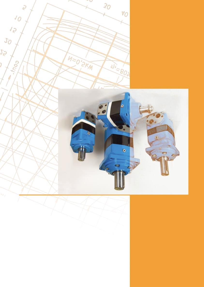
2 DISC VALVE HYDRAULIC DISC VALVE 's function is to distribute fluid to the Roller Gear Set. The pressure balanced sealing surface on the valve face and the separately driven maintains minimal leakage and mechanical losses. These gives the motors high efficiency- even at high pressures, and good starting characteristics. ROLLER GEAR SET minimizes friction and thereby increases efficiency while providing smooth output shaft rotation. MS, MT and MV are suitable for continuous operation under rough operating conditions- high pressures, thin oil, or frequent reversals. The Tapered roller bearings permit high radial loads. Standard Motor The standard motor mounting flange is located as close to the output shaft as possible. This type of mounting supports the motor close to the shaft load. This mounting flange is also compatible with many standard gear boxes. Wheel Motor The wheel motor mounting flange is located near the center of the motor which permits part or all of the motor to be located inside the wheel or roller hub. In traction drive applications, loads can be positioned over the motor bearings for best bearing life. This wheele motor mounting flange provides design flexibility in many applications. Short Motor This motor is assembled without the output shaft, bearings and bearing housing and has the same drive components as the standard and wheel motors. The short motor is especially suited for applications such as gear boxes, winch, reel and roll drives. Short motor applications must be designed with a bearing supported internal spline to mate with the bearing less motor drive. Product designs using these hydraulic motors provide considerable cost savings. Low Leakage LL Series hydraulic motors have been designed to operate at the whole standard range of working conditions (pressure drop and frequency of rotation ), but with considerable decreased volumetric losses in the drainage ports. Their main purpose is to operate as series-connected motors in hydraulic systems. For this version is permissible decreasing of the maximal torque with up to 5% (at middle speed) and up to 1 % (at high speed) in comparison to the standard versions of motors. This version is available for the EPMS motors. Low Speed Valve LSV Series hydraulic motors have been designed to operate with normal pressure drop and to ensure -1 smooth run at low speed (up to min ), as the best security for operation is guaranteed at frequency -1 of rotation 5 min. They have an increased starting pressure drop and are not recommended for using at pressure less than 4 bar. This version is available for the EPMS motors.
3 HYDRAULIC MS APPLICATION» Conveyors» Metal working machine» Machines for agriculture» Road building machines» Mining machinery» Food industries» Special vehicles etc. CONTENTS Specification data Function diagrams Dimensions and mounting Wheel motor... 1 Motor with Drum brake- MSB Shaft extensions Permissible shaft loads Function diagram for MSB Permissible Shaft Seal pressure...17 Tacho connection Dimensions and mounting- MSS, V, U... 1 Internal Spline data... Order code OPTIONS» Model- Disc valve, roll-gerotor» Flange and wheel mount» Short motor» Motor with Drum Brake» Tacho connection» Speed sensoring» Side and rear ports» Shafts- straight, splined and tapered» Metric and BSPP ports» Other special features GENERAL Displacement, [cm /rev.] Max. Speed, [RPM] Max. Torque, [danm] Max. Output, [kw] Max. Pressure Drop, [bar] Max. Oil Flow, [l/min] Min. Speed, [RPM] Permissible Shaft Loads, [dan] Pressure fluid O Temperature range, [C] 2 Optimal Viscosity range, [mm /s] Filtration, P =5 a Mineral based- HLP(DIN 51524) or HM(ISO 674/4) - 9 ISO code /16 (Min. recommended fluid filtration of 25 micron) Pressure drop (bar) 14 Oil flow in drain line Viscosity 2 (mm /s) 5 5 Oil flow in drain line (l/min) 1,5 1 2 Pressure Losses P bar Q, l/min 4
4 MS SPECIFICATION DATA Type MS MS 1 MS 125 MS 16 Displacement [cm /rev.] Max. Speed, [RPM] Max. Torque [danm] peak** Max. Output [kw] int.* Max. Pressure Drop [bar] peak** Max. Oil Flow [l/min] Max. Inlet Pressure [bar] peak** Max. Return Pressure with Drain Line [bar] peak** Max. Starting Pressure with Unloaded Shaft, [bar] Min. Starting Torque at max. press. drop [danm] at max. press. drop Min. Speed***, [RPM] Weight, [kg] MS(F) MSW For Rear Ports MSS(Z) +,4 kg MSV MSQ MSB, , ,5 19,4 1 9,9 1,4 7,9 5, 1, 16, , , ,9 26,4 1 1,1 1,6,1 6 1,5 17,1 125, , ,4 1,9,4 6, 1, 17,4 159, ,5 51,5 15,5 21, ,9 4,5 1, 11,, 6,7 11,2 17, * Intermittent operation: the permissible values may occur for max. 1% of every minute. ** Peak load: the permissible values may occur for max. 1% of every minute. *** For speeds of 5 RPM lower than given, consult factory or your regional manager. 1) Intermittent speed and intermittent pressure must not occur simultaneously. 2) Recommended filtration is per ISO cleanliness code /16. A nominal filtration of 25 micron or better. ) Recommend using a premium quality, anti-wear type mineral based hydraulic oil HLP(DIN51524) or HM (ISO 674/4). If using synthetic fluids consult the factory for alternative seal materials. 4) Recommended minimum oil viscosity 1 mm²/s at operating temperatures. 5) Recommended maximum system operating temperature is 2 C. 6) To assure optimum motor life fill with fluid prior to loading and run at moderate load and speed for 1-15 minutes. 5
5 MS MS SPECIFICATION DATA (continued) Type MS MS 25 MS 15 MS 4 Displacement [cm /rev.] Max. Speed, [RPM] Max. Torque [danm] peak** Max. Output [kw] int.* Max. Pressure Drop [bar] peak** Max. Oil Flow [l/min] Max. Inlet Pressure [bar] peak** Max. Return Pressure with Drain Line [bar] peak** Max. Starting Pressure with Unloaded Shaft, [bar] Min. Starting Torque at max. press. drop [danm] at max. press. drop Min. Speed***, [RPM] Weight, [kg] MS(F) MSW For Rear Ports MSS(Z) +,4 kg MSV MSQ MSB ,5 4,5 6 11,2 11,7 9,2 7,1 11,6 1, , ,7 12,2 9,7 7,6 12,1 1,7 14, ,5 1, ,4 12,9 1,4, 12, 19, , 1, 11, 9,2 1,7, * Intermittent operation: the permissible values may occur for max. 1% of every minute. ** Peak load: the permissible values may occur for max. 1% of every minute. *** For speeds of 5 RPM lower than given, consult factory or your regional manager. 1) Intermittent speed and intermittent pressure must not occur simultaneously. 2) Recommended filtration is per ISO cleanliness code /16. A nominal filtration of 25 micron or better. ) Recommend using a premium quality, anti-wear type mineral based hydraulic oil HLP(DIN51524) or HM (ISO 674/4). If using synthetic fluids consult the factory for alternative seal materials. 4) Recommended minimum oil viscosity 1 mm²/s at operating temperatures. 5) Recommended maximum system operating temperature is 2 C. 6) To assure optimum motor life fill with fluid prior to loading and run at moderate load and speed for 1-15 minutes. 6
6 MS FUNCTION DIAGRAMS MS M danm Q=5 l/min 1 l/min l/min l/min 4 l/min 5 l/min 65 l/min l/min int. 2kW 1 kw 4kW 6kW kw t =5% 12 kw 21 kw 15 kw 1 kw p=225 bar 5 bar 1 bar 14 bar 15 bar 1 bar 5 N=1 kw % 7 bar 7% int. 5 bar n -1 min (rpm) MS 1 M danm 5 Q=5 l/min l/min 1 l/min l/min 4 l/min 5 l/min 6 l/min l/min 9 l/min int. 2kW N=1 kw % t =5% 7% 1 kw 4kW 6kW kw 12 kw 24 kw 21 kw 15 kw 1 kw int. p=225 bar 5 bar 1 bar 14 bar 15 bar 1 bar 7 bar 5 bar n min (rpm) The function diagrams data was collected at back pressure 5 1 bar and oil with viscosity of 2 mm²/s at 5 C. 7
7 MS FUNCTION DIAGRAMS MS 125 M danm Q=5 l/min 1 l/min l/min l/min 4 l/min 5 l/min 6 l/min l/min 9 l/min int. 4kW 6kW 1 kw kw 12 kw 1 kw 15 kw 21 kw 24 kw p=225 bar 5 bar 1 bar 14 bar 15 2kW 15 bar 1 5 N=1 kw t =5% % 7% int bar 5 bar n -1 min (rpm) MS 16 M danm int. Q=5 l/min 1 l/min l/min 2kW N=1 kw % l/min 4 l/min 5 l/min 6 l/min 4kW 6kW kw t =5% 7% 1 kw l/min 15 kw 12 kw kw 9 l/min 1 kw int. 6 p=225 bar 5 bar 1 bar 15 bar 15 bar 7 bar 5 bar n -1 min (rpm) The function diagrams data was collected at back pressure 5 1 bar and oil with viscosity of 2 mm²/s at 5 C.
8 MS FUNCTION DIAGRAMS MS M danm Q=5 l/min 1 l/min l/min l/min 4 l/min 5 l/min 6 l/min l/min 9 l/min int. p= bar p=1 bar 1 kw p=16 bar 15 kw 14 bar 1 kw 12 kw 2kW 11 bar 4kW kw 6kW N=1 kw 7 bar t =5% % 5 bar 7% int. n min (rpm) MS 25 M danm Q=5 l/min 1 l/min l/min l/min 4 l/min 5 l/min 6 l/min l/min 9 l/min int. N=1 kw 2kW 4kW 6kW kw 12 kw 1 kw 15 kw p=1 bar p=155 bar p=14 bar 125 bar 95 bar 7 bar 1 5 t =7% 5% % 7% 5 bar int. n min (rpm) The function diagrams data was collected at back pressure 5 1 bar and oil with viscosity of 2 mm²/s at 5 C. 9
9 MS FUNCTION DIAGRAMS MS 15 M danm 7 Q=5 l/min 1 l/min l/min l/min 4 l/min 5 l/min 6 l/min l/min 9 l/min int. 2kW 4kW 6kW 1 kw kw 14 kw 12 kw p=14 bar 1 bar 1 bar bar N=1 kw 6 bar 45 bar t =5% % bar 7% int. n min (rpm) M danm int. MS 4 Q=5 l/min 1 l/min l/min l/min 4 l/min 5 l/min 6 l/min l/min 9 l/min N=1 kw 2kW t =5% 4kW % min (rpm) % 6kW 7% 1 kw kw 12 kw int. p=1 bar 1 bar 9 bar 7 bar 52,5 bar 5 bar 17,5 bar n The function diagrams data was collected at back pressure 5 1 bar and oil with viscosity of 2 mm²/s at 5 C. 1
10 MS DIMENSIONS AND MOUNTING DATA max L L 1 L 2 T Porting Side Ports Mounting SAE A-4 Mount (4 Holes) C 5 4xø1,5 Port A Port B P (A,B) ø16,4±,2 max N* 15 E Rear Ports 2±, Port A max L plugged A SAE A-2 Mount (2 Holes) 2xø1,5 P (A,B) 2±, Port B max N* *For N see page 15 C: 2xM1-12 mm depth P(A,B) : 2xG1/2 or 2xM22x1,5-15 mm depth T: G ¼ or M14x1,5-12 mm depth (plugged) Standard Rotation Viewed from Shaft End Port A Pressurized - CW Port B Pressurized - CCW Reverse Rotation Viewed from Shaft End Port A Pressurized - CCW Port B Pressurized - CW Type MS(A) MS(A) 1 MS(A) 125 MS(A) 16 MS(A) MS(A) 25 MS(A) 15 MS(A) 4 MSY(A) 4 L, mm L,mm 2 Type L, mm L,mm MS(A)E MS(A)E 1 MS(A)E 125 MS(A)E 16 MS(A)E MS(A)E 25 MS(A)E 15 MS(A)E 4 MSY(A)E ,4 21, 27, 4, 4,5 54, 69,4 2,6 1 11
11 max MS DIMENSIONS AND MOUNTING DATA max L L 1 L 2 T Porting Side Ports C 5 Mounting F Magneto Mount (4 Holes) 4xø1,5 Port A Port B P (A,B) max N* ø16,4±,2 E Rear Ports Q Square Mount (4 Holes) max L 2±, Port A plugged 5 5±,4 4xø11,5 12 P (A,B) 2±, Port B 12 ø16,4±,2 max N 1 * *For N and N 1 see page 15 C: 2xM1-12 mm depth P(A,B) : 2xG1/2 or 2xM22x1,5-15 mm depth T: G ¼ or M14x1,5-12 mm depth (plugged) Standard Rotation Viewed from Shaft End Port A Pressurized - CW Port B Pressurized - CCW Reverse Rotation Viewed from Shaft End Port A Pressurized - CCW Port B Pressurized - CW Type MSF MSF 1 MSF 125 MSF 16 MSF MSF 25 MSF 15 MSF 4 MSYF 4 L, mm L,mm Type MSQ MSQ 1 MSQ 125 MSQ 16 MSQ MSQ 25 MSQ 15 MSQ 4 MSYQ 4 L, mm L,mm 2 Type L, mm Type L, mm L,mm MSFE MSFE 1 MSFE 125 MSFE 16 MSFE MSFE 25 MSFE 15 MSFE 4 MSYFE MSQE MSQE 1 MSQE 125 MSQE 16 MSQE MSQE 25 MSQE 15 MSQE 4 MSYQE ,4 21, 27, 4, 4,5 54, 69,4 2,6 1 12
12 MS DIMENSIONS AND MOUNTING DATA -MSW W Wheel Mount max N 2 T max L L 2 L 1 9 C P (A,B) 5 Port A Port B C: 2xM1-12 mm depth P (A,B): 2xG1/2 or 2xM22x1,5-15 mm depth T: G ¼ or M14x1,5-12 mm depth(plugged) E Rear Port *For N 2 see page 15 Port A Port B Standard Rotation Viewed from Shaft End Port A Pressurized - CW Port B Pressurized - CCW plugged Reverse Rotation Viewed from Shaft End Port A Pressurized - CCW Port B Pressurized - CW Type MSW MSW1 MSW 125 MSW 16 MSW MSW 25 MSW 15 MSW 4 MSYW 4 L, mm L,mm 1 L,mm , , 95 27, 11 4, 1 4, , 12 69,4 14 2, Type MSWE MSWE 1 MSWE 125 MSWE 16 MSWE MSWE 25 MSWE 15 MSWE 4 MSYWE 4 L, mm
13 MS DIMENSIONS AND MOUNTING DATA -MSB A B Actuating the brake level, the brake shaft is turned. The rectangular shape of the inner part of this shaft forces the brake pads to be pressed against the brake drum. This brakes the wheel or the winch drum. Releasing the level, the springs pull it and the brake pads back to the initial position. The motor output shaft is released. Minimum angle adjustment is 1. It can be adjusted by dismounting the level. Depending on the application You can choose the actuating direction of the brake level. The rod connection actuating the brake should be capable of moving at last 25 mm from neutral to extreme position. B Motor with Drum Brake M D MSBL MSBR P L P L T Port A Port B P (A,B) C E Rear Port C: 2xM1-12 mm depth F: Inspection hole for checking brake lining T: G 1/4 or M14x1,5-12 mm depth (plugged) P : 2xG1/2 or 2xM22x1,5-15 mm depth (A,B) P (A,B) Port A Port B Standard Rotation Viewed from Shaft End Port A Pressurized - CW Port B Pressurized - CCW Reverse Rotation Viewed from Shaft End Port A Pressurized - CCW Port B Pressurized - CW plugged Type MSB MSB1 MSB 125 MSB 16 MSB MSB 25 MSB 15 MSB 4 L, mm L,mm ,4 21, 27, 4, 4,5 54, 69,4 L,mm Type MSBE MSBE 1 MSBE 125 MSBE 16 MSBE MSBE 25 MSBE 15 MSBE 4 L, mm
14 MS SHAFT EXTENSIONS C - ø2 straight, Parallel key A1xx45 DIN 65 Max. Torque 77 danm K - tapered 1:1, Parallel key B6x6x DIN 65 Max. Torque 95 danm S=41 Tightening torque ±1 danm ø5 -,9 ø4,5±,1 56,5±,4 N=67,5 N =54,5; N = ±,4 N=67,5 N =54,5; N = , CO- ø1¼" straight, Parallel key 16 "x 16 "x 1¼"BS46 Max. Torque 77 danm SH - ø1¼" splined 14T, DP12/24 ANSI B Max. Torque 95 danm 6 +2 ø5 ø1, -,25 ±,4 N=57,5 N =44,5; N = M min 16 Deep 56,5±,4 N=67,5 N =54,5; N = SL - ø4,5 p.t.o. DIN 9611 Form 1 Max. Torque 77 danm 1±,4 76±1 ±,25 - Motor Mounting Surface N - for standart,a and F flange N1 - for Q flange N - for W flange 2 N=11 N =96,5; N =
15 MS PERMISSIBLE SHAFT LOADS The output shaft runs in tapered bearings that permit high axial and radial forces. Curve "1" shows max. radial shaft load. Any shaft load exceeding the values quoted in the curve will seriously reduce motor life. The two other curves apply to a B1 bearing life of hours at RPM. P max=5dan a max 67,15 Prad dan 25 1 P =dan a P max=5dan a max P max=5dan a mm P max=5dan a PL [dan] 14 1 FUNCTION DIAGRAM MSB M B PL - Brake Lever Load MB - Brake Torque M - Brake Lever Torque D M D M [danm] D M [danm] B
16 MS MAX. PERMISSIBLE SHAFT SEAL PRESSURE P bar : Drawing for Standard Shaft Seal 2: Drawing for High Pressure Seal (" U" Seal) n, min -1 WITH TACHO CONNECTION 72 17
17 -,4 -,12 MS DIMENSIONS AND MOUNTING DATA - MSS, MSV and MSU max L L 2 L 1 T Porting Mounting Side Ports ø125±,15 S Short Mount min 2, max 27,1 C 4xø11 Port A Port B P (A,B) ø5 16 "O" Ring 1x 6±,2 max ø145 2 E Rear Ports max L V Very Short Mount max L max 25 2±, Port A plugged 4xM1 7 ø14±,15 L 1 P (A,B) 2±, Port B ø5 Drain port 5 1 "O" Ring 5x2 16±,1 min 45, max 45,6 C: 2xM1-12 mm depth P(A,B) : 2xG1/2 or 2xM22x1,5-15 mm depth T: G ¼ or M14x1,5-12 mm depth (plugged) 4xM1 25,7 U Ultra Short Mount max L L 2 L 1 min 44,1 max 46,1 Standard Rotation Viewed from Shaft End Port A Pressurized - CW Port B Pressurized - CCW Reverse Rotation Viewed from Shaft End Port A Pressurized - CCW Port B Pressurized - CW ø5 Drain port 5 ø14±,15 7 ø -,4 "O" Ring x max 2 Type MSS MSS 1 MSS 125 MSS 16 MSS MSS 25 MSS 15 MSS 4 MSYS 4 L, mm L,mm 2 Type L, mm Type L, mm L,mm 2 Type L, mm 125 MSSE 14 MSV MSVE MSSE 1 MSSE 125 MSSE 16 MSSE MSSE 25 MSSE 15 MSSE 4 MSYSE MSV 1 MSV 125 MSV 16 MSV MSV 25 MSV 15 MSV 4 MSYV , , MSVE 1 MSVE 125 MSVE 16 MSVE MSVE 25 MSVE 15 MSVE 4 MSYVE Type MSU MSU 1 MSU 125 MSU 16 MSU MSU 25 MSU 15 MSU 4 L, mm 15, L,mm Type L,mm 2 L, mm 1 6 MSUE 111, , , ,5 MSUE 1 MSUE 125 MSUE 16 MSUE MSUE 25 MSUE 15 MSUE ,4 21, 27, 4, 4,5 54, 69,4 2,6 1
18 MS DIMENSIONS OF THE ATTACHED COMPONENT For MSS I T F H J F: Oil circulation hole H: Hardened stop plate I: O- Ring 1xmm J: 4xM1-16 mm depth, 9 T: Drain connection G1/4 or M14x1,5 For MSV E H E: External drain hole H: Hardened stop plate I: O- Ring 5x2mm 19
19 MS DIMENSIONS OF THE ATTACHED COMPONENT(continued) For MSU ø J I J: I: 4xM1-26 mm depth, 9, ø14 O- Ring x mm DRAIN CONNECTION A drain line ought to be used when pressure in the return line can exceed the permissible pressure. It can be connected: - For MSS at the drain port of the motor; - For MSV and MSU at the drain connection of the attached component. The maximum pressure in the drain line is limited by the attached component and its shaft seal. The drain line must be possible for oil to flow freely between motor and attached component and must be led to the tank. The maximum pressure in the drain line is limited by the attached component and its seal. INTERNAL SPLINE DATA FOR THE ATTACHED COMPONENT Standard ANS B , class 5 [ m=2.1166; corrected x.m=+,] Fillet Root Side Fit mm Number of Teeth z 12 Diametral Pitch DP 12/24 Pressure Angle O Pitch Dia. D 25,4 Major Dia. Dri 2, -,1 Minor Dia. Di 2, +, Space Width [Circular] Lo 4,±, Fillet Radius Rmin,2 Max. Measurement between Pin L 17,62 +,15 Pin Dia. d 4,5±,1 Above are when hardened Hardering Specification: HRC 6±2 Effective case depth ( HRC 52),7±,2 mm Materiall MoCr4 DIN 17 or better
20 MS ORDER CODE MS Pos.1 - Mounting Flange omit - SAE A-4 mount, four holes A F Q B S V U W Pos.2 - Port type omit - Side ports E - Rear ports Pos. - Displacement code -,5 [cm /rev] 1-1, [cm /rev] ,7 [cm /rev] ,7 [cm /rev] -, [cm /rev] 25-25, [cm /rev] 15-14,9 [cm /rev] 4-97, [cm /rev] Pos.4 - Shaft Extensions* C - ø2 straight, Parallel key A1xx45 DIN CO - ø1¼" straight, Parallel key / x / x1¼ BS46 K SL SH - SAE A-2 mount, two holes - Magneto mount, four holes - Square mount, four holes - Motor with drum brake - Short mount - Very short mount - Ultra short mount - Wheel mount ø5 tapered 1:1, Parallel key B6x6x DIN65 - ø4,5 p.t.o. DIN 9611 Form 1 - ø1¼" splined 14T ANSI B Pos. 5 - Shaft Seal Version (see page 17) omit U Pos. 6 - Ports omit - BSPP (ISO 22) M - Metric (ISO 262) Pos. 7 - Actuating Direction** /R /L - Low pressure seal - High pressure seal - Right - Left Pos. - Special Features (see page 5) Pos. 9 - Design Series omit - Factory specified NOTES: * The permissible output torque for shafts must not be exceeded! ** Only for MSB The hydraulic motors are mangano-phosphatized as standard. 21
21 HYDRAULIC MSY MSY is the new hydraulic motor in a family of "disc valve" series which has dimensions and mounting data the same as at hydraulic motors type MS. This motor is described with 15 % higher technical data-max. Torque and max. Pressure drop, thereby higher power. This makes it suitable for vehicles with greater loads and speed drop. CONTENTS Specification data... 2 Function diagrams Dimensions and mounting Wheel motor... 1 Shaft extensions Permissible shaft loads Permissible Shaft Seal Pressure...17 Dimensions and mounting- MSYS, V Internal Spline data... 2 Order code... 2 OPTIONS» Model- Disc valve, roll-gerotor» Flange and wheel mount» Short motor» Side and rear ports» Shafts- straight, splined and tapered» Other special features GENERAL Displacement, [cm /rev.] Max. Speed, [RPM] Max. Torque, [danm] Max. Output, [kw] Max. Pressure Drop, [bar] Max. Oil Flow, [l/min] Min. Speed, [RPM] Permissible Shaft Loads, [dan] Pressure fluid O Temperature range, [C] 2 Optimal Viscosity range, [mm /s] Filtration 474, , , P =5 a Mineral based- HLP(DIN 51524) or HM(ISO 674/4) - 9 ISO code /16 (Min. recommended fluid filtration of 25 micron) Pressure drop (bar) 14 Oil flow in drain line Viscosity 2 (mm /s) 5 5 Oil flow in drain line (l/min) 1,5 1 2 P Pressure Losses bar Q, l/min 22
22 MSY EPMS SPECIFICATION DATA FOR MSY Type MSY MSY 25 MSY 15 MSY 4 MSY 4 Displacement [cm /rev.] Max. Speed, [RPM] Max. Torque [danm] peak** Max. Output [kw] int.* Max. Pressure Drop [bar] peak** Max. Oil Flow [l/min] Max. Inlet Pressure [bar] peak** Max. Return Pressure with Drain Line [bar] peak** Max. Starting Pressure with Unloaded Shaft, [bar] Min. Starting Torque at max. press. drop [danm] at max. press. drop Min. Speed***, [RPM] Weight, [kg] MSY (F) For Rear Ports MSYW +,4 kg MSYQ 45 56,6 64,5 65 1,1 24, ,2 5,7 6 11,2 11,7 11, ,,6,6 1, 2, , 6,6 6 11,7 12,2 12,1 14, , 96, 1 17, , 79,2 5 12,4 12,9 12, , 97, 11 11, , 7,7 5 1, 1, 1,7 474, , 11, ,4 15, 14,9 * Intermittent operation: the permissible values may occur for max. 1% of every minute. ** Peak load: the permissible values may occur for max. 1% of every minute. *** For speeds of 5 RPM lower than given, consult factory or your regional manager. 1) Intermittent speed and intermittent pressure must not occur simultaneously. 2) Recommended filtration is per ISO cleanliness code /16. A nominal filtration of 25 micron or better. ) Recommend using a premium quality, anti-wear type mineral based hydraulic oil HLP(DIN51524) or HM (ISO 674/4). If using synthetic fluids consult the factory for alternative seal materials. 4) Recommended minimum oil viscosity 1 mm²/s at operating temperatures. 5) Recommended maximum system operating temperature is 2 C. 6) To assure optimum motor life fill with fluid prior to loading and run at moderate load and speed for 1-15 minutes. 2
23 MSY MSY FUNCTION DIAGRAMS M danm 7 Q=5 l/min 1 l/min l/min l/min 4 l/min 5 l/min 6 l/min l/min 9 l/min int. 1 kw 21 kw 12 kw 15 kw 4kW kw 1 kw 6kW 2kW N=1 kw t =5% % 7% int p=225 bar bar 1 bar 14 bar 11 bar 7 bar 5 bar n -1 min (rpm) MSY 25 M danm 5 Q=5 l/min 1 l/min l/min l/min 4 l/min 5 l/min 6 l/min l/min 9 l/min int. 15 kw 21 kw 1 kw p=225 bar bar kw 155 bar 4 5 4kW 6kW kw 1 kw 125 bar 95 bar N=1 kw 2kW 5% 7 bar 1 5 t =7% % The function diagrams data was collected at back pressure 5 1 bar and oil with viscosity of 2 mm²/s at 5 C. 7% 24 int. 5 bar n -1 min (rpm)
24 MSY FUNCTION DIAGRAMS MSY 15 Q=5 l/min M danm 1 l/min l/min l/min 4 l/min 5 l/min 6 l/min l/min 9 l/min int. 14 kw 16 kw p=2 bar bar 1 bar kw kw 14 bar kW kw 1 bar 4 1 bar 5 2kW 4kW bar N=1 kw t =5% % 7% int MSY 4 6 bar 45 bar 5 bar n -1 min (rpm) Q=5 l/min M danm 1 l/min l/min 4 l/min 15 l/min l/min 5 l/min 6 l/min 7 l/min 9 l/min int. 1 kw 14 kw 12 kw p=1 bar 16 bar 14 bar bar 5 kw 1 bar kW 6kW 9 bar 5 7 bar kW N=1 kw t =5% % % 7% 52,5 bar 5 bar The function diagrams data was collected at back pressure 5 1 bar and oil with viscosity of 2 mm²/s at 5 C. 25 int. 17,5 bar n -1 min (rpm)
25 MSY FUNCTION DIAGRAMS MSY 4 M danm 11 Q=5 l/min 15 l/min l/min 4 l/min 5 l/min 1 l/min l/min 6 l/min l/min 9 l/min int. 1 kw 11 kw p=14 bar 1 bar 115 bar 6 5 kw 5kW 7kW 9kW 1 bar 5 bar 4 N=1 kw 2kW 7 bar 1 7% t =5% % % 6% int ,5 bar 5 bar 17,5 bar n -1 min (rpm) The function diagrams data was collected at back pressure 5 1 bar and oil with viscosity of 2 mm²/s at 5 C. 26
26 MSY The dimensions, mounting data, shaft extensions and permissible shaft loads are the same as at hydraulic motors type MS except following below. DIMENSIONS OF THE ATTACHED COMPONENT For MSYS I T F: Oil circulation hole H: Hardened stop plate I: O- Ring 1xmm J: 4xM1-16 mm depth, 9 T: Drain connection G1/4 or M14x1,5 E H For MSYV ø5,5 +,2 ø9 +,5 ø5,5 +,2 ø9 +,5 F H J E: External drain hole H: Hardened stop plate I: O- Ring 5x2mm DRAIN CONNECTION A drain line ought to be used when pressure in the return line can exceed the permissible pressure. It can be connected: - For MSYS at the drain port of the motor; - For MSYV at the drain connection of the attached component. The maximum pressure in the drain line is limited by the attached component and its shaft seal. The drain line must be possible for oil to flow freely between motor and attached component and must be led to the tank. The maximum pressure in the drain line is limited by the attached component and its seal. 27
27 MSY INTERNAL SPLINE DATA FOR THE ATTACHED COMPONENT Standard 12 DP 1/ ANSI B , class 5 [ m=2.54; corrected x.m=+,4] Fillet Root Side Fit mm Number of Teeth z 12 Diametral Pitch DP 1/ Pressure Angle O Pitch Dia. D,4 Major Dia. Dri,2 +,4 Minor Dia. Di 27, +,1 Space Width [Circular] Lo 4,45 +,71 Fillet Radius Rmin,2 Max. Measurement between Pin L 22,72 +,17 Pin Dia. d 5±,1 Above are when hardened Hardering Specification: HRC 6±2 Effective case depth (HRC 52),7±,2 mm Material: MoCr4 DIN 17 or better ORDER CODE MSY Pos.1 - Mounting Flange omit - SAE A mount, four holes A F Q S V W - SAE A mount, two holes - Magneto mount, four holes - Square mount, four holes - Short mount - Very short mount - Wheel mount Pos.2 - Port type omit - Side ports E - Rear ports Pos. - Displacement code -, [cm /rev] 25-25, [cm /rev] 15-14,9 [cm /rev] 4-97, [cm /rev] 4-474,5 [cm /rev] Pos. 4 - Shaft Extensions* C K SL SH - ø2 straight, Parallel key A1xx45 DIN65 - ø5 tapered 1:1, Parallel key B6x6x DIN65 - ø4,5 p.t.o. DIN 9611 Form 1 - ø1¼" splined 14T ANSI B Pos. 5 - Shaft Seal Version (see page 17) omit U Pos. 6 - Ports omit - BSPP (ISO 22) M - Metric (ISO 262) Pos. - Design Series omit - Low pressure seal - High pressure seal Pos. 7 - Special Features (see page 5) - Factory specified NOTES: * The permissible output torque for shafts must not be exceeded! The hydraulic motors are mangano-phosphatized as standard. 2
28 HYDRAULIC MT APPLICATION»»»»»» Conveyors Metal working machines Machines for agriculture Road building machines Mining machinery Food industries» Special vehicles» Plastic and rubber machinery etc. CONTENTS Specification data... Function diagrams... 1 Dimensions and mounting... 4 Shaft extensions... 5 Dimensions and mounting- MTS, V Internal Spline data... Permissible shaft loads... Tacho connection... 9 Order code... 9 OPTIONS» Model- Disc valve, roll-gerotor» Flange with wheel mount» Short motor» Tacho connection» Speed sensoring» Side and rear ports» Shafts- straight, splined and tapered» Metric and BSPP ports» Other special features GENERAL Displacement, [cm /rev.] Max. Speed, [RPM] Max. Torque, [danm] Max. Output, [kw] Max. Pressure Drop, [bar] Max. Oil Flow, [l/min] Min. Speed, [RPM] Permissible Shaft Loads, [dan] Pressure fluid O Temperature range, [C] 2 Optimal Viscosity range, [mm /s] Filtration 161,1 52, ,5, P =1 a Mineral based- HLP(DIN 51524) or HM(ISO 674/4) - 9 ISO code /16 (Min. recommended fluid filtration of 25 micron) Pressure drop (bar) 14 Oil flow in drain line Viscosity 2 (mm /s) 5 5 Oil flow in drain line (l/min) 2,5 1,5 5 Pressure Losses P bar Q, l/min 29
29 MT SPECIFICATION DATA Type MT 16 MT MT 25 MT 15 MT 4 MT 5 Displacement [cm /rev.] Max. Speed, [RPM] Max. Torque [danm] peak** Max. Output [kw] Max. Pressure Drop [bar] int.* peak** Max. Oil Flow [l/min] Max. Inlet Pressure [bar] Max. Return Pressure peak** -1 RPM without Drain Line or 1- RPM Max. Pressure > RPM in Drain Line, [bar] -max. RPM Max. Return Pressure with Drain Line [bar] peak** Max. Starting Pressure with Unloaded Shaft, [bar] Min. Starting Torque [danm] at max. press. drop at max. press. drop Min. Speed***, [RPM] Weight, [kg] MT MTW MTS MTV 161, , , , ,5 22,5 15,5 11,5 251, , , , , , , * Intermittent operation: the permissible values may occur for max. 1% of every minute. ** Peak load: the permissible values may occur for max. 1% of every minute. *** For speeds of 5 RPM lower than given, consult factory or your regional manager. 1) Intermittent speed and intermittent pressure must not occur simultaneously. 2) Recommended filtration is per ISO cleanliness code /16. A nominal filtration of 25 micron or better. ) Recommend using a premium quality, anti-wear type mineral based hydraulic oil, HLP(DIN51524) or HM(ISO674/4). If using synthetic fluids consult the factory for alternative seal materials. 4) Recommended minimum oil viscosity 1 mm²/s at 5ºC. 5) Recommended maximum system operating temperature is 2ºC. 6) To assure optimum motor life fill with fluid prior to loading and run at moderate load and speed for 1-15 minutes.
30 MT FUNCTION DIAGRAMS MT 16 Cont. Cont. MT Cont. Cont. The function diagrams data was collected at back pressure 5 1 bar and oil with viscosity of 2 mm²/s at 5 C. 1
31 MT FUNCTION DIAGRAMS MT 25 Cont. MT 15 Cont. Cont. Cont. 2
32 MT MT 4 FUNCTION DIAGRAMS Cont. Cont. MT 5 Cont. Cont. The function diagrams data was collected at back pressure 5 1 bar and oil with viscosity of 2 mm²/s at 5 C.
33 MT DIMENSIONS AND MOUNTING DATA Port A Port B C Porting Side Ports Mounting Square Mount (4 Holes) T P (A,B) E Rear Ports W Wheel Mount P (A,B) Port A Port B Standard Rotation Viewed from Shaft End Port A Pressurized - CW Port B Pressurized - CCW Reverse Rotation Viewed from Shaft End Port A Pressurized - CCW Port B Pressurized - CW T C: 4xM1-1 mm depth P (A,B): 2xG/4 or 2xM27x2-17 mm depth T: G 1/4 or M14x1,5-12 mm depth (plugged) Type MT 16 MT MT 25 MT 15 MT 4 MT 5 L, mm Type MTE 16 MTE MTE 25 MTE 15 MTE 4 MTE 5 L,mm E L,mm 2 Type L, mm Type L,mm L,mm 2 L,mm MTW 16 MTW MTW 25 MTW 15 MTW 4 MTW MTWE 16 MTWE MTWE 25 MTWE 15 MTWE 4 MTWE , 4, E 4
34 MT SHAFT EXTENSIONS C -ø4 straight, Parallel key A12xx7 DIN 65 Max. Torque 12, danm K -tapered 1:1, Parallel key B12xx2 DIN 65 Max. Torque,7 danm S=46 Tightening Torque 5± danm ,2 max 114 (11 for W-flange) max 114 (11 for W-flange) -ø1½" straight, Parallel key "x CO "x 2¼" BS46 Max. Torque 12, danm SH -ø1½" splined 17T, DP 12/24 ANSI B Max. Torque 12, danm ,2 max 114 (11 for W-flange) 2 -,2 max 114 (11 for W-flange) SL -ø4,5 p.t.o. DIN 9611 Form 1 Max. Torque 77 danm 12 -, Motor Mounting Surface max 14 (2 for W-flange) 5
35 MT DIMENSIONS AND MOUNTING DATA - MTS and MTV Port A Port B Porting Side Ports Mounting S - Short Mount C P (A,B) T P (A,B) Port A E Rear Ports V - Very Short Mount Port B Standard Rotation Viewed from Shaft End Port A Pressurized - CW Port B Pressurized - CCW Reverse Rotation Viewed from Shaft End Port A Pressurized - CCW Port B Pressurized - CW C: 4xM1-1 mm depth P (A,B): 2xG/4 or 2xM27x2-17 mm depth T: G 1/4 or M14x1,5-12 mm depth (plugged) Type MTS 16 MTS MTS 25 MTS 15 MTS 4 MTS 5 L, mm Type MTSE 16 MTSE MTSE 25 MTSE 15 MTSE 4 MTSE 5 L, mm L,mm Type MTV 16 MTV MTV 25 MTV 15 MTV 4 MTV 5 L, mm Type MTVE 16 MTVE MTVE 25 MTVE 15 MTVE 4 MTVE 5 L, mm L,mm 2 5,5 6,5 7, 79 9,5 1,5 L,mm , 4,
36 MT DIMENSIONS OF THE ATTACHED COMPONENT MTS I T G F H J F: Oil circulation hole G: Internal drain channel H: Hardened stop plate I: O- Ring 125xmm J: 4xM12-1 mm depth, 9 T: Drain connection G1/4 or M14x1,5 MTV J I F H F: Oil circulation hole J: 4xM14-26 mm depth, 9 H: Hardened stop plate I: O- Ring 1xmm DRAIN CONNECTION A drain line ought to be used when pressure in the return line can exceed the permissible pressure. It can be connected: - For MTS at the drain port of the motor; - For MTV at the drain connection of the attached component. The maximum pressure in the drain line is limited by the attached component and its shaft seal. The drain line must be possible for oil to flow freely between motor and attached component and must be led to the tank. The maximum pressure in the drain line is limited by the attached component and its seal. 7
37 MT INTERNAL SPLINE DATA FOR THE ATTACHED COMPONENT Standard ANSI B , class 5 [m=2.1166; corrected x.m=+1,] Fillet Root Side Fit mm Number of Teeth z 16 Diametral Pitch DP 12/24 Pressure Angle O Pitch Dia. D,656 Major Dia. Dri,4 +,4 Minor Dia. Di 2,15 +,4 Space Width [Circular] Lo 4,516±,7 Fillet Radius Rmin,5 Max. Measurement between Pin L 26,9 +,1 Pin Dia. d 4,5±,1 L Hardening Specification: HRC 6±2 HRC 52,7±,2 mm effective case depth Material MoCr4 DIN 17 or better PERMISSIBLE SHAFT LOADS The output shaft runs in tapered bearings that permit high axial and radial forces. Curve " 1" shows max. radial shaft load. Any shaft load exceeding the values quoted in the curve will seriously reduce motor life. The two other curves apply to a B1 bearing life of hours at RPM. P rad (dan) 4 1 Pa= Pa=1 dan (mm) max 114 Pa =1 dan max max 11 Pa =1 dan max
38 MT WITH TACHO CONNECTION ORDER CODE MT Pos.1 - Mounting Flange omit S V W - Square mount, four holes - Short mount - Very short mount - Wheel mount Pos.2 - Port type omit - Side ports E - Rear ports Pos. - Displacement code ,1[cm /rev] - 1,4[cm /rev] ,[cm /rev] 15-26,[cm /rev] 4-41,9[cm /rev] 5-52,6[cm /rev] Pos.4 - Shaft Extensions* C - ø4 straight, Parallel key A12xx7 DIN65 CO - ø1½ straight, Parallel key / x / x2¼ BS46 K - ø45 tapered 1:1, Parallel key B12xx2 DIN65 SL - ø4,5 p.t.o. DIN 9611 Form 1 SH - ø1½" splined 17T ANSI B Pos. 5 - Ports omit - BSPP (ISO 22) M - Metric (ISO 262) Pos. 6 - Special Features (see page 5) Pos. 7 - Design Series omit - Factory specified NOTES: * The permissible output torque for shafts must not be exceeded! The hydraulic motors are mangano-phosphatized as standard. 9
39 HYDRAULIC MV APPLICATION»»»»»» Conveyors Metal working machines Machines for agriculture Road building machines Mining machinery Food industries» Special vehicles» Plastic and rubber machinery etc. CONTENTS Specification data Function diagrams Permissible shaft loads Dimensions and mounting Dimensions and mounting- MVS Dimensions and mounting- MVV Internal Spline data... 4 Tacho connection... 4 Shaft extensions Order code OPTIONS» Model- Disc valve, roll-gerotor» Flange and wheel mount» Short motor» Tacho connection» Speed sensoring» Side ports» Shafts- straight, splined and tapered» Metric and BSPP ports» Other special features GENERAL Displacement, [cm /rev.] Max. Speed, [RPM] Max. Torque, [danm] Max. Output, [kw] Max. Pressure Drop, [bar] Max. Oil Flow, [l/min] Min. Speed, [RPM] Permissible Shaft Loads, [dan] Pressure fluid O Temperature range, [C] 2 Optimal Viscosity range, [mm /s] Filtration 14,5 1, ,5 5, P =15 a Mineral based- HLP(DIN 51524) or HM(ISO 674/4) - 9 ISO code /16 (Min. recommended fluid filtration of 25 micron) Oil flow in drain line Pressure Losses bar 16 Pressure drop (bar) 14 Viscosity 2 (mm /s) 5 5 Oil flow in drain line (l/min) Q l/min 4
40 MV SPECIFICATION DATA Type MV 15 MV 4 MV 5 MV 6 MV Displacement [cm /rev.] Max. Speed, [RPM] Max. Torque [danm] peak** Max. Output [kw] Max. Pressure Drop [bar] int.* peak** Max. Oil Flow [l/min] Max. Inlet Pressure [bar] Max. Return Pressure peak** -1 RPM without Drain Line or 1- RPM Max. Pressure > RPM indrainline,[bar] -max. RPM Max. Return Pressure with Drain Line [bar] peak** Max. Starting Pressure with Unloaded Shaft, [bar] Min. Starting Torque [danm] at max. press. drop at max. press. drop Min. Speed***, [RPM] Weight, avg. [kg] MV MVW MVS , , 2,4 22,7 4, , ,6,2 2,5 499, , ,5 4,1 24,4 629, ,9 5,5 25,6 1, , ,5 7,1 27,7 * Intermittent operation: the permissible values may occur for max. 1% of every minute. ** Peak load: the permissible values may occur for max. 1% of every minute. *** For speeds of 5 RPM lower than given, consult factory or your regional manager. 1) Intermittent speed and intermittent pressure must not occur simultaneously. 2) Recommended filtration is per ISO cleanliness code /16. A nominal filtration of 25 micron or better. ) Recommend using a premium quality, anti-wear type mineral based hydraulic oil, HLP(DIN51524) or HM(ISO674/4). If using synthetic fluids consult the factory for alternative seal materials. 4) Recommended minimum oil viscosity 1 mm²/s at 5ºC. 5) Recommended maximum system operating temperature is 2ºC. 6) To assure optimum motor life fill with fluid prior to loading and run at moderate load and speed for 1-15 minutes. 41
41 MV FUNCTION DIAGRAMS MV 15 M danm 1 Q=1 l/min 25 l/min 5 l/min l/min 1 l/min 125 l/min 15 l/min 16 l/min l/min 1 int. kw kw 4 kw 5 kw p=24 bar bar 1 bar 6 1 kw 14 bar 4 N=5 kw % % 7% int. 15 bar 7 bar 5 bar n -1 min (rpm) MV 4 M danm 16 Q=1 l/min 25 l/min 5 l/min l/min 1 l/min 125 l/min 15 l/min 1 l/min l/min 24 l/min 14 p=24 bar 1 int % N=5 kw % 1 kw 7% 5% kw 5 kw 4 kw kw int. bar 1 bar 14 bar 15 bar 7 bar 5 bar n min (rpm) The function diagrams data was collected at back pressure 5 1 bar and oil with viscosity of 2 mm²/s at 5 C. 42
42 MV FUNCTION DIAGRAMS MV 5 M danm Q=1 l/min 25 l/min 5 l/min 1 l/min l/min 1 l/min 125 l/min 15 l/min l/min 24 l/min int. kw 4 kw 5 kw 6 kw p=24 bar bar kw kw 1 bar 14 bar 6 N=5 kw 15 bar 4 7% 5% 7 bar % 7% 5 bar int. n min (rpm) MV 6 M danm Q=1 l/min 25 l/min 5 l/min 1 l/min l/min 1 l/min 125 l/min 15 l/min l/min 24 l/min int. kw kw 4 kw 5 kw 6 kw p= bar 1 bar 15 bar 1 1 bar N=5 kw 1 kw 9 bar % 5% % 7% 6 bar bar int. n -1 min (rpm) The function diagrams data was collected at back pressure 5 1 bar and oil with viscosity of 2 mm²/s at 5 C. 4
43 MV M danm 225 MV Q=1 l/min 25 l/min 5 l/min FUNCTION DIAGRAMS 1 l/min l/min 1 l/min 125 l/min 15 l/min l/min 24 l/min int. kw kw 4 kw p=1 bar 16 bar 1 bar 1 1 kw 1 bar 5 25 N=5 kw 5% % 7% The function diagrams data was collected at back pressure 5 1 bar and oil with viscosity of 2 mm²/s at 5 C. int. bar 5 bar 25 bar n -1 min (rpm) Prad dan 6 1 PERMISSIBLE SHAFT LOADS P = dan a mm P =15 dan a The output shaft runs in tapered bearings that permit high axial and radial forces. Curve " 1" shows max. radial shaft load. Any shaft load exceeding the values quoted in the curve will seriously reduce motor life. The two other curves apply to a B1 bearing life of hours at RPM. P =15 dan a P =15 dan a 44
44 MV DIMENSIONS AND MOUNTING DATA Port A Port B Mounting Square Mount (4 Holes) T Porting Side Ports P (A, B) C C SAE C Mount T C: 4xM12-12 mm depth P (A,B): 2xG1 - mm depth T: G 1/4-12 mm depth W Wheel Mount Standard Rotation Viewed from Shaft End Port A Pressurized - CW Port B Pressurized - CCW Reverse Rotation Viewed from Shaft End Port A Pressurized - CCW Port B Pressurized - CW T Type MV 15 MV 4 MV 5 MV 6 MV L, mm 214,5 221,5 229,5 24, 254, L,mm 2 Type L, mm L,mm 2 Type L, mm L,mm 2 *L, mm MVC 15 MVC 4 MVC 5 MVC 6 MVC 2,25 245,25 25,25 26, 277, 14,26 191,26 199,26 9,76 22,76 MVW 15 MVW 4 MVW 5 MVW 6 MVW ,5 2,5 6,5 47, 61, 1 * The width of the gerolor is 4 mm greater than L. 1 45
45 MV DIMENSIONS AND MOUNTING S Short Mount Port A Port B T 69 C P(A,B) 4xø14 Type MVS 15 MVS 4 MVS 5 MVS 6 MVS L, mm *L, mm 1 22, 29, 7, 47,5 61,5 L,mm C: 4xM12-12 mm depth P (A,B): 2xG1 - mm depth T: G 1/4-12 mm depth * The width of the gerolor is 4 mm greater than L 1. Standard Rotation Reverse Rotation Viewed from Shaft End Viewed from Shaft End Port A Pressurized - CW Port A Pressurized - CCW Port B Pressurized - CCW Port B Pressurized - CW DIMENSIONS OF THE ATTACHED COMPONENT MVS ø1±,2 F: Oil circulation hole G: Internal drain channel H: Hardened stop plate J: 4xM12-1 mm depth, 9 I: O- Ring 14xmm T: Drain connection G1/4-12 mm depth 46
46 MV DIMENSIONS AND MOUNTING V Very Short Mount C P(A,B) C: 4xM12-12 mm depth P : 2xG1 - mm depth (A,B) Type MVV 15 MVV 4 MVV 5 MVV 6 MVV L, mm *L 1, mm 121,5 22, 12,5 29, 16,5 7, 147, 47,5 161, 61,5 L,mm 2 L,mm 6, 29,5, 2,5, 4,5 9, 4, 17,5, Standard Rotation Viewed from Shaft End Port A Pressurized - CW Port B Pressurized - CCW Reverse Rotation Viewed from Shaft End Port A Pressurized - CCW Port B Pressurized - CW Drain port * The width of the gerolor is 4 mm greater than L. 1 DIMENSIONS OF THE ATTACHED COMPONENT MVV H E I E: External drain channel H: Hardened stop plate I: O- Ring 115xmm 47
47 MV DRAIN CONNECTION A drain line ought to be used when pressure in the return line can exceed the permissible pressure. It can be connected: - For MVS at the drain port of the motor; - For MVV at the drain connection of the attached component. The maximum pressure in the drain line is limited by the attached component and its shaft seal. The drain line must be possible for oil to flow freely between motor and attached component and must be led to the tank. The maximum pressure in the drain line is limited by the attached component and its seal. INTERNAL SPLINE DATA FOR THE ATTACHED COMPONENT Standard ANSI B , class 5 [m=2.54; corrected x.m=+1,] Fillet Root Side Fit mm Number of Teeth z 16 Diametral Pitch DP 1/ Pressure Angle O Pitch Dia. D 4,64 Major Dia. Dri 45,2 +,4 Minor Dia. Di,5 +,9 Space Width [Circular] Lo 5,1±,7 Fillet Radius Rmin,4 Max. Measurement between Pin L 2,47 +,15 Pin Dia. d 5,5±,1 L Hardening Specification: HRC 6±2 HRC 52,7±,2 mm effective case depth Material MoCr4 DIN 17 or better MOTOR WITH TACHO CONNECTION 4
48 MV SHAFT EXTENSIONS C - ø5 straight, Parallel key A14x9x7 DIN ,4 79 CO - ø2 ¼"[57,15] straight,parallel key ½ "x ½"x 2¼" BS46 16-,4 79 +,5 +,2 5 +,5 ø6 +,1 +,2 ø5 +,1 max K -tapered 1:1, Parallel key B16x1x2 DIN ,4 S=65 7 Tightening Torque 7±1 danm 4 ø6 max 122 ø5,9 -,25 2,25-,2 2,25 -,2 ø6 ø6 ø57,15-,15 max 122 SH -ø2 / "splined, 16 DP /16 ANSI B M42x ø7 -,2 - Motor Mounting Surface max 145 ORDER CODE MV Pos.1 - Mounting Flange omit - Square mount, four holes C W S V - SAE C mount - Wheel mount - Short mount - Very short mount Pos.2 - Displacement code 15-14,5 [cm /rev] 4-4,9 [cm /rev] 5-499,6 [cm /rev] 6-629,1 [cm /rev] - 1, [cm /rev] Pos. - Shaft extensions* C CO SH K - ø5 straight, Parallel key A14x9x7 DIN65 - ø2 ¼" straight, Parallel key ½ "x½"x 2¼" BS ø2 / " splined, ANSI B ø6 tapered 1:1, Parallel key B16x1x2 DIN65 Pos. 4 - Special Features (see page 5) Pos. 5 - Design Series omit - Factory specified NOTES: * The permissible output torque for shafts must not be exceeded! The hydraulic motors are mangano- phosphatized as standard. 49
49 MOTOR SPECIAL FEATURES Special Feature Description Order Code MS Motor type MSY MT MV Motor for Speed Sensor* Tacho Connection** Low Leakage Low Speed Valving Free Running Reverse Rotation Paint*** Corrosion Protected Paint*** Check Valves RS T LL LSV FR R P PC O O O O O O O O O O O O O O O O O O O O O O O O O O O O O O O O S S S S O S Optional Standard * for sensor ordering see pages ** only for side ports. *** color at customer's request. 5
50 WITH SPEED SENSOR MS(Y)...RS M12x1 max 5 MT...RS M12x1 max 55,5 max 127 max 122 max 11 MV...RS M12x1 max 61 51
51 SPEED SENSOR TECHNICAL DATA OF THE SPEED SENSOR Technical data Output signal Frequency range Output Power supply Current input Current load Ambient Temperature Protection Plug connector Mounting principle... Hz PNP, NPN VDC ma VDC) 5 ma (@24 VDC;24 C) minus 4... plus 125 C IP 67 M12-Series ISO 6149 U high>ud.c. -2V U <2V low U f 1 f 2 f 1=f 2±1% Load max.:i high=i low<5ma No load current, max: ma f Motor type Pulses per revolution MS MT MV Wiring diagrams PNP NPN R =U /I (=5mA) Load d.c. max Stick type Order Code for Speed Sensor Terminal No Connection U d.c. No connection V Output signal Cable Output Brown White Blue Black Sensor Code Output type RSN RSP PSNL5 RSPL5 NPN PNP NPN PNP Electric connection Connector BINDER 71 series Connector BINDER 71 series Cable output x,25; 5m long Cable output x,25; 5m long NOTE: *- The speed sensor is not fitted at the factory, but is supplied in a plastic bag with the motor. For installation see enclosed instructions. 52
APPLICATION. Conveyors Metal working machines Machines for agriculture Road building machines Mining machinery Food industries
 HYDRAULIC APPLICATION Conveyors Metal working machines Machines for agriculture Road building machines Mining machinery Food industries Special vehicles Plastic and rubber machinery etc. CONTENTS Specification
HYDRAULIC MOTORS MV APPLICATION GENERAL
 HYDRAULIC V APPLICAION» Conveyors» etal working machines» Agriculture machines» Road building machines» ining machinery» Food industries» Special vehicles» Plastic and rubber machinery etc. CONENS Specification
DISC VALVE HYDRAULIC MOTORS
 DISC VALVE HYDRAULIC CONTENTS Page Hydraulic otors Series S... 4 Hydraulic otors Series T... 25 Hydraulic otors Series V... 39 otor Special Features... 51 otors with Speed Sensor... 52 Application Calculation...
HYDRAULIC MOTORS MTM APPLICATION OPTIONS CONTENTS EXCELLENCE GENERAL
 HYDRAULIC OORS APPLICAION» Skid Steer Loaders» etal working machines» renchers» Augers» Agricultural machines» Road building machines» Special vehicles» ine machines» Woodworking and sawmill machinery»
OMS Technical Information. Versions OMS. Versions
 Versions Versions Mounting flange Shaft Port size European version US version Drain connection Check valve Main type designation Standard flange Cyl. 32 G 1/2 l Yes Yes Cyl. 1.25 in 7/8-14 UNF l Yes Yes
OMS Technical Information Technical data
 Technical data TECHNICAL DATA FOR OMS Type OMS OMS OMS OMS OMS OMS OMS OMS OMS OMSW OMSW OMSW OMSW OMSW OMSW OMSW OMSW OMSW OMSS OMSS OMSS OMSS OMSS OMSS OMSS OMSS OMSS Motor size 80 100 125 160 200 250
OMS, OMT and OMV Orbital Motors. Technical Information
 OMS, OMT and OMV Orbital Motors Technical Information OMS, OMT and OMV A Wide Range of Orbital Motors F300540.eps F300030.TIF A wide range of orbital motors Sauer-Danfoss is a world leader within production
HYDRAULIC MOTORS MS APPLICATION CONTENTS OPTIONS GENERAL. » Agriculture machines »»»» Special vehicles etc. » Model- Disc valve, roll-gerotor
 HYDRAULIC MS APPLICATION»»»»»» Coveyors Metal workig machies» Agriculture machies Road buildig machies Miig machiery Food idustries Special vehicles etc. CONTENTS Specificatio data... 6 Fuctio diagrams...
APPLICATION»» Conveyors Metal working machines» Agricultural machines Road building machines Mining machinery Food industries Special vehicles etc.
 HYDRAULIC MS APPLICATION»»»»»» Coveyors Metal workig machies» Agricultural machies Road buildig machies Miig machiery Food idustries Special vehicles etc. CONTENTS Specificatio data... 6 Fuctio diagrams...
OMS, OMT and OMV Orbital Motors. Technical Information
 , OMT and OMV Orbital Motors Technical Information , OMT and OMV A Wide Range of Orbital Motors Revision History Table of Revisions Date Page Changed Rev ED Dimensions changed EF A Wide Range of Orbital
HYDRAULIC MOTORS MS APPLICATION CONTENTS OPTIONS GENERAL. » Conveyors. » Model- Disc valve, roll-gerotor 80,5 564,9 [ ] Max.
![HYDRAULIC MOTORS MS APPLICATION CONTENTS OPTIONS GENERAL. » Conveyors. » Model- Disc valve, roll-gerotor 80,5 564,9 [ ] Max.](/thumbs/90/102024434.jpg "HYDRAULIC MOTORS MS APPLICATION CONTENTS OPTIONS GENERAL. » Conveyors. » Model- Disc valve, roll-gerotor 80,5 564,9 [ ] Max.") HYDRAULIC MS APPLICATION» Coveyors» Metal workig machies» Machies for agriculture» Road buildig machies» Miig machiery» Food idustries» Special vehicles etc. CONTENTS Specificatio data... 6 Fuctio diagrams...
HYDRAULIC MS APPLICATION» Coveyors» Metal workig machies» Machies for agriculture» Road buildig machies» Miig machiery» Food idustries» Special vehicles etc. CONTENTS Specificatio data... 6 Fuctio diagrams...
Orbital Motors OMS, OMT and OMV
 MKING MODERN LIVING POSSIBLE Technical Information Orbital Motors OMS, OMT and OMV powersolutions.danfoss.com Revision history Table of revisions Date Changed Rev February 216 Corrected Hardening specification
Orbital Motors Type OMP, OMR and OMH. Technical Information
 Orbital Motors Type OMP, OMR and OMH Technical Information OMP, OMR and OMH Contents Revision View Date Page Changed Revision Mar 26 Small updates B Jun 27 all Major revision with new lit-number (minus
Orbital Motors Type OMP X and OMR X
 Technical Information Orbital Motors Type OMP X and OMR X powersolutions.danfoss.com Revision history Table of revisions Date Changed Rev January 218 Major revision. 21 February 217 First edition. 11 2
Fixed Displacement Motor A4FM
 Fixed Displacement Motor 4FM RE 91 12/4. replaces: 3.95 and RE 91 1 for open and closed circuits Sizes 22...5 Series 1, Series 3 Nominal pressure up to bar Peak pressure up to 45 bar Index Features 1 Ordering
Dual displacement motor A10VM Plug-in dual displacement motor A10VE for open and closed circuit applications
 Replaces: 04.95 Dual displacement motor 10VM Plug-in dual displacement motor 10VE for open and closed circuit applications Size 28-60 Series 5 Nominal pressure 280 bar Peak pressure 350 bar 10VM Contents
Fixed Displacement Pump KFA for commercial vehicles in open circuits
 RE 91 501/05.98 Replaces: 11.96 Fixed Displacement Pump KFA for commercial vehicles in open circuits Sizes 23...107 Series 6 Nominal pressure 300 bar Peak pressure 350 bar KFA List of contents Features
Variable Displacement Double Pump A20VO. Series 1, for open circuits Axial piston - swashplate design, Back to back - design
 Brueninghaus Hydromatik Series 1, for open circuits Axial piston - swashplate design, Back to back - design RE 93100/02.97 Sizes 60...260 Nominal Pressure up to 350 bar Peak Pressure up to 400 bar Preliminary
DENISON HYDRAULICS vane pumps - single, double T6G - T67G - T6ZC
 DENISON HYDRAULICS vane pumps - single, double T6G - T67G - T6ZC Publ. 1 - EN0709 - A 01 / 2000 / 2500 / FB Replaces : 1 - EN 084 - B L25-10709 - 1 CONTENTS GENERAL CHARACTERISTICS T67GB T6GC - T6ZC T67GB
Fixed Displacement Plug-In Motor A2FE
 www.phphyds.com Series 6, axial tapered piston, bent axis design for mounting in mechanical gearboxes Sizes 28...355 Nom. Pressure up to 400 bar Peak Pressure up to 450 bar he fixed displacement plug-in
VPPL VARIABLE DISPLACEMENT AXIAL-PISTON PUMPS FOR INTERMEDIATE PRESSURE SERIES 10
 / ED VPPL VARIABLE DISPLACEMENT AXIAL-PISTON PUMPS FOR INTERMEDIATE PRESSURE SERIES OPERATING PRINCIPLE The VPPL are variable displacement axial-piston pumps with variable swash plate, suitable for applications
PVQ 13 A2 R SE 1 S 20 C-11 D
 PVQ - Variable Displacement Piston Pump PVQ 13 A2 R SE 1 S 2 C-11 D 1 2 3 4 6 7 8 9 1 1 Model Series PVQ Inline Piston Pump Variable Volume Quiet Series 4 Rotation Viewed from shaft end R Right hand, standard
Axial piston pumps type PVPY-C (-R, -L) variable displacement, with mechanical controls obsolete components - availability on request
 variable displacement, with mechanical controls obsolete components - availability on request") www.atos.com Table TA60obs/E Axial piston pumps type PVPY- (-R, -) variable displacement, with mechanical controls obsolete components - availability on request PVPY are variable displacement axial piston
www.atos.com Table TA60obs/E Axial piston pumps type PVPY- (-R, -) variable displacement, with mechanical controls obsolete components - availability on request PVPY are variable displacement axial piston
HYDRAULIC MOTORS MR APPLICATION GENERAL
 HYDRAULIC OTORS R APPLICATION»»»» Coveyors Feedig mechaism of robots ad maipulators etal workig machies Textile machies» Agricultural machies» Food idustries» Grass cuttig machiery etc. CONTENTS Specificatio
Fixed Displacement Motor A4FM
 Industrial Hydraulics Electric Drives and Controls Linear Motion and ssembly echnologies Pneumatics Service utomation Mobile Hydraulics Fixed Displacement Motor 4FM RE 91 12/4. replaces: 3.95 and RE 91
Displacement 12, , Maximum flow rate (at 1450 rpm) bar.
 bar.") 00/07 ED PVD VARIABLE DISPLACEMENT VANE PUMPS SERIES 0 OPERATING PRINCIPLE The PVD pumps are variable displacement vane pumps with a mechanical type of pressure compensator. They allow instantaneous adjustment
00/07 ED PVD VARIABLE DISPLACEMENT VANE PUMPS SERIES 0 OPERATING PRINCIPLE The PVD pumps are variable displacement vane pumps with a mechanical type of pressure compensator. They allow instantaneous adjustment
HYDRAULIC MOTORS MR APPLICATION GENERAL
 HYDRAULI OTORS APPLIATION»»»» oveyors Feedig mechaism of robots ad maipulators etal workig machies Textile machies» Agricultural machies» Food idustries» Grass cuttig machiery etc. ONTENTS Specificatio
Orbital Motors OMSW with brake nose
 MAKING MODERN LIVING POSSIBLE Technical Information Orbital Motors OMSW with brake nose powersolutions.danfoss.com Revision history Table of revisions Date Changed Rev October 214 Changed to Danfoss layout
MAKING MODERN LIVING POSSIBLE. Technical Information. Orbital Motor VMP. powersolutions.danfoss.com
 MAKING MODERN LIVING POSSIBLE Technical Information Orbital Motor VMP powersolutions.danfoss.com Revision History Table of Revisions Date Changed Rev Feb 214 New dimension drawings. Converted to Danfoss
DENISON HYDRAULICS T6 industrial application
 DENISON HYDRAULICS T6 industrial application vane pumps - single, double, triple Publ. 1 - EN0700 - B 10 / 2000 / FB Replaces : 1 - EN0700 - A L13-10700 - 2 CONTENTS - T6 SERIES INDUSTRIAL APPLICATION
Auxiliary valve QDS6 Sequence valve, 3-way. Catalogue (GB) (US) October 1998
 (US) October 1998") Auxiliary valve Sequence valve, 3-way Catalogue 9129 8542-02 (GB) 9129 8542-06 (US) October 1998 Sequence valve, 3-way Applications The sequence valve is designed to open or close a hydraulic pilot signal
Auxiliary valve Sequence valve, 3-way Catalogue 9129 8542-02 (GB) 9129 8542-06 (US) October 1998 Sequence valve, 3-way Applications The sequence valve is designed to open or close a hydraulic pilot signal
Variable Displacement Pump A10VO
 Brueninghaus Hydromatik Variable Displacement Pump A1VO Series 5, open circuits, SAE-Version Axialpiston, swash plate design size 28 6 Nominal pressure 2 bar Peak pressure 315 bar RE 9273/4.96 replaces
Proportional Throttle Cartridges, Size 16
 Proportional Throttle Cartridges, Size 16 Q max = 5 l/min, p max = 5 bar, Q N max = 14 l/min at p 1 bar Two-Stage, with Seat-Valve Shut-Off 1 Description Normally closed Seat-valve shut-off from 1 Compact
Displacement. from 2 up to 6 sections balanced, unbalanced from 0.8 to 31 ccm FLOW DIVIDERS
 Displacement from 2 up to 6 sections balanced, unbalanced from 0.8 to 31 ccm FLOW DIVIDERS DP Catalogue of flow dividers DP TABLE OF CONTENTS GENERAL DESCRIPTION........................................................................................................
Orbital Motors Type VMP. Technical Information
 Orbital Motors Type VMP Technical Information A Wide Range of Orbital Motors Revision View Date Page Changed Revision May 213 All First edition AA F31 245 A Wide Range of Orbital Motors Sauer-Danfoss is
Inverse Proportional Pressure-Relief Cart., Size 2 4
 Inverse Proportional Pressure-Relief Cart., Size Q max = l/min, p max = 5 bar Direct acting, electrically operated 1 Description inverse proportional pressure-relief valves are direct acting screw-in cartridges
HYDRAULIC MOTORS MM APPLICATION CONTENTS GENERAL MOTORS
 HYDRULIC OORS OORS CONENS Specificatio data... 5 Fuctio diagrams... 6 8 Dimesios ad moutig... 9 1 Shaft extesios... 11 Permissible shaft loads... 11 Order code... 12 GENERL PPLICION Coveyors extile machies
WK /2 WAY CARTRIDGE VALVE TYPE URZS 32 COVER FOR CARTRIDGE VALVE TYPE ULZS 32. Size 32 up to 42 MPa 700 dm 3 /min DESCRIPTION OF OPERATION
 2/2 WAY CARTRIDGE VALVE TYPE URZS 32 COVER FOR CARTRIDGE VALVE TYPE ULZS 32 Size 32 up to 42 MPa 700 dm 3 /min WK 490 907 04.1999r. 2/2 way cartridge valve type URZS 32 can be used to build hydraulic systems
DENISON HYDRAULICS high performance hydraulic vane pumps single, double, triple T7 and T67 industrial application
 Back to Content DENISON HYDRAULICS high performance hydraulic vane pumps single, double, triple T7 and T67 industrial application Publ. 1 - EN 079 - B 01 / 97 / 3000 / FB Replaces : 1 - EN 079 - A CONTENTS
GEAR PUMPS. Displacement from 5 to 39 ccm Pressure up to 280 bar Speed from 400 to 3000 RPM
 Displacement from 5 to 39 ccm Pressure up to 280 bar Speed from 400 to 3000 PM GEA PUMPS TABE OF CONTENTS DESCIPTION......................................................................................................................
Prop. 3-Way Pressure-Reducing Cart., Size 5 / SAE 08
 Prop. -Way Pressure-Reducing Cart., Size / SAE 8 Q max = 1 l/min (4 gpm), p max = bar (6 psi) Direct acting, electrically operated 1 Description proportional -way pressure-reducing cartridges are size
Inverse Proportional Pressure-Relief Cart., Size 2 4
 Inverse Proportional Pressure-Relief Cart., Size Q max = l/min, p max = 35 bar Direct acting, electrically operated Description Compact construction for cavity type AL 3/-6 UNF Operated by a proportional
Check Valves. Pilot Operated Check Valves. Vickers. 4CG-10, 20 Series 4CS-03, 20 Series 4CT-06/10, 20 Series. Basic Characteristics.
 Vickers heck Valves Operated heck Valves 4G-10, 20 Series, 20 Series 4T-06/10, 20 Series Typical Section 4T1-06-D*-20-U, illustrating external drain and decompression features asic haracteristics Maximum
Sauer Danfoss Series 90 Hydraulic Axial Piston Pump
 Sauer Danfoss Series 90 Hydraulic Axial Piston Pump www.hydpump.com 90R030, 90R042, 90R055, 90R075, 90R100, 90R130, 90R180, 90R250 90L030, 90L042, 90L055, 90L075, 90L100, 90L130, 90L180, 90L250 Series
E Series Piston Pumps Variable Displacement Series for Mobile Applications Technical Catalog PVE012 PVE19 PVE21
 E Series Piston Pumps Variable Displacement Series for Mobile Applications Technical Catalog PVE012 PVE19 PVE21 Table of Contents Introduction......................................................................................................
Axial Piston Variable Pump A10V(S)O (US-Version)
O (US-Version)") Axial Piston Variable Pump A1V()O (U-Version) RA-A 9271/3.12 1/52 Replaces: 12.9 Data sheet eries 31 ize NG18 ((A)A1VO) ize NG28 to 14 (A1VO) Nominal pressure 4 psi (28 bar) Maximum pressure 51 psi (35
Axial Piston Variable Pump A1V()O (U-Version) RA-A 9271/3.12 1/52 Replaces: 12.9 Data sheet eries 31 ize NG18 ((A)A1VO) ize NG28 to 14 (A1VO) Nominal pressure 4 psi (28 bar) Maximum pressure 51 psi (35
Inverse Proportional Pressure-Relief Cartridge, Size 10
 Inverse Proportional Pressure-Relief Cartridge, Size 1 Q max = 12 l/min, p max = 3 bar Seated pilot, spool-type main stage, damped design 1 Description inverse-proportional pressure-relief valves are size
Axial piston pumps type PVC
 www.atos.com Table TA16-1/E Axial piston pumps type PV variable displacement, by a full line of mechanical controls PV are variable displacement axial piston pumps for medium pressure operation, low noise
Axial piston pumps type PVC
 www.atos.com Table TA16SK-1/E Axial piston pumps type PV variable displacement, by a full line of mechanical controls PV are variable displacement axial piston pumps for medium pressure operation, low
PLD 03 T A CASAPPA S.p.A.
 GEAR FLOW DIVIDERS INDEX Section Page GENERAL FEATURES... 3 GENERAL DATA... 5 FLOW EQUALIZER... 6 FLOW DIVIDERS... 8 TYPICAL CIRCUITS... 10 NOTES ABOUT COMPOSITION... 12 PORTS DIMENSIONS.... 14 GROUP DIMENSIONS...
Industrial Hydraulic Pumps T6EDC. We are doing our parts to keep you moving! Denison Vane Technology, fixed displacement
 Industrial Hydraulic Pumps T6EDC Denison Vane Technology, fixed displacement Hydraulic Pumps Hydraulic Motors Hydraulic Valves Hydraulic Cylinders Hydraulic Filtration Hydraulic Accumalators We are doing
Vickers. Flow Controls. Flow Controls FN, F(C)G, FRG. Released 6/94
G, FRG. Released 6/94") Vickers Flow Controls Flow Controls FN, F(C)G, FRG Released 6/94 685 Table of Contents FN03/06/10 Model Series Application Data...............................................................................
Vickers Flow Controls Flow Controls FN, F(C)G, FRG Released 6/94 685 Table of Contents FN03/06/10 Model Series Application Data...............................................................................
Proportional Pressure-Relief Cartridge Valve, Size 2...4
 Proportional Pressure-Relief Cartridge Valve, Size... Q max = l/min, p max = 3 bar Direct acting, electrically operated 1 Description proportional pressure-relief valves are direct acting screw-in cartridges
PRESSURE SEQUENCE VALVE TYPE UZK
 PRESSURE SEQUENCE VALVE TYPE UZK Size 10, 20, 30 31,5 MPa up to 450 dm 3 /min WK 450 414 04. 2000r. Pressure sequence valves type UZK are used for switching a system or part of a system off when a set
Hand pump type CH. Product documentation. 300 bar 8.3 cm 3 /stroke. Operating pressure p max : Displacement volume V max stroke :
 Hand pump type CH Product documentation Operating pressure p max : Displacement volume V max stroke : 300 bar 8.3 cm 3 /stroke D 7147 CH 04-2018-1.1 by HAWE Hydraulik SE. The reproduction and distribution
SDM to 8 sections monoblock valve D1WWDA02A
 SDM 1 SDM1 1 to 8 sections monoblock valve D1WWDA2A SDM1 Additional information This folder shows the product in the most standard configurations. Please contact Sales Dpt. for more detailed information
Directional Controls
 Vickers Directional Controls Directional Control Valves DG3V-3-*-60 Hydraulic Operated DG17V-3-*-60 Lever Operated DG18V-3-*-60 Air Operated DG20V-3-*-60 Cam Operated DG21V-3-*-60 Plunger Operated CETOP
Inverse Prop. Pressure-Relief Cart., Size 2 4
 Inverse Prop. Pressure-Relief Cart., Size Q max = l/min (6 gpm), p max = bar (58 psi) Direct acting, electrically operated Description inverse proportional pressure-relief valves are direct acting screw-in
INVERS. Solenoid coil 24VDC 12 VDC Exm Exd Explosion protection marking:
 direct operated INVERSE function available Q max = 2 l/min p max = bar INVERS Description EPDB The direct operated proportional pressure relief valve is built as a slip-in cartridge fitted in a connecting
Controllers DR, DP, FR and DFR
 Controllers DR, DP, FR and DFR RE 9060 Edition: 04.014 Replaces: 10.006 For variable pump A4VSO series 1 and 3 Open circuit Features Control of pressure and flow Remote controlled optional Pressure controller
Proportional Pressure-Relief Cartridge Valve, Size 2...4
 Proportional Pressure-Relief Cartridge Valve, Size... Q max = l/min (6 gpm), p max = bar (58 psi) Direct acting, electrically operated Description proportional pressure-relief valves are direct acting
Components for air preparation and pressure adjustment. OUT port position ( ) connected Rear side. of IN port. Air tank. directly.
 connected Rear side. of IN port. Air tank. directly.") Components preparation and pressure adjustment ABP Overview ABP is a component that enables boosting by s only up to twice primary pressure (.0MPa max.) in combination with using air tank but not using
Components preparation and pressure adjustment ABP Overview ABP is a component that enables boosting by s only up to twice primary pressure (.0MPa max.) in combination with using air tank but not using
Check valve hydraulically pilot operated
 Check valve hydraulically pilot operated RE 6/7.5 Replaces:. / Types SV and SL Nominal sizes to Component series X Maximum operating pressure 5 bar Maximum flow 55 l/min H555 Overview of contents Contents
Introduction INDEX. INTRODUCTION HSE
 Introduction INDEX SECTION PAGE INTRODUCTION ORDERING CODE GLOSSARY MOTOR OPTION TECHNICAL SE SE3 / SE5 SE7 / S7 SE9 / S9 SE12 / S12 SE14 / S14 SE14-2 / S14-2 SE17 / S17 SE17-2 / S17-2 SE21 / S21 SE21-2
Axial piston-variable motor A10VM Plug-in version A10VE
 Electric Drives and Controls Hydraulics inear Motion and ssembly Technologies Pneumatics Service xial piston-variable motor 10VM Plug-in version 10VE R 91703/06.09 1/28 Replaces:11.07 Technical Data Sheet
E 328 E 498 Tank top mounting Connection up to G1½ / -24 SAE and SAE 2 Nominal flow rate up to 600 l/min / gpm
 Return-Suction Filters E 8 E 98 Tank top mounting Connection up to G½ / - SE and SE Nominal flow rate up to 6 l/min / 8. gpm Description pplication For operation in units with hydrostatic drives, when
E 328 E 498 Tank top mounting Connection up to G1½ and SAE 2 Nominal flow rate up to 600 l/min
 Return-Suction Filters E 8 E 98 Tank top mounting Connection up to G½ and SE Nominal flow rate up to 6 l/min Description pplication For operation in units with hydrostatic drives, when the return flow
6000SLX SL-N HYDRAULIC CRAWLER CRANE
 SL-N SL-N HYDRAULIC CRAWLER CRANE 1804 05H.EA292 SL-N Specifications Contents Specifications 3-4 Symbols 4 Outline Winch Assignment 5 Dimensions & Main Specifications : Liftcrane 6 Dimensions & Main Specifications
Intrinsically safe solenoid valves on/off controls - ATEX certification
 www.atos.com Table E130-17/E Intrinsically safe solenoid valves on/off controls - ATEX certification valve body valve spool intrinsically safe solenoid electrical connector manual override DHW-0611/WP/6
Cooler-Bypass Thermostat Valve, Size 16
 Cooler-Bypass hermostat Valve, Size Q max = l/min, p max = bar emperature-controlled, integral relief function, various pressure settings available Description emperature-dependent bypass control Integral
PVK OPEN LOOP PUMPS. Bulletin E
 PVK OPEN LOOP PUMPS Bulletin 47025-E Table of Contents Performance Assurance page 3 Features and Benefits page 4-5 Specifications page 6 Pump Controls page 7 Table of Contents Curves Performance page 8
Axial piston variable motor A10VM Plug-in version A10VE
 Electric Drives and Controls Hydraulics inear Motion and ssembly Technologies Pneumatics Service xial piston variable motor 10VM Plug-in version 10VE RE 91703/06.09 1/28 Replaces:09.07 Data sheet Series
Pressure reducing valve, direct operated
 Electric Drives and Controls Table of contents Hydraulics Pressure reducing valve, direct operated Model ZDR 6 D Nominal size 6 Series 4X Maximum operating pressure 20 bar (3050 PSI) Maximum flow 50 L/min
Monoblock Directional Control Valve RMB 202
 Monoblock Directional Control Valve RMB 202 Key valve features RMB 202 is a 2-section mono block valve, especially designed for front-end loaders. The valve is prepared for quick connecting couplings,
Pressure reducing valve, pilot operated, Model 3DR
 RA 26 928/06.98 Pressure reducing valve, pilot operated, Model 3DR Nominal size 16 Series 5X Maximum operating pressure 3600 PSI (250 bar) Maximum flow 58.1 GPM (220 L/min) Contents Description Page Features
420 Mobile Piston Pump Design Code B
 42 Mobile Piston Pump Design Code B ADU41 ADU49 ADU62 ADU8 Introduction 42 Series Mobile Piston Pump Eaton s 42 Series mobile pumps are open circuit, axial piston designs with displacements of 41cc, 49cc,
Ultrasonic level transmitter and indicator
 Ultrasonic level transmitter and indicator No contact with the product Compact design with polycarbonate housing (electronics and display). Remote display available on request Very good resistance in corrosive
3-Way Safety Block DSV
 3-Way Safety Block DSV DSV 10 - M DSV 10 - M - T-ball DSV 10 - EY 1. Description 1.1. GENERAL The 3-way safety block is used to shut off and discharge hydraulic accumulators or consumers. It complies with
Leak free Pipe Rupture Valve for Excavators
 Leak free Pipe Rupture Valve for xcavators Series motion and progress Reference: 3 P 9575 1/11.6 Classification: 43.325.355...325.35 1/17 Contents Page 1 General description................................................................
6000SLX HYDRAULIC CRAWLER CRANE
 HYDRAULIC CRAWLER CRANE HYDRAULIC CRAWLER CRANE Contents Specifications 3-4 Symbols 4 Outline Winch Assingment 5 Dimensions & Main Specifications : Liftcrane 6 Dimensions & Main Specifications : Luffing
![[Instruments for vacuum measurement, checking and adjustment] 3](/thumbs/94/121874202.jpg "[Instruments for vacuum measurement, checking and adjustment] 3")
Pressure-limiting valve and pre-load valve type MVG, MVE and MVP
 Pressure-limiting valve and pre-load valve type MVG, MVE and MVP Product documentation Directly controlled Operating pressure pmax: Flow rate Qmax: 700 bar 8 lpm D 3726 02-2016-1.3 by HAWE Hydraulik SE.
ENGINEERING DATA. PVB Piston Pumps. w w w. F l u i D y n e F P. c o m Same Day Shipments of Units or Part Orders
 ENGINEERING DT PV Piston Pumps Same Day Shipments of Units or Part Orders Interchangeable Parts Fully Tested w w w. F l u i D y n e F P. c o m Email:cs@FluiDyneFP.com Contents asic characteristics.........................................................................................
E 158 E 198 E 248. Tank top mounting Connection up to G11 / 4 Nominal flow rate up to 250 l/min e d
 R e t u r n - S u c t i o n F i l t e rs E 158 E 198 E 248 Tank top mounting Connection up to G11 / 4 Nominal flow rate up to 250 l/min 20.90-5e 0.0-2d D e s c r i p t i o n Application For operation in
6000SLX SL-T HYDRAULIC CRAWLER CRANE
 SL-T SL-T HYDRAULIC CRAWLER CRANE 1804 05H.EA293 SL-T Specifications Contents Specifications 3-4 Symbols 4 Outline Winch Assignment 5 Dimensions & Main Specifications : Liftcrane 6 Dimensions & Main Specifications
Pressure reducing valve, pilot operated
 Pressure reducing valve, pilot operated RE 26928/09.07 Replaces: 10.97 1/8 Type 3DR Size 16 Component series 5X Maximum operating pressure 250 bar Maximum flow 220 l/min H5844 Table of contents Content
PILOT OPERATED PRESSURE REDUCER VALVE - Series VR4R
 PILOT OPERTED PRESSURE REDUCER VLVE - Series VR4R Veljan Pressure Reducer Valve Series VR4R are pilot operated controls used to control pressure in a secondary part of a hydraulic circuit. Pressure is
RP series Rotor Pumps
 ontact etails RP series Rotor Pumps Nomenclature Features Low noise Substantial reduction of the operation noise, by to db (comparison with aikin products), and improved sound quality are achieved by adopting
Monoblock directional control valves ML - Directional control valve
 Monoblock directional control valves ML - Directional control valve ML Before use, carefully read the GENERAL INSRUCIONS FOR USE OF DIRECIONAL CONROL VALVES 398SMD4I - 6--8 ML echnical data Nominal flow
Electrically Operated Pressure-Relief Cartridge, Size 10
 Electrically Operated Pressure-Relief Cartridge, Size 1 Q max = 14 l/min (37 gpm), p max = bar (5 psi) seated pilot stage, spool-type design, with remote contral port Z Series WUVPOC-2, WUVPLC-2 1 Description
Desiccant Air Breathers DBE. Section 3: TNK SCHROEDER INDUSTRIES ACCESSORIES 21
 Desiccant Air Breathers DBE Section 3: SCHROEDER INDUSTRIES ACCESSORIES 21 Reservoir Accessories A hydraulic systems reservoir can play a significant role in the ingression of contamination into the system.
Load Controls Screw In Cartridge Valves Pressures to 350 bar (5000 psi) Flows to 190 l/min (50 USgpm)
 Flows to 190 l/min (50 USgpm)") Vickers Cartridge Valves Load Controls Screw In Cartridge Valves Pressures to 50 bar (5000 psi) Flows to 90 l/min (50 USgpm) Rev. 2/99 722 Contents MODEL DESCRIPTION TYP. APPLICATION PRESSURE bar (psi)
Vickers Cartridge Valves Load Controls Screw In Cartridge Valves Pressures to 50 bar (5000 psi) Flows to 90 l/min (50 USgpm) Rev. 2/99 722 Contents MODEL DESCRIPTION TYP. APPLICATION PRESSURE bar (psi)
4/2 way Pneumatic Solenoid Valve
 4/2 way Pneumatic Solenoid Valve Compact design Push-over solenoid coil Exhaust air can be regulated Tube, threaded and sub-base connections Type combined with Seat valve version Type 2508 Type 2510/11
Directional Control Valves Technical Information Model 1500
 Single spool monoblock valve. 26.4 l/min [7 US gal/min] maximum flow. 138 bar [2 psi] maximum pressure with relief. 27 bar [3 psi] maximum pressure without relief. Garden tractors, mowers, utility equipment,
PILOT OPERATED PRESSURE REDUCER VALVE - Series VR4R
 PILOT OPERTED PRESSURE REDUCER VLVE - Series VR4R Veljan Pressure Reducer Valve Series VR4R are pilot operated controls used to control pressure in a secondary part of a hydraulic circuit. Pressure is
Hydraulic Motor/Pump. Series F11/F12 Fixed Displacement
 Hydraulic Motor/Pump Fixed Displacement Specifications size F11-5 -6-10 -12-14 -19 Displacement [cm 3 /rev] 4.9 6.0 9.8 12.5 14.3 19.0 Operating pressure max intermittent 1) [bar] 420 420 max continuous
Pressure reducing valve, direct operated
 Electric Drives and Controls Table of contents Hydraulics Pressure reducing valve, direct operated Model DR 10 DP Nominal size 10 Series 4X Maximum reduced pressure 210 bar (3050 PSI) Maximum flow 80 L/min
directional control valve series cv691
 directional control valve series cv691 Contents Page 3 Page 4 Page 5 Page 6-7 Page 8 Page 9 Page 10 Page 11-12 General Information Technical Data Performance Curves Dimensions Relief Valve Advantages
Sprockets. Section Contents ROLLER CHAIN DRIVES
 Sprockets ROLLER CHAIN DRIVES Section Contents General Description... 266-267 Horsepower Ratings Charts... 268-270 Selection Charts... 271-273 MINIATURE CHAIN SPROCKETS Catalog Number Selections/Dimensions...274
MPG-plus. Application example. Pneumatic 2-Finger Parallel Gripper Gripper for small components. Gripping force 38 N 175 N. Sizes
 MPG-plus Sizes 25 40 Weight 0.06 kg 0.24 kg Gripping force 38 N 175 N Stroke per finger 3 mm 6 mm Workpiece weight 0.19 kg 0.7 kg Application example Pneumatically driven, dual-axis pick-and-place machine