Assembly Instructions for STS-110 payload
|
|
|
- Christopher Curtis
- 5 years ago
- Views:
Transcription

1 2008 Assembly Instructions for STS-110 payload

2 IMPORTANT NOTE TO MODELERS The making of this model requires the use of the X-acto knife (craft knife) and tweezers, besides a simple scissor. Also important, get a lamp with a magnifying glass when working on small pieces. The photos shown on this manual are from my draft models on scales 1:144 and 1:100. In general, the building steps apply for both scales with the exception of certain details on the 1:100 model. The download file for the STS-110 mission consists of 3 paper models for the S0 truss: 1- A Payload bay model, which has no interior elements. (1:144 scale) 2- A Space Station version, which is more complete, with interior details (1:144 scale) 3- A Space Station version in 1:100 scale, which is more detailed, specially the interior. The Mobile Transporter also is available for both scales, too. Extensive research was done in order to design and build this model, not to mention the time and long night hours to assemble these 3 models for this presentation. Comments are welcomed. Thanks and enjoy it!


3 Familiarization with the S0 truss element A 1 B 3 C D E 2 G F H 4 I
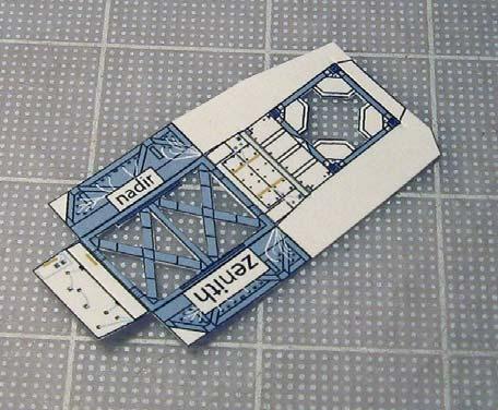
4 J K 5 L 6 M N Red arrows indicate SIDES of S0 truss. From top to bottom: SIDE 1: Keel support and Drag link (A) and 3 DDCUs (B) SIDES 2 and 3: Node 2 umbilicals (C ), Node 3 umbilical (D), spare DDCU (E), forward avionics umbilicals for Destiny (F) and 2 MBSUs (G) SIDE 4: Aft radiator (H), and Segment to Segment Jumpers (I) on side 3 and Port. SIDE 5: Aft struts (J) and Aft tray or Rat s Nest door (K) SIDE 6: Forward struts (L), Module to Truss Structure attach system (M) and 2 MBSUs (N).


5 Starboard Side: showing the Airlock Spur. Port Side: showing the spare DDCU, EVA tools and Segment to Segment Jumpers.


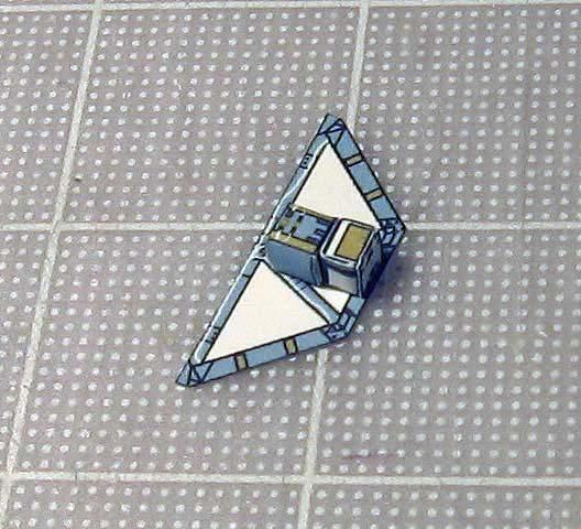
6 Building the S0 truss payload bay version (simple build) For the Payload bay version model, an optional simple S0 truss was designed. Because it will be displayed in the Shuttle s payload bay, it s not important to show the interior of Side 1. To make it more realistic, the red arrow shows the inside of the Aft tray or Rat s nest section. This photo shows how is the inside after gluing the rectangular Aft tray section. Look again at photo on top.


7 Once the whole structure is built, then glue the Mobile Transporter railing section on top of SIDE 1. After this step is done, then it s very simple just to glue the other elements onto the rest of the truss sides. Photos show the outside and inside of the Aft tray door, which is glued on top of the inside section of the Aft tray. (see photo on next page)


8 Photo shows detail of the Avionics Umbilicals for Destiny lab. Just glue each TOP to each BOTTOM, fold and glue onto SIDE 2. Refer to photos to know the exact location. NOTE: These umbilicals are assembled the same way for both scale models with the exception that for the space station versions, these are glued to Destiny.
. These are the station GPS antennas.")

9 When gluing these umbilicals, be careful not to glue on top of the 4 circles (black arrow). These are the station GPS antennas. The rectangular areas with an arrow indicate the location where the MBSU boxes are placed. Just match the direction of the arrow on the corresponding MBSU boxes before you glue. (see next photo)


10 Photo also shows where the Keel support and Drag link are glued (arrows) The Module to Truss structure attach system is glued on this photo as well.


 EVA tools.")


11 Note the building steps to assemble the Module to Truss structure attach system. It applies for both scales. Glue on top of a white line in the gray area (arrow) EVA tools. For the 1:100 scale model, these are glued. These are the support triangular parts for the Segment to Segment Jumpers. This applies to both scales.

.")
12 SEGMENT TO SEGMENT JUMPER CONFIGURATIONS This is the launch configuration for these jumpers. This is the way it looks when the model is placed on the payload bay and when the S0 truss is placed on top of Destiny for this mission only. Note there are 2 jumpers or cables on each side. There are a total of 4 jumpers. This is the configuration after the S0 is glued to the S1 truss (STS-112 mission). Note which cables are still seen on the S0 truss: on the left, it s the outer cable; and on the right or Port side, the inner cable remains. On mission STS-113 (P1 truss), there should be no cables left on the S0 truss.


13 Note the cover for the spare DDCU box. This is only for the payload bay version. Note the position of the Node 3 umbilical tray (future STS-130 mission) It is optional to glue it until STS-130 mission, if not do not glue it. As a reference point, match the tip of the trunnion with the tip of the Node 3 umbilical.


14 Assembly of the Node 2 umbilicals A These are the parts to build each of the Node 2 umbilical. This applies to both scales. Photo shows the 1:100 scale version.

.")

15 This photo shows part A of the Node 2 umbilical. Notice that is folded inwards. The final product looks like the blue part from the photo below (arrow). The 1:144 scale version of the Node 2 umbilical is much simpler but follows the same steps.


16 These parts are used only during folded position. Note how the tip is twisted in an angle.

.")
17 Note the position of the Node 2 umbilicals on the S0 truss for the payload bay version of the model for reference when gluing these parts. IMPORTANT: these umbilicals should not be glued to S0 after mission STS-120, because these will be glued to Node 2 module. Another element to glue is the EV-CPDS box (arrow). For the payload bay version is only a triangular box, but for the space station version a different part is used.


18 Building the S0 truss Space Station version S0 exterior The building steps are similar for both scales. Important to fold this section as photo shows.
. Similar for both scales.")

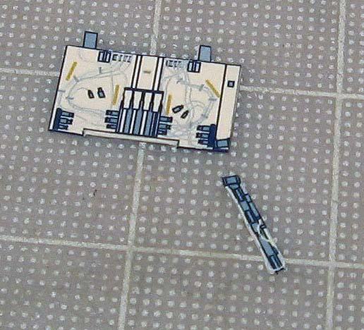
19 S0 interior This is the inside of the S0 truss (draft 1:144 model). Similar for both scales. Match the triangular boxes following the direction of the arrows and glue them. These boxes are the same for both scales.
.")
.")
20 Now glue the Trailing Umbilical system cable reel on top and bottom. Optional details are the boxes drawn (black arrows). You can leave it as it is or build similar 3D boxes and glue on top of the drawings for more realism. (ONLY FOR 1:100 SCALE). This is the time to do this step otherwise it would be very difficult to glue the boxes once the S0 truss is finished. Finished model showing boxes inside.


21 Another detail is this opening only for the 1:100 scale model. This opening is covered by a part that is glued from inside of the truss.

, and the black area")
22 This is one of the interior walls of the truss. Each wall is different in details. In order to correctly glue them in the truss, the side that has the 4 little golden marks should face forward (arrows), and the black area where the red arrow is will indicate that that corner points down.


23 Test model showing the interior walls placed in between the triangular boxes. Another view from inside of the truss. One can only imagine the complexity of the real truss.


24 Now glue this part (arrow) on the outer face matching the openings. Now build each one of the DDCU boxes (white box) and glue following the direction of the arrow to the darker box or boilerplate box. There are 3 sets of DDCU boxes.


25 This is where the 3 rd DDCU box is glued.


26 All 3 DDCU boxes in place. For the 1:100 scale version, both boxes are glued together to a rectangular base (arrow)


27 Draft model showing both the exterior and interior parts of the truss. Put glue on SIDE 4 and on the inside of the exterior opening.


28 Glue on top


29 Add these parts A and B. Closeup view Now the assembly of the Aft tray.


30 This section is the aft umbilical tray for the S0 truss. In the real truss, these are the connections between the S0 and the Z1 truss, and it s been known as the Rat s Nest. Assembly of the supports or struts This is one of the forward struts of the S0 truss. This is for the 1:144 model only. It s a very simple approach in the design.


31 Note location of the Drag links on the space station version model. Note the orientation and positioning of the struts.


32 Note the position of the aft struts on top of SIDE 5. Photo below shows how the struts are folded as tripods. TIP: Fold the strut as shown matching the shortest leg with the longest one. Then open the strut as a tripod element.


33 Also note the location of the keel triangular supports on the Starboard side of the S0 truss for the space station version only.


34 A different approach in the design was done for the 1:100 scale version struts.


35 Building the space station First build the Avionics umbilicals for Destiny lab in order to place the S0 truss on top of Destiny. Note location of the Starboard and Port connector panels for the Avionics umbilicals for Destiny. (red arrows)
.")
 Third, glue the tip of each umbilical to each connector")
36 First glue the Mobile to Truss structure attach system to the Lab Cradle on top of Destiny (red arrow). Second, glue each of the Avionics umbilicals on each side of Destiny (yellow arrows) Third, glue the tip of each umbilical to each connector panels on S0 (light blue arrows) Closeup view
")


37 Now place and glue each of the forward struts (V parts) The S0 truss needs to be straight. Then start gluing the aft struts. Photo shows a draft version of one of the struts.

 2")
38 A view from the Port side showing a draft version of the aft struts. In general, the struts need to be glued as a tripod converging onto a small gray area on the aft section of Destiny (arrow) Smallest strut 2- Medium strut 3- Longest strut


.")
39 Building the Airlock Spur Note location where the Airlock Spur is glued to the S0 truss. (red arrow) The tip of the Airlock Spur is bent 90 degrees inwards and glued to a tiny black dot at the end of a handrail on the Quest airlock (blue arrow). Note that the handrail is at the level of the NASA logo on Quest.

40

41 Umbilicals for Node 2 (post mission STS-120) The Node 2 umbilical is actually glued on top of the Destiny umbilical. Note where both ends are glued.


42 Note the upward orientation of the umbilical on each side. Adding the EV-CPDS box


43 Building the Mobile Transporter (1:100 model shown) TIP: Leave the white areas in order to cut the inner part.


44 Place the interior walls. Place the 4 triangular supports. The Grapple Bar is glued perpendicularly on top of the middle wall.


45


46 Note position of the radiator and the small box in front of the railcar.


47 This railcar model was not designed to be glued to S0 s Side 1 face. Instead, the 2 flaps shown here will attach the railcar to the truss. Note the location of the other boxes. The 1:144 model is a simple box and has no inner walls.


48 REFERENCE PHOTOS Note location of KU-band antenna that is glued on the tab from the right payload bay door.


49

50


51


52 Enjoy!
Assembly Instructions for STS-97 payload (P6 Truss)
") 2008 Assembly Instructions for STS-97 payload (P6 Truss) Familiarization with P6 Truss sides This is the FORWARD side of P6. It is the side that will be facing forward on top of the Z1 truss. Easily identified
2008 Assembly Instructions for STS-97 payload (P6 Truss) Familiarization with P6 Truss sides This is the FORWARD side of P6. It is the side that will be facing forward on top of the Z1 truss. Easily identified
Leopard-class Dropship
 Leopard-class Dropship By Dog Hair Terrain (For use with Battletech, Mechwarrior: Dark Age, or 6mm/1:285 micro armor games) Printing. This model was designed to be printed on 8 ½ x 11 paper. It should
It is also possible to make a more traditional version of the design - which I call Easy Glider - which can be launched by hand in the normal way.
 The Kendal Flyer Designed by David Mitchell The Kendal Flyer is a rubber band launched plane that I designed in 1990. It is possible to make a pure origami version but I prefer this one in which the nose
Mike Hungerford's notes on building Ron Caudillo's TOS Enterprise
 Ron Caudillo, designer of this model, has kindly given his approval for release of my redraw/repaint/rework of it. The colors chosen for the model are subdued approximations of the colors found on the
MAN-032 Rev 0. Performance Designs Zero Packing Manual
 Performance Designs Zero Packing Manual Packing your PD ZERO Before you begin packing, please first review PD s Ram-Air Parachute Owner s Manual. Pay careful attention to the warning/ discussion on pages
The Abracadabra of Engineering: Strong Structures from Flimsy Materials
 The Abracadabra of Engineering: Strong Structures from Flimsy Materials Rockets are great for blasting spacecraft into orbit or on their way to another planet. But the trouble with rockets is that they
Ships of the world : Esmeralda : Assembly Instructions
 http://www.canon.com/c-park/ Before starting assembly: Writing the number of each section on its back side before cutting out the sections is highly recommended. (* This way, you can be sure which section
Chapter 13. ANTY: the robotic ant
 Chapter 13. ANTY: the robotic ant By now, you ve gotten the hang of building models that move on wheels. Another fun, but slightly more challenging, kind of model you can build is an animal robot that
Table of Contents FIRST 2005 FIRST Robotics Competition Manual: Section 3 The Arena rev B Page 1 of 8
 Table of Contents 3 THE ARENA...2 3.1 OVERVIEW...2 3.1.1 Dimensions and Tolerances...3 3.2 PLAYING FIELD...4 3.2.1 Boundaries and Markings...4 3.2.2 Goals...5 3.2.3 Center Goal...5 3.2.4 Tetra Loading
Sail Chart Drafter for Deckman v.2
 Sailing Performer present Sail Chart Drafter for Deckman v.2 This application has been made to help navigators and trimmers to find the right sail to use in a faster and easier way than ever. Sail Chart
THE AMERICAN BARN DOOR KITE
 THE AMERICAN BARN DOOR KITE Oregon Kitemaker s Retreat January 2007 Rod Beamguard 4104 NW 112 th Way Vancouver, WA 98685-3578 (360) 574-8050 home (360) 750-9833 office kytfevr@wa-net.com PLANFORM BARN
STEP 1 A. Lay the two Motor Mount Tubes on a flat surface with ends even and Glue them together with White Glue. Allow Glue to set before moving on.
 Prod. No. A51003 Skill Level Three QUEST AEROSPACE, INC PO Box 2409 Pagosa Springs, CO 81147 800-858-7302 Things You ll Need To Assemble this Kit: Pencil and Hobby Knife: White Glue: Aliphatic Resin glue,
Ships of the world : Cutty Sark : Assembly Instructions
 http://www.canon.com/c-park/ Before starting assembly: Writing the number of each section on its back side before cutting out the sections is highly recommended. (* This way, you can be sure which section
The Collapsible Cube is a tube that twists into a cube, which will collapse flat for storage in two directions.
 Pocket Rhombic Tetrahedron and Collapsible Cube Designed by David Mitchell Pocket Rhombic Tetrahedron Collapsible Cube The Pocket Rhombic Tetrahedron is a simple variation of my Pocket Tetrahedron design
Bob's Card Models and [Resources]
![Bob's Card Models and [Resources]](/thumbs/74/69776662.jpg "Bob's Card Models and [Resources]") Bob's Card Models http://www.bobscardmodels.altervista.org/ and www.zealot.com [Resources] Savoia-Marchetti S.55 1:72 The Savoia-Marchetti S.55 was a double-hulled flying boat produced in Italy beginning
Bob's Card Models http://www.bobscardmodels.altervista.org/ and www.zealot.com [Resources] Savoia-Marchetti S.55 1:72 The Savoia-Marchetti S.55 was a double-hulled flying boat produced in Italy beginning
Place a rope coil here
 1 2 3 4 The anchor buoys were made from Sculpey. You could however, carve them from wood but I wanted to continue my experimentation with this material. A buoy from this time period would have ranged from
Samurai Armor Set: Step by Step
 Samurai Armor Set: Step by Step Pack 6 Stages -5 Contents Stage Pages 7-76 The tasset plates and shoulder pad Stage Pages 77-8 The tassets, helmet and helmet lining Stage Pages 8-86 The tasset plates and
Building a Rocket (Advanced) Before you build a rocket try the bottle on the launcher to test if it holds pressure and fits correctly.
 Before you build a rocket try the bottle on the launcher to test if it holds pressure and fits correctly.") You Will Need 3X 2ltr Bottles 1X Paper lip 1X Glue/Double Sided Tape 1X ardboard 1X Bin Liner 1X Roll of Fishing Line or Thin s Sheets of Paper Side A of Fin 1X Hot Glue Gun 1X Pair of Scissors 1X Fine
You Will Need 3X 2ltr Bottles 1X Paper lip 1X Glue/Double Sided Tape 1X ardboard 1X Bin Liner 1X Roll of Fishing Line or Thin s Sheets of Paper Side A of Fin 1X Hot Glue Gun 1X Pair of Scissors 1X Fine
KaZoon. Kite Kit. User Guide. Cautionary and Warning Statements
 KaZoon Kite Kit User Guide Cautionary and Warning Statements 56799 V0717 This kit is designed and intended for educational purposes only. Use only under the direct supervision of an adult who has read
aero naut Electric Model Aeroplane Quido Order-No. 1303/00
 aero naut Electric Model Aeroplane Quido Order-No. 1303/00 Quido is a small model that accompanies you wherever you go. The prefabricated parts are mostly balsa and just need to be assembled according
Learning to Fly: The Wright Brothers Adventure EG GRC 39
 Learning to Fly: The Wright Brothers Adventure EG 2002 12 007 GRC 39 The Wright Brothers 1900 aircraft was flown repeatedly at Kitty Hawk, North Carolina, during the fall of 1900, mostly as a kite but
Stevenson Projects Building the Hull Top Deck and Bulkheads
 Stevenson Projects Building the Hull 1. Print out both piece sheets. 2. Cut out one keel piece and glue it to a piece of balsa wood or dense cardboard. Cut out the second keel piece and glue it to the
Mount the actuator in the bracket provided and install a 24-foot EFTC cable to the actuator.
 . Mount the actuator in the bracket provided and install a 4-foot EFTC cable to the actuator. Route the cable through left stanchions,, and 4. Be sure that the cable does not contact any spring or push
SERIES 2 RAMP OWNER S MANUAL TOOLS REQUIRED: BEFORE YOU BEGIN... Read and understand these instructions before beginning a ramp setup.
 SERIES 2 RAMP OWNER S MANUAL BEFORE YOU BEGIN... Read and understand these instructions before beginning a ramp setup. Use caution and care for your back when lifting, pushing, pulling, folding or unfolding
2. Bisect the middle 4 right angles with valleycreases. 5. Crease bisectors, stopping where shown. Then swing flaps around.
 $ Dragonfly, version 2 This model s design borrows from Robert Lang s dragonfly in The Complete Book of Origami (Dover, 1988). For your first attempt, begin with a 3x7 rectangle considerably larger than
RUDDER KIT INSTRUCTIONS
 A I N S T R U C T I O N S RUDDER KIT INSTRUCTIONS TARPON 0/40/60/60i The Tarpon series is designed as a high performance sit-on-top kayak tailored for the sport paddler. Our rudder system is designed to
Pre-Paint>Fuselage>Empennage>Fit vertical tail fin. Objectives of this task: Materials and equipment required: Fit the spar extender
 Pre-Paint>Fuselage>Empennage>Fit vertical tail fin Objectives of this task: To fit the vertical tail fin to the fuselage, including fitting the static probe, static tube, optional strobe light wiring and
SPECIAL THANKS TO THE FOLLOWING PEOPLE FOR THEIR HELP IN THIS PROJECT!
 The Viper Mark VII is the state of the art fighter of the Colonial Fleet. It is sleeker and more modern than the Viper Mark II. The Mk7 is designed for both space and atmospheric environments and is also
Falcon 3 145, 170, 195 and Tandem Owner / Service Manual
 Falcon 3 145, 170, 195 and Tandem Owner / Service Manual January 2007 - Second Edition Removing The Sail From The Airframe And Short Packing The Glider Many maintenance and repair procedures will require
KNARR. SCALE: 1/35 length: 440mm width: 300mm height: 400mm
 KNARR SCALE: 1/35 length: 440mm width: 300mm height: 400mm HISTORY: The Knarr is a type of Viking ship which serves for long trade naval business. The Knarrs were very robust and very well resist against
Tiling And Filling The Pool Student Materials Page 1 of 12
 The Pool Part A At last, your parents have finally agreed that it might be possible to put a small pool in the back yard. The only catch is, your parents are very busy and don t have time to spend figuring
Make Your Own Bundled canes Revision Date: May 2014
 Make Your Own Bundled canes Revision Date: May 2014 Attribution-ShareAlike 4.0 International (CC BY-SA 4.0) Summary: http://creativecommons.org/licenses/by-sa/4.0/ License: http://creativecommons.org/licenses/by-sa/4.0/
Loads, Structures, and Mechanisms. Team C5 Matthew Marcus Chris O'Hare Alex Slafkosky Scott Wingate
 Loads, Structures, and Mechanisms Matthew Marcus Chris O'Hare Alex Slafkosky Scott Wingate Presentation Overview Design requirements Initial crew capsule design choice Pressure vessel design Pressure loads
Unit 4. Triangle Relationships. Oct 3 8:20 AM. Oct 3 8:21 AM. Oct 3 8:26 AM. Oct 3 8:28 AM. Oct 3 8:27 AM. Oct 3 8:27 AM
 Unit 4 Triangle Relationships 4.1 -- Classifying Triangles triangle -a figure formed by three segments joining three noncollinear points Classification of triangles: by sides by angles Oct 3 8:20 AM Oct
Samurai Armor Set: Step by Step
 Samurai Armor Set: Step by Step Pack 3 Stages 9-12 1 Contents Stage 9 Pages 29-31 The cuirass side and tassets Stage 10 Pages 32-37 The shoulder plate and tassets Stage 11 Pages 39-41 The shoulder plate
Start the Polars program and load this file by using the explorer tab on the left side. You will get following picture:
 How to create polar curves from logged data? Tacsail uses as a reference the polar targets which are stored in the NMEA2.ini file located in the main Tacsail folder (see also the Tacsail Manual para 5.3.3
INSTRUCTIONS FOR CHAIN LINK INSTALLATION
 INSTRUCTIONS FOR CHAIN LINK INSTALLATION This guide explains how to correctly install our chain link fencing and post system. The guide provides details of which post type you will need for your fence
NAVIGATOR PROP BUILDING INSTRUCTIONS & PHOTOS
 NAVIGATOR PROP BUILDING INSTRUCTIONS & PHOTOS Science under the ice Ice sheet At regional competitions the ice is simulated by 8 ft x 4 ft ½-inch foam sheeting (Home Depot part #703990 [in store only],
Featuring Coats Dual Duty XP. Supplies
 Halloween Black Cat Basket Technique: Designed By: Skill Level: Crafting Time: Finished size: Sewing, Fabric Crafting Linda Turner Griepentrog Intermediate An evening 6" (15.24cm) (at base) x 3 1 2" x
Exxtacy. Repair and Tuning Manual. Exxtacy Construction Basics
 1 of 20 Exxtacy Repair and Tuning Manual Construction Basics D Cell Repair Rib Repair Tuning Exxtacy Construction Basics The Exxtacy is built with carbon fiber and Kevlar/Aramide honeycomb. The Exxtacy
Butler Parachute Systems, Inc
 Butler Parachute Systems, Inc A division of Butler Parachute Systems Group, Inc. TT-600 GEN 1 & 2 TETHERED TANDEM BUNDLE DELIVERY SYSTEM ASSEMBLY MANUAL 1 JUN 2010 INTRODUCTION This manual contains all
Bob's Card Models and [Resources]
![Bob's Card Models and [Resources]](/thumbs/90/103692932.jpg "Bob's Card Models and [Resources]") Bob's Card Models www.bobscardmodels.altervista.org and www.zealot.com [Resources] Robin DR400-140B Major 1:25 The Robin sport monoplane, conceived by Pierre Robin and Jean Délémontez. The Robin DR400
Bob's Card Models www.bobscardmodels.altervista.org and www.zealot.com [Resources] Robin DR400-140B Major 1:25 The Robin sport monoplane, conceived by Pierre Robin and Jean Délémontez. The Robin DR400
Horizontal Fuselage. Top Vertical Fuselage 1. Lay out the Top Vertical Fuse Front(1), Top Vertical Fuse Back(2), and Vertical Stabilizer(3).
, Top Vertical Fuse Back(2), and Vertical Stabilizer(3).") Rumbuilder 71 B-17 Congrats on your Rumbuilder B-17! We re glad you chose to fly with us! If you have any problems, or missing/broken kit pieces, please contact us. We d be happy to replace any damaged
Rumbuilder 71 B-17 Congrats on your Rumbuilder B-17! We re glad you chose to fly with us! If you have any problems, or missing/broken kit pieces, please contact us. We d be happy to replace any damaged
Vikings ship GOKSTAD, 9 th century Scale: 1/72 Length: 305mm Width: 135mm Height: 182mm
 Vikings ship GOKSTAD, 9 th century Scale: 1/72 Length: 305mm Width: 135mm Height: 182mm HISTORY: This model represents a Viking ship found in year 1880 near village Gokstad in Norway. The ship was built
Miss Mayflower. Build Manual
 Miss Mayflower Build Manual Thank you for the purchase of the Miss Mayflower, this new exciting craft will give you fun on many types of terrain including snow, gravel, pavement, grass, water, and when
Bald eagle (Haliaeetus leucocephalus)
") Bald eagle (Haliaeetus leucocephalus) The bald eagle is one of the larger types of eagle, its body measuring between 76 and 92cm, and its wingspan can reach more than two meters. Its dark brown body and
Bald eagle (Haliaeetus leucocephalus) The bald eagle is one of the larger types of eagle, its body measuring between 76 and 92cm, and its wingspan can reach more than two meters. Its dark brown body and
Human Factors and Habitability
 Human Factors and Habitability Discussion of Midterm Required Crew Volumes Human Physiological Adaptation to 0G Workstation Design Restraint Design Ideal Cabin Layout Habitability in Partial Gravity Stowage
THE ARENA TABLE OF CONTENTS 6 THE ARENA OVERVIEW Dimensions and Tolerances... 2
 Section 6 THE ARENA TABLE OF CONTENTS 6 THE ARENA... 2 6.1 OVERVIEW... 2 6.1.1 Dimensions and Tolerances... 2 6.2 PLAYING FIELD... 4 6.2.1 Boundaries and Markings... 4 6.2.2 The RACK... 5 6.3 GAME PIECES...
BMW Motorrad. Installation Instructions. BMW Motorrad Communications System for Schuberth C3
 BMW Motorrad Installation Instructions BMW Motorrad Communications System for Schuberth C3 Order No. 01 29 2 219 831 BMW Motorrad 05/2011 Be sure to read these instructions carefully and completely before
LITTLE TRI construction
 LITTLE TRI construction I have built almost anything that can sail. At the age of 12 my first sail thing, an ice boat. I used skates which had to be mounted on shoes as runners. Big fun, very fast, only
1/600 Scale HMS Leander
 1/600 Scale HMS Leander Royal Navy Frigate Photo-etched detail set to fit the Airfix kit Parts List 1 2 3 4 5 6 7 8 9 10 11 31 32 30 12 13 14 15 16 19 20 21 22 17 18 23 24 26 27 29 37 25 33 34 35 39 36
STUDENT HARNESS-RETRACTABLE Y STRAP INSTALLATION
 INSTRUCT 020 REV 2 Page 1 of 11 5/6/2013 STUDENT HARNESS-RETRACTABLE Y STRAP INSTALLATION INSTRUCT 020 REV 2 Page 2 of 11 5/6/2013 Outline: This document covers two major areas: 1. Retrofit instructions
ClubHub. User s Guide
 ClubHub User s Guide Table of Contents Setup... Initial Club Setup...7 Changing Clubs...5 Settings...8 My Clubs... Turn On/Off Sounds...9 Play Round Mode...0 List View...8 Social Sharing...0 Viewing D
Hansa COG 14 th century SCALE: 1/72 Length: 430mm Width: 210mm Height: 330mm
 Hansa COG 14 th century SCALE: 1/72 Length: 430mm Width: 210mm Height: 330mm HISTORY: The Hansa was a medieval association of German cities which engaged by in long distance business mainly in area of
Friedrich Wilhelm zu Pferde
 TRANSLATION LINKS 1. type into your browser... english+italian+glossary+nautical terms 2. utilise the translation dictionary Nautical Terms & Expressions from Euromodel website An interpretive build of
MANDATORY BULLETIN No.: SAFETY RELATED. EV a SR. Appendix 1 Bulletin Flow Chart
 Appendix 1 Bulletin Flow Chart Form No.: QS-406/F-03A Issue: Date of Issue: Page: 2 APPENDIX 2 Inspection of Nicopress Pressing Tooling: Vernier calliper or Nicopress check gauge Felt-tip pen to mark clamps
Shimano Di2 Installation on S5
 Installing Shimano Dura Ace Di2 Shifting Systems Note these instructions and pictures are for assembling the Shimano Dura Ace Di2 system (Internal Spec) on the Cervélo S5 frame. The Shimano Ultegra Di2
PROVIDING QUALITY SOLUTIONS FOR THE AUDIOMETRIC INDUSTRY
 PROVIDING QUALITY SOLUTIONS FOR THE AUDIOMETRIC INDUSTRY PRODUCT OPTIONS AMB Portable Series: Booths consist of 2 or 3 inch panels with integrated ventilation in the roof and floor. AMB 410: Consists
Trampoline & Enclosure Assembly Instructions
 Trampoline & Enclosure Assembly Instructions Safe user weight 330 lbs (150 kg) Version 718702 The information in this document is subject to change without notice. Copyright Springfree Trampoline Inc.
1/10 th Scale 1956 Ted Jones Classic Hydroplane
 1/10 th Scale 1956 Ted Jones Classic Hydroplane Preparation These plans show outside sheeting of 3/32 balsa laminated with 1/64 birch ply. This makes a light and strong skin for this boat. Optionally you
IAC-06-D4.1.2 CORRELATIONS BETWEEN CEV AND PLANETARY SURFACE SYSTEMS ARCHITECTURE PLANNING Larry Bell
 IAC-06-D4.1.2 CORRELATIONS BETWEEN CEV AND PLANETARY SURFACE SYSTEMS ARCHITECTURE PLANNING Larry Bell Sasakawa International Center for Space Architecture (SICSA), University of Houston, USA e-mail: lbell@uh.edu
OMS P/N: Rev.: B. Description OMS: ASSY BACKUP POD 6.0. DCR# 3137 Date: Operation: Special Instructions: TQC. Torque.
 DCR# Date: -0- ASSY BACKUP POD.0 BPEVE OMS P/N: 00-09 Rev.: B Page: of NA P-Touch Labels Apply Label & Serial Number/Part Number Label onto the front of the chassis as shown. OMS Template: 00-00 Rev. A
Panoptix PS51-TH FrontVü/LiveVü Thruhull
 Panoptix PS51-TH FrontVü/LiveVü Thruhull Transducer Installation Instructions Important Safety Information WARNING See the Important Safety and Product Information guide in the chartplotter or fishfinder
Quadair. Air Hockey Table Owners Manual. Assembly operation and care instuctions. Serial # Distributed By. Sales Person. Technical Service #
 Version 12.1.11 Quadair Air Hockey Table Owners Manual Assembly operation and care instuctions. Serial # Distributed By Sales Person Technical Service # QUADAIR PATENTED WORLDWIDE Forward First, we would
WHITE ENSIGN MODELS. 7. Etched parts 20 are the netted sections of railing that fit to the edges of the mid gun deck extensions, kit parts D25.
 WHITE ENSIGN MODELS RN Littorio-Class Battleships Photoetched Metal details to fit the Trumpeter kits in 1/00 Scale Instructions for working with Photoetched Metal 1. Do not remove the etched parts from
Activity: Because the Earth Turns
 Activity: Because the Earth Turns Introduction: Almost everywhere on Earth (except at the equator), objects moving horizontally and freely (unconstrained) across Earth s surface travel in curved paths.
X-PRESS STAGE SYSTEM OWNER S MANUAL. TOOLS REQUIRED Allen Wrench (provided)
") X-PRESS STAGE SYSTEM BEFORE YOU BEGIN... Read and understand these instructions before operating. Use caution and care for your back when lifting, pushing, pulling, or folding and unfolding these units.
X-PRESS STAGE SYSTEM BEFORE YOU BEGIN... Read and understand these instructions before operating. Use caution and care for your back when lifting, pushing, pulling, or folding and unfolding these units.
The author's TD Coupe, used as a towplane, and the Airhopper. The gas model is equipped with an automatic towline release.
 THE AIRHOPPER BY STANLEY ORZECK PLANS BY PAUL PLECAN An eight-foot sailplane either towed by a gas model or launched by hand tow. The author's TD Coupe, used as a towplane, and the Airhopper. The gas model
Butler Tactical Parachute Systems, LLC
 Butler Tactical Parachute Systems, LLC A division of Butler Parachute Systems Group, Inc. TT-600 TETHERED TANDEM BUNDLE DELIVERY SYSTEM PACKING MANUAL (REVISION A ) Page 1 of 62 INTRODUCTION This manual
Instant Garage 20' x 12' 3" x 8' 3"
 Instant Garage 20' x 12' 3" x 8' 3" Assembly Instructions Description Model # Instant Garage 20' x 12' 3" x 8' 3" - Grey CIG 1220 3503502 Recommended Tools OR THIS IS A TEMPORARY STRUCTURE AND NOT RECOMMENDED
Mapping a Magnetic Field. Evaluation copy. Figure 1: Detecting the magnetic field around a bar magnet
 Mapping a Magnetic Field Experiment 16 The region around a magnet where magnetic forces can be detected is called a magnetic field. All magnets, no matter what their shape, have two poles labeled north
Parts: Included in the parts box: Inner Rear Tire Tray. Inner Front Tire Tray. Trail Doc Clamp. Pivot Assembly. Trail Doc Post.
 NV 2.0 2 Parts: Outer Front Tire Tray Inner Front Tire Tray Outer Rear Tire Tray Inner Rear Tire Tray Pivot Assembly Trail Doc Clamp Trail Doc Post Included in the parts box: 6mm Allen Wrench M6 Lock Washer
Your kit contains the following items. Additional Items You May Need. Pre- cut parts Propeller rigging and rubber Sandpaper Covering sheet
 Your kit contains the following items Pre- cut parts Propeller rigging and rubber Sandpaper Covering sheet The SkyFox offers great glide performance in a rubber powered plane due to its built up wing.
Trampoline & Enclosure Assembly Instructions
 Trampoline & Enclosure Assembly Instructions Safe user weight 250 lbs (115 kg) Version 718602 The information in this document is subject to change without notice. Copyright Springfree Trampoline Inc.
NetSetGO! Coaching Resource Run
 NetSetGO! Coaching Resource Run ANZ NetSetGO! 5-7 Years ANZ NetSetGO! 5-7 years is a play based movement skills program with the emphasis on the acquisition of basic movement skills in a fun environment
In this course you will learn the following
 Module 11 : Example study of robots Lecture 40 : NATARAJ a case study of a 6-legged robot Objectives In this course you will learn the following Mobile Robots Legged Robots Nataraj Robot Nataraj Development
Leg Pouch Pilot Chute System
 Leg Pouch Pilot Chute System User Manual Version 1 Sep 2008 Page 1 Disclaimer: The following information must be read and understood before any use of this equipment. The user knows the risks of skydiving
I Practice Stranger Safety!
 I Practice Stranger Safety! Developing Stranger Safety Awareness Skills Prepared by The Rose Brucia Educational Foundation Draw a circle around the things that help you become AWARE of where you are. Draw
Tugster. Tug Boat. Competition or Sport Tug Kit. A Zippkits R/C Boat. Building Instructions
 Z I P P M A N U FA C T U R I N G Tugster Tug Boat Competition or Sport Tug Kit A Zippkits R/C Boat Building Instructions 2016 JMP Hobby Group St. Paul, Indiana 47272 www.zippkits.com Toll Free (866) 922-ZIPP
Installing a Springer Precision Basepad
 Installing a Springer Precision Basepad Safety First! Although these parts can be changed by almost any gun owner, we strongly recommend that you use a qualified gunsmith/armorer if any part of this instruction
Annex E(M) - Final inspection checklist - monowheel
 - Final inspection checklist - monowheel") Annex E(M) - Final inspection checklist - monowheel A/C Reg... Owner...Kit S/N...Date... (U.K. Only) L.A.A No...Inspector...Insp. No... Note: This check list only covers specific items for inspection of
Annex E(M) - Final inspection checklist - monowheel A/C Reg... Owner...Kit S/N...Date... (U.K. Only) L.A.A No...Inspector...Insp. No... Note: This check list only covers specific items for inspection of
M32 CATAMARAN ASSEMBLY MANUAL
 M32 CATAMARAN ASSEMBLY MANUAL 1 M32 CATAMARAN ASSEMBLY MANUAL MANUAL SUMMARY M32 ASSEMBLY Parts and tools Instructions MAST PLATFORM Parts and tools Instructions MAST STEPPING Instructions MAIN HALYARD
MARIA HF31. SCALE: 1/72 Length: 365 mm width: 85mm height: 295 mm
 MARIA HF31 SCALE: 1/72 Length: 365 mm width: 85mm height: 295 mm HISTORY: Maria HF 31 is a fishing Ewer whose home base was Finkenwerder in northern Germany. Maria HF31 operated in the North Sea for more
Cleopatra British Obelisk Transport Barge. Kartonbau.de Exclusive Edition
 Cleopatra 188 British Obelisk Transport Barge Kartonbau.de Exclusive Edition Copyright 2006 Oliver Weiss / The Walden Font Co. P. O. Box 81, Winchester, MA 01890 www.waldenfont.com Historical Notes The
DQM Annual Hopper QA Checks
 DQM Annual Hopper QA Checks The following document is intended to be a guide for conducting annual Dredge Quality Management quality assurance checks on hopper dredges. The procedures should provide general
Robotic On-Orbit Satellite Servicing: One Size Does Not Fit All
 Robotic On-Orbit Satellite Servicing: One Size Does Not Fit All Dr. David L. Akin Dr. Craig R. Carignan Space Systems Laboratory On-Orbit Servicing Demand by Types Reboost Inspection Dexterous Servicing
LEGO Engineering Conferences ROBOLAB and MINDSTORMS Education Version 4.5 March 2008
 LEGO Engineering Conferences ROBOLAB and MINDSTORMS Education Version 4.5 March 2008 NXT-G Program Book II: Intermediate Robotics Activities for use with the NXT 2008 Tufts Center for Engineering Education
Fiber Optic Lighted Bubbler Spillway Pot (DLP-45) Installation Manual
 Installation Manual") Fiber Optic Lighted Bubbler Spillway Pot (DLP-45) Installation Manual 27.75 23.75 25.50 20.75 Specifications: 8-13 GPM 100 strand fiber - Bubbler 75 strand fiber - Spillway Light Bar 45 ft. fiber tail
Fiber Optic Lighted Bubbler Spillway Pot (DLP-45) Installation Manual 27.75 23.75 25.50 20.75 Specifications: 8-13 GPM 100 strand fiber - Bubbler 75 strand fiber - Spillway Light Bar 45 ft. fiber tail
Product Overview. Product Description CHAPTER
 CHAPTER 1 This chapter provides a functional overview of the Cisco Redundant Power System 2300 and covers these topics: Product Description, page 1-1 Features, page 1-3 Supported Devices, page 1-4 Deployment
Wasp size 2-4. Copyright J:sonSweden AB. Rec. hook Size 10/12
 Wasp size 2-4 Please watch the videos before choosing a specific fly pattern, they explain how to use Detached body pins, Wingburners and Wingmaterials. And how to tie in Wings/Wing-buds and Nymph-legs/Nymph-backs.
How to set up and use DeWiggler Analyst
 The most important mission of an instrument system is correctly reporting wind direction (see http://www.ockam.com/functrue.html). DeWiggler Analyst is an application for determining wind direction change
!""#$%!!!!!!!!!!!!!!! "#$%!&'()*!$%!*(%+!,-!.-'/!()/!.'$*%!%,0($1#,!()/!%2--,#3!!4//!(!%2(''!(2-5),!-.!5&! *'*6(,-0!.-0!'-)1!'*6*'!.'$1#,%3!!!!!!!!
*!$%!*(%+!,-!.-'/!()/!.'$*%!%,0($1#,!()/!%2--,#3!!4//!(!%2(''!(2-5),!-.!5&! *'*6(,-0!.-0!'-)1!'*6*'!.'$1#,%3!!!!!!!!") ""#$% "#$%&'()*$%*(%+,-.-'/()/.'$*%%,0($1#,()/%2--,#34//(%2(''(2-5),-.5& *'*6(,-0.-0'-)1'*6*'.'$1#,%3 70$*),,#*,*2&'(,*8$,#,#*9:;
""#$% "#$%&'()*$%*(%+,-.-'/()/.'$*%%,0($1#,()/%2--,#34//(%2(''(2-5),-.5& *'*6(,-0.-0'-)1'*6*'.'$1#,%3 70$*),,#*,*2&'(,*8$,#,#*9:;
CORO POWER BOAT 3 in 1 Design
 3 in 1 Design A MULTI-PURPOSE COROPLAST BOAT Ideal for all generations to enjoy. Weighs only 20 pounds! Drawn 06-20-2014 Ken Simpson Designs Rev. 09-25-2014 Print in Landscape Mode with ¼ inch borders.
MLV Mast Series Sectional Tripod Mast, 10-34m (32-110ft)
") MLV Mast Series Sectional Tripod Mast, 10-34m (32-110ft) Overview Fully deployed heights of 10, 15, 20, 30 and 34m (32, 49, 65, 98 and 110ft) Heavy duty composite sectional tripod masts capable of supporting
MLV Mast Series Sectional Tripod Mast, 10-34m (32-110ft) Overview Fully deployed heights of 10, 15, 20, 30 and 34m (32, 49, 65, 98 and 110ft) Heavy duty composite sectional tripod masts capable of supporting
2017 Fall Product Program Rally Guide
 2017 Fall Product Program Rally Guide 2017 Fall Product Program Rally Overview QSP and Ashdon Farms are excited to offer Councils, service units and troops the opportunity to host Fall Product Program
H ow To Buil d A Wa ter Rocket
 H ow To Buil d A Wa ter Rocket DESIGN AND DEVELOPMENT Brainstorm The first step in the design of a water bottle rocket is brainstorming. Brainstorming is a problem-solving technique that involves the spontaneous
Making Spars for the Schooner Jeanette
 Making Spars for the Schooner Jeanette..... by Byron Rosenbaum Figure 1. Byron Rosenbaum s 1:16-scale radio-controlled model of the schooner Jeanette. All photographs by the builder. The spars required
Written By: Matt Newsom
 PSP 300xc UMD Door Replacement Replace the UMD door for a PSP 300xc Written By: Matt Newsom ifixit CC BY-NC-SA www.ifixit.com Page 1 of 13 INTRODUCTION Has the UMD door on your PSP 3000c seen better days?
INSTRUCTION MANUAL. January 23, 2003, Revision 0
 INSTRUCTION MANUAL Model 810A In-Vitro Test Apparatus for 310B Muscle Lever January 23, 2003, Revision 0 Copyright 2003 Aurora Scientific Inc. Aurora Scientific Inc. 360 Industrial Parkway S., Unit 4 Aurora,
Instructions for Assembly, Installation, and Operation of the Gas Addition Kit Accessory with the CEM Discover Systems
 Corporation Issued: 5/09 P/N: 600104 Rev. 2 Instructions for Assembly, Installation, and Operation of the Gas Addition Kit Accessory with the CEM Discover Systems The Gas Addition Accessory permits the