CBC2 performance with switched capacitor DC-DC converter. systems meeting, 12/2/14
|
|
|
- Trevor Hodge
- 6 years ago
- Views:
Transcription
1 CBC2 performance with switched capacitor DC-DC converter systems meeting, 12/2/14 1
 1 MHz diff. clock to DC-DC circuit DC-DC DC-DC 1.2 GND(D) 1n DC-DC 1.2V feeds VDDD (dig.")

2 reminder of results from CBC1 +2.5V GND 1n can power CBC from single +2.5V supply 1uF DC-DC diff. clock (CMOS) 1 MHz diff. clock to DC-DC circuit DC-DC DC-DC 1.2 GND(D) 1n DC-DC 1.2V feeds VDDD (dig. supply) and VLDOI (LDO I/P) 1.1V LDO O/P VLDOO feeds analogue stages supply VDDA VDDD alternatively can choose not to use the DC-DC powering all GNDs connected together and just power VDDD from 1.2V DC supply LDO GND(A) VDDA 1n bandgap VLDOO VLDOI 1n 2
3 no. of events no. of events no. of events fixed trig., 1.2V random trig., 1.2V fixed trig., DC-DC random trig., DC-DC 4 41 fixed trig., 1.2V random trig., 1.2V fixed trig., DC-DC random trig., DC-DC fixed trig., 1.2V random trig., 1.2V fixed trig., DC-DC random trig., DC-DC 42 a) Cadded = 1.78 pf b) Cadded = 3.78 pf c) Cadded = 5.79 pf 44 comparator threshold VCTH [mv] DCDC effects on S-curves triggering conditions results fixed trig: random trig. always send trigger at same phase w.r.t. 1 MHz DC-DC clock phase trigger at any random time within DC-DC clock cycle no effects at all if CBC powered from 1.2V DC rail (irrespective of triggering conditions) no effects if CBC triggered at fixed time relative to 1 MHz DC-DC clock phase increasing s-curve distortion with external capacitance if CBC triggered with random phase relationship to 1 MHz 3
4 for largest external capacitance 1 systematic study (DC-DC circuit operating) no. of events Cadded = 5.79 pf acquire s-curves with increasing separation between fast reset time and trigger position (25 nsec steps) not all s-curves in same position 2 plotting s-curve mid-point vs vs. trigger position shows repetitive structure S-curve mid-points [mv] VCTH [mv] [mv rms] separation between positive (or negative) shifts = 4 steps = 1 usec = DC-DC period pedestal shift only, no change in shape => intrinsic unaffected magnitude of effect proportional to external capacitance to ground s-curves in top plot colour coded to show which ones correspond to which point in bottom plot trig. pos'n [ 25 ns steps]
5 summary for CBC1 C f fundamental performance of DC-DC circuit itself is good high efficiency for 2:1 step down conversion no significant effect on intrinsic C EXT but switching transients appear to couple to internal chip ground causing pedestal shifts - magnitudes dependent on external capacitance GND EXT v GND INT worth noting: this would likely not be a problem for hybrid pixel chips low sensor capacitance low inductance bump-bond coupling between sensor and chip grounds 5
6 CBC2 C4 layout, 25um pitch, 19 columns x 43 rows DC-DC powering features retained bandgap, LDO for analogue powering, same as prototype improved step-down DC-DC switched capacitor circuit slower switching edges & rad-hard layout design by Stefano Michelis (CERN) bandgap pipeline + buffering bias gen. 254 inputs CWD, offset correction and colleraltion logic 11 mm 254 amplifier/comparator channels interchip signals DC-DC 5 mm interchip LDO signals 6
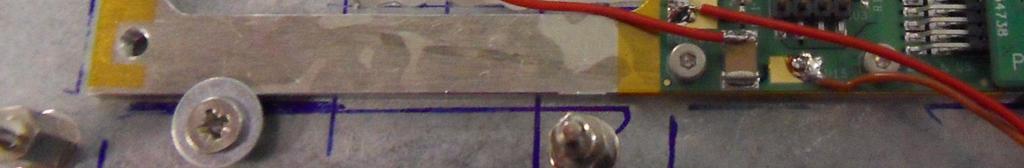
7 start by looking at power rails on scope chip A use diff probe on capacitors C1/C7 2.5 V in C4/C8 DCDC output voltage ~1.2 C3/C5 LDO out ~1.1 chip B 7
8 probing voltages voltage on 2.5 V storage capacitor DC-DC converter out Volts Volts DC-DC converter out LDO out x LDO out LDO out with 1.2V DC input x time 1 x time efficiency measurement DC powering: 2 chips draw 141 ma from 1.21 V => 171 mw DC-DC powering: 73.2 ma from 2.6V => 19 mw => ~9% efficiency 8
9 effect on experimental study results here performed using module#5 one CNM n-on-p sensor only => half of channels see capacitive load of sensor other half channels unbonded interesting to see differences between bonded and un module powered using either: DC: ~1.2 V supplied to VDDD (digital rail) 1.1 V VDDA derived from VDDD via LDO DC-DC: ~2.6 V supplied to switched cap circuit running at 1 MHz DC-DC supplies ~1.2 V VDDD 1.1 V VDDA derived from VDDD via LDO initial triggering conditions pseudo-random triggered readout (i.e. no fast reset between triggers) 1 MHz DC-DC clock provided by external oscillator (not synchronized to 4 MHz) 9


10 module #5 1
11 effect on events over thresh events over thresh S-curves 11 no sensor DC powered sensor channels DC-DC powered comparator threshold VCTH 14 rms VCTH units DC-DC DC sensor channels no sensor results for chip A here - results for chip B look the same significant increase for DC-DC powering channel no. 11
12 study more systematically synchronize 1 MHz DC-DC clock with 4 MHz include fast reset in trigger sequence look at s-curve dependence on fast reset - trigger separation increase separation in 25 ns steps (, 1, 2, 3, 43, 44, 45) to cover complete 1 MHz period starting separation fast reset 1 MHz t r I g g e r

13 systematic s-curve study - chip A * * * * * * * *
14 systematic s-curve study - chip B * * * * * * * *
15 explanatory key to following 44! slides s-curve mid-points 25ns step value CBC2A CBC2B CBC2A CBC2B CBC2A CBC2B CBC2A CBC2B CBC1 results suggest to look for systematic pedestal shifts - can see that from s-curve mid-point plots in 4 leftmost panels 4 rightmost panels show calculated from s-curves 15
16 s-curve mid-points 1 16
17 s-curve mid-points 2 17
18 s-curve mid-points 3 notice common-mode pedestal shifts 18
19 s-curve mid-points 4 notice common-mode pedestal shifts 19
20 s-curve mid-points 5 notice common-mode pedestal shifts 2
21 s-curve mid-points 6 21
22 s-curve mid-points 7 22
23 s-curve mid-points 8 23
24 s-curve mid-points 9 24
25 * s-curve mid-points 1 pedestal shift varies across chip - same shape for both chips 25

26 s-curve mid-points 11 26
27 * s-curve mid-points 12 pedestal shift varies across chip - same shape for both chips 27
28 * s-curve mid-points 13 pedestal shift varies across chip - same shape for both chips 28
29 * s-curve mid-points 14 pedestal shift varies across chip - same shape for both chips 29
30 s-curve mid-points 15 3
31 s-curve mid-points 16 31
32 s-curve mid-points 17 32
33 s-curve mid-points 18 33
34 s-curve mid-points 19 34
35 s-curve mid-points 2 35
36 s-curve mid-points 21 36
37 s-curve mid-points 22 37
38 s-curve mid-points 23 38
39 s-curve mid-points 24 39
40 s-curve mid-points 25 4
41 s-curve mid-points 26 41
42 s-curve mid-points 27 42
43 s-curve mid-points 28 43
44 s-curve mid-points 29 44
45 * s-curve mid-points 3 pedestal shift varies across chip - same shape for both chips same shape as step 1 (5 nsec previous) 45
46 s-curve mid-points 31 46
47 * s-curve mid-points 32 pedestal shift varies across chip - same shape for both chips same shape as step 12 (5 nsec previous) 47
48 * s-curve mid-points 33 pedestal shift varies across chip - same shape for both chips same shape as step 13 (5 nsec previous) 48
49 * s-curve mid-points 34 pedestal shift varies across chip - same shape for both chips same shape as step 14 (5 nsec previous) 49
50 s-curve mid-points 35 5
51 s-curve mid-points 36 51
52 s-curve mid-points 37 52
53 s-curve mid-points 38 53
54 s-curve mid-points 39 54
55 s-curve mid-points 4 55
56 s-curve mid-points 41 56
57 s-curve mid-points 42 57
58 s-curve mid-points 43 58
59 s-curve mid-points 44 59
60 s-curve mid-points 45 6
61 average s-curve mid-point vs. time step CBC2A CBC2B ~ 1 VCTH units (~ 25 mv) sensor channels sensor channels CBC2A CBC2B ~ 6 VCTH units (~ 15 mv) periodicity of pedestal shift behaviour 5 nsec (1/2 the 1 MHz clock period) amplitude of pedestal movement vs. trigger time depends on whether channel bonded or not 61

62 average vs. time step CBC2A CBC2B 7 reminder of random trigger result 6 DC-DC 5 CBC2A sensor channels CBC2B sensor channels rms VCTH units DC channel no. some variation of intrinsic with time-step (could just be due to non-linearities in VCTH) but dominant extra (with DC-DC powering) coming from pedestal movement 62
63 CBC1:CBC2 comparison 1 no. of events Cadded = 5.79 pf >1 mv CBC2A ~25 mv 2 sensor channels S-curve mid-points [mv] VCTH [mv] [mv rms] CBC2A sensor channels trig. pos'n [ 25 ns steps]
64 summary like CBC1, fundamental performance of DC-DC circuit is good high efficiency for 2:1 step down conversion no significant effect on intrinsic systematic pedestal shift effects remain much smaller in amplitude than for CBC1 characteristic behaviour different pedestal shifts vary ~continuously throughout 1 MHz DC-DC cycle (not just at clock edges) across chip pedestal shift variation at certain phases 64
65 some slides from previous CBC1 talk follow 65
66 CBC performance with switched capacitor DC-DC converter Mark Raymond, Tracker Upgrade Power Working Group, February
67 CBC power features 2 powering features included on CBC prototype pads for test features 2.5 -> 1.25 DC-DC converter LDO regulator (1.2 -> 1.1) feeds analog FE provides stable voltage rail and supply rejection 2.5 -> 1.2 DC-DC converter allows to power CBC using single 2.5 V rail thanks to Michal Bochenek and Federico Faccio for the design and help with incorporating the layout into the CBC 7 mm amplifiers & comparators TEST DEVICES 256 deep pipeline + 32 deep buffers power SLVS data clock trigger I 2 C, reset power LDO bandgap pads for test features 4 mm bias generator 67
68 CBC power features - DC performance 1.25 DC-DC switched capacitor converter DC-DC & LDO outputs converts 2.5 -> ~ 1.2 clearly functioning, high efficiency ~ 9% study of DC-DC switching effects on follows in next slides Volts LDO input LDO output LDO linear regulator provides clean,regulated rail to analog FE ~ 1.2 Vin, 1.1 Vout dropout ~ 4 mv for 6 ma load provides > 3dB supply rejection up to 1 MHz for further details see: CBC_Tracker_Electronics_May_11.pdf 1.5 LDO dropout LDO output [V] us / division 4 mv 1.1 3mA load 6mA load 1.15 LDO input voltage [V]
 and VLDOI (LDO I/P) 4 external capacitors minimum (actually 5 in this picture) CBC on test board GND +2.5 GND DC-DC 1.")
69 +2.5V GND 1n 1uF DC-DC DC-DC diff. clock (CMOS) DC-DC 1.2 GND(D) VDDD all GNDs connected together 1n DC-DC powering option can power CBC from single +2.5V supply 1 MHz diff. clock to DC-DC circuit DC-DC 1.2V feeds VDDD (dig. supply) and VLDOI (LDO I/P) 4 external capacitors minimum (actually 5 in this picture) CBC on test board GND +2.5 GND DC-DC 1.2 LDO GND(A) VDDA 1n bandgap VLDOO VLDOI 1n GND GND BGI linked (or not) to BGO maybe don t need this cap 69
70 adding external capacitance want to measure (from s-curves) dependence on external capacitance plug-on boards containing arrays of capacitors connect to bonded out channels acquire s-curve for one of the bonded out channels GND individual channel capacitors GND GND 7
71 no. of events a) Cadded = 1.78 pf s-curves:reference measurement fixed trig., 1.2V b) Cadded = 3.78 pf measure s-curves for single channel for different external capacitances conditions for measurements on this slide no. of events fixed trig., 1.2V digital circuitry supplied with external 1.2 V supply DC-DC not running CBC triggered at fixed time following a fast reset c) Cadded = 5.79 pf => always triggering same pipeline location gives cleanest possible measurement as reference no. of events fixed trig., 1.2V (no reason to expect any effect from random triggering, but just to check) comparator threshold VCTH [mv]
72 no. of events fixed trig., 1.2V random trig., 1.2V 4 41 a) Cadded = 1.78 pf b) Cadded = 3.78 pf 44 s-curves: DC supply (random trigger) now repeat for random triggering digital circuitry still supplied with external 1.2V supply DC-DC still not running but fast reset removed no. of events fixed trig., 1.2V random trig., 1.2V pseudo-random trigger, so now triggering locations throughout pipeline no effect on s-curves visible (i.e. no effect on ) c) Cadded = 5.79 pf (as expected) 8 no. of events fixed trig., 1.2V random trig., 1.2V comparator threshold VCTH [mv]
73 no. of events fixed trig., 1.2V random trig., 1.2V fixed trig., DC-DC 4 41 a) Cadded = 1.78 pf b) Cadded = 3.78 pf 44 s-curves: DC-DC running (fixed trigger time) now feed digital circuitry with DC-DC 1.2 V DC-DC now running return to triggering at fixed time following a fast reset no. of events fixed trig., 1.2V random trig., 1.2V fixed trig., DC-DC DC-DC clocked at 1 MHz with fixed phase relationship to fast reset once again - no significant effect on s-curves c) Cadded = 5.79 pf 44 => DC-DC circuit doesn t affect intrinsic 8 no. of events fixed trig., 1.2V random trig., 1.2V fixed trig., DC-DC comparator threshold VCTH [mv]
74 no. of events no. of events fixed trig., 1.2V random trig., 1.2V fixed trig., DC-DC random trig., DC-DC 4 41 fixed trig., 1.2V random trig., 1.2V fixed trig., DC-DC random trig., DC-DC 4 41 a) Cadded = 1.78 pf b) Cadded = 3.78 pf c) Cadded = 5.79 pf s-curves: DC-DC running (random trigger) now try pseudo-random triggering again DC-DC still running s-curves now distorted for larger capacitance => something to do with random triggering when DC-DC circuit operating an effect associated with specific pipeline locations? try to understand what s going on with a more systematic study => look at s-curve dependence on triggered pipeline location no. of events fixed trig., 1.2V random trig., 1.2V fixed trig., DC-DC random trig., DC-DC comparator threshold VCTH [mv]
75 s-curve dependence on triggered pipeline loc n 1 8 Cadded = 1.78 pf acquire s-curves with increasing separation between fast reset time and trigger position (25 nsec steps) no. of events 6 4 DC-DC circuit operating results here for smallest capacitance: 2 not all s-curves in same position S-curve mid-points [mv] VCTH [mv] 4 steps [mv rms] plotting s-curve mid-point vs vs. trigger position shows repetitive structure separation between positive (or negative) shifts = 4 steps = 1 µsec = DC-DC period pedestal shift only, no change in shape => intrinsic unaffected trig. pos'n [ 25 ns steps]
76 increasing external capacitance 1 8 Cadded = 3.78 pf effect becomes much more noticeable no. of events VCTH [mv] S-curve mid-points [mv] [mv rms] trig. pos'n [ 25 ns steps]
77 for largest external capacitance 1 no. of events Cadded = 5.79 pf s-curves in top plot colour coded to show which ones correspond to which point in bottom plot some distortion visible for most negatively shifted curves (out of amplifier linear range) VCTH [mv] so DC-DC circuit operation somehow affects channel pedestal magnitude of effect proportional to external capacitance to ground S-curve mid-points [mv] [mv rms] trig. pos'n [ 25 ns steps]
78 repeat for external DC supplies 1 just to check no. of events Cadded = 5.8 pf effect goes away completely if DC-DC circuit not operational VCTH [mv] S-curve mid-points [mv] [mv rms] trig. pos'n [ 25 ns steps]
GOLT! RED LIGHT DISTRICT
 GOLT! RED LIGHT DISTRICT USER MANUAL v2.1 How RLD Works Signal Flow PROCESSOR The timing processor receives all clock signals and start stop commands. Its main function is to determine which timing signals
82C288 BUS CONTROLLER FOR PROCESSORS (82C C C288-8)
") BUS CONTROLLER FOR 80286 PROCESSORS (82C288-12 82C288-10 82C288-8) Y Provides Commands and Controls for Local and System Bus Y Wide Flexibility in System Configurations Y High Speed CHMOS III Technology
BUS CONTROLLER FOR 80286 PROCESSORS (82C288-12 82C288-10 82C288-8) Y Provides Commands and Controls for Local and System Bus Y Wide Flexibility in System Configurations Y High Speed CHMOS III Technology
Non Invasive Stability Measurements vs. Bode Plots
 Comparisons of Non Invasive Stability Measurements vs. Bode Plots AEi Systems 5777 W. Century Blvd. Suite 285, Los Angeles, CA 945 3 26 44 info@aeng.com More Information: https://www.picotest.com/non invasive
VLSI Design 14. Memories
 Last module: Synthesis and Verilog This module Memory arrays SRMs Serial Memories Dynamic memories Memory rrays Memory rrays Random ccess Memory Serial ccess Memory Content ddressable Memory (CM) Read/Write
Exercise 8. Closed-Loop Pressure Control, Proportional-Plus-Integral Mode EXERCISE OBJECTIVE
 Exercise 8 Closed-Loop Pressure Control, EXERCISE OBJECTIVE To understand open and closed-loop pressure control; To learn how to sense the pressure in a pneumatic circuit; To control the pressure in a
Lab 1c Isentropic Blow-down Process and Discharge Coefficient
 058:080 Experimental Engineering Lab 1c Isentropic Blow-down Process and Discharge Coefficient OBJECTIVES - To study the transient discharge of a rigid pressurized tank; To determine the discharge coefficients
CHEMICAL ENGINEERING LABORATORY CHEG 239W. Control of a Steam-Heated Mixing Tank with a Pneumatic Process Controller
 CHEMICAL ENGINEERING LABORATORY CHEG 239W Control of a Steam-Heated Mixing Tank with a Pneumatic Process Controller Objective The experiment involves tuning a commercial process controller for temperature
Electromagnetic Attacks on Ring Oscillator-Based True Random Number Generator
 Introduction Attacks on TRNG Our active attack EM analysis Electromagnetic Attacks on Ring Oscillator-Based True Random Number Generator Pierre Bayon, Lilian Bossuet, Alain Aubert, Viktor Fischer François
Adiabatic Switching. A Survey of Reversible Computation Circuits. Benjamin Bobich, 2004
 Adiabatic Switching A Survey of Reversible Computation Circuits Benjamin Bobich, 2004 Agenda for Today 1. The Basics of Adiabatic Logic and the Fundamentals of Adiabatic Charging 2. Early Adiabatic Circuit
CPE/EE 427, CPE 527 VLSI Design I L21: Sequential Circuits. Review: The Regenerative Property
 CPE/EE 427, CPE 527 VLSI esign I L21: Sequential Circuits epartment of Electrical and Computer Engineering University of Alabama in Huntsville Aleksandar Milenkovic ( www.ece.uah.edu/~milenka ) www.ece.uah.edu/~milenka/cpe527-5f
Stand-Alone Bubble Detection System
 Instruction Sheet P/N Stand-Alone Bubble Detection System 1. Introduction The Bubble Detection system is designed to detect air-bubble induced gaps in a bead of material as it is being dispensed. When
TTL Flash Interface connections
 TTL Flash Interface connections Nikon TTL Hot-shoe Interface Gnd = Ground, Earth, Mass, Common. X = X (trigger) contact. Q = Quench or TTL stop. Rdy = Ready to fire SP = Speedlight present (Monitor). The
VLSI Design I; A. Milenkovic 1
 Review: The Regenerative Property V i V o V i V o CPE/EE 47, CPE 57 VLSI esign I : Sequential Circuits epartment of Electrical and Computer Engineering University of labama in Huntsville leksandar Milenkovic
VLSI Design I; A. Milenkovic 1
 CPE/EE 427, CPE 527 VLSI esign I L2: ynamic Sequential Circuits epartment of Electrical and Computer Engineering University of Alabama in Huntsville Aleksandar Milenkovic ( www. ece.uah.edu/~milenka )
Technical Data Sheet MF010-O-LC
 Technical Data Sheet MF010-O-LC - 1 - 1. Properties The oxygen measuring system MF010-O-LC determines the oxygen content in gas mixtures up to a temperature of 250 C. It is particularly suitable for the
Surfing Interconnect
 Surfing Interconnect Mark R. Greenstreet and Jihong Ren University of British Columbia, Rambus Surfing Interconnect p.1/17 Motivation Wires are the problem: Wires scale poorly with feature size: Gate delays
SiPM readout experience and prospects
 SiPM readout experience and prospects Felix Sefkow DESY CALICE collaboration ALCPG workshop at Snowmass August 23, 2005 This talk SiPM mass production and tests Experience with multi-channel readout Future
CONTROL LOGIC DESCRIPTION DOCUMENT IC-410ND
 Configuration # : 41G20F0 CONTROL LOGIC DESCRIPTION DOCUMENT IC-410ND Input/output table: Inputs Qty Outputs Qty Inside Temperature Probe 3 Inflatable Balloon 8 Chimney Temperature Probe 1 Chimney Activator
256/512 /1K /2K/4K x 9 Asynchronous FIFO
 /25/29/ fax id: 5404 Features Asynchronous first-in first-out (FIFO) buffer memories 256 x 9 (CY7C419) 512 x 9 (CY7C421) 1K x 9 (CY7C425) 2K x 9 (CY7C429) 4K x 9 (CY7C433) Dual-ported AM cell High-speed
MEMS Sensors for Smart Living: ITRI Solutions. Chris Chen, ITRI
 MEMS Sensors for Smart Living: ITRI Solutions Chris Chen, ITRI MEMS Sensors for Smart Living Outline Sensors are Everywhere What MEMS Sensors are Most Required Smart Living Megatrend Herald Next Wave of
MANUAL KPS Pressure Control Valve
 TetraTec Instruments GmbH Gewerbestrasse 8 71144 Steinenbronn Deutschland E-Mail: info@tetratec.de Tel.: 07157/5387-0 Fax: 07157/5387-10 MANUAL Pressure Control Valve *** VERSION 1.0 *** Update: 17.11.2006
GATE 2 Part No
 PAGE 1 GATE 2 Part No. 23001125 SWING GATE CTROLLER INSTALLATI GUIDE Page 2 GATE 2 Code No. 23001125 Electronic Control Board for use with SEA Hydraulic or Electro-mechanical swing gate operators (without
CD4008BMS. CMOS 4-Bit Full Adder With Parallel Carry Out. Features. Pinout. Logic Diagram. Applications. Description.
 CD48BMS November 994 CMOS 4-Bit Full Adder With Parallel Carry Out Features Pinout High-Voltage Type (2V Rating) 4 Sum Outputs Plus Parallel Look-ahead Carry-Output CD48BMS TOP VIEW High-Speed Operation
Exercise 1: Control Functions
 Exercise 1: Control Functions EXERCISE OBJECTIVE When you have completed this exercise, you will be able to control the function of an asynchronous ripple counter. You will verify your results by operating
SPIRIT III Radiometer Saturation Effect
 Utah State University DigitalCommons@USU Space Dynamics Lab Publications Space Dynamics Lab 1-1-1997 SPIRIT III Radiometer Saturation Effect Joseph J. Tansock Follow this and additional works at: https://digitalcommons.usu.edu/sdl_pubs
MIL-STD-883G METHOD
 STEADY-STATE LIFE 1. PURPOSE. The steady-state life test is performed for the purpose of demonstrating the quality or reliability of devices subjected to the specified conditions over an extended time
AMS 2710 PCB pressure sensor module with V output
 FEATURES Universal pressure sensor module with 0.. 10 V voltage output Fully calibrated and temperature compensated sensor module Variants for (bidirectional) differential, gage, absolute and barometric
REASONS FOR THE DEVELOPMENT
 7 Series 7 Series +24VDC VDC OUTPUT MICROPROCESS. E P IN EXH OUT 7 Series 7 ø,8 8 7 Series 9 5 8 9 7 Series Display features The proportional regulator has a 3 /2 digit display and a three-pushbutton
Asynchronous, Cascadable 8K/16K/32K/64K x9 FIFOs
 60A CY7C460A/CY7C462A Features Asynchronous, Cascadable 8K/16K/32K/64K x9 FIFOs Functional Description High-speed, low-power, first-in first-out (FIFO) memories 8K x 9 FIFO (CY7C460A) 16K x 9 FIFO (CY7C462A)
660 Multipoint Electronic Level Switch
 660 Multipoint Electronic Level Switch General Instructions The Multipoint Electronic Level Switch is a level sensing device which reads process level by capacitance measurement. Capacitance varies according
MPC5674F PMC Trimming of Internal Regulators and Low Voltage Detection
 Freescale Semiconductor Application Note Document Number: AN4264 Rev. 0, 04/2011 MPC5674F PMC Trimming of Internal Regulators and Low Voltage Detection by: Robert Moran Applications Engineer East Kilbride
SAPCON. User Manual. Capacitance Continuous Level Indicator. . Introduction. . General Description. . Principle of Operation. .
 User Manual Capacitance Continuous Level Indicator Comprehensive User s Manual. Introduction. General Description. Principle of Operation. Specifications. Connection Diagrams. Quick Calibration Chart.
COMPARISON OF DIFFERENTIAL PRESSURE SENSING TECHNOLOGIES IN HOSPITAL ISOLATION ROOMS AND OTHER CRITICAL ENVIRONMENT APPLICATIONS
 COMPARISON OF DIFFERENTIAL PRESSURE SENSING TECHNOLOGIES IN HOSPITAL ISOLATION ROOMS AND OTHER CRITICAL ENVIRONMENT APPLICATIONS APPLICATION NOTE LC-136 Introduction Specialized spaces often times must
Precision level sensing with low-pressure module MS
 The task on hand Level sensing as it is understood in modern process automation is much more than simply "tank half full" or "tank a quarter full". Using suitable sensors, levels, inlets and outlets can
Digital Level Control One and Two Loops Proportional and Integral Control Single-Loop and Cascade Control
 Digital Level Control One and Two Loops Proportional and Integral Control Single-Loop and Cascade Control Introduction This experiment offers a look into the broad field of process control. This area of
control of salinity Thanks to David Hall, from LWTL
 control of salinity Thanks to David Hall, from LWTL DI water (0.0% NaCl) salt water (1.0% NaCl) General Idea The objective is to keep the salinity close to a setpoint which will be provided by your instructor
Oxygen Meter User Manual
 Oxygen Meter User Manual Monday, July 23, 2007 1. Outline...2 2. Program...3 2.1. Environment for program execution...3 2.2. Installation...3 2.3. Un installation...3 2.4. USB driver installation...3 2.5.
LSG Single Point Failure Analysis
 NO. I RIEV. NC j ATM-929 1._&11..1 DATE 5/18/71 The purpose of this ATM is to comment on the results of the single point failure analysis conducted on the lunar surface gravimeter experiment. It is to
Cover Page for Lab Report Group Portion. Pump Performance
 Cover Page for Lab Report Group Portion Pump Performance Prepared by Professor J. M. Cimbala, Penn State University Latest revision: 02 March 2012 Name 1: Name 2: Name 3: [Name 4: ] Date: Section number:
EB/EE. Status: Recent Highlights Status: Interesting re-discovery Status: To-Do List Principal items. Preliminary Shutdown Schedule
 EB/EE Status & Plans Status: Recent Highlights Status: Interesting re-discovery Status: To-Do List Principal items EB/EE Plans for remainder of CRAFT Preliminary Shutdown Schedule 1 Recent Highlights 1)
living with the lab control of salinity 2012 David Hall
 control of salinity 2012 David Hall General Idea The objective is to keep the salinity close to a setpoint which will provided by your instructor The salinity sensor measures the analog voltage output
Proportional pressure regulators VPPE
 Proportional pressure regulators VPPE Proportional pressure regulators VPPE Product range overview Function Version Pneumatic connection Proportional pressure regulator Nominal size for pressurisation/
HW #5: Digital Logic and Flip Flops
 HW #5: Digital Logic and Flip Flops This homework will walk through a specific digital design problem in all its glory that you will then implement in this weeks lab. 1 Write the Truth Table (10 pts) Consider
Long term stability tests of INO RPC prototypes
 Long term stability tests of INO RPC prototypes While the problem of sudden aging in the glass RPC prototypes is being investigated, a few RPCs of dimension 40 cm 30 cm were fabricated, using glass procured
AN ISOLATED SMALL WIND TURBINE EMULATOR
 AN ISOLATED SMALL WIND TURBINE EMULATOR Md. Arifujjaman Graduate Student Seminar: Master of Engineering Faculty of Engineering and Applied Science Memorial University of Newfoundland St. John s, NL, Canada
Inductive Linear Displacement Transducers Model IW 260 Measuring strokes: 80 mm, 170 mm, 240 mm, 360 mm
 Inductive Linear Displacement Transducers Model IW 260 Measuring strokes 80, 170, 240, 360 Document no. IW 100 HE Date 1.07.201 Contactless, robust sensor system Infinite resolution, no hysteresis Calibrated
When buying one of our prototypes you agree with this!
 This ppo2 display unit is just a prototype, using it is not allowed and not our intension. It is for demonstration only. Be always aware that a device like this can and will show wrong data and that can
FUEL GAS FIRING CONTROL RJ (Dick) Perry Safety Systems Consultant 6 June 2016
 Perry Safety Systems Consultant 6 June 2016") INTRODUCTION Fired equipment such as Heaters and Boilers, normally have to comply with either NFPA 85/86 or API 556 for North America and some other countries which apply such standards, or EN 746-2 for
INTRODUCTION Fired equipment such as Heaters and Boilers, normally have to comply with either NFPA 85/86 or API 556 for North America and some other countries which apply such standards, or EN 746-2 for
Analogue and Digital Mass Flow Meters and Controllers for Gases MASS-STREAM
 Analogue and Digital Mass Flow Meters and Controllers for Gases MASS-STREAM M+W Instruments Your partner Key Facts M+W Instruments was founded in 1988 and has always specialised in thermal mass flow meters
DIY - PC - Interface for Suunto Cobra/Vyper/Mosquito
 DIY - PC - Interface for Suunto Cobra/Vyper/Mosquito Summary This document is the distinct consequence of the Spyder/Stinger interface DIY. After having many e-mails concerning the application for the
VLSI Design I; A. Milenkovic 1
 State Registers Review: Sequential efinitis CPE/EE 427, CPE 527 VLSI esign I L2: ynamic Sequential Circuits epartment of Electrical and Computer Engineering University of labama in Huntsville leksandar
All Sixth Sense cells for toxic gas detection are based on electrochemical principles and can be classified as amperometric fuel cells.
 1.1 Two or Three Electrodes? All Sixth Sense cells for toxic gas detection are based on electrochemical principles and can be classified as amperometric fuel cells. The simplest form of electrochemical
THIẾT KẾ VI MẠCH TƯƠNG TỰ CHƯƠNG 2: CMOS Technology
 THIẾT KẾ VI MẠCH TƯƠNG TỰ CHƯƠNG 2: CMOS Technology Hoàng Trang-bộ môn Kỹ Thuật Điện Tử hoangtrang@hcmut.edu.vn 1 TP.Hồ Chí Minh 12/2011 1. Overview - IC technology - CMOS vs BJT Hoàng Trang-bộ môn Kỹ
Lab #1 Pressure: Bubblers and Water Balloons CEE 331 Fall 2003
 CEE 331 Lab 1 Page 1 of 9 SAFETY Lab #1 Pressure: Bubblers and Water Balloons CEE 331 Fall 2003 Laboratory exercise based on an exercise developed by Dr. Monroe Weber-Shirk The major safety hazard in this
IRceL Operating Instructions
 IRceL Operating Instructions IRceL CO2 IRceL CH4 Carbon dioxide sensor Methane sensor Contents Introduction... 2 Evaluation... 2 Performance... 2 Instrument Development... 3 1. Lamp drive circuit... 3
1999 Microcomponents Technology SLYA017A
 Application Brief Number 001 1999 Microcomponents Technology SLYA017A IMPORTANT NOTICE Texas Instruments and its subsidiaries (TI) reserve the right to make changes to their products or to discontinue
![[Instruments for vacuum measurement, checking and adjustment] 3](/thumbs/94/121874202.jpg "[Instruments for vacuum measurement, checking and adjustment] 3")
ELIMINATOR INSTRUCTIONS Table of Contents
 ELIMINATOR INSTRUCTIONS Table of Contents 1. PRACTICE MODE A. Toggling from Full to Pro Tree B. Toggling from 1 to 2 Users C. Toggling from Auto to Manual Reset D. Setting the Delay Boxes E. Setting a
Mitos Fluika Pressure and Vacuum Pumps Datasheet
 Unit 1, Anglian Business Park, Orchard Road, Royston, Hertfordshire, SG8 5TW, UK T: +44 (0)1763 242491 F: +44 (0)1763 246125 E: sales@dolomite-microfluidics.com W: www.dolomite-microfluidics.com Dolomite
A4 Operation Manual. Fig.1-1 Controller Socket Diagram
 A4 Operation Manual Safety Instruction Please read this manual carefully, also with related manual for the machinery before use the controller. For installing and operating the controller properly and
BAPI Pressure Line of Products - FAQs
 Table of Contents 1. Several manufacturers produce pressure transmitters, why should I purchase from BAPI?... p. 2 2. BAPI makes several styles of pressure transmitters. What are the features of each?...
Yoke Instrumentation: ILD Muon System / Tail Catcher. Valeri Saveliev IAM, RAS, Russia DESY, Germany 3 June, 2016
 Yoke Instrumentation: ILD Muon System / Tail Catcher Valeri Saveliev IAM, RAS, Russia DESY, Germany 3 June, 2016 ILD Muon System/Tail Catcher µ - µ + Events/0.2 [GeV] 150 + Zh µ µ - X 100 50 s = 250 GeV
STARLOG. Capacitive Water Depth Probe
 STARLOG Capacitive Water Depth Probe Model 6521 User Manual Supplement 6219 Revision D July 10. 1998 Copyright Notice Copyright Unidata Australia 1998. All rights reserved. No part of this publication
AMS 6916 Board mount pressure sensor with ratiometric analog output
 FEATURES Piezoresistive pressure sensor with amplified analog output Calibrated and temperature compensated Ratiometric voltage output, 0.5 4.5 V Digital signal conditioning, 12 bit output resolution Differential,
A4s Operation Manual
 A4s Operation Manual Safety Instruction Please read this manual carefully, also with related manual for the machinery before use the controller. For installing and operating the controller properly and
SPD Pressure Sensor Families
 DATASHEET SPD Pressure Sensor Families 1/7 Introduction to the principals of Smart Pressure Devices 1 Basic principles Pressure sensors are based on the principle of bending a membrane caused by the pressure
CDS-2000 CO 2 Sensor Verification, Calibration, and Troubleshooting Bulletin
 Electronic Control Manual 216 Sensors and Stats Section S Technical Bulletin CDS-2000 Issue Date 0393 CDS-2000 CO 2 Sensor Verification, Calibration, and Troubleshooting Bulletin Introduction 3 Pre-Verification
MICROPROCESSOR ARCHITECTURE
 MICROPROCESSOR ARCHITECTURE UOP S.E.COMP (SEM-I) PIPELINED ARCHITECTURE Prof.P.C.Patil Department of Computer Engg Matoshri College of Engg.Nasik pcpatil18@gmail.com. Bus Cycles of 80386 2 Bus Cycles of
APA software instruction manual
 1. Starting the program In order to start the control software for the APA device press APAxx shortcut located on the desktop of the supplied computer. XX corresponds to the current software version. When
Model FS5001B VA.1. MEMS Mass Flow Sensors ISO 9001 ISO OHSAS 18001
 Model FS5001B MEMS Mass Flow Sensors VA.1 ISO 9001 ISO 14001 OHSAS 18001 Model FS5001B Features Low mass flow range from 0 ~ 00 sccm up to 0 ~ 1000 sccm Outstanding accuracy of ±.0 % Response time < 10
SCIENTIFIC DATA SYSTEMS, INC. Depth Tension Line Speed Panel. DTLS Manual
 SCIENTIFIC DATA SYSTEMS, INC. Depth Tension Line Speed Panel DTLS Manual This document contains proprietary information. Copyright 2015 Scientific Data Systems, Inc. All rights reserved. 1 Depth Tension
Proportional pressure regulators VPPM
 Key features LED indicators Control elements Display Plug socket with cable Venting at both ends Manifold block Sub-base valve Assembly repositionable by 180 In-line valve H-rail mounting Compressed air
AMS 6915 Board mount pressure sensor with digital output (I²C)
") Board mount pressure sensor with digital output (I²C) FEATURES Calibrated and temperature compensated pressure sensor with digital output (I²C) Differential, relative (gage), bidirectional differential,
Board mount pressure sensor with digital output (I²C) FEATURES Calibrated and temperature compensated pressure sensor with digital output (I²C) Differential, relative (gage), bidirectional differential,
PART 5 - OPTIONS CONTENTS 5.1 SYSTEM EXPANSION 5-3
 PART 5 - OPTIONS CONTENTS Para Page 5.1 SYSTEM EXPANSION 5-3 5.2 SENSORS 5-3 5.2.1 Trim Angle Sensor 5-3 5.2.2 Mast Rotation Sensor 5-3 5.2.3 Heel Angle Sensor 5-3 5.2.4 Barometric Pressure Sensor 5-3
2/2-Way Solenoid Control Valve
 2/2-Way Solenoid Control Valve Excellent range (1:200) Very good response Compact valve design Orifice sizes 0.05... 2.0 mm Port connection 1/8 or sub-base Type 2871 can be combined with Type 8605 Digital
Sensoric 4-20 ma Transmitter Board Operation Manual
 Sensoric 4-20 ma Transmitter Board Operation Manual 1 Content Features Operation Manual Technical Data Mechanical Dimensions Remarks & Contact information 2 Features Soldered sensor cell (non replaceable)
SHORT COMMUNICATION A SIMPLE, SENSITIVE AND VERSATILE SOLID-STATE PRESSURE TRANSDUCER
 J. exp. Biol 134, 429-433 (1988) 429 Printed in Great Britain The Company of Biologists Limited 1988 SHORT COMMUNICATION A SIMPLE, SENSITIVE AND VERSATILE SOLID-STATE PRESSURE TRANSDUCER BY JOHN R. B.
Hardware Triaxial and Consolidation Testing Systems Pressure Measurement and Control
 25 GDS Helpsheet Hardware Triaxial and Consolidation Testing Systems Pressure Measurement and Control World Leaders in Computer Controlled Testing Systems for Geotechnical Engineers and Geologists 1. Digital
MULTILAYER CERAMIC CHIP CAPACITORS
 CGA Series Automotive Grade General (Up to 50V) Type: CGA1 [EIA CC0201] CGA2 [EIA CC0402] CGA3 [EIA CC0603] CGA4 [EIA CC0805] CGA5 [EIA CC1206] CGA6 [EIA CC1210] CGA8 [EIA CC1812] CGA9 [EIA CC2220] Issue
Page 2 of 46 Prepared by: Engr. Ram Sankar
 Page 2 of 46 CHAPTER 1 GETTING STARTED Page 3 of 46 Establishing Communication with Relay: 1. Open MICOM S1 studio and click on NEW SYSTEM. 2. Name it and save on desired location and click on OK. Page
INDIANA UNIVERSITY, DEPT. OF PHYSICS P105, Basic Physics of Sound, Spring 2010
 Name: ID#: INDIANA UNIVERSITY, DEPT. OF PHYSICS P105, Basic Physics of Sound, Spring 2010 Final Exam Friday, 7 May 2010, 2:45 4:45 p.m. Closed book. You are allowed a calculator. There is a Formula Sheet
JOLLY2. Installation user s manual. 6 different operating modes selectable. version 3.3. DATA TO BE FILLED OUT BY THE INSTALLER (Page 1)
") ENGLISH ENGLISH ENGLISH ENGLISH Installation user s manual Warning! electrical scheme modified JANUARY 2005 version 3.3 JOLLY2 DATA TO BE FILLED OUT BY THE INSTALLER (Page 1) 6 different operating modes
ENGLISH ENGLISH ENGLISH ENGLISH Installation user s manual Warning! electrical scheme modified JANUARY 2005 version 3.3 JOLLY2 DATA TO BE FILLED OUT BY THE INSTALLER (Page 1) 6 different operating modes
Miniature Pressure Sensors
 Miniature Pressure Sensors Prime Grade Pressure Sensors Features 0 to 0.3 PSI to 0 to 100 PSI Pressure Ranges Highest accuracy version Temperature Compensated Calibrated Zero and Span Applications General
Gas System Status Report
 Gas System Status Report UGPS qualification Rome Control Electronics production schedule Gas circuit testing Software commands and safety Report from MIT B. Borgia TIM April 2006 Gas Circuit B. Borgia
Electronic Automatic Transmission for Bicycle
 Electronic Automatic Transmission for Bicycle Team 4 Tianqi Liu, Ruijie Qi, and Xingkai Zhou ECE 445 Project Proposal Spring 2018 TA: Hershel Rege 1 Introduction 1.1 Objective Nowadays, an increasing number
Intelligent SUNTEX DC-5310(RS) Dissolved Oxygen Transmitter
 Dissolved Oxygen Transmitter") Intelligent SUNTEX DC-5310(RS) Dissolved Oxygen Transmitter Overview C % ppm 4~20mA Analog Output ppb Power Supply 100~240 VAC mg/l Dimensions 96 x 96 x 132mm RS-485 Digital Output (for DC-5310-RS only)
Intelligent SUNTEX DC-5310(RS) Dissolved Oxygen Transmitter Overview C % ppm 4~20mA Analog Output ppb Power Supply 100~240 VAC mg/l Dimensions 96 x 96 x 132mm RS-485 Digital Output (for DC-5310-RS only)
Total Ionization Dose (TID) Test Results of the RH1028MW Ultralow Noise Precision High Speed Operational Low Dose Rate (LDR)
 Test Results of the RH1028MW Ultralow Noise Precision High Speed Operational Low Dose Rate (LDR)") Total Ionization Dose (TID) Test Results of the RH1028MW Ultralow Noise Precision High Speed Operational Amplifiers @ Low Dose Rate (LDR) LDR = 10 mrads(si)/s 20 February 2015 Duc Nguyen, Sana Rezgui Acknowledgements
Total Ionization Dose (TID) Test Results of the RH1028MW Ultralow Noise Precision High Speed Operational Amplifiers @ Low Dose Rate (LDR) LDR = 10 mrads(si)/s 20 February 2015 Duc Nguyen, Sana Rezgui Acknowledgements
Control of Salinity in the Fish Tank ME 121. Tank Pump Sensor. Figure 1 Schematic of flow loop and salinity control scheme for the fish tank.
 Control of Salinity in the Fish Tank ME 121 Figure 1 is a schematic of the fish tank and the salinity control system. The pump circulates water continuously through a loop from the tank to the salinity
BUBBLER CONTROL SYSTEM
 BUBBLER CONTROL SYSTEM Description: The HDBCS is a fully automatic bubbler system, which does liquid level measurements in water and wastewater applications. It is a dual air compressor system with, air
Simulation with IBIS in Tight Timing Budget Systems
 Asian IBIS Summit 2005 Simulation with IBIS in Tight Timing Budget Systems SUI,SHIJU sui.shiju shiju@zte.com. @zte.com.cncn Asian IBIS Summit 2005 1 Agenda Basis of system timing analysis Simulation with
Preparation for Salinity Control ME 121
 Preparation for Salinity Control ME 121 This document describes a set of measurements and analyses that will help you to write an Arduino program to control the salinity of water in your fish tank. The
LINEAR TRANSFORMATION APPLIED TO THE CALIBRATION OF ANALYTES IN VARIOUS MATRICES USING A TOTAL HYDROCARBON (THC) ANALYZER
 ANALYZER") LINEAR TRANSFORMATION APPLIED TO THE CALIBRATION OF ANALYTES IN VARIOUS MATRICES USING A TOTAL HYDROCARBON (THC) ANALYZER Michael T Tang, Ph.D. Grace Feng Greg Merideth Rui Huang Matheson Gas Applied Lab
LINEAR TRANSFORMATION APPLIED TO THE CALIBRATION OF ANALYTES IN VARIOUS MATRICES USING A TOTAL HYDROCARBON (THC) ANALYZER Michael T Tang, Ph.D. Grace Feng Greg Merideth Rui Huang Matheson Gas Applied Lab
Series AM3T-VZ 3 Watt DC-DC Converter
 Click on Series name for product info on aimtec.com Series AM3T-VZ FEATURES: Wide 2:1 Range 24 Pin DIP Package High up to 82% Metal Package Operating Temperature -4 o C to +85 o C / Isolation 15 or 35
Measuring range Δp (span = 100%) Pa
 Pa") 4.4/ RLE 5: Volume-flow controller, continuous How energy efficiency is improved Enables demand-led volume flow control for the optimisation of energy consumption in ventilation systems. Areas of application
4.4/ RLE 5: Volume-flow controller, continuous How energy efficiency is improved Enables demand-led volume flow control for the optimisation of energy consumption in ventilation systems. Areas of application
SR-242 USER S GUIDE. Table of Contents
 User s Guide gfhf Table of Contents 1. Introduction...3 2. Faceplate...3 2.1 Parameter List...3 2.2 Parameter Buttons ( and )...4 2.3 Function Buttons ( and )...4 2.4 LED Status Window...4 2.5 Value Setting
PRESSURE SENSOR - ABSOLUTE (0 TO 700 kpa)
") Instruction Sheet for the PASCO Model CI-6532A PRESSURE SENSOR - ABSOLUTE (0 TO 700 kpa) 012-06859B 10/98 $1.00 polyurethane tubing syringe cable with DIN s to computer interface quick release s (4) pressure
Instruction Sheet for the PASCO Model CI-6532A PRESSURE SENSOR - ABSOLUTE (0 TO 700 kpa) 012-06859B 10/98 $1.00 polyurethane tubing syringe cable with DIN s to computer interface quick release s (4) pressure
Figure 4 Figure 5 Figure 6
 PICCV versus conventional two-way control s A with an equal percentage characteristic has historically been used to counteract the nonlinear heat emission of the coils. The result is a linear heat emission
陕西创威科技有限公司. Shaanxi Creat Wit Technology Co., Ltd. Precision pressure calibrator-cwy300 Operating Manual
 Precision pressure calibrator-cwy300 Operating Manual 陕西创威科技有限公司 Shaanxi Creat Wit Technology Co., Ltd Tel: +86 029 86690023 Fax: +86 029 86690023 Mob: +86 18202956927 Email: sales@creatwit.com Content
PACE Modular Pressure Controller
 GE Measurement & Control Solutions PACE Modular Pressure Controller A new generation of high precision Druck pressure controller, designed for test bench, bench top & rack mount calibration & automated
SCF Softball Club Scoreboard Controller Operation
 SCF Softball Club Scoreboard Controller Operation A PowerPoint presentation for operating the Scoreboard Controller during Sun City Festival Senior Softball Games September 2014 (Press mouse key to advance