Failure of Wide Bay Pipeline in the Burnett River
|
|
|
- Morgan Perry
- 5 years ago
- Views:
Transcription

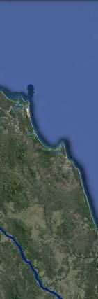
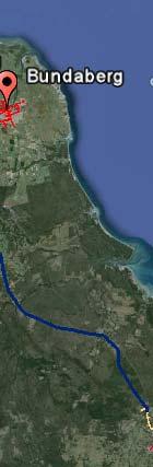
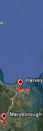
1 APGA Paper Date: 29 August 2015 Subject: Risk Mitigation for Trench Pipeline Under Shallow River Crossings Prepared by: Derek Boo Manager Planning and Engineering Company: APA Group Background: Beginning in December 2012, a series of flood hit Queensland with at least 90 towns and over 900,000 people affected. The Bundaberg region encountered significant flooding as a result of record rainfalls which resulted in the failure of the Wide Bay Pipeline and release of natural gas from under the Burnett River on the 31st January 2013 as shown in Figure 1 below. Flooding from the severe rainfall was thought to have caused scouring of the overlying protective material at the northern banks of the Burnett River. The root cause of the damage was suspected to be caused by the impact from debris carried by the fast flowing water after the pipeline was exposed. Figure 1 Failure of Wide Bay Pipeline in the Burnett River The Wide Bay Pipeline was constructed in 1999/2000 and covers a distance of 275km from Gladstone to Maryborough. The pipeline has four major waterways crossings including (from North to South) the Calliope River, the Boyne River, the Kolan River and the Burnett River. The pipeline also crosses over 20 minor waterways, such as small rivers and creeks (both permanent and intermittent). Documentation from the pipeline construction indicated that the pipeline depth of cover was 2.0m for major waterway crossings and at least 1.2m for minor waterway crossings. The location of the Calliope River, Kolan River, Boyne River and Burnett River crossings are shown in Figure 3 below. The strategy for inspection was to complete a brief inspection of all waterway crossings immediately after the floods with more detailed inspections to follow. Vehicular pipeline patrols were the first form of inspection undertaken and identified a major land slip on the northern bank of Kolan River as shown in Figure 2 below. Detailed inspections of waterway crossings were then conducted using hand held pipe locators and depth probes. The results of these investigations indicated that potential shallow pipe was present at Kolan River, Calliope River


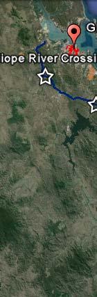
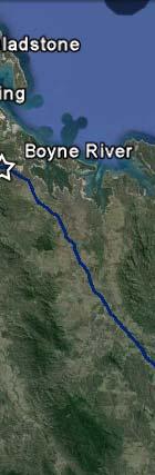
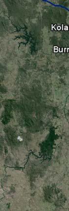
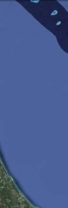
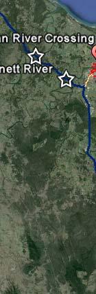


2 and Boyne River as well as a number of minor waterway crossings. Due to the limitations of the pipe locator equipment, it was not possible to determine the exact depth of cover for the pipeline under these riverbeds. Figure 2 Major land slip on the northern banks of the Kolan River (bottom of picture) Figure 3 Locations of Kolan River, Calliope River, Burnett River and Boyne River Crossings
3 Risk Management APA undertook a risk assessment in accordance with the operating Australian Standard for the pipeline (AS 2885) and APA Risk Management Handbook in order to analyse the waterway crossing risks in terms of the consequences (Impact) and the likelihood of the risk (probability). The assessment used established evaluation criteria (i.e. Health & Safety, Environmental, Operational Supply, Customers, Reputation, Compliance and Financial) to produce an estimated level of risk and to rank and prioritise the risks. The risk assessment identified that the Kolan River, Calliope River and Boyne River as HIGH risk asset issues. An engineering assessment concluded that a high water flow or flood event could exceed the allowable pipe stress which may cause failure and subsequent loss of supply to the Wide Bay region. Given that a failure of this nature occurred in the Burnett River in 2013, a potential repeat of this scenario was considered to be very plausible. The most significant risk was identified as per below. Risk Impact of debris with the pipeline causing full bore rupture Likelihood May occur during high water flow events during wet season (nominally November March) Consequence Loss of supply to the towns of Bundaberg, Maryborough and Harvey Bay until a new pipeline can be constructed across the river Risk Ranking High Hydrographic Survey of Trenched Pipelines in Shallow River Crossing Subsequent to the pipeline patrol and inspection of waterway crossing using hand held pipe locators and depth probes, APA engaged Port of Brisbane Pty Ltd (PBPL) to perform a hydrographic survey for Kolan River, Calliope River and Boyne River in order to determine the exact location and burial depth of the pipeline under these riverbeds. APA had employed a number of different inspection methods which included the following: Bathymetric Survey Method Sub-Bottom Profiling Survey Method Side Scan Survey Method Bathymetric Survey Method Due to the shallow water in the Calliope River, Boyne River and Kolan River crossings, this presented significant challenges for PBPL to undertake the hydrographic survey. PBPL was required to mobilise and launch their small survey vessel (see Figure 3 below) near the Gladstone Power Station at a public boat ramp approximately 12km downstream of the pipeline crossing site. The vessel was then motored upstream, taking extreme care at all times during the travel as river depths were unknown and extremely shallow in places. In order to obtain a complete bathymetric surface of the riverbed, the best technology to use would have been the multibeam sonar system as it has a much wider coverage of the seafloor mapping, a higher resolution and excellent data sample density as compared to a singlebeam sonar system. The multibeam sonar is a common offshore surveying tool that uses multiple sound signals (i.e. 512 single beam transducers) to detect the seafloor. Due to its multiple beams, it is able to map a swath of the river or sea bed under the boat, in contrast to a single beam sonar which only maps a point below the boat. Figure 4 below shows the multibeam sonar footprint below the ship. However, multibeam systems require a larger vessel than single-beam systems, which meant that this was not possible in the shallow water at these crossings.

4 Figure 3 PBPL Survey Vessel Figure 4 Multibeam Sonar Survey PBPL proposed to use a high resolution dual frequency Singlebeam Sonar System to determine the depth of water and delineate the river bed. The Singlebeam Sonar System, like the Multibeam Sonar System relied on sound signals to detect the seafloor. In Singlebeam Sonar Systems, an acoustic pulse is emitted from a transducer and propagated in a single, narrow cone of energy directed downward towards the sea floor. This provides a single depth measurement for a location directly beneath the ship. The transducer then listens for the reflected energy signal from the sea floor. Water depth is calculated by using the travel time of the emitted pulse as shown in Figure 5 below.
 relevant at the site.")

5 Figure 5 Schematic of Singlebeam Survey Multiple survey lines were run parallel to the river bank at close line spacing of 3-5 m to maximise coverage, working from the deeper waters of the river reach into the shallows of the bank. The soundings were reduced to Australian Height Datum (AHD) relevant at the site. Singlebeam Survey technology is well established and data processing is relatively straight forward. The result for the Singlebeam Survey of Calliope River is shown in Figure 6 below. The PBPL hydrographic team utilised Leicas Smartnet GPS network for high accuracy positional control. The Smartnet system provided GPS RTK (Real-time Kinematic) accuracy corrections to the Rover Receiver aboard the vessel. Using a base station established at the survey site, local survey control points were checked with a GPS Rover Station to check the integrity of the GPS positioning within the survey area before survey work commenced. Figure 6 Singlebeam Survey for Calliope River

6 Sub-Bottom Profiling Survey Method In order to be able to accurately determine the depth of cover of the pipeline below the riverbed, PBPL had utilised a Sub-bottom Profiler equipment with dual transducers to obtain sub-bottom profile data. Sub-bottom Profilers are typically used for buried pipeline surveys because they allow penetration of the substrate and generally produce a good reflector off the pipeline. Sub-bottom Profilers work on the same principle as Singlebeam Sonar System, but use much lower frequency acoustic energy. The acoustic pulses penetrate below the seabed and into the sediment. Returning echoes from sub-bottom features such the buried pipeline are recorded by an array of hydrophones (usually towed further behind the vessel) or by a transducer (mounted to the hull) and creates a trace in the digital record. This is shown in Figure 7 below. PBPL had previously utilised this technology to successfully locate and chart the Murarrie Pipeline crossing under the Brisbane River in However, due to the shallow waters in the Calliope, Kolan and Boyne rivers, the amount of acoustic power produced by the Sub-bottom Profiler, that is needed to penetrate the riverbed, caused acoustic noise interference in the shallower waters, which made it very difficult to accurately detect sub-bottom features. APA worked collaboratively with PBPL to develop a suitable method for undertaking Sub-bottom Survey in the shallow river crossings. Significant work was undertaken by PBPL to test this technology for use in shallow rivers, requiring consultation with international expertise. Subsequent to design and testing, PBPL proposed to use the Innomar SES-2000 (a specialist shallow water Sub-bottom Profiler System) used in conjunction with dual TR-109 transducers set to the lowest settings (i.e. at 3.5 khz with a 30 Beam width) and incorporating FM wide bandwidth signal processing (CHIRP) to provide high ground penetration and a higher resolution for sub-bottom profiling. The transducer was mounted on a pole over the bow of the dinghy, with the GNSS antenna located on the other end of the pole directly above the Sub-bottom Profiler transducer. The interpretation of a sub-bottom profile is very difficult and the extensive data collected across the width of the river was sent to a Geophysicist consultant for further interpretation and analysis. Figure 7 Sub-bottom Profiling Survey The Sub-bottom Profiler records showed acoustic penetration of around 2-3 m towards the centre of the river and less along the river banks due to surface multiples and diffractions from the bank. For the Calliope River pipeline, a few survey lines exhibited what appeared to be a faint parabolic reflector (which marks the top of the pipeline) suggesting either shielding / protection around the pipe or a density of the surrounding sediments similar to the pipeline. The survey showed that the pipeline was only was buried to a range of cm of protective cover. This is shown in Figure 8 below as a semi-transparent unit overlying the more reflective river bottom suggesting that the overlying unit to be unconsolidated silt/mud.

7 Figure 8 Sub-bottom Profile Showing Pipeline Parabolic Reflector It should be noted that there were some limitations with the sub-bottom profiler. Although the Sub-bottom Profiler System was successful in mapping the pipeline location and depth of burial across the Calliope River, detection had failed for the Boyne River survey. No clear parabolic reflector marking the top of the pipe was visible on any of the survey lines. The problems detecting the parabolic reflector could be related to the river substrate, the presence of biogenic gas masking the acoustic signal, the shallow survey depths (and associated multiples) and the material covering or protecting the pipeline. Figure 9 Singlebeam and Sub-bottom Profiler Survey Results for Calliope River Side Scan Survey Method On receipt of the Sub-bottom Survey results, it became apparent that certain sections of the pipeline under the Calliope River could be spanning above the river bed in places. This is shown in Figure 9 above which shows the combination of the singlebeam and sub-bottom profiler survey results whereby the pipeline is shown to be spanning in two locations on either side of the Calliope River. This result was however not conclusive as the resultant power generated by the Sub-bottom Profiler was not suited to pipeline detection above the surface and only measured the change of riverbed densities. To provide confirmation, PBPL decided to return to the site with additional equipment to confirm the potential spans. A high resolution Side Scan Sonar System was used to gather seabed imagery which would enhance and confirm if the pipeline was indeed on the surface of the river bed and spanning in places.

8 Side-scan Survey uses a sonar device that emits conical or fan-shaped pulses down towards the riverbed across a wide angle perpendicular to the direction of travel of the sensor through the water, which may be towed by a vessel as shown in Figure 10 below, or mounted on the ship's hull. As the pulse of sound emitted by the transducers interacts with the riverbed, most of the energy is reflected away from the transducer. The acoustic backscatter that is reflected back to the transducer is recorded in a series of cross-track slices. When stitched together along the direction of motion, these slices form an acoustic image of the riverbed bottom within the swath (i.e. coverage width) of the beam. Figure 10 Side Scan Survey Excellent imagery was collected and the Side Scan image shown on Figure 11 below showed that the pipeline was definitely spanning in two locations on either side of the river. The dark lines in the images are the shadows cast on the riverbed of the pipeline in relation to the location of the towed fish Side Scan Sonar. The bright lines are the ensonification of the pipeline by the Side Scan. Figure 11 Side Scan Image East and West Sides of the Calliope River
9 Divers Inspection Method In order to further verify that the pipeline was exposed and potentially spanning above the riverbed in certain sections, APA engaged Moreton Diving and Marine Contracting to undertake an underwater visual inspection of the pipeline crossing as well as to examinee the exposed section of the pipelinee to determine if there was any damage. APA worked collaboratively with the diving crew in order to develop a Safe Working Method Statement for undertaking the inspection safely. For Calliope River crossing, the divers were able to confirm that on the western bank, the pipeline was exposed and was suspended approximately 10cm above the riverbed for approximately 20m. On the Eastern bank, the divers were able to confirm that the pipeline was suspended around 40cm to 50cm above the river bed for approximately 35m before burying itself into the muddy riverbed. The report from the dive team advised that that scaly growth with some barnacle growth was observed on the pipeline, indicating that the pipeline had been in this situation for a period of time, possibly well before the 2013 flood event. Remediation Techniques APA investigated numerous permanent and temporary repair options including the following: Kolan River bank stabilisation Installation of temporary geofabric sandbags in the riverr over the pipeline for protection. Replacement of the river crossing by horizontal directional drilling (HDD) Kolan River Bank Stabilisation APA engaged Civil Support to develop design and specifications for stabilising the riverr bank at Kolan River where the major bank slip had occurred. The repair involved excavating the material in the slip zone to remove debris, shaping the slip zone and the construction of a toe wall using bulk bags filled with stabilised sand in orderr to stabilise the toe of the slip face as shown in Figure 12 below. Rock and earth fill over geotextile lining was then used to reinstate the bank profile as shown in Figure 13. Figure 12 Boulder Toe Wall Construction at the Kolan River Slip Face


10 Figure 13 Rock and Earth Fill for Reinstating Bank Profile Temporary Geofabric Sandbagging Protection Civil Support was engaged by APA to develop a suitable temporary protection for Kolan River crossing in order to mitigate the risk of further scouring of the riverbed during the wet season and before the pipeline could be permanently replaced. Civil support had proposed the use of custom made 8m by 1.5m Geofabric sandbags with overlay flaps to be placed over the pipeline as shown in Figure 14 below. Each empty bag was first placed in position over the pipeline and a Dredge Pump used to pump wet sand into the bag. Subsequent bags were then place over the previous bag s flap and the process repeated in order to better securee the sand bags in position. Unfortunately, the Geofabric sandbags only had a recommended life span of 2 to 3 years and hencee would need to be replaced repeatedly over the years. Figure 14 Temporary Geofabric Sandbags Protection
11 Replacement of Pipeline by HDD Methods APA evaluated a number of repair methods and decided that replacement of the pipeline crossing via Horizontal Directional Drilling (HDD) at both Kolan River and Calliope River to be the most suitable method for permanent repair, and which would lower the risk for these crossings to an acceptable level. For Kolan River, the HDD pipeline was around 600m long and was installed to a minimum depth of 10m below the riverbed. Stinging and welding of the pipeline was performed on pipelinee roller supports as shown in Figure 15 below and scaffolding support where required as shown in Figure 16 below. Figure 15 Pipeline Roller Supports for Stringing and Welding of the Pipeline Figure 16 Scaffolding & Pipeline Roller Supports for Stringing and Welding of the Pipeline
12 Summary There are significant risk and impact for trench pipelines installed under creeks and rivers due to scouring of the overlying protective material in the riverbed and embankment caused by flood events and resulting in the pipeline becoming exposed. Hydrographic survey has been proven to be a cost effective non-intrusion technique which can be used to proactively assess and managed risk for trenched pipeline asset in shallow waterway crossings. The surveys included a Singlebeam Bathymetric Survey, a Sub-bottom Profiler Survey and a Side Scan Survey. The Sub-bottom Profiler Survey was used as the primary geophysical tool in order to accurately locate and determine the depth of protective cover for the pipeline under the riverbed. The surveys had identified that for the Calliope River; the pipeline was exposed on the river bed and in certain sections was spanning above the riverbed. A number of temporary and permanent repair methods had been utilised by APA for mitigating the risk. This included bank stabilisation works at Kolan River as well as temporary protection of the pipeline by using geofabric sandbags. Other repair options such as reinstalling the pipeline crossing in a trench dredged in the river and reinstating permanent cover over the pipeline had also been explored but was not considered viable due to the levels of rock found in the river and the likely cost and environmental impacts. Therefore, the most robust and viable long term repair solution was to replace the entire river crossing using horizontal directional drilling method. This method would provide the greatest long term certainty over the integrity of the pipeline, with the lowest level of project risk throughout the design and construction phases. APA was thus able to use a number of hydrographic survey technology and methods to proactively assess and manage its risk for waterway crossings.
Advantages of Using Combined Bathymetry and Side Scan Data in Survey Processing T.M. Hiller, L.N. Brisson
 Advantages of Using Combined Bathymetry and Side Scan Data in Survey Processing T.M. Hiller, L.N. Brisson EdgeTech, West WareHam MA, USA EdgeTech 6205 Combined Bathymetric and Side Scan Sonar EdgeTech
from ocean to cloud PARAMETRIC SUB-BOTTOM PROFILER, A NEW APPROACH FOR AN OLD PROBLEM
 PARAMETRIC SUB-BOTTOM PROFILER, A NEW APPROACH FOR AN OLD PROBLEM Geoff Holland, Alcatel-Lucent Submarine Networks Geoff.holland@alcatel-lucent.com Alcatel-Lucent Submarine Networks Ltd, Christchurch Way,
Certified Professionals in Hydrographic Solutions
 Certified Professionals in Hydrographic Solutions Client Satisfaction is our Deliverable Port of Brisbane Pty Ltd Port Surveys Certified Professionals in Hydrographic Surveying Tel +61 (0) 7 3258 4820
High Definition Laser Scanning (HDS) Underwater Acoustic Imaging and Profiling
 Underwater Acoustic Imaging and Profiling") High Definition Laser Scanning (HDS) Underwater Acoustic Imaging and Profiling Images at Depth: The Use of Acoustic Imaging on Large River Crossings A Case Study AGENDA Background of project Review of
High Definition Laser Scanning (HDS) Underwater Acoustic Imaging and Profiling Images at Depth: The Use of Acoustic Imaging on Large River Crossings A Case Study AGENDA Background of project Review of
Utilizing Vessel Based Mobile LiDAR & Bathymetry Survey Techniques for Survey of Four Southern California Breakwaters
 Utilizing Vessel Based Mobile LiDAR & Bathymetry Survey Techniques for Survey of Four Southern California Breakwaters Western Dredging Association: Pacific Chapter September 2012 Insert: Pipe Location
Scottish Hydro Electric Power Distribution Operation, Inspection, Maintenance and Decommissioning Strategy Bute Cumbrae Cable Replacement
 SHEPD Section ID 154 Scottish Hydro Electric Power Distribution Operation, Inspection, Maintenance and Decommissioning Strategy Bute Cumbrae Cable Replacement Contents Definitions and Abbreviations...
14/10/2013' Bathymetric Survey. egm502 seafloor mapping
 egm502 seafloor mapping lecture 10 single-beam echo-sounders Bathymetric Survey Bathymetry is the measurement of water depths - bathymetry is the underwater equivalent of terrestrial topography. A transect
PORTS AUSTRALIA. PRINCIPLES FOR GATHERING AND PROCESSING HYDROGRAPHIC INFORMATION IN AUSTRALIAN PORTS (Version 1.5 November 2012)
") PORTS AUSTRALIA PRINCIPLES FOR GATHERING AND PROCESSING HYDROGRAPHIC INFORMATION IN AUSTRALIAN PORTS (Version 1.5 November 2012) PREFACE These Principles have been prepared by the Hydrographic Surveyors
PORTS AUSTRALIA PRINCIPLES FOR GATHERING AND PROCESSING HYDROGRAPHIC INFORMATION IN AUSTRALIAN PORTS (Version 1.5 November 2012) PREFACE These Principles have been prepared by the Hydrographic Surveyors
Emerging Subsea Networks
 THE FUTURE OF MARINE SURVEY APPLICATIONS FOR SUBMARINE CABLES Ryan Wopschall (Fugro) Email: rwopschall@fugro.com Fugro Pelagos, Inc. - 3574 Ruffin Road, San Diego, California 92123 USA Abstract: New advances
Design and Planning Considerations For a Seabed Survey
 Design and Planning Considerations For a Seabed Survey Vera Quinlan Hydrographer & Data Processor Seabed Survey Overview Survey Platform - What boat do I use? Survey Area / depth of water / objective &
Hydrographic Surveying at The Port of London
 Hydrographic Surveying at The Port of London John Dillon-Leetch Port and Terminal Technology 2009 14 th October, Antwerp Overview Introduction Surveying the Thames Navigational Charting High Resolution
BOTTOM MAPPING WITH EM1002 /EM300 /TOPAS Calibration of the Simrad EM300 and EM1002 Multibeam Echo Sounders in the Langryggene calibration area.
 BOTTOM MAPPING WITH EM1002 /EM300 /TOPAS Calibration of the Simrad EM300 and EM1002 Multibeam Echo Sounders in the Langryggene calibration area. by Igor Kazantsev Haflidi Haflidason Asgeir Steinsland Introduction
Release Performance Notes TN WBMS _R _Release_Presentation.pptx 22 September, 2014
 TN-140079-1.2 WBMS _R2014-06_Release_Presentation.pptx 22 September, 2014 Since the 2013-12 release, NORBIT has made tremendous improvements to both the functionality and performance of the WBMS systems.
Recommended operating guidelines (ROG) for sidescan Sidescan sonar ROG in wrapper.doc English Number of pages: 9 Summary:
 for sidescan Sidescan sonar ROG in wrapper.doc English Number of pages: 9 Summary:") Title: Author(s): Document owner: Recommended operating guidelines (ROG) for sidescan sonar Dave Long (BGS) Dave Long (BGS) Reviewed by: Janine Guinan (MI) 07/09/07 Workgroup: MESH action: 2.1 Version:
Title: Author(s): Document owner: Recommended operating guidelines (ROG) for sidescan sonar Dave Long (BGS) Dave Long (BGS) Reviewed by: Janine Guinan (MI) 07/09/07 Workgroup: MESH action: 2.1 Version:
Acoustic Pipeline Inspection Mind The Gap
 Acoustic Pipeline Inspection Mind The Gap Mike Liddell Chief Surveyor, Fugro Survey Limited UUVS @ Oceanology 2012 13 th March 2012 Contents Menu Introduction to Pipeline Inspection The Current Toolkit
EXPEDITION ADVENTURE PART 2: HIGHER RESOLUTION RANGE SEISMIC IMAGING TO LOCATE A SUNKEN PIRATE SHIP OFF ILE ST MARIE.
 EXPEDITION ADVENTURE PART 2: HIGHER RESOLUTION RANGE SEISMIC IMAGING TO LOCATE A SUNKEN PIRATE SHIP OFF ILE ST MARIE. Jakob B.U. Haldorsen, and Douglas E. Miller, Schlumberger-Doll Research, Ridgefield,
ENVIRONMENT AGENCY GREAT OUSE AND 100 FT DRAIN QUARTERLY BATHYMETRIC SURVEY DECEMBER 2013 SITE SURVEY REPORT NO. H6787
 ENVIRONMENT AGENCY GREAT OUSE AND 100FT DRAIN QUARTERLY BATHYMETRIC SURVEY DECEMBER 2013 NO. H6787 LONGDIN & BROWNING (SURVEYS) LIMITED CHERRY TREE HOUSE CARMARTHEN ROAD SWANSEA SA1 1HE H6787 1 Measured
RAMSTM. 360 Riser and Anchor-Chain Integrity Monitoring for FPSOs
 RAMS 360 Riser and Anchor-Chain Integrity Monitoring for FPSOs Introduction to RAMS Tritech s RAMS is a 360 anchor-chain and riser integrity monitoring system for Floating Production Storage and Offloading
Vieques Underwater Demonstration Project
 Vieques Underwater Demonstration Project NOAA Office of Response and Restoration National Ocean Service 2006-2007 2007 University of New Hampshire Joint Hydrographic Center 2006 Science Application International
An Integrated Marine Gradiometer Array System (MGA)
") An Integrated Marine Gradiometer Array System (MGA) For Detection and Location of Chemical and Conventional UXO/MEC in Shallow to Deep Marine and Freshwater Environments Introduction Tetra Tech EC, Inc.
An Integrated Marine Gradiometer Array System (MGA) For Detection and Location of Chemical and Conventional UXO/MEC in Shallow to Deep Marine and Freshwater Environments Introduction Tetra Tech EC, Inc.
E4014 Construction Surveying. Hydrographic Surveys
 E4014 Construction Surveying Hydrographic Surveys Charts And Maps Hydrographic Chart an information medium and a tool for maritime traffic for the safety and ease of navigation contains information on
HOW TO BEST USE YOUR ELECTRONICS: CHARTING, SONAR, AND IMAGING. By: Captain Tom Blackburn
 HOW TO BEST USE YOUR ELECTRONICS: CHARTING, SONAR, AND IMAGING By: Captain Tom Blackburn Topics I. INTRODUCTION II. CHARTING A TREMENDOUS FISH FINDING TOOL III. CHARTING - SIGNIFICANT CHARTING AND NAVIGATIONAL
Angela Lane, Lowe Environmental Impact / Karen Akuhata (WDC) The Wairoa wastewater treatment system requires a replacement consent by May 2019.
 The Wairoa wastewater treatment system requires a replacement consent by May 2019.") MEMORANDUM Job No.10292 To: From: Jamie Cox, Wairoa District Council Angela Lane, Lowe Environmental Impact / Karen Akuhata (WDC) Date: 11 September 2017 Subject: Task A2I2 Current Outfall Pipe Description
MEMORANDUM Job No.10292 To: From: Jamie Cox, Wairoa District Council Angela Lane, Lowe Environmental Impact / Karen Akuhata (WDC) Date: 11 September 2017 Subject: Task A2I2 Current Outfall Pipe Description
Hydrographic Surveying Methods, Applications and Uses
 Definition: Hydrographic Surveying Methods, Applications and Uses It is the branch of surveying which deals with any body of still or running water such as a lake, harbor, stream or river. Hydrographic
The Use of Ultrasonic Inspections at Elevated Temperature
 18th World Conference on Nondestructive Testing, 16-20 April 2012, Durban, South Africa The Use of Ultrasonic Inspections at Elevated Temperature Alex McLAY, Jan VERKOOIJEN, TÜV Rheinland Sonovation 4906AZ
OTC MS. Free Span Rectification by Pipeline Lowering (PL) Method N. I. Thusyanthan, K. Sivanesan & G. Murphy
 Method N. I. Thusyanthan, K. Sivanesan & G. Murphy") OTC-24699-MS Free Span Rectification by Pipeline Lowering (PL) Method N. I. Thusyanthan, K. Sivanesan & G. Murphy Copyright 2014, Offshore Technology Conference This paper was prepared for presentation
OTC-24699-MS Free Span Rectification by Pipeline Lowering (PL) Method N. I. Thusyanthan, K. Sivanesan & G. Murphy Copyright 2014, Offshore Technology Conference This paper was prepared for presentation
INTERNATIONAL HYDROGRAPHIC SURVEY STANDARDS
 INTERNATIONAL HYDROGRAPHIC SURVEY STANDARDS by Gerald B. MILLS 1 I. Background The International Hydrographic Organization (IHO) traces its origin to the establishment of the International Hydrographic
A NEW APPROACH TO BUCKLING DETECTION IN OFFSHORE PIPELINE LAYING
 A NEW APPROACH TO BUCKLING DETECTION IN OFFSHORE PIPELINE LAYING By Marian Copilet, Durham Pipeline Technology Ltd., Gateshead, UK & Prof. Ernie Appleton, University of Durham 1. ABSTRACT This paper discusses
REMR TECHNICAL NOTECO-SE-1,4 SIDE SCAN SONAR FOR INSPECTION OF COASTAL STRUCTURES. Suppl 3
 REMR TECHNICAL NOTECO-SE-1,4 SIDE SCAN SONAR FOR INSPECTION OF COASTAL STRUCTURES PURPOSE : To provide information on operating rules-of-thumb, and suggestions on Side Scan Sonar (SSS) uses in coastal
EPA R6 Dive Team Operations Report. San Jacinto Waste Pits Channelview, TX December 9-10, 2015
 EPA R6 Dive Team Operations Report San Jacinto Waste Pits Channelview, TX December 9-10, 2015 BACKGROUND The San Jacinto River Waste Pit Site history has been documented in several documents prepared for,
BEFORE THE ENVIRONMENTAL PROTECTION AUTHORITY JOINT STATEMENT OF EXPERTS IN THE FIELD OF MARINE MAMMALS
 BEFORE THE ENVIRONMENTAL PROTECTION AUTHORITY IN THE MATTER of the Exclusive Economic Zone and Continental Shelf (Environmental Effects) Act 2012 AND IN THE MATTER of an Application for Marine D u m p
Background Paper: Surveys. Nord Stream 2 AG Sep-17
 Nord Stream 2 AG Sep-17 Table of Contents Introduction... 3 Advanced Technology... 4 Survey Stages... 4 2 Introduction Survey operations are the cornerstone of massive international infrastructure projects
The optimal position of a sidescan sonar towfish fixed to a shellfish vessel for very shallow surveys an experiment in the Dutch Wadden Sea
 Title: Author(s): Document owner: The optimal position of a sidescan sonar towfish fixed to a shellfish vessel for very shallow surveys an experiment in the Dutch Wadden Sea Ronnie van Overmeeren (TNO)
Meeting the Challenges of the IHO and LINZ Special Order Object Detection Requirements
 Meeting the Challenges of the IHO and LINZ Special Order Object Detection Requirements Erik Hammerstad Kongsberg Maritime P. O. Box 111, N-3191 Horten, Norway erik.oscar.hammerstad@kongsberg.com Abstract
High Frequency Acoustical Propagation and Scattering in Coastal Waters
 High Frequency Acoustical Propagation and Scattering in Coastal Waters David M. Farmer Graduate School of Oceanography (educational) University of Rhode Island Narragansett, RI 02882 phone: (401) 874-6222
CHALLENGES IN UXO-DETECTION: COMBINING DIFFERENT GEOPHYSICAL TECHNIQUES WITHIN UXO INVESTIGATION & CLEARANCE
 PRESENTATION HYDRO 17 15/11/2017 CHALLENGES IN UXO-DETECTION: COMBINING DIFFERENT GEOPHYSICAL TECHNIQUES WITHIN UXO INVESTIGATION & CLEARANCE Jana De Cuyper - MSc Geology Conor Davidge - BSc Ocean Exploration
Data Collection and Processing: Elwha Estuary Survey, February 2013
 Data Collection and Processing: Elwha Estuary Survey, February 2013 Ian Miller, WA Sea Grant Olympic Peninsula Field Office, 1502 E. Lauridsen Blvd #82, Port Angeles, WA 98362 immiller@u.washington.edu
2012 INDUSTRY DAY Society of American Military Engineers - Omaha Post
 2012 INDUSTRY DAY Society of American Military Engineers - Omaha Post Omaha District Corps of Engineers Military Munitions Design Center (MMDC) Glenn Marks MMDC Manager May 8, 2012 US Army Corps of Engineers
TECHNICAL MEMORANDUM 002 EMORANNO. 001
 TECHNICAL MEMORANDUM 002 EMORANNO. 001 To: Jack Synder, P.E. EES Consulting From: Mort McMillen, P.E. Paul Larson, SE Date: October 13, 2010 Project: Cc: Taylor Bowen Subject: Technical Memorandum (TM)
UNDERWATER SCIENCE. Multibeam Systems TECHNOLOGY FOR SUSTAINABLE FISHERIES
 UNDERWATER SCIENCE Multibeam Systems TECHNOLOGY FOR SUSTAINABLE FISHERIES SIMRAD ME70 SCIENTIFIC MULTIBEAM ECHO SOUNDER A scientific multibeam echo sounder can be seen as many EK sounders spread out in
Multibeam and Laser: Combined High Resolution. Hydrographic Surveying for Civil Engineering Project Support
 Multibeam and Laser: Combined High Resolution Hydrographic Surveying for Civil Engineering Project Support John Dillon-Leetch,Port of London Authority Duncan Mallace, NetSurvey, UK Overview Introduction
Geospatial Positioning Accuracy Standards Part 5: Standards for Nautical Charting Hydrographic Surveys - Public Review Draft
 Appendix B FGDC Hydrographic Accuracy Standard Geospatial Positioning Accuracy Standards Part 5: Standards for Nautical Charting Hydrographic Surveys - Public Review Draft Subcommittee on Marine and Coastal
UXO Below: Mitigating Marine UXO Risk
 RPS Energy Ltd Explosives Engineering Services UXO Below: Mitigating Marine UXO Risk Presented by Victoria Phillips 1 Aim To deliver an overview of Unexploded Ordnance (UXO) in the marine environment,
NEED FOR SUPPLEMENTAL BATHYMETRIC SURVEY DATA COLLECTION
 305 West Grand Avenue, Suite 300 Montvale, New Jersey 07645 Phone 201.930.9890 Fax 201.930.9805 www.anchorqea.com M EMORANDUM To: Caroline Kwan and Nica Klaber U.S. Environmental Protection Agency Region
Robin J. Beaman. School of Earth and Environmental Sciences, James Cook University, Cairns, Qld 4870, Australia.
 Robin J. Beaman School of Earth and Environmental Sciences, James Cook University, Cairns, Qld 4870, Australia. Email: robin.beaman@jcu.edu.au Seminar to SSSI Qld Hydrography Coping with Nature, Brisbane,
NOAA s Underwater UXO Demonstration Projects Vieques Island, Puerto Rico
 NOAA s Underwater UXO Demonstration Projects Vieques Island, Puerto Rico Vieques Restoration Advisory Board Meeting May 7, 2008 Jason Rolfe NOAA s Office of Response & Restoration NOAA s Underwater UXO
LiDAR My favourite tool in the bag 2011 St Kitts & Nevis
 LiDAR My favourite tool in the bag 2011 St Kitts & Nevis Lt Cdr Rupert Forester-Bennett RN (ret d) December 5 th to 11 th 2011 Content Collection of geospatial data reasons Overcoming the White Ribbon
H ydrog ra p h ic S urve y Using SEABAT
 H ydrog ra p h ic S urve y Using SEABAT Hirokazu Mori, Tadashi Yamamoto and Isao Tedokon, Hydrographic Department, Japan Coast Guard The original was written in 1999, and our hydrographic surveys using
The optimal position of a sidescan sonar towfish fixed to a shellfish vessel for very shallow surveys an experiment in the Dutch Wadden Sea
 TNO report 2006-U-RO114/A The optimal position of a sidescan sonar towfish fixed to a shellfish vessel for very shallow surveys an experiment in the Dutch Wadden Sea NITG/Geological Survey Princetonlaan
PROPOSING A NEW PORTABLE DEVICE FOR BRIDGE SCOUR INSPECTION
 PROPOSING A NEW PORTABLE DEVICE FOR BRIDGE SCOUR INSPECTION KISEOK KWAK Senior Researcher, Geotech. Eng. Res. Dept., Korea Institute of Construction Technology, 2311 Daehwa-dong, Ilsan-gu, Koyang City,
Sonar Bathymetry: Waquoit Bay NERR
 Sonar Bathymetry: Waquoit Bay NERR Determining the Functional Shallow Water Limitation for an Arrival Based Sonar Frederick A. Hegg Teledyne Benthos, Inc. 49 Edgerton Drive North Falmouth, MA 02556 fhegg@teledyne.com
Potential applications of AUVs and Gliders in Offshore Windfarm Site Surveys
 Potential applications of AUVs and Gliders in Offshore Windfarm Site Surveys Dr James Hunt (National Oceanography Centre, Southampton) MREKE Internship in partnership with MARS at NOCS Introduction to
Malta Survey activities
 Malta Survey activities Malta 19 September 2016 L. Facchin OGS National Institute of Oceanography and Experimental Geophysics Offshore Multibeam (MBES) Sub bottom profiling (SBP: Chirp or Boomer) Multichannel
UTEC Survey Pipeline Inspection Using Low Logistic AUV June 2016
 SUCCESS YOU CAN MEASURE UTEC Survey Pipeline Inspection Using Low Logistic AUV June 2016 Chris Erni Product Line Manager E T H I C S P E R F O R M A N C E E X C E L L E N C E P E O P L E GLOBAL FOOTPRINT
Low Gradient Velocity Control Short Term Steep Gradient Channel Lining Medium-Long Term Outlet Control Soil Treatment Permanent [1]
![Low Gradient Velocity Control Short Term Steep Gradient Channel Lining Medium-Long Term Outlet Control Soil Treatment Permanent [1]](/thumbs/80/80811988.jpg "Low Gradient Velocity Control Short Term Steep Gradient Channel Lining Medium-Long Term Outlet Control Soil Treatment Permanent [1]") Check Dams DRAINAGE CONTROL TECHNIQUE Low Gradient Velocity Control Short Term Steep Gradient Channel Lining Medium-Long Term Outlet Control Soil Treatment Permanent [1] [1] Though not generally considered
Check Dams DRAINAGE CONTROL TECHNIQUE Low Gradient Velocity Control Short Term Steep Gradient Channel Lining Medium-Long Term Outlet Control Soil Treatment Permanent [1] [1] Though not generally considered
Qualark Creek. Split-beam system. History. Using split-beam technology. Single beam system (fish finder) What is a Sonar (Hydroacoustic) system?
 What is a Sonar (Hydroacoustic) system?") Single beam system (fish finder) Qualark Creek Not particularly good for counting fish! How far away YES! How big.no! Which way it s going..no! Dept. Fisheries & Oceans Canada Applied Technologies George
Single beam system (fish finder) Qualark Creek Not particularly good for counting fish! How far away YES! How big.no! Which way it s going..no! Dept. Fisheries & Oceans Canada Applied Technologies George
Welsh Waters Scallop Strategy 28 th May Summary of research
 Welsh Waters Scallop Strategy 28 th May 2013 Summary of research Introduction This document describes the scallop research being conducted by Bangor University s Fisheries & Conservation Science Group
Body Search and Recovery Using Sonar
 Body Search and Recovery Using Sonar Photos Mark W. Atherton Mark W. Atherton, Echoes and Images Image courtesy FBI Dive Team Images not for distribution. All photographs and drawings courtesy and Mark
Survey solutions. catalogue DEEP INSIGHT. SHARPER SENSES.
 Survey solutions catalogue DEEP INSIGHT. SHARPER SENSES. i stands for Imagination. «X» is the excellence for which we strive. Our technologies guarantee superiority in all senses - navigating from the
Survey of Underwater NDT Technologies for Offshore Assets
 Survey of Underwater NDT Technologies for Offshore Assets Ayman Amer, Fadl Abdellatif, Ali Outa, Hassane Trigui, Sahejad Patel, Ameen Obedan, Fernando Diaz Ledezma, Hamad Al Saiari and Ihsan Taie, Saudi
IFREMER, Department of Underwater Systems, Toulon, France. L u c i e Somaglino, P a t r i c k J a u s s a u d, R o main P i a s co, E w e n Raugel
 F i r s t s e a t r i a l s w i t h E M 2 0 4 0 m u l t i b e a m s o u n d e r i n n o v a t i v e i n t e g r a t i o n o n H y b r i d R O V A r i a n e IFREMER, Department of Underwater Systems, Toulon,
State of the Art Mapping of Portland Harbour - August 2004
 State of the Art Mapping of Portland Harbour - August 2004 In 2003 and 2004, as part of the "Diving with a Purpose" initiative the Nautical Archaeology Society mapped some of the wrecks in and around Portland
NEW SURVEY MOTOR LAUNCHES FOR THE ROYAL AUSTRALIAN NAVY
 International Hydrographic Review, Monaco, LXVI(l), January 1989 NEW SURVEY MOTOR LAUNCHES FOR THE ROYAL AUSTRALIAN NAVY by Commander John LEECH, RAN (*) INTRODUCTION By any standards the task facing the
Using Sonar for Navigation
 Using Sonar for Navigation By Steve Dashew We spend a lot of time cruising in remote areas, where charts tend to be out-of-date or nonexistent. For years we've been thinking about using sonar for navigation
COUPLED MANAGEMENT STRATEGY LAKE CATHIE ESTUARY & COAST
 Lake Cathie Progress Association Inc. ABN 28 251 433 854 P.O. Box 247 Lake Cathie NSW 2445 PHONE/FAX: 02 6584 8211 EMAIL: r3packag@bigpond.com 20 th October 2009 Port Macquarie Hastings Council PO Box
Specifications for Synchronized Sensor Pipe Condition Assessment (AS PROVIDED BY REDZONE ROBOTICS)
") Specifications for Synchronized Sensor Pipe Condition Assessment (AS PROVIDED BY REDZONE ROBOTICS) A. Scope of Work The work covered by these specifications consists of furnishing all materials, labor,
Specifications for Synchronized Sensor Pipe Condition Assessment (AS PROVIDED BY REDZONE ROBOTICS) A. Scope of Work The work covered by these specifications consists of furnishing all materials, labor,
WG Marine Intruder Detection Sonar
 fire safety security defence The Westminster Marine Intruder Detection Sonar (WG MIDS) system is a single- or multi-head active sonar system designed to automatically detect and track underwater and surface
The Challenge of Underwater Gas (Leakage) Monitoring
 Monitoring") The Challenge of Underwater Gas (Leakage) Monitoring Ingo Möller Kai Spickenbom, Volker Böder, Martin Krüger IEAGHG workshop on Natural Releases of CO2, Maria Laach, November 2 4, 2010 Challenges of underwater
The Challenge of Underwater Gas (Leakage) Monitoring Ingo Möller Kai Spickenbom, Volker Böder, Martin Krüger IEAGHG workshop on Natural Releases of CO2, Maria Laach, November 2 4, 2010 Challenges of underwater
Learn more at
 Full scale model tests of a steel catenary riser C. Bridge 1, H. Howells 1, N. Toy 2, G. Parke 2, R. Woods 2 1 2H Offshore Engineering Ltd, Woking, Surrey, UK 2 School of Engineering, University of Surrey,
MARINE NAVIGATION LESSON PLAN See That Sound?
 Marine Navigation Hydrography Lesson Plan MARINE NAVIGATION LESSON PLAN See That Sound? Theme Hydrographic Survey Links to Overview Essays and Resources Needed for Student Research http://oceanservice.noaa.gov/topics/navops/hydrosurvey/
Risks Associated with Caissons on Ageing Offshore Facilities
 Risks Associated with Caissons on Ageing Offshore Facilities D. Michael Johnson, DNV GL, Peter Joyce, BG Group, Sumeet Pabby, BG Group, Innes Lawtie, BG Group. Neil Arthur, BG Group, Paul Murray, DNV GL.
A review of best practices for Selection, Installation, Operation and Maintenance of Gas meters for Flare Applications used for Managing facility
 A review of best practices for Selection, Installation, Operation and Maintenance of Gas meters for Flare Applications used for Managing facility mass balance and compliance 1. What, When and Why? 2. Flare
Advanced PMA Capabilities for MCM
 Advanced PMA Capabilities for MCM Shorten the sensor-to-shooter timeline New sensor technology deployed on off-board underwater systems provides navies with improved imagery and data for the purposes of
Compact Light Weight RC Boat for Hydrographic Surveys on Dams, Creeks, Rivers, storm water retention pits and other waterways.
 Accura Hydrographic RC Survey Boat Compact Light Weight RC Boat for Hydrographic Surveys on Dams, Creeks, Rivers, storm water retention pits and other waterways. Utilises Sounder & Transducer from CEE
S-44 edition 5 The IHO s New Standard For Hydrographic Surveys Chris Howlett Head of Seabed Data Centre United Kingdom Hydrographic Office
 S-44 edition 5 The IHO s New Standard For Hydrographic Surveys Chris Howlett Head of Seabed Data Centre United Kingdom Hydrographic Office Chairman of IHO Working Group that created S-44 edition 5 S-44
UNDERWATER SERVICES COMPANY PROFILE
 UNDERWATER SERVICES COMPANY PROFILE irov Underwater Services is an Italian Independent H i g h l y S p e c i a l i z e d C o m p a n y p r o v i d i n g underwater technology and ROV assistance to Salvage
Charlottetown Marine Terminal Pipeline Decommissioning Project Description
 Charlottetown Marine Terminal Pipeline Decommissioning Project Description 69 Marr Road Unit B Rothesay NB, E2E 3J9 Tel (506) 848-1920 Fax (506) 848-1929 Charlottetown Marine Terminal Pipeline Decommissioning
Noise Experiment #2. Marine Physical Laboratory Scripps Institution of Oceanography La Jolla, CA February 22 February 2010
 Noise Experiment #2 Marine Physical Laboratory Scripps Institution of Oceanography La Jolla, CA 92093-0701 16 February 22 February 2010 1. Objective The objective of the noise experiment is to observe
Implications of proposed Whanganui Port and lower Whanganui River dredging
 PO Box 637 Wanganui 4540 Attention: Rowan McGregor Dear Rowan 1 Summary We understand that it has been proposed to bring large vessels into the Port at Whanganui requiring the excavation of a channel up
OFFSHORE SURVEY IN DEVELOPMENT PROJECTS. Ian Douglas Head, Offshore Surveys, Shell Projects & Technology Europe
 OFFSHORE SURVEY IN DEVELOPMENT PROJECTS Ian Douglas Head, Offshore Surveys, Shell Projects & Technology Europe THE PROJECT: GOLDENEYE GOLDENEYE FACTS ST. FERGUS GOLDENEYE PLATFORM Gas Condensate Field
INTERNATIONAL HYDROGRAPHIC REVIEW MAY 2015
 OPERATION TIRÚA: HYDROGRAPHIC VISION N.A. Guzmán Montesinos Naval Hydrographic Engineer Head of the Information Technology Department Head of the Chilean Tsunami Warning Center, Chile Abstract On 6 October
Survey Technique for Underwater Digital Photography with Integrated GPS Location Data
 Survey Technique for Underwater Digital Photography with Integrated GPS Location Data Tim Siwiec: United States Environmental Protection Agency Abstract This survey technique is an inexpensive method of
CORRELATION BETWEEN SONAR ECHOES AND SEA BOTTOM TOPOGRAPHY
 CORRELATION BETWEEN SONAR ECHOES AND SEA BOTTOM TOPOGRAPHY JON WEGGE Norwegian Defence Research Establishment (FFI), PO Box 115, NO-3191 Horten, Norway E-mail: jon.wegge@ffi.no False alarms resulting from
3 CONSTRUCTION. 3.1 Construction Methods and Sequence. 3.2 Construction Sequence
 3 CONSTRUCTION 3.1 Construction Methods and Sequence The Construction Strategy for the offshore field and pipeline is described in the 2001 Offshore EIS. Some construction activities have taken place since
Excavations and Trenches
 Purpose Excavation and trenching are among the most hazardous work activities undertaken by the TNRD. This document outlines general requirements and specific safe work procedures to ensure the health
Qualark Creek. History
 Qualark Creek Dept. Fisheries & Oceans Canada Applied Technologies George Cronkite, Hermann J Enzenhofer, John Holmes & Jim Krivanek History Originally used split-beam technology (1993-1998) Ideal site
EXPERIMENTAL RESULTS OF GUIDED WAVE TRAVEL TIME TOMOGRAPHY
 18 th World Conference on Non destructive Testing, 16-20 April 2012, Durban, South Africa EXPERIMENTAL RESULTS OF GUIDED WAVE TRAVEL TIME TOMOGRAPHY Arno VOLKER 1 and Hendrik VOS 1 TNO, Stieltjesweg 1,
Large-scale Field Test
 Vaskinn 1 Large-scale Field Test Kjetil Arne Vaskinn kav@trh.statkraftgroner.no Statkraft Grøner AS SUMMARY The objective the controlled failure of large-scale embankment is to monitor and record the failure
CONTRACTOR DOCUMENT FRONT SHEET NOT PROTECTIVELY MARKED H P C - D E V X X R E T
 CONTRACTOR DOCUMENT FRONT SHEET NOT PROTECTIVELY MARKED PROJECT CONTRACT CODE ASSET SYSTEM BUILDING DOCUMENT TYPE DOCUMENT DETAILS SEQUENTIAL NUMBER H P C - D E V 0 2 4 - X X - 0 0 0 - R E T - 1 0 0 0
IMCA DP Station Keeping Bulletin 04/18 November 2018
 DP STATION KEEPING BULLETIN IMCA DP Station Keeping Bulletin 04/18 November 2018 The following event trees have been compiled from recent reports received by IMCA. The originators granted IMCA permission
Advanced Surf Kayak Leader Training Notes
 Advanced Surf Kayak Leader Training Notes Part A Personal Paddling Skills A.1 Lifting, carrying, launching and landing The type of break surfed at this level will mean the application of a large variation
Crew Transfer Vessel (CTV) Performance Benchmarking. Presented by Stephen Phillips of Seaspeed Marine Consulting Ltd
 Performance Benchmarking. Presented by Stephen Phillips of Seaspeed Marine Consulting Ltd") Crew Transfer Vessel (CTV) Performance Benchmarking Presented by Stephen Phillips of Seaspeed Marine Consulting Ltd BACKGROUND - CT OWA : The Carbon Trust Offshore Wind Accelerator (OWA) brings together
Crew Transfer Vessel (CTV) Performance Benchmarking Presented by Stephen Phillips of Seaspeed Marine Consulting Ltd BACKGROUND - CT OWA : The Carbon Trust Offshore Wind Accelerator (OWA) brings together
Examples of Carter Corrected DBDB-V Applied to Acoustic Propagation Modeling
 Naval Research Laboratory Stennis Space Center, MS 39529-5004 NRL/MR/7182--08-9100 Examples of Carter Corrected DBDB-V Applied to Acoustic Propagation Modeling J. Paquin Fabre Acoustic Simulation, Measurements,
Measured broadband reverberation characteristics in Deep Ocean. [E.Mail: ]
![Measured broadband reverberation characteristics in Deep Ocean. [E.Mail: ]](/thumbs/90/101823179.jpg "Measured broadband reverberation characteristics in Deep Ocean. [E.Mail: ]") Measured broadband reverberation characteristics in Deep Ocean Baiju M Nair, M Padmanabham and M P Ajaikumar Naval Physical and Oceanographic Laboratory, Kochi-682 021, India [E.Mail: ] Received ; revised
Measured broadband reverberation characteristics in Deep Ocean Baiju M Nair, M Padmanabham and M P Ajaikumar Naval Physical and Oceanographic Laboratory, Kochi-682 021, India [E.Mail: ] Received ; revised
CODEVINTEC. All the sonars you need, in one place
 45 27 39.384 N 9 07 30.145 E All the sonars you need, in one place Teledyne RESON, BlueView and Odom Hydrographic are part of the Teledyne Marine Acoustic Imaging Group (TMAIG). With more than 35 years
Inspection of CANDU Reactor Pressure Tubes Using Ultrasonics
 17th World Conference on Nondestructive Testing, 25-28 Oct 2008, Shanghai, China Inspection of CANDU Reactor Pressure Tubes Using Ultrasonics Michael TRELINSKI Inspection & Maintenance Services Ontario
HYDROGRAPHIC AND SITE SURVEY REPORT
 HYDROGRAPHIC AND SITE SURVEY REPORT Proposed Pen Site at Dounie, Sound of Jura Prepared for: Kames Fish Farming Ltd Kilmelford Argyll PA34 4XA Tel: +44 (0)1631 720699 TransTech Limited www.transtechltd.com
Tifft Water Supply Symposium
 Tifft Water Supply Symposium SEPTEMBER 21-22, 2016 BUFFALO, NEW YORK Impossible Journey: Underwater Inspection of Large Diameter Water Transmission Tunnel Kristin Wheaton, PE Jim Clark Bob Clarke, P.Eng,
WMB-160F Multi-beam Fishing System
 WMB-160F Multi-beam Fishing System Take away the guess work and see what s REALLY below your boat! Seven Systems in One 2 WMB-160F WMB-160F Screen Shots The WMB-160F is a multi-beam sonar that has been
Click to edit Master title style Advanced Military Layers. and the Historic Environment
 Advanced Military Layers and the Historic Environment Paul Baggaley and Louise Tizzard Wessex Archaeology 1 Click to edit Objectives Master title style to establish the degree of mutual benefit in integrating