KENT COUNTY, DELAWARE AND INCORPORATED AREAS
|
|
|
- Tyler Blair
- 6 years ago
- Views:
Transcription


 100001 LEIPSIC, TOWN OF")

1 This preliminary FIS report only includes revised Floodway Data Tables and revised Flood Profiles. The unrevised components will appear in the final FIS report. KENT COUNTY, DELAWARE AND INCORPORATED AREAS COMMUNITY COMMUNITY NAME NUMBER BOWERS, TOWN OF CAMDEN, TOWN OF CHESWOLD, TOWN OF CLAYTON, TOWN OF DOVER, CITY OF FELTON, TOWN OF FREDERICA, TOWN OF HARRINGTON, CITY OF KENT COUNTY (UNINCORPORATED AREAS) LEIPSIC, TOWN OF LITTLE CREEK, TOWN OF SMYRNA, TOWN OF WOODSIDE, TOWN OF WYOMING, TOWN OF Kent County Federal Emergency Management Agency FLOOD INSURANCE STUDY NUMBER 10001CV000B
2 NOTICE TO FLOOD INSURANCE STUDY USERS Communities participating in the National Flood Insurance Program have established repositories of flood hazard data for floodplain management and flood insurance purposes. This Flood Insurance Study (FIS) may not contain all data available within the repository. It is advisable to contact the community repository for any additional data. Part or all of this FIS may be revised and republished at any time. In addition, part of this FIS may be revised by the Letter of Map Revision process, which does not involve republication or redistribution of the FIS. It is, therefore, the responsibility of the user to consult with community officials and to check the community repository to obtain the most current FIS components. Initial Countywide FIS Effective Date: May 5, 2003 Revised Countywide FIS Dates: This Preliminary FIS report only includes revised floodway Data Tables and revised Flood Profiles. The unrevised components will appear in the final FIS report.
3 TABLE OF CONTENTS 1.0 INTRODUCTION Purpose of Study Authority and Acknowledgments Coordination AREA STUDIED Scope of Study Community Description Principal Flood Problems Flood Protection Measures ENGINEERING METHODS Hydrologic Analyses Hydraulic Analyses Coastal Analysis Vertical Datum FLOODPLAIN MANAGEMENT APPLICATIONS Floodplain Boundaries Floodways INSURANCE APPLICATIONS FLOOD INSURANCE RATE MAP OTHER STUDIES LOCATION OF DATA BIBLIOGRAPHY AND REFERENCES 62 i
4 TABLE OF CONTENTS continued FIGURES Figure 1 Frequency-Discharge, Drainage Area Curves Figure 2 Transect Location Map 37 Figure 3 Transect Schematic 46 Figure 4 Floodway Schematic 59 TABLES Table 1 Initial and Final CCO Meetings 5 Table 2 Flooding Sources Studied by Detailed Methods 6 Table 3 Scope of Revision 6-7 Table 4 Summary of Discharges Table 5 Summary of Stillwater Elevations 23 Table 6 Summary of Discharges, Limited Detailed Streams Table 7 Manning s n Values Table 8 Manning s n Values, Limited Detailed Study Streams 31 Table 9 Summary of Coastal Stillwater Elevations 34 Table 10 Transect Descriptions Table 11 Transect Data Table 12 Floodway Data Table 13 Community Map History 61 EXHIBITS Exhibit 1 - Flood Profiles Andrews Lake Beaverdam Ditch Panels 01P-02P Panel 03P ii
5 TABLE OF CONTENTS continued EXHIBITS-continued Brown s Branch North Brown s Branch South Cahoon Branch Choptank River Tidy Island Creek Coursey Pond Cow Marsh Creek Willow Grove Prong Culbreth Marsh Ditch Duck Creek Providence Creek Fork Branch Green Branch Green's Branch Horsepen Arm Issac Branch Leipsic River Little River Maidstone Branch Penrose Branch Marshyhope Creek Marshyhope Ditch McColley Pond McGinnis Pond Mill Creek Morgan Branch Puncheon Branch St. Jones River Stream No. 1 Tantrough Branch Tappahanna Ditch Tidbury Creek Beaverdam Branch Beaverdam Branch Tributary 1 Panel 04P Panel 05P Panels 06P-10P Panels 11P-14P Panels 14P-16P Panels 17P-18P Panels 19P-25P Panels 25P-26P Panels 27P-29P Panels 30P-33P Panels 33P-34P Panels 35P-39P Panels 40P-43P Panels 44P-45P Panels 46P-48P Panels 49P-50P Panel 51P Panels 52P-54P Panels 55P-58P Panels 58P-61P Panels 62P-67P Panels 67P-69P Panels 70P-71P Panels 72P-73P Panel 74P Panels 75P-76P Panels 77P-78P Panels 79P-84P Panel 85P Panels 86P-88P Panels 89P-93P Panels 94P-97P Panel 98P Panel 99P iii
6 TABLE OF CONTENTS continued Black Swamp Creek Browns Branch Browns Branch Tributary 1 Double Run Fan Branch Hudson Branch Murderkill River Pratt Branch Red House Branch Spring Branch Tidbury Creek Tributary 3 Panels 100P-105P Panels 106P-110P Panels 111P-112P Panels 113P-116P Panels 117P-118P Panels 119P-122P Panels 123P-127P Panels 128P-131P Panel 132P Panels 133P-135P Panel 136P EXHIBITS-continued Exhibit 2 - Flood Insurance Rate Map Index Flood Insurance Rate Map iv
7 FLOOD INSURANCE STUDY KENT COUNTY, DELAWARE AND INCORPORATED AREAS 1.0 INTRODUCTION 1.1 Purpose of Study This Flood Insurance Study (FIS) revises and updates information on the existence and severity of flood hazards in the geographic area of Kent County, Delaware, including: the Cities of Dover and Harrington; and the Towns of Bowers, Camden, Cheswold, Clayton, Felton, Frederica, Leipsic, Little Creek, Smyrna, Woodside, and Wyoming (hereinafter referred to collectively as Kent County); and aids in the administration of the National Flood Insurance Act of 1968 and the Flood Disaster Protection Act of This study has developed flood-risk data for various areas of the community that will be used to establish actuarial flood insurance rates and to assist the community in its efforts to promote sound floodplain management. Minimum floodplain management requirements for participation in the National Flood Insurance Program (NFIP) are set forth in the Code of Federal Regulations at 44 CFR, Please note that the Towns of Clayton and Smyrna are geographically located in Kent and New Castle Counties. The Towns of Clayton and Smyrna are included in their entirety in this FIS report. The City of Milford is geographically located in Kent and Sussex Counties. The City of Milford is shown in its entirety in the FIS report for Sussex County. See the separately published FIS reports and Flood Insurance Rate Maps (FIRMs) for countywide map dates and flood hazard information outside of Kent County. Please note that on the effective date of this study, the Towns of Farmington, Hartley, Houston, Kenton, Magnolia, and Viola have no mapped Special Flood Hazard Areas (SFHAs). This does not preclude future determinations of SFHAs that could be necessitated by changed conditions affecting the community (i.e. annexation of new lands) or the availability of new scientific or technical data about flood hazards. In some States or communities, floodplain management criteria or regulations may exist that are more restrictive or comprehensive than the minimum Federal requirements. In such cases, the more restrictive criteria take precedence and the State (or other jurisdictional agency) will be able to explain them. 1.2 Authority and Acknowledgments The sources of authority for this FIS are the National Flood Insurance Act of 1968 and the Flood Disaster Protection Act of
8 The original May 5, 2003 countywide FIS was prepared to include all jurisdictions within Kent County into a countywide format FIS. Information on the authority and acknowledgments for each jurisdiction with a previously printed FIS report included in the countywide FIS is shown below. Bowers, Town of: Camden, Town of: Clayton, Town of: Dover, City of: Frederica, Town of: Harrington, City of: Kent County, (Unincorporated Areas): The wave heights analysis for the FIS report dated March 2, 1982, were performed by Dewberry & Davis for the Federal Emergency Management Agency (FEMA). That work covered coastal flooding from Delaware Bay. The hydrologic and hydraulic analyses for the FIS report dated March 16, 1981, were prepared by Edward H. Richardson Associates, Inc., for the Federal Insurance Administration (FIA), under contract No. H That work was completed in April The hydrologic and hydraulic analyses for the FIS report dated December 1976 were performed by Greenhorne & O'Mara, Inc., for the FIA, under contract No. H That work, which was completed in May 1976, covered all flooding sources affecting the Town of Clayton. The hydrologic and hydraulic analyses for the FIS report dated March 16, 1982, were prepared by Edward H. Richardson Associates, Inc., for FEMA under Contract No. H That work was completed in April The hydrologic and hydraulic analyses for the FIS report dated July 2, 1980, were prepared by Kidde Consultants, Inc., for the FIA under Contract No. H That work was completed in September The hydrologic and hydraulic analyses for the FIS report dated December 1976, were performed by Greenhorne & O'Mara, Inc., Consulting Engineers, Riverdale, Maryland, for the FIA, under Contract No. H That work was completed in May 1976, covering all flooding sources affecting the City of Harrington. The hydrologic and hydraulic analyses for the FIS report dated May 1976 were performed by Greenhorne & O'Mara, Inc., for the FIA, under Contract No. H That work, which was 2
9 Leipsic, Town of: Little Creek, Town of: Smyrna, Town of: Wyoming, Town of: completed in August 1975, covered all significant flooding sources affecting the unincorporated areas of Kent County, Delaware. The Wave Height Analysis Supplement was added to the study to cover coastal effects from Delaware Bay. The hydrologic and hydraulic analyses for the FIS report dated March 1978, were prepared by the U.S. Soil Conservation Service (SCS), for the FIA under Inter-Agency Agreement No. IAA-H-8-77, Project Order No. 5. That work was completed in July 1977, and covered all significant flooding sources affecting the Town of Leipsic, Delaware. The hydrologic and hydraulic analyses for the FIS report dated July 1978, were prepared by the SCS for the FIA under Inter-Agency Agreement No. IAA-H- 8-77, Project Order No. 5. That work, which was completed in June 1977, covered all significant flooding sources affecting the Town of Little Creek, Delaware. The hydrologic and hydraulic analyses for the FIS report dated December 1976, were prepared by Greenhorne & O'Mara, Inc., for the FIA under Contract No. H That work was completed in May 1976, and covered all flooding sources affecting the Town of Smyrna. The hydrologic and hydraulic analyses for the FIS report dated September 16, 1980, were prepared by Edward H. Richardson Associates, Inc., for the FIA under Contract No. H That work was completed in April The authority and acknowledgements for the Towns of Cheswold, Felton, and Woodside are not available because no FIS reports were published for these communities. There are no previous FISs or FIRMs for the Towns of Farmington, Hartley, Houston, Kenton, Magnolia, and Viola; therefore, the previous authority and acknowledgments for these communities are not included in this FIS. These communities will not appear in the Community Map History Table (Section 6.0). For the May 5, 2003 countywide FIS, the hydrologic and hydraulic analyses for the riverine flooding sources were prepared by the U.S. Army Corps of Engineers (USACE), Philadelphia District, for FEMA, under Inter-Agency Agreement No. 3
10 EMW-97-IA-0140, Project Order No.4. This work was completed in September The coastal analyses for the May 5, 2003 FIS were prepared by the USACE, Philadelphia District, for FEMA, under Inter-Agency Agreement No. EMW-97- IA-0104, Project Order No. 4. The work for this revision was completed in August Dewberry & Davis, LLC, supplemented the work by revising other coastal areas within the unincorporated areas of Kent County. The riverine hydrologic and hydraulic analyses for this revision were performed by URS Corporation, for the Delaware Department of Natural Resources and Environmental Control (DNREC), under Task Order No The coastal analyses for this revision were performed by Risk Assessment Mapping and Planning Partners (RAMPP) under contract No. HSFEHQ-09-D-0369, Task Order HSFE The final FIRM database for this revision was developed by RAMPP under contract No. HSFEHQ-09-D-0369, Task Order HSFE for the coastal floodplain portion and Task Order HSFE for the riverine floodplain portion. This study was completed in August Base map information shown on this FIRM was provided in digital format by Delaware Geospatial Data Exchange. The base map features were compiled at a scale of 1:24,000 from aerial photography dated The coordinate system used for the production of this FIRM is Delaware State Plane (FIPS Zone 0700), with a Lambert Conformal Conic projection, units in feet. Corner coordinates shown on the FIRM are in latitude and longitude referenced to the North American Datum of 1983, GRS80 spheroid. Differences in the datum and spheroid used in the production of FIRMs for adjacent counties may result in slight positional differences in map features at the county boundaries. These differences do not affect the accuracy of the information shown on the FIRM. 1.3 Coordination An initial Consultation Coordination Officer s (CCO) meeting is held typically with representatives of FEMA, the community, and the study contractor to explain the nature and purpose of an FIS, and to identify the streams to be studied by detailed methods. A final CCO meeting is held typically with the same representatives to review the results of the study. The dates of the initial and final CCO meetings held for the incorporated communities within Kent County are shown in Table 1, Initial and Final CCO Meetings. 4
11 TABLE 1 - INITIAL AND FINAL CCO MEETINGS Initial/Intermediate CCO Community Name Meeting(s) Final CCO Meeting(s) Bowers, Town of * * Camden, Town of June and July of 1977 May 8, 1980 Clayton, Town of November 1975 May 26, 1976 Dover, City of July 1977 August 11, 1981 Frederica, Town of Aprill2, 1978 February 13, 1980 Harrington, City of November 1975 May 27, 1976 Kent County (Unincorporated Areas) September 13, 1974 July 1, 1975 Leipsic, Town of August 18, 1976 * Little Creek, Town of August 18, 1976 February 6, 1978 Smyrna, Town of November 1975 May 26, 1976 Wyoming, Town of June and July of 1977 May 8, 1980 *Data not available For the May 5, 2003 countywide FIS, an initial CCO meeting was held July 19, 1996, and was attended by representatives from the Towns of Clayton and Smyrna; and the Cities of Dover and Harrington; Kent County Emergency Planning and Operations; (USACE); FEMA; Delaware Emergency Management Agency; and the Department of Natural Resources and Environmental Control. The results of the study were reviewed at the final CCO meeting held on December 3, 2001 and attended by representatives from the Towns of Clayton, Smyrna, and Little Creek; and the Cities of Dover and Harrington; Kent County Emergency Planning and Operations; Dewberry & Davis LLC; the USACE; FEMA; Delaware Emergency Management Agency; and the Department of Natural Resources and Environmental Control. For this Revision an initial CCO meeting was held on December 1, 2010 in Dover, DE, and was attended by representatives of FEMA, RAMPP, Kent County, Town of Bowers, Delaware Emergency Management Agency; and the Department of Natural Resources and Environmental Control. A Flood Risk Review meeting was also held on July 31, 2012 for the coastal study and was attended by representatives of FEMA, RAMPP, Kent County, Town of Bowers, City of Dover, Delaware Emergency Management Agency; and the Department of Natural Resources and Environmental Control. 2.0 AREA STUDIED 2.1 Scope of Study This FIS covers the geographic area of Kent County, Delaware 5
12 All or portions of the flooding sources listed in Table 2, Streams Studied by Detailed Methods, were studied by detailed methods. Limits of detailed study are indicated on the Flood Profiles (Exhibit 1) and on the FIRM (Exhibit 2). TABLE 2 - FLOODING SOURCES STUDIED BY DETAILED METHODS Andrews Lake Maidstone Branch Beaverdam Ditch Marshyhope Creek Brown's Branch North Marshyhope Ditch Brown's Branch South McColley Pond Cahoon Branch McGinnis Pond Choptank River Mill Creek Coursey Pond Morgan Branch Cow Marsh Creek Penrose Branch Culbreth Marsh Ditch Providence Creek Delaware Bay Puncheon Branch Duck Creek St. Jones River Fork Branch Stream No. 1 Green Branch Tantrough Branch Green's Branch Tappahanna Ditch Horsepen Arm Tidbury Creek Tidy Isaac Branch Island Creek Leipsic River Willow Grove Prong Little River Wyoming Lake The areas studied by detailed methods were selected with priority given to all known flood hazards and areas of projected development or proposed construction through Kent County. For this revision, limited detailed analyses were included for the flooding sources shown in Table 3, "Scope of Revision." TABLE 3 - SCOPE OF REVISION Stream Name Beaverdam Branch Beaverdam Branch Trib 1 Black Swamp Creek Limits of Limited Detailed Study From the confluence with Murderkill River to a point approximately.62 mile upstream of Marchyhope road From the confluence with Beaverdam Branch to a point approximately.26 mile upstream of confluence with Beaverdam Branch From the confluence with Murderkill River to a point approximately 1.34 miles upstream of Hopkins cemetery Road 6
13 TABLE 3 - SCOPE OF REVISION- Continued Stream Name Browns Branch Browns Branch Branch Trib 1 Double Run Fan Branch Hudson Branch Murderkill River Pratt Branch Spring Branch Limits of Limited Detailed Study From approximately.1 mile downstream of Sandbox Road to approximately 1.15 mile upstream of Dr. Smith Road From the confluence with Browns Branch to approximately 510 feet upstream of Delaware Avenue From approximately.55 mile downstream of Irish Hill Road to just upstream of Barney Jenkins Road From the confluence with Murderkill River to approximately 238 feet upstream of Highway 12 From just downstream of Fox Chase Road to approximately 1.34 miles upstream of Turkey Point Road From just downstream of Killens Pond Road to approximately.74 mile upstream of Marchyhope road From approximately.35 mile downstream of Andrews Lake Road to just downstream of US highway 13 From approximately.60 mile downstream of Scrap Traven Road to just upstream of Dupont Highway This revision also incorporates new detailed coastal flood hazard analyses for Delaware Bay. This revision also incorporates the determination of two Letters of Map Revision (LOMR): case number P, dated November 30, 2007 issued for Delaware Bay, and case number P, dated June 27, 2011 issued for Tidbury Creek and Red House Branch. 2.2 Community Description Kent County is in the middle of three counties in the State of Delaware. The county is bordered on the north by New Castle County, on the south by Sussex County, on the east by Delaware Bay, and on the west by the State of Maryland. According to the U.S. Census Bureau, the population of Kent County was estimated to be 164,834 in 2011 (US. Census Bureau, 2011). The temperature range is moderate, varying from an average low of 27 degrees Fahrenheit ( F) in February to an average high of 89 F in July. Due to the relatively small size of the county, 594 square miles, and the flat topography, the weather conditions are uniform throughout the county. The average annual rainfall is 46 inches. Because this is a coastal state, the largest storms will be 7
14 hurricanes and, therefore, much of the flooding that would occur will result from the accompanying high tides. Kent County is part of the geological subdivision known as the Atlantic Coastal Plain Province. This is a formation of layered rock beds sloping gradually toward the Atlantic Ocean, arranged like a shingled roof. The entire formation is completely covered by a layer of ice-age sand and gravel residue. This covering provides a good to very good soil condition for vegetal growth. Consequently, much of the county is cultivated, productive farmland. Most of the remainder of the county is natural forest or wetland. The topography of Kent County is basically flat, with elevations ranging from 0 foot mean sea level to a high of about 80 feet mean sea level. This low profile, coupled with poorly drained soils, produces a great deal of wetland, especially on the Bay Coast. 2.3 Principal Flood Problems There are two primary areas of flooding in Kent County. The first is the Bay Shore Area and the second is the western half of the county. The Bay Shore Area is frequently subject to flooding due to high tides. However, monetary damage is usually minimal because most flooding occurs on the beaches and wetland, where there is little or no urban development. Some damage does occur due to the backwater effect of these high tides on the bay estuaries. Smyrna and Dover are subject to tidal effects. The western half of the county is a very flat, poorly drained area and, consequently, is frequently subjected to temporary ponding of storm water. The damage resulting from this ponding is usually limited to crop damage, because the area is primarily rural with very little urban development. The two most severe types of storms experienced in the tidal areas of Kent County include hurricanes and nor easters. While sketchy accounts exist for storms that occurred before 1923, records for the 1923-present era are more complete. Storms of the past 20 years are especially pertinent as many local residents can recall their effects. The following are excerpts detailed recent storms causing damage within Kent County (DCMP, 1977; Federal Insurance Administration, 1976). February 19-20, 1927 At Bowers Beach, 2.5 feet of sand was eroded from the beach. The seas at the height of the storm reached 20 feet. All the cottages built of floats were washed into the marshes. August 22-23, 1933 Seawater traveling inland between Kitts Hummock and Lewes destroyed crops. People had to be removed from second-story windows in Kitts Hummock. Fort 8
15 Saulsbury north of Slaughter Beach was flooded and Bowers Beach was completely under water. April 27, 1937 Delaware Bay resorts suffered more than those on the oceanfront. Bowers Beach was under water as waters washed far inland past the town and residents of the low sections of Bowers Beach took refuge in a general store in the higher, northernmost end of town. November 25-26, 1950 This storm was termed the worst storm since At Kitts Hummock water entered nearly every cottage. Flood waters were reported as far inland as one mile. Damage was estimated at $25,000. At Bowers Beach the high water mark recorded at Paskeu's Wharf was 7.6 feet. The storm brought severe damage to Pickering Beach, a summer resort less than one year old. Damage to cottages along the beach was estimated at between $10,000 and $15,000, a figure which does not include the loss of the sand beach. The beach was entirely washed away. March 1962 Bowers Beach was the hardest hit Kent County community. In addition to flooding some homes were washed 500 yards inland; others were ripped from their foundations. A high water mark recorded at Paskeu's Wharf was 7.6 feet. Kitts Hummock-Battered by tides, with some homes washed from their foundations. Woodland Beach - Flooded, but homes not as badly damaged as in other communities because land is generally higher and wave fetch is very short. August 1967 Flood damage in Delaware was estimated at $200,000. Most of the damage occurred in Kent County, which was hardest hit by the storm. Statewide, approximately four dams and 36 bridges and culverts were washed out or badly damaged. At least three persons died in Kent County as a result of this flood. November , 1968 Nor easter- Gale force winds and flooding were accompanied by four-foot tides. The areas most affected were Woodland Beach, Big Stone Beach, and Bowers Beach. Fifty people evacuated from Bowers Beach. December 1, 1974 Nor easter- East and northeast winds up to 80 miles per hour driving 10- to 12- foot storm waves caused significant beach erosion and moderate flooding. The 9
16 Delaware coast was fortunate that the brunt of the storm occurred at low tide. Pickering Beach suffered significant damage from this storm. Significant damage to the dune line occurred at Big Stone Beach, Bowers Beach, and Kitts Hummock, while residents from Pickering Beach, Bowers Beach, and Kitts Hummock had to be evacuated. 2.4 Flood Protection Measures Along the western edge of the county, there are tax ditch programs designed to promote more efficient land drainage. This is primarily for the benefit of the farms in that area. These tax ditch programs are intended to curtail the crop damage due to the storm water ponding and to drain other land that has been previously unusable due to the poor drainage. Along the eastern edge of the county, a regulatory body known as the Delaware Coastal Zone Planning and Regulatory Administration is in effect. The primary purpose of this body is to protect against the natural state of the coastline by regulating industrial growth and expansion in that region. Although not specifically a flood protection program, it does tend to prevent commercial and residential tidal flood damage by regulating the construction of industrial facilities and residential developments in the flood prone areas. In the City of Dover, the dam at Silver Lake has some flood peak attenuation effects from upland runoff and also may serve as a barrier to tidal incursion above that point. Some residents have limited areas of floodplain fill. In the Town of Frederica, there are no manmade flood protection structures along the Murderkill River. The river does, however, go through several oxbows on its way to the Delaware Bay. These oxbows tend to damper waves that attempt to traverse the watercourse from the bay. In the Town of Smyrna, the Lake Como Dam on Mill Creek acts as the upper limit to the tidal influence of Delaware Bay. Flood protection measures in Harrington include channel realignment, occasional channel maintenance, and flood control/drainage projects designed by the SCS. On Brown's Branch North, there was channel realignment, replacement of inadequate hydraulic structures, and bank stabilization. However, lack of proper maintenance has caused a decrease in the flood control benefits to be derived from the SCS project. Other flood protection measures include land treatment practices, such as tax ditches, and land conservation techniques. FEMA specifies that all levees must have a minimum of 3 foot freeboard against 1- percent annual chance flooding to be considered a safe flood protection structure. 10
17 Levees exist in the study area that provides the community with some degree of protection against flooding. However, it has been ascertained that these levees may not protect the community from rare events such as the 1- percent annual chance flood. The criteria used to evaluate protection against the 1- percent annual chance flood are 1) adequate design, including freeboard, 2) structural stability, and 3) proper operation and maintenance. Levees that do not protect against the 1- percent annual chance flood are not considered in the hydraulic analysis of the 1- percent annual chance floodplain. There are several levees within Kent County and its incorporated areas. None of these levees provide protection against any flooding hazard. 3.0 ENGINEERING METHODS For the flooding sources studied in detail in the county, standard hydrologic and hydraulic study methods were used to determine the flood hazard data required for this FIS. Flood events of a magnitude which are expected to be equaled or exceeded once on the average during any 10-, 50-, 100-, or 500-year period (recurrence interval) have been selected as having special significance for floodplain management and for flood insurance rates. These events, commonly termed the 10-, 50-, 100-, and 500-year floods, have a 10-, 2-, 1-, and 0.2-percent chance, respectively, of being equaled or exceeded during any year. Although the recurrence interval represents the long term average period between floods of a specific magnitude, rare floods could occur at short intervals or even within the same year. The risk of experiencing a rare flood increases when periods greater than 1 year are considered. For example, the risk of having a flood which equals or exceeds the 1-percent annual chance flood (1-percent chance of annual exceedance) in any 50-year period is approximately 40 percent (4 in 10), and, for any 90-year period, the risk increases to approximately 60 percent (6 in 10). The analyses reported herein reflect flooding potentials based on conditions existing in the county at the time of completion of this FIS. Maps and flood elevations will be amended periodically to reflect future changes. 3.1 Hydrologic Analyses Hydrologic analyses were carried out to establish the peak discharge-frequency relationships for each flooding source studied in detail affecting Kent County. Information on the methods used to determine peak discharge-frequency relationships for the streams studied by detailed methods is shown below. Pre-countywide Analyses For each community within Kent County that has a previously printed FIS report, the hydrologic analysis described in those reports has been compiled and is summarized below. 11
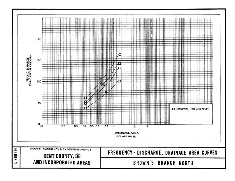
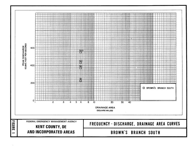
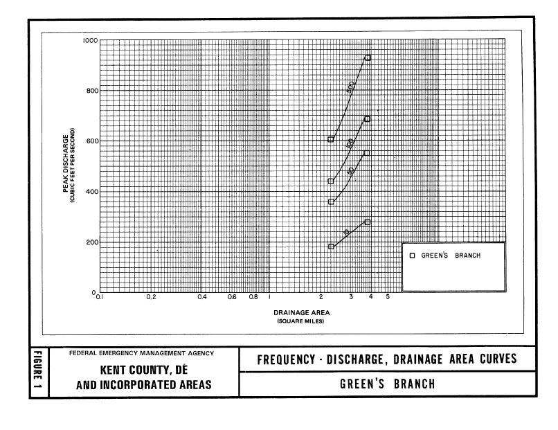
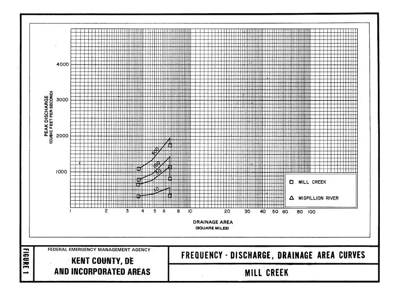
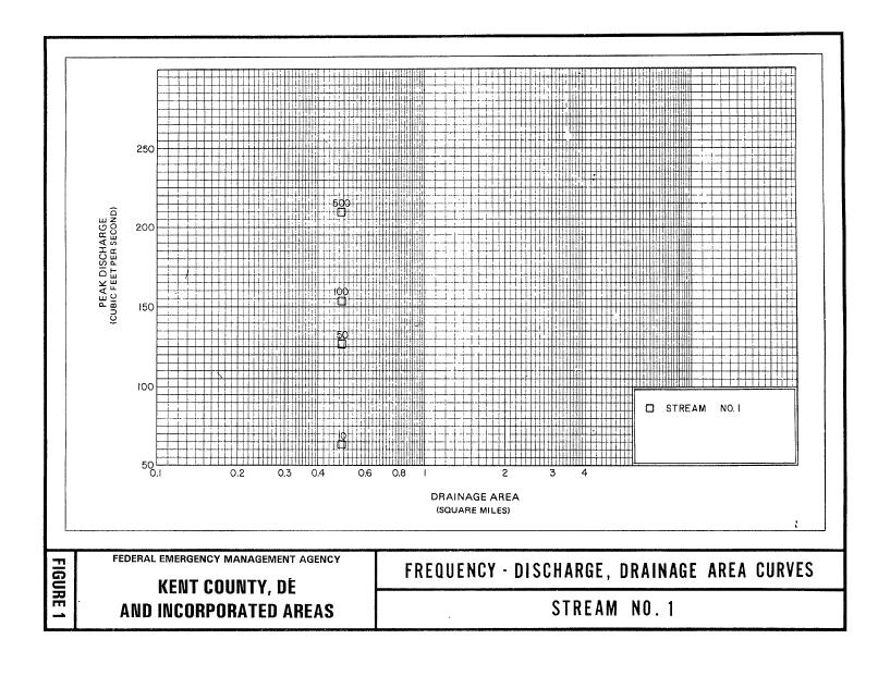
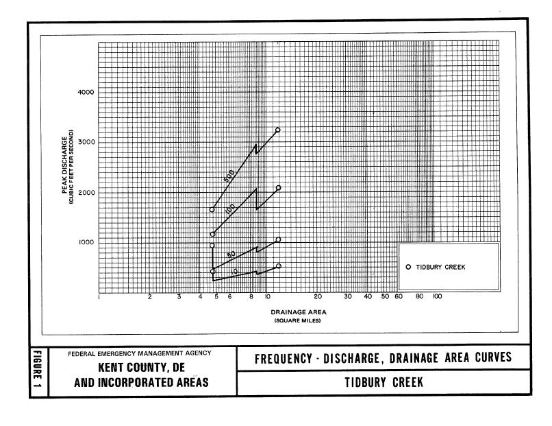
18 For Brown's Branch North, Brown's Branch South, Green's Branch, Isaac Branch, Leipsic River, Mill Creek, Puncheon Branch, Stream No. 1, Tantrough Branch and Tidbury Creek, the available rain gage and stream stage data is sparse. Consequently, due to the lack of data and short-term periods for the data that were available, a log-pearson Type III Method (Water Resources Council, 1967) for determining the frequency discharges in the regions studied could not be properly used. The most accurate hydrology program available for the type of data supplied is the TR-20 program designed by the SCS (U.S. Department of Agriculture, 1965). The rainstorms for the various recurrence intervals used to compute the peak discharges used in this program were taken from the U.S. Weather Bureau Technical Paper No. 40 (U.S. Weather Bureau, 1961). The TR- 20 program was chosen due to the fact that the county is primarily rural and topographically uniform, which makes it well suited for the type of hydrologic methods used by the SCS. The results of the program were tampered where necessary with good engineering judgment and experience in this field. Several additional methods of analyses were used for Brown's Branch North and Brown's Branch South. A method relating peak discharge: to a runoff coefficient and drainage area by use of a regression equation developed for drainage of flat topographic areas was the principal method of analysis (U.S. Department of Agriculture, 1971). Other methods used for comparison of results include application of regional relationships as developed for Kent County, Delaware, by the study contractor from a previous countywide study (Greenhorne & O'Mara Inc., 1975); regional relationships (regression equations) relating to peak discharge with drainage area, a runoff coefficient, and average basin slope as developed in a previous study (Delaware Department of Highways and Transportation, 1972); and a regional log-pearson Type III Study, which includes all available streamflow records for Kent County, Delaware, and additional data generated by a synthetic streamflow model (USACE, 1972). Tantrough Branch peak discharges were determined using R H. Simmons and D. H. Carpenter's Regional Method (Simmons and Carpenter, 1978). The hydrologic analyses of the Isaac Branch within the Town of Camden were also prepared by Greenhorne & O'Mara, Inc., for their FIS for the unincorporated areas of Kent County (U.S. Department of Housing and Urban Development, Unincorporated Areas of Kent, 1975). The calculations were based upon synthetic unit hydrograph techniques established by the SCS (U.S. Department of Agriculture, 1972). This method is appropriate for generally uniform agricultural watersheds, such as that of the St. Jones River, of which Isaac Branch is a tributary. Although the U.S. Geological Survey (USGS) maintains a stream gage on the St. Jones River, it was not considered practical to use a log-pearson Type III analysis as the primary hydrological method because of the relatively short duration of recorded data from this gage which was established in In addition, Kent County and the Towns of Smyrna, Clayton, and the City of Harrington had frequency-discharge drainage curves. These curves delineating 12
19 the frequency discharges vs. drainage area relationships for the streams studied in detail are displayed in Figure 1. The sharp vertical drops in those curves reflect the decrease in discharge caused by storage in the lakes. Downstream decreases in peak discharge on Mill Creek are due to the storage effects of Lake Como. Countywide Analyses The peak flows for streams in Kent County, Delaware, were developed using WRI Report , Technique for Estimating Magnitude and Frequency of Peak Flows in Delaware. Most of the streams in Kent County have never been studied before and have no high water mark information for comparison. For most of the watersheds, the WRI Report method for ungaged streams was used. St. Jones River and Marshyhope Creek are the only streams in the study to have gages with a usable period of record, 33 and 45 years of record, respectively. For gaged streams, the WRI Report describes a computation to weight the computed flow to the observed gage flows while accounting for the number of years the gage was in operation. For the St. Jones River, this resulted in significantly lower flows. For Marshyhope Creek, the gage data moderately raised flows. Typically, stream gage records take precedence over empirical methods of hydrology. However, for the St. Jones watershed, the flows that were not weighted for the gage were used for several reasons. The gage flows are dramatically lower than any other estimation of flows for the basin. The gage records appear to reflect the influence of Silver Lake Dam a short distance upstream. The WRI Report results are consistently close to, but slightly higher than the old FIS flows in this drainage basin. These flows also correspond well with the results of the 1996 study of Maidstone Branch conducted by DNREC. The only flow that is greatly out of line with the WRI Report results is the 1- percent annual chance flow calculated on the Dam Inspection Report, seem unrealistically high, especially compared to the gage data, and was not further investigated. For Marshyhope Creek, the variation in drainage area size from the gage to the other subareas precluded translating the gage weighting factor too far upstream or downstream, so only the flows at points Z and X were weighted. TR-55 was used for independent verification at two sample locations due to concerns raised by the difference between the empirical method results and gage records on St. Jones River and Marshyhope Creek. Cahoon Branch and Green 13
20
21
22
23
24
25
26 Branch were chosen for the investigation because they represent different areas within the county, one in the drainage area of each gage, and were small enough not to exceed the time of concentration limit of TR-55. The lack of relief in Kent County's topography yields significantly longer times of concentration than for comparably sized areas in more uneven terrain. The results of TR-55 verified the WRI report results very well. This reinforced the decision to use the unweighted results for the St. Jones watershed and the weighted results for the Marshyhope watershed. A summary of the drainage area-peak discharge relationships for all streams studied by detailed methods are shown in Table 4, Summary of Discharges, except for Brown's Branch North, Brown's Branch South, Green's Branch, Mill Creek, Stream No. 1, and Tidbury Creek which are shown in Figure 1, Frequency-Discharge, Drainage Area Curves, and Tidy Island Creek, Willow Grove Prong, and Providence Creek, which are continuations of Choptank River, Cow Marsh Creek, and Duck Creek, respectively. TABLE 4 - SUMMARY OF DISCHARGES FLOODING SOURCE AND LOCATION ANDREWS LAKE DRAINAGE AREA (sq. miles) 10- percent chance PEAK DISCHARGES (cfs) 2- percent chance 1- percent chance 0.2- percent chance At downstream end of lake ,490 2,005 3,904 BEAVERDAM DITCH At confluence with Tidy Island Creek ,331 1,685 2,857 CAHOON BRANCH At confluence with Maidstone Branch ,444 1,883 3,400 Approximately 0.6 mile upstream of State Route ,018 1,867 CHOPTANK RIVER Downstream of confluence of Cow Marsh Creek ,438 4,483 5,468 8,508 Upstream of confluence of Cow Marsh Creek ,910 3,582 4,400 6,955 Upstream of confluence of Culbreth Marsh Ditch ,401 2,702 3,365 5,499 COURSEY POND At downstream end of lake ,509 1,942 3,456 20
27 TABLE 4 - SUMMARY OF DISCHARGES- Continued FLOODING SOURCE AND LOCATION COW MARSH CREEK DRAINAGE AREA (sq. miles) 10- percent chance PEAK DISCHARGES (cfs) 2- percent chance 1- percent chance 0.2- percent chance At confluence with Choptank River ,327 2,490 3,055 4,824 COW MARSH CREEK - continued Upstream of confluence of Meredith Branch ,295 1,590 2,518 Upstream of confluence of Iron Mine Branch ,058 1,724 CULBRETH MARSH DITCH At confluence with Choptank River ,706 2,128 3,480 Approximately 2.4 miles upstream of the confluence with Choptank River ,557 1,954 3,239 DUCK CREEK At Smyrna Landing Road ,455 5,555 7,400 13,950 Upstream of confluence With Spring Branch ,804 4,071 5,401 10,085 FORK BRANCH Upstream of confluence with St. Jones River ,957 2,543 4,552 Upstream of Rose Dale Lane GREEN BRANCH At confluence with Marshyhope Creek ,360 1,735 2,983 HORSEPEN ARM At confluence with Marshyhope Ditch ,351 ISAAC BRANCH At U.S. Route ,220 1,540 2,190 LEIPSIC RIVER At eastern corporate limits ,092 3,757 5,244 Approximately 1,550 feet upstream of eastern corporate limits ,062 3,721 5,194 At State Highway ,057 3,715 5,185 LITTLE RIVER At confluence with Morgan Branch ,134 1,466 2,598 At Williams Park
28 TABLE 4 - SUMMARY OF DISCHARGES- Continued FLOODING SOURCE AND LOCATION MAIDSTONE BRANCH DRAINAGE AREA (sq. miles) 10- percent chance PEAK DISCHARGES (cfs) 2- percent chance 1- percent chance 0.2- percent chance At confluence with St. Jones River ,623 3,562 4,680 8,568 Upstream of confluence of Cahoon Branch ,147 2,545 3,347 6,138 PENROSE BRANCH At confluence with Maidstone Branch ,070 1,379 2,428 At Pearsons Comer Road ,287 MARSHYHOPE CREEK At U.S. Route 16 Bridge ,192 4,253 5,312 8,701 At Fishers Bridge Road ,160 3,653 4,360 6,429 Upstream of confluence of Green Branch ,878 3,251 3,908 5,867 MARSHYHOPE DITCH Upstream of confluence of Horsepen Arm ,610 MCCOLLEY POND At downstream of end of lake ,339 1,734 3,146 MCGINNIS POND At downstream end of lake ,578 2,101 4,006 MORGAN BRANCH At confluence with Little River ,253 2,409 PUNCHEON BRANCH At the confluence with St. Jones River ,110 1,510 At CONRAIL RED HOUSE BRANCH At the confluence with Tidbury Creek 1.48 * * 909 * At Lake Front Drive 1.34 * * 820 * Upstream of the confluence of Red House Branch Tributary 1.8 * * 604 * RED HOUSE BRANCH TRIBUTARY At the confluence with Red House Branch.48 * * 685 * ST. JONES RIVER Approximately 1.9 miles downstream of U.S. Route 13 Bridge ,874 6,252 8,201 14,942 At State Route 8 Bridge ,537 5,512 7,219 13,108 At upstream end of Silver Lake ,000 4,243 5,498 9,766 * Data Not Available 22
29 TABLE 4 - SUMMARY OF DISCHARGES- Continued FLOODING SOURCE AND LOCATION DRAINAGE AREA (sq. miles) 10- percent chance PEAK DISCHARGES (cfs) 2- percent chance 1- percent chance 0.2- percent chance TANTROUGH BRANCH Upstream of U.S. Route ,250 1,580 2,650 TAPPAHANNA DITCH At confluence with Tidy Island Creek ,017 2,030 2,557 4,273 Downstream of Hourglass Road ,018 1,698 Upstream end of Mud Mill Pond ,348 2,607 3,251 5,324 TIDBURY CREEK At Route * * 1924 * At Steeles Ridge Road 2.10 * * 1027 * Upstream of the confluence of Tidbury Creek Tributary 3.57 * * 576 * TIDBURY CREEK TRIBUTARY 1 Upstream of the confluence with Tidbury Creek.58 * * 284 * TIDBURY CREEK TRIBUTARY 2 Upstream of the confluence with Tidbury Creek.16 * * 256 * TIDBURY CREEK TRIBUTARY 3 Upstream of the confluence with Tidbury Creek 1.41 * * 794 * * Data Not Available Water-surface elevations for Wyoming Lake were also adopted from the FIS for the unincorporated areas of Kent County (U.S. Department of Housing and Urban Development, 1975). The Stillwater elevations have been determined for the 10-, 2-, 1-, and 0.2-percent annual chance floods for the flooding sources studied by detailed methods and are summarized in Table 5, Summary of Stillwater Elevations. TABLE 5 - SUMMARY OF STILLWATER ELEVATIONS PEAK DISCHARGES (feet*) FLOODING SOURCE AND LOCATION 10-percent 2-percent 1-percent 0.2-percent chance chance chance chance WYOMING LAKE *North American Vertical Datum of
30 This Revision For this revision, hydrologic results from a hydrologic report developed for the Murderkill Watershed by URS Corporation under Purchase Order number for the Delaware Department of Natural Resources and Environmental Control (DNREC) were used to model the streams studied by limited detail methods (URS, 2010). The hydrologic model for the Murderkill Watershed was developed using data obtained from previous studies as well as data gathered from field reconnaissance of Delaware dams and current Geographic Information System (GIS) datasets, National Oceanic and Atmospheric Administration (NOAA) Atlas 14 precipitation data (NOAA, 2009), and U.S. Geological Survey (USGS) gage streamflow data (USGS, 2009). URS prepared a comprehensive hydrologic model of the Murderkill Watershed using GIS mapping tools and the USACE Hydrologic Engineering Center s (HEC) Hydrological Modeling System (HMS): HEC-HMS (version 3.3) (USACE, 2008). ArcGIS 9.2-based (ESRI, 2006) ArcHydro (CRWR, 2007) and HEC-GeoHMS models (USACE, 2003) were also used to complete the HEC- HMS model. Terrain preprocessing was developed using the ArcHydro tool. Basin processing and HEC-HMS model setup were performed using HEC- GeoHMS. A summary of the drainage area-peak discharge relationships for the streams studied by limited detailed methods is shown in Table 6, "Summary of Discharges, Limited Detailed Streams." TABLE 6 - SUMMARY OF DISCHARGES, LIMITED DETAILED STREAMS PEAK DISCHARGES (cfs) FLOODING SOURCE AND LOCATION BEAVERDAM BRANCH Approximately 192 feet downstream of the confluence with Beaverdam Branch Trib 1 Approximately 1,526 feet above the confluence with Beaverdam Branch Trib 1 DRAINAGE AREA (sq. miles) 10- percent chance 2-percent chance 1-percent chance 0.2- percent chance ,160 1,800 2,260 3, BEAVERDAM BRANCH TRIBUTARY 1 Approximately 1,391 feet upstream of confluence with Beaverdam Branch ,275 2,070 2,485 3,250 24
31 TABLE 6 - SUMMARY OF DISCHARGES, LIMITED DETAILED STREAMS- Continued PEAK DISCHARGES (cfs) FLOODING SOURCE AND LOCATION BLACK SWAMP CREEK Approximately 3,620 feet downstream of Little Mastens Corner Approximately 971 feet downstream of Little Mastens Corner Approximately 1,055 feet upstream of Hopkins cemetery Approximately 1,390 feet downstream of State Hwy 12 DRAINAGE AREA (sq. miles) 10- percent chance 2-percent chance 1-percent chance 0.2- percent chance ,799 2,352 4, ,546 2,000 3, ,273 1,636 2, ,080 BROWNS BRANCH Approximately 931 feet upstream of Jackson Ditch Rd BROWNS BRANCH- continued Approximately 517 feet upstream of Doctor Smith Rd Approximately 556 feet downstream of Cluckey Dr. BROWNS BRANCH TRIB 1 Approximately 49 feet upstream of US Hwy 13 Approximately 446 feet upstream of Simmons St DOUBLE RUN Approximately 230 feet upstream of Barney Jenkins Rd/County Hwy 370 Approximately 1214 feet upstream of Irish Hill Rd FAN BRANCH Approximately 248 feet upstream of State Hwy ,817 2,462 4, ,267 2, , , ,774 2,408 4, ,010 1,349 2,
32 TABLE 6 - SUMMARY OF DISCHARGES, LIMITED DETAILED STREAMS- Continued PEAK DISCHARGES (cfs) FLOODING SOURCE AND LOCATION DRAINAGE AREA (sq. miles) 10- percent chance 2-percent chance 1-percent chance 0.2- percent chance HUDSON BRANCH Approximately 309 feet upstream of US Hwy 13 Approximately 440 feet downstream of Firetower Rd Approximately 90.9 feet downstream of Firetower Rd MURDERKILL RIVER Approximately 30 feet upstream of Killens Pond Rd Approximately 39 feet upstream of US Hwy 13 MURDERKILL RIVER- continued Approximately 108 feet downstream of confluence with Fan Branch Approximately 1,021 feet upstream of Little Masons Corner Approximately 4,800 feet above confluence with Beaverdam Branch PRATT BRANCH Approximately 66 feet downstream of Andrews Lake Rd Approximately 263 feet south of Memorial Ave SPRING BRANCH Approximately 406 feet upstream of US Hwy ,071 1,435 2, , ,852 2,626 5, ,148 2,492 3,305 5, ,132 1,463 2, , ,026 1, ,139 2, ,146 26
33 3.2 Hydraulic Analyses Analyses of the hydraulic characteristics of flooding from the sources studied were carried out to provide estimates of the elevations of floods of the selected recurrence intervals. Users should be aware that flood elevations shown on the FIRM represent rounded whole-foot elevations and may not exactly reflect the elevations shown on the Flood Profiles or in the Floodway Data tables in the FIS report. For construction and/or floodplain management purposes, users are encouraged to use the flood elevation data presented in this FIS in conjunction with the data shown on the FIRM. Locations of selected cross sections used in the hydraulic analyses are shown on the Flood Profiles (Exhibit 1). For stream segments for which a floodway was computed (Section 4.2), selected cross-section locations are also shown on the FIRM (Exhibit 2). The hydraulic analyses for this countywide FIS were based on unobstructed flow. The flood elevations shown on the Flood Profiles (Exhibit 1) are thus considered valid only if the hydraulic structures remain unobstructed, operate properly, and do not fail. Pre-countywide Analyses For each community within Kent County that has a previously printed FIS report. The hydrologic analyses described in those reports have been compiled and are summarized below. Cross sections for the backwater analyses for Mill Creek, Green's Branch, Leipsic River, Puncheon Branch, Isaac Branch, Stream No. 1, and Tidbury Creek were compiled using field-surveyed sections which were extended where necessary by using existing USGS topographic maps. These sections were located at close intervals above and below bridges and culverts, in addition to points in the floodplain, in order to determine backwater effects of these structures in urbanized areas. A detailed hydraulic analysis was not performed for Dyke Branch, the Murderkill River, Spring Creek, and Tributary Number 1 to Spring Creek since they are subject to tidal action. Based on this determination, flood profiles were not computed. However, numerous cross sections were surveyed at selected locations, in order that the floodplains could be more accurately defined. Cross sections for the backwater analyses for Brown's Branch North and Brown's Branch South and Tantrough Branch were obtained by field measurement. All bridges and culverts were surveyed to obtain elevation data and structural geometry. Water-surface profiles for Brown's Branch North, Brown's Branch South, Green's Branch, Leipsic River, Stream No. 1, Mill Creek, Puncheon Branch, Isaac 27
34 Branch, Tantrough Branch, and Tidbury Creek were developed using a USACE HEC-2 computer step-backwater model (USACE, 1991). Water-surface elevations in the lakes studied in detail were obtained by flood routing with the TR-20 hydrology program. This was accomplished by deriving rating curves for the spillways and storage elevation curves for each lake. The spillway rating curves for each procedure used by the agency or individual responsible for maintaining the lake. Starting water-surface elevations for Isaac Branch, Leipsic River, Mill Creek, Puncheon Branch, and Tidbury Creek are governed by the tidal elevation on the Delaware Bay. Due to the convergence of the Delaware Bay as it approaches the Delaware River at its north end, the tidal elevations in the Delaware Bay are not uniform. As the tidal surge moves up the bay, the water surface increases as the bay narrows. Therefore, the tidal elevations at the north end of the bay are higher than at the south end. Since there were three distinct points where the rivers studied in detail meet the bay, separate tidal elevations had to be determined for the southern, the central, and the northern regions of the Bay Shore Area. The bay tidal elevations for the recurrence intervals used were derived from using information from a study by the USACE (USACE, 1963). Starting tidal elevations were taken from a tide elevation-frequency curve computed for the Town of Leipsic (U.S. Department of Commerce, 1976; U.S. Department of Housing and Urban Development, City of Lewes, 1975; U.S. Department of Housing and Urban Development, Delaware City, 1975; USACE, 1963). These starting elevations were used, along with riverine data from the hydraulic analysis, in the SCS WSP-2 Computer Program (U.S. Department of Agriculture, 1976). Analysis of resulting profiles showed that riverine flow has no effect on flood elevations within corporate limits, but rather that tides from the Delaware Bay determine flood elevations in the Town of Leipsic. Starting elevations for Brown's Branch North and Brown's Branch South used in the backwater analysis were developed by the slope/area method. Significant backwater-producing structures were identified by field reconnaissance and analysis of the HEC-2 computer model output. The backwater effect of a tributary to Brown's Branch North, located in the vicinity of the intersection of Brown's Branch North and U.S. Highway 13, was considered in the hydraulic analysis of Brown's Branch North. Water-surface elevations for Tantrough Branch were computed using the USACE HEC-2 step-backwater computer model (USACE, 1973). Water-surface elevations in the Town of Smyrna were computed using the USACE HEC-2 step-backwater computer model (USACE, 1973). Flood profiles were drawn showing computed water-surface elevations to an accuracy of 0.5 foot for floods of the selected recurrence intervals. Computed profiles for the Lake Como reach of Mill Creek compared well with elevation data of historical 28
35 floods supplied by local residents and community officials at the coordination meeting. Information for comparison on Green's Branch and Stream No. 1 was unavailable. Significant backwater producing structures were identified by field reconnaissance and analysis of the HEC-2 computer model output. Elevations for Lake Como were determined by standard computerized flood routing techniques (U.S. Department of Agriculture, 1972). High tailwater and submergence effects were considered in the development of discharge curves for Lake Como spillway structures used in the reservoir routing. Elevations determined for the 10-, 2-, 1-, and.2- percent annual chance floods on Lake Como were used as the starting elevations for the backwater analysis of Stream No. 1. The starting elevations for Green's Branch were governed by normal depth computed by slope/area method. Countywide Analyses The hydraulic characteristics of the streams in Kent County were studied to determine the elevations of floodwaters for the 10-, 2-, 1-, and.2- percent annual chance recurrence intervals. These water-surface elevations were computed using the USACE HEC-RAS River Analysis System computer program (USACE, HEC-RAS, 1998). The cross sections for the hydraulic analysis were obtained from the Digital Terrain Model, which was developed from aerial photography flown in February 1998 (USACE, DTM, 1998; USACE, 1993). Along certain portions of Andrews Lake, McColley Pond, McGinnis Pond, and St. Jones River, a profile base line is shown on the maps to represent channel distances as indicated on the flood profiles and floodway data tables. Roughness factors (Manning's n ) were chosen by engineering judgment and were based on inspection of aerial photography and field visits (Table 7). In addition, photographs were taken in vicinity of all structures, and of typical locations for comparison with established published data for determining n values (Ven te Chow, 1959). The channel n and overbank n values for all the streams studied by detailed methods are shown in the tabulation below. TABLE 7 - MANNING'S "n" VALUES Flooding Source Channel n Values Overbank n Values Andrews Lake Beaverdam Ditch Brown's Branch North Brown's Branch South Cahoon Branch Choptank River Tidy Island Creek Coursey Pond Cow Marsh Creek
36 TABLE 7 - MANNING'S "n" VALUES- Continued Overbank n Flooding Source Channel n Values Values Willow Grove Prong Culbreth Marsh Ditch Duck Creek Providence Creek Fork Branch Green Branch Green's Branch Horsepen Arm Isaac Branch Leipsic River Little River Maidstone Branch Penrose Branch Marshyhope Creek Marshyhope Ditch McColley Pond McGinnis Pond Mill Creek Morgan Branch Puncheon Branch St. Jones River Stream No Tantrough Branch Tappahana Ditch Tidbury Creek * * * Data Not Available This Revision The hydraulic model used for this revision to the FIS is the USACE Hydraulic Engineering Center River Analysis System (HEC-RAS), Version 4.0 (USACE, 2008). Topographic data for the floodplain and channel cross sections in the limited detail models was developed using recently acquired Light Detection and Ranging (LiDAR) land data and field measurements of hydraulic and flood control structures. The models also used updated hydrologic data. The models were developed using HEC-RAS 4.0 for the peak 0.2, 1, 2, and 10-percent annual chance frequency storm discharges for the limited detail studied streams. Starting conditions for the hydraulic models were set to normal depth using starting slopes calculated from values taken from the LiDAR data or, where 30
37 applicable, derived from the water surface elevations of existing effective flood elevations. Roughness factors (Manning's n ) used in the hydraulic computations were chosen based on orthophotography and field investigation. Table 8 shows the channel and overbank n values for the streams studied by limited detailed methods. TABLE 8 MANNING S n VALUES- LIMITED DETAIL STUDY STREAMS Stream Channel n Left Overbank n Right Overbank n Beaverdam Branch Beaverdam Branch Tributary 1 Black Swamp Creek Browns Branch Browns Branch Trib Double Run Fan Branch Hudson Branch Murderkill River Pratt Branch Spring Branch Qualifying bench marks within a given jurisdiction that are cataloged by the National Geodetic Survey (NGS) and entered into the National Spatial Reference System (NSRS) as First or Second Order Vertical and have a vertical stability classification of A, B, or C are shown and labeled on the FIRM with their 6- character NSRS Permanent Identifier. Bench marks cataloged by the NGS and entered into the NSRS vary widely in vertical stability classification. NSRS vertical stability classifications are as follows: Stability A: Monuments of the most reliable nature, expected to hold position/elevation well (e.g., mounted in bedrock) Stability B: Monuments which generally hold their position/elevation well (e.g., concrete bridge abutment) Stability C: Monuments which may be affected by surface ground movements (e.g., concrete monument below the frost line) 31
38 Stability D: Mark of questionable or unknown vertical stability (e.g., concrete monument above frost line, or steel witness post) In addition to NSRS bench marks, the FIRM may also show vertical control monuments established by a local jurisdiction; these monuments will be shown on the FIRM with the appropriate designations. Local monuments will only be placed on the FIRM if the community has requested that they be included, and if the monuments meet the aforementioned NSRS inclusion criteria. To obtain elevation, description, and /or location information for bench marks shown on the FIRM for this jurisdiction, please contact the Information Services Branch of the NGS at (301) , or visit their Web site at It is important to note that temporary vertical monuments are often established during the preparation of a flood hazard analysis for the purpose of establishing local vertical control. Although these monuments are not shown on the FIRM, they may be found in the Technical Support Data Notebook associated with this FIS and FIRM. Interested individuals may contact FEMA to access this data. 3.3 Coastal Analysis Coastal analysis, considering storm characteristics and the shoreline and bathymetric characteristics of the flooding sources studied, were carried out to provide estimates of the elevations of floods of the selected recurrence intervals along the shoreline. Users of the FIRM should be aware that coastal flood elevations are provided in Table 9, Summary of Coastal Stillwater Elevations table in this report. If the elevation on the FIRM is higher than the elevation shown in this table, a wave height, wave runup, and/or wave setup component likely exists, in which case, the higher elevation should be used for construction and/or floodplain management purposes. Development along the coast of Kent County is limited to six small isolated areas; Woodland Beach, Pickering Beach, Kitts Hummock, Bowers Beach and South Bowers Beach, and Big Stone Beach. The entire coastline is comprised of a small dune whose elevation varies from four feet to more than nine feet North American Vertical Datum of 1988 (NAVD 88), with the above mentioned areas of development generally situated on the higher ground. Behind the dune, the ground slopes down to large areas of swamp and marshland. Most of this area in the northern half of the county is part of the Bombay Hook National Wildlife Refuge. Much of the area in the southern part of the county is within the Ted Harvey State Wildlife Area. An analysis was performed to establish the frequency peak elevation relationships for coastal flooding in Kent County. The FEMA, Region III office, initiated a study in 2008 to update the coastal storm surge elevations within the states of Virginia, Maryland, and Delaware, and the District of Columbia including the 32
39 Atlantic Ocean, Chesapeake Bay including its tributaries, and the Delaware Bay. The study replaces outdated coastal storm surge stillwater elevations for all FIS Reports in the study area, including Kent County, DE, and serves as the basis for updated FIRMs. Study efforts were initiated in 2008 and concluded in The storm surge study was conducted for FEMA by the USACE and its project partners under Project HSFE03-06-X-0023, NFIP Coastal Storm Surge Model for Region III and Project HSFE03-09-X-1108, Phase II Coastal Storm Surge Model for FEMA Region III. The work was performed by the Coastal Processes Branch (HF-C) of the Flood and Storm Protection Division (HF), U.S. Army Engineer Research and Development Center Coastal & Hydraulics Laboratory (ERDC-CHL). The end-to-end storm surge modeling system includes the Advanced Circulation Model for Oceanic, Coastal and Estuarine Waters (ADCIRC) for simulation of 2- dimensional hydrodynamics (Luettich et. al, 2008). ADCIRC was dynamically coupled to the unstructured numerical wave model Simulating Waves Nearshore (unswan) to calculate the contribution of waves to total storm surge (USACE, 2012.). The resulting model system is typically referred to as SWAN+ADCIRC (USACE, 2012). A seamless modeling grid was developed to support the storm surge modeling efforts. The modeling system validation consisted of a comprehensive tidal calibration followed by a validation using carefully reconstructed wind and pressure fields from three major flood events for the Region III domain: Hurricane Isabel, Hurricane Ernesto, and extratropical storm Ida. Model skill was accessed by quantitative comparison of model output to wind, wave, water level and high water mark observations. The tidal surge in Delaware Bay affects the entire 32 miles on Kent County coastline. The southern two thirds of the coastline, from the Leipsic River southward, is more prone to damaging wave action during high wind events due to the significant fetch over which winds can operate. From the Leipsic River northward, the Delaware Bay narrows considerably as it converges with the Delaware River. In this area, the fetch over which winds can operate for wave generation is significantly less. The storm-surge elevations for the 10-, 2-, 1-, and.2- percent annual chance floods were determined for Delaware Bay and are shown in Table 9, Summary of Coastal Stillwater Elevations. The analyses reported herein reflect the stillwater elevations due to tidal and wind setup effects. 33
40 TABLE 9 - SUMMARY OF COASTAL STILLWATER ELEVATIONS ELEVATION (feet NAVD) FLOODING SOURCE AND LOCATION 10-percent 2-percent 1-percent 0.2-percent chance chance chance chance DELAWARE BAY Entire shoreline within county limits The methodology for analyzing the effects of wave heights associated with coastal storm surge flooding is described in a report prepared by the National Academy of Sciences (NAS, 1977). This method is based on three major concepts. First, depth-limited waves in shallow water reach maximum breaking height that is equal to 0.78 times the stillwater depth. The wave crest is 70 percent of the total wave height above the stillwater level. The second major concept is that wave height may be diminished by dissipation of energy due to the presence of obstructions, such as sand dunes, dikes and seawalls, buildings and vegetation. The amount of energy dissipation is a function of the physical characteristics of the obstruction and is determined by procedures prescribed in NAS Report. The third major concept is that wave height can be regenerated in open fetch areas due to the transfer of wind energy to the water. This added energy is related to fetch length and depth. The Region III coastal analysis involved transect layout, field reconnaissance, erosion analysis, and overland wave modeling including wave setup, wave height analysis and wave runup. Wave heights were computed across transects that were located along coastal and inland bay areas of Kent County, as illustrated on the FIRMs. The transects were located with consideration given to existing transect locations and to the physical and cultural characteristics of the land so that they would closely represent conditions in the locality. Each transect was taken perpendicular to the shoreline and extended inland to a point where coastal flooding ceased. Along each transect, wave heights and elevations were computed considering the combined effects of changes in ground elevation, vegetation, and physical features. The stillwater elevations for a 1% annual chance event were used as the starting elevations for these computations. Wave heights were calculated to the nearest 0.1 foot, and wave elevations were determined at whole-foot increments along the transects. The location of the 3- foot breaking wave for determining the terminus of the Zone VE (area with velocity wave action) was computed at each transect. Along the open coast, the Zone VE designation applies to all areas seaward of the landward toe of the primary frontal dune system. The primary frontal due is defined as the point where the ground profile changes from relatively steep to relatively mild. 34
41 Dune erosion was taken into account along the Delaware Bay coastline. A review of the geology and shoreline type in Kent County was made to determine the applicability of standard erosion methods, and FEMA s standard erosion methodology for coastal areas having primary frontal dunes, referred to as the 540 rule, was used (FEMA, 2007a). This methodology first evaluates the dune s cross-sectional profile to determine whether the dune has a reservoir of material that is greater or less than 540 square feet. If the reservoir is greater than 540 square feet, the retreat erosion method is employed and approximately 540 square feet of the dune is eroded using a standardized eroded profile, as specified in FEMA guidelines. If the reservoir is less than 540 square feet, the remove erosion method is employed where the dune is removed for subsequent analysis, again using a standard eroded profile. The storm surge study provided the return period stillwater elevations required for erosion analyses. Each cross-shore transect was analyzed for erosion, when applicable. Wave height calculations used in this study flood the methodologies described in the FEMA guidance for coastal mapping (FEMA, 2007a). Wave setup results in an increased water level at the shoreline due to the breaking of waves and transfer of momentum to the water column during hurricanes and severe storms. For the Kent County study, wave setup was determined directly from the coupled wave and storm surge model The total stillwater elevation (SWEL) with wave setup was then used for simulations of inland wave propagation conducted using FEMA s Wave Height Analysis for Flood Insurance Studies (WHAFIS) model Version 4.0 (FEMA, 2007b). WHAFIS is a one-dimensional model that was applied to each transect in the study area. The model uses the specified SWEL, the computed wave setup, and the starting wave conditions as input. Simulations of wave transformations were then conducted with WHAFIS taking into account the storm-induced erosion and overland features of each transect. Output from the model includes the combined SWEL and wave height along each cross-shore transect allowing for the establishment of base flood elevations (BFEs) and flood zones from the shoreline to points inland within the study area. Wave runup is defined as the maximum vertical extent of wave uprush on a beach or structure. FEMA s 2007 Guidelines and Specifications require the 2% wave runup level be computed for the coastal feature being evaluated (cliff, coastal bluff, dune, or structure) (FEMA, 2007a). The 2% runup level is the highest 2 percent of wave runup affecting the shoreline during the 1-percent-annual-chance flood event. Each transect defined within the Region III study area was evaluated for the applicability of wave runup, and if necessary, the appropriate runup methodology was selected and applied to each transect. Runup elevations were then compared to WHAFIS results to determine the dominant process affecting BFEs and associated flood hazard levels. Based on wave runup rates, wave overtopping was computed following the FEMA 2007 Guidelines and Specifications. In Kent County, no transects required runup methodology to be applied. 35
42 Computed controlling wave heights at the shoreline range from 6.22 feet at the northern end of the county where the fetch is short to 6.86 feet at the southern end where the fetch is longer. The corresponding wave elevation at the shoreline varies from 13.1 feet NAVD 88 at the northern end to 14.1 feet NAVD 88 at the southern end. The dune along the coast serves to reduce wave height transmitted inland, but the large areas of low-lying marshes which are inundated by the tidal surge allow regeneration of the waves as they proceed inland. In general, the relatively shallow depth of water in the marshes along with the energy dissipating effects of vegetation allows only minor regeneration of the waves. Figure 2, Transect Location Map, illustrates the location of each transect. Along each transect, wave envelopes were computed considering the combined effects of changes in ground elevation, vegetation and physical features. Between transects, elevations were interpolated using topographic maps, land-use and land-cover data, and engineering judgment to determine the aerial extent of flooding. The results of the calculations are accurate until local topography, vegetation, or cultural development within the community undergoes major changes. The transect data for the county are presented in Table 10, Transect Descriptions, which describes the location of each transect. In addition, Table 10, provides the 1-percent annual chance stillwater with wave setup and the maximum wave crest elevations for each transect along coastline. In Table 11, Transect Data, the flood hazard zone and base flood elevations for each transect flooding source is provided, along with the 10-, 2-, 1-, and 0.2-percent annual chance stillwater elevations for the respective flooding source. 36
43 36
44 TABLE 10 - TRANSECT DESCRIPTIONS ELEVATION (ft NAVD 88) 1-PERCENT MAXIMUM ANNUAL CHANCE 1-PERCENT TRANSECT LOCATION STILLWATER ANNUAL CHANCE (at shoreline) WAVE CREST 1 From the Delaware Bay shoreline, approximately 3300 feet southeast of the mouth of the Smyrna River, inland across Route 1, starting at N, W From the Delaware Bay shoreline, approximately 6500 feet southeast of the mouth of the Smyrna River, inland across Route 1, starting at N, W 3 From the Delaware Bay shoreline, approximately 2000 feet north of Pierson Cove (at Persimmon Hummock), inland across Smyrna Leipsic Road, starting at N, W 4 From the Delaware Bay shoreline, approximately at feet of Pierson Cove, inland across Chappel Yeatman Road, starting at N, W 5 From the Delaware Bay shoreline, approximately 6600 feet north of Bombay Hook Point, inland across Road 326, starting at N, W 6 From the Delaware Bay shoreline, approximately at feet of Bombay Hook Point, inland across Smyrna Leipsic Road, starting at N, W 7 From the Delaware Bay shoreline, approximately 400 feet south of Sluice Ditch, inland across Route 9, starting at N, W 8 From the Delaware Bay shoreline, approximately 5700 feet southeast of Sluice Ditch, inland across Route 1, starting at N, W 9 From the Delaware Bay shoreline, approximately 7600 feet north of the Leipsic River, inland across Route 1, starting at N, W
45 TABLE 10 - TRANSECT DESCRIPTIONS- Continued ELEVATION (ft NAVD 88) 1-PERCENT MAXIMUM ANNUAL CHANCE 1-PERCENT TRANSECT LOCATION STILLWATER ANNUAL CHANCE (at shoreline) WAVE CREST 10 From the Delaware Bay shoreline, approximately 1800 feet north of the Leipsic River, inland across Route 1, starting at N, W From the Delaware Bay shoreline, approximately 100 feet south of the mouth of the Leipsic River, inland across Route 1, starting at N, W 12 From the Delaware Bay shoreline, approximately 500 feet north of the mouth of the Simon River, inland across Route 1, starting at N, W 13 From the Delaware Bay shoreline, approximately 4300 feet southeast of the mouth of the Simon River, inland across Route 1, starting at N, W 14 From the Delaware Bay shoreline, approximately 2000 feet north of the mouth of the Mahon River, inland across Route 1, starting at N, W 15 From the Delaware Bay shoreline, approximately 2300 feet south of the mouth of the Mahon River, inland across White Oak Road, starting at N, W 16 From the Delaware Bay shoreline, approximately 4700 feet north of the mouth of the Little River, inland across Little River, starting at N, W 17 From the Delaware Bay shoreline, approximately 600 feet north of the mouth of the Little River, inland across Little River, starting at N, W 18 From the Delaware Bay shoreline, approximately 2700 feet south of the mouth of the Little River, inland across Pipe Elm Branch, starting at N, W
46 TABLE 10 - TRANSECT DESCRIPTIONS- Continued ELEVATION (ft NAVD 88) 1-PERCENT MAXIMUM ANNUAL CHANCE 1-PERCENT TRANSECT LOCATION STILLWATER ANNUAL CHANCE (at shoreline) WAVE CREST 19 From the Delaware Bay shoreline, approximately at feet of the end of Pickering Beach Road, inland across Dover Air Force Base, starting at N, W From the Delaware Bay shoreline, approximately 1000 feet south of Lewis Ditch, inland across Dover Air Force Base, starting at N, W 21 From the Delaware Bay shoreline, approximately at feet of Sand Ditch, inland across Dover Air Force Base, starting at N, W 22 From the Delaware Bay shoreline, approximately at feet of the end of Kitts Hummock Road, inland across St. Jones River, starting at N, W 23 From the Delaware Bay shoreline, approximately 8300 feet north of the mouth of the St. Jones River, inland across Route 10, starting at N, W 24 From the Delaware Bay shoreline, approximately 2900 feet north of the mouth of the St. Jones River, inland across Route 1, starting at N, W 25 From the Delaware Bay shoreline, approximately 300 feet south of the mouth of the St. Jones River, inland across Route 1, starting at N, W 26 From the Delaware Bay shoreline, approximately 700 feet north of the mouth of the Murderkill River, inland across to Route 1, starting at N, W 27 From the Delaware Bay shoreline, approximately 3300 feet south of the mouth of the Murderkill River, inland across Spring Creek, starting at N, W
47 TABLE 10 - TRANSECT DESCRIPTIONS- Continued ELEVATION (ft NAVD 88) 1-PERCENT MAXIMUM ANNUAL CHANCE 1-PERCENT TRANSECT LOCATION STILLWATER ANNUAL CHANCE (at shoreline) WAVE CREST 28 From the Delaware Bay shoreline, approximately 1500 feet northwest of the mouth of Brockonbridge Gut, inland across Browns Branch, starting at N, W From the Delaware Bay shoreline, approximately 1400 feet northwest of Bennetts Pier Road, inland across to Route 1, starting at N, W 30 From the Delaware Bay shoreline, approximately 4800 feet southeast of Bennetts Pier Road, inland across Thompsonville Road, starting at N, W 31 From the Delaware Bay shoreline, approximately 9100 feet southeast of Bennetts Pier Road, inland across to Tolbert Road, starting at N, W 32 From the Delaware Bay shoreline, approximately 700 feet northwest of Big Stone Beach Road, inland across to Tolbert Road, starting at N, W From the Delaware Bay shoreline, approximately 4400 feet southeast of Big Stone Beach Road, inland across to Beaverdam Branch, starting at N, W 34 From the Delaware Bay shoreline, approximately 8600 feet north of the mouth of the Mispillion River, inland across to Route 1, starting at N, W 35 From the Delaware Bay shoreline, approximately 1300 feet north of the mouth of the Mispillion River, inland across to Route 1, starting at N, W
48 TABLE 11 - TRANSECT DATA Flood Source Transect Starting Wave Conditions for the 1% Annual Chance Coordinates Delaware Bay 1 N W Delaware Bay 2 N W Delaware Bay 3 N W Delaware Bay 4 N W Delaware Bay 5 N W Delaware Bay 6 N W Delaware Bay 7 N W Delaware Bay 8 N W Delaware Bay 9 N W Delaware Bay 10 N W Significant Wave Height H s (ft) Peak Wave Period T p (sec) Starting Stillwater Elevations (ft NAVD88) 10% Annual Chance Range of Stillwater Elevations (ft NAVD88) 2% Annual Chance % Annual Chance % Annual Chance
49 TABLE 11 - TRANSECT DATA- Continued Starting Stillwater Elevations (ft NAVD88) Starting Wave Conditions for the 1% Annual Chance Range of Stillwater Elevations (ft NAVD88) Flood Source Transect Coordinates Significant Wave Height H s (ft) Peak Wave Period T p (sec) 10% Annual Chance 2% Annual Chance 1% Annual Chance 0.2% Annual Chance Delaware Bay 11 N W Delaware Bay 12 N W Delaware Bay 13 N W Delaware Bay 14 N W Delaware Bay 15 N W Delaware Bay 16 N W Delaware Bay 17 N W Delaware Bay 18 N W Delaware Bay 19 N W Delaware Bay 20 N W
50 TABLE 11 - TRANSECT DATA- Continued Starting Stillwater Elevations (ft NAVD88) Flood Source Delaware Bay Delaware Bay Delaware Bay Delaware Bay Delaware Bay Delaware Bay Delaware Bay Delaware Bay Delaware Bay Delaware Bay Transect Starting Wave Conditions for the 1% Annual Chance Coordinates 21 N W N W N W N W N W N W N W N W N W N W Significant Wave Height H s (ft) Peak Wave Period T p sec) 10% Annual Chance Range of Stillwater Elevations (ft NAVD88) 2% Annual Chance % Annual Chance % Annual Chance Delaware Bay 31 N W Delaware Bay 32 N W Delaware Bay 33 N W
51 TABLE 11 - TRANSECT DATA- Continued Starting Stillwater Elevations (ft NAVD88) Starting Wave Conditions for the 1% Annual Chance Range of Stillwater Elevations (ft NAVD88) Flood Source Transect Coordinates Significant Wave Height H s (ft) Peak Wave Period T p sec) 10% Annual Chance 2% Annual Chance 1% Annual Chance 0.2% Annual Chance Delaware Bay 34 N W Delaware Bay 35 N W Areas of coastline subject to significant wave attack are referred to as coastal high hazard zones. The USACE has established the 3-foot breaking wave as the criterion for identifying the limit of coastal high hazard zones (USACE, 1975). The 3-foot wave has been determined to be the minimum size wave capable of causing major damage to conventional wood frame of brick veneer structures. The one exception to the 3-foot wave criteria is where a primary frontal dune exists. The limit the coastal high hazard area then becomes the landward toe of the primary frontal dune or where a 3-foot or greater breaking wave exists, whichever is most landward. The coastal high hazard zone is depicted on the FIRMs as Zone VE, where the delineated flood hazard includes wave heights equal to or greater than three feet. Zone AE is depicted on the FIRMs where the delineated flood hazard includes wave heights less than three feet. A depiction of how the Zones VE and AE are mapped is shown in Figure 3. Post-storm field visits and laboratory tests have confirmed that wave heights as small as 1.5 feet can cause significant damage to structures when constructed without consideration to the coastal hazards. Additional flood hazards associated with coastal waves include floating debris, high velocity flow, erosion, and scour which can cause damage to Zone AE-type construction in these coastal areas. To help community officials and property owners recognize this increased potential for damage due to wave action in the AE zone, FEMA issued guidance in December 2008 on identifying and mapping the 1.5-foot wave height line, referred to as the Limit of Moderate Wave Action (LiMWA). While FEMA does not impose floodplain management requirements based on the LiMWA, the LiMWA is provided to help communicate the higher risk that exists in that area. Consequently, it is important to be aware of the area between this inland limit and the Zone VE boundary as it still poses a high risk, though not as high of a risk as Zone VE (see Figure 3). 45

52 FIGURE 3: TRANSECT SCHEMATIC 3.4 Vertical Datum All FISs and FIRMs are referenced to a specific vertical datum. The vertical datum provides a starting point against which flood, ground, and structure elevations can be referenced and compared. Until recently, the standard vertical datum in use for newly created or revised FISs and FIRMs was the National Geodetic Vertical Datum of 1929 (NGVD 29). With the finalization of the Datum NAVD 88, many FIS reports and FIRMs are being prepared using NAVD 88 as the referenced vertical datum. All flood elevations shown in this FIS report and on the FIRM are referenced to NAVD 88. Structure and ground elevations in the county must, therefore, be referenced to NAVD 88. It is important to note that adjacent counties may be referenced to NGVD 29. This may result in differences in base flood elevations (BFEs) across the county boundaries between the counties. The average datum shift from NGVD 29 to NAVD 88 for Kent County used was -0.8 feet. For information regarding conversion between the NGVD and NAVD, visit the National Geodetic Survey website at or contact the National Geodetic Survey at the following address: NGS Information Services NOAA, N/NGS12 National Geodetic Survey SSMC-3, #
53 1315 East-West Highway Silver Spring, Maryland (301) FLOODPLAIN MANAGEMENT APPLICATIONS The NFIP encourages State and local governments to adopt sound floodplain management programs. To assist in this endeavor, each FIS provides 1-percent annual chance floodplain data, which may include a combination of the following: 10-, 2-, 1-, and 0.2-percent-annual-chance flood elevations; delineations of the 1- and 0.2-percent annual chance floodplains; and 1-percent annual chance floodway. This information is presented on the FIRM and in many components of the FIS, including Flood Profiles, and Floodway Data Tables add Summary of Stillwater Elevations Tables. Users should reference the data presented in the FIS as well as additional information that may be available at the local community map repository before making flood elevation and/or floodplain boundary determinations. 4.1 Floodplain Boundaries To provide a national standard without regional discrimination, the 1-percent annual chance flood has been adopted by FEMA as the base flood for floodplain management purposes. The 0.2-percent annual chance flood is employed to indicate additional areas of flood risk in the community. For the streams studied in detail, the 1-percent and 0.2-percent annual chance floodplains have been delineated using the flood elevations determined at each cross section. For the May 2003 countywide FIS, flood boundaries were determined with the use of an Arc/Info software application developed by the USACE, Philadelphia District. The computer-generated floodplain boundary check plots were printed, reviewed for accuracy noting any necessary changes. Minor adjustments to the digital floodplain boundaries, including any necessary edge matching, were made in the Arc/Info environment. Locations of the floodway boundaries were marked only at the cross sections, the floodway was hand drawn on the preliminary printouts of the maps connecting the computer-generated markers. Since the cross sections are relatively closely spaced in this study producing many floodway markers (made possible by using a DTM as a source for topographic information), delineation of the floodway was straightforward and required minimal engineering judgment. The floodway was integrated into the digital database using Arc/Info software. For this FIS revision, riverine flood boundaries were determined with the use of ArcMap 10.0 Software (ESRI, 2012). The computer-generated floodplain boundaries were reviewed for accuracy noting any necessary changes. Minor adjustments to the digital floodplain boundaries, including any necessary edge matching, were made in the ArcMap environment. The terrain source used to 47
54 delineate the floodplain boundaries for both riverine and coastal analysis was 2007 LiDAR obtained from the Delaware DataMIL (DGS, 2010). The 1- and 0.2-percent-annual-chance floodplain boundaries are shown on the FIRM. On this map, the 1-percent-annual-chance floodplain boundary corresponds to the boundary of the areas of special flood hazards (Zones A, AE, and VE), and the 0.2-percent-annual-chance floodplain boundary corresponds to the boundary of areas of moderate flood hazards. In cases where the 1- and 0.2-percent-annual-chance floodplain boundaries are close together, only the 1-percent-annual-chance floodplain boundary has been shown. Small areas within the floodplain boundaries may lie above the flood elevations, but cannot be shown due to limitations of the map scale and/or lack of detailed topographic data. For the streams studied by approximate methods, only the 1-percent-annual-chance floodplain boundary is shown on the FIRM (Exhibit 2). 4.2 Floodways Encroachment on floodplains, such as structures and fill, reduces flood-carrying capacity, increases flood heights and velocities, and increases flood hazards in areas beyond the encroachment itself. One aspect of floodplain management involves balancing the economic gain from floodplain development against the resulting increase in flood hazard. For purposes of the NFIP, a floodway is used as a tool to assist local communities in this aspect of floodplain management. Under this concept, the area of the 1-percent annual chance floodplain is divided into a floodway and a floodway fringe. The floodway is the channel of a stream, plus any adjacent floodplain areas, that must be kept free of encroachment so that the 1-percent annual chance flood can be carried without substantial increases in flood heights. Minimum Federal standards limit such increases to 1.0 foot, provided that hazardous velocities are not produced. The floodways in this study are presented to local agencies as a minimum standard that can be adopted directly or that can be used as a basis for additional floodway studies. The floodways presented in this study were computed for certain stream segments on the basis of equal conveyance reduction from each side of the floodplain. Floodway widths were computed at cross sections. Between cross sections, the floodway boundaries were interpolated. The results of the floodway computations are tabulated for selected cross sections in Table 12, Floodway Data. The computed floodways are shown on the FIRM (Exhibit 2). In cases where the floodway and 1-percent annual chance floodplain boundaries are either close together or collinear, only the floodway boundary is shown. The floodway for Brown's Branch South, Isaac Branch, Leipsic River, Mill Creek, Puncheon Branch, and Tidbury Creek were computed on the basis of equal conveyance reduction from each side of the floodplain. The results of these 48
55 computations are tabulated at selected cross sections for each stream studied in detail. Near the mouths of streams studied in detail, floodway computations are made without regard to flood elevations on the receiving water body. Therefore, "Without Floodway" elevations presented in Table 12 for certain downstream cross sections of Green's Branch, Mill Creek, Puncheon Branch, St. Jones River, and Tidbury Creek are lower than the regulatory flood elevations in that area, which must take into account the 1-percent annual chance flooding due to backwater from other sources. Tantrough Branch has a floodway that extends beyond the county boundary. The following detailed studied streams do not have computed floodways: Beaverdam Ditch, Brown's Branch North, Choptank River, Tidy Island Creek, Coursey Pond, Cow Marsh Creek, Willow Grove Prong, Culbreth Marsh Ditch, Duck Creek, Providence Creek, Green Branch, Horsepen Arm, Little River, Marshyhope Creek, McColley Pond, Morgan Branch, Penrose Branch, and Tappahanna Ditch Encroachment into areas subject to inundation by floodwaters having hazardous velocities aggravates the risk of flood damage, and heightens potential flood hazards by further increasing velocities. A listing of stream velocities at selected cross sections is provided in Table 12, "Floodway Data." To reduce the risk of property damage in areas where the stream velocities are high, the community may wish to restrict development in areas outside the floodway. No floodways have been computed for streams studied by limited detail methods. The area between the floodway and 1-percent annual chance floodplain boundaries is termed the floodway fringe. The floodway fringe encompasses the portion of the floodplain that could be completely obstructed without increasing the water-surface elevation of the 1-percent annual chance flood by more than 1.0 foot at any point. Typical relationships between the floodway and the floodway fringe and their significance to floodplain development are shown in Figure 4, "Floodway Schematic. 49
56 Figure 4: FLOODWAY SCHEMATIC 5.0 INSURANCE APPLICATIONS For flood insurance rating purposes, flood insurance zone designations are assigned to a community based on the results of the engineering analyses. These zones are as follows: Zone A Zone A is the flood insurance rate zone that corresponds to the 1-percent-annual-chance floodplains that are determined in the FIS report by approximate methods. Because detailed hydraulic analyses are not performed for such areas, no BFEs or depths are shown within this zone. Zone AE Zone AE is the flood insurance rate zone that corresponds to the 1-percent-annual-chance floodplains that are determined in the FIS report by detailed methods. Whole-foot BFEs derived from the detailed hydraulic analyses are shown at selected intervals within this zone. 59
57 Zone VE Zone VE is the flood insurance rate zone that corresponds to the 1-percent-annual-chance coastal floodplains that have additional hazards associated with storm waves. Whole-foot BFEs derived from the detailed hydraulic analyses are shown at selected intervals within this zone. Zone X Zone X is the flood insurance rate zone that corresponds to areas outside the 0.2-percent-annual-chance floodplain, areas within the 0.2-percent-annual-chance floodplain, areas of 1-percent-annual-chance flooding where average depths are less than 1 foot, areas of 1-percent-annual-chance flooding where the contributing drainage area is less than 1 square mile (sq. mi.), and areas protected from the base flood by levees. No BFEs or depths are shown within this zone. 6.0 FLOOD INSURANCE RATE MAP The FIRM is designed for flood insurance and floodplain management applications. For flood insurance applications, the map designates flood insurance rate zones as described in Section 5.0 and, in the 1-percent-annual-chance floodplains that were studied by detailed methods, shows selected whole-foot BFEs or average depths. Insurance agents use zones and BFEs in conjunction with information on structures and their contents to assign premium rates for flood insurance policies. For floodplain management applications, the map shows by tints, screens, and symbols, the 1- and 0.2-percent-annual-chance floodplains, floodways, and the locations of selected cross sections used in the hydraulic analyses and floodway computations. The countywide FIRM presents flooding information for the entire geographic area of Kent County. Previously, separate FIRMs were prepared for each identified floodprone incorporated community of the county. The countywide FIRM also includes flood hazard information that was presented separately on Flood Boundary and Floodway Maps, where applicable. Historical data relating to the maps prepared for each community, up to and include the countywide FIS, are presented in Table 13, Community Map History. 60
58 TABLE 13 COMMUNITY NAME INITIAL IDENTIFICATION FLOOD HAZARD BOUNDARY MAP REVISIONS DATE FIRM EFFECTIVE DATE FIRM REVISIONS DATE Bowers, Town of August 9, 1974 None July 2, 1980 September 2, 1982 May 5, 2003 Camden, Town of May 24, 1974 December 12, 1975 September 16, 1981 May 5, 2003 Cheswold, Town of August 9, 1974 None January 7, 1977 May 5, 2003 Clayton, Town of May 17, 1974 October 24, 1975 June 1, 1977 May 5, 2003 Dover, City of May 31, 1974 July 22, 1977 September 16, 1982 May 5, 2003 January 2, 1976 Felton, Town of August 9, 1974 December 12, 1975 January 7, 1977 May 5, 2003 Frederica, Town of May 17, 1974 December 26, 1975 January 2, 1981 May 5, 2003 Harrington, City of May 17, 1974 December 19, 1975 June 1, 1977 May 5, 2003 Kent County (Unincorporated Areas) June 27, 1975 None March 15, 1978 March 2, 1983 October 1, 1983 April 2, 1992 May 5, 2003 Leipsic, Town of August 9, 1974 January 9, 1976 September 29, 1978 May 5, 2003 Little Creek, Town of August 9, 1974 December 12, 1975 January 17, 1979 August 3, 1992 May 5, 2003 Smyrna, Town of May 10, 1974 September 26, 1975 January 9, 1976 June 1, 1977 March 10, 1978 January 15, 1982 May 5, 2003 Woodside, Town of May 5, 2003 None May5, 2003 None Wyoming, Town of May 24,1974 December 26, 1975 March 16, 1981 May 5, 2003 FEDERAL EMERGENCY MANAGEMENT AGENCY KENT COUNTY, DE AND INCORPORATED AREAS COMMUNITY MAP HISTORY
59 7.0 OTHER STUDIES Information pertaining to revised and unrevised flood hazards for each jurisdiction within Kent County has been compiled into this FIS. Therefore, this FIS supersedes all previously printed FIS reports, and FIRMs for all of the incorporated and unincorporated jurisdictions within Kent County. 8.0 LOCATION OF DATA Information concerning the pertinent data used in preparation of this FIS can be obtained by contacting FEMA, Federal Insurance and Mitigation Division, One Independence Mall, Sixth Floor, 615 Chestnut Street, Philadelphia, Pennsylvania BIBLIOGRAPHY AND REFERENCES Center for Research in Water Resources (CRWR), University of Texas at Austin, and the Environmental Systems Research Institute, Inc. (ESRI). (2007). ArcGIS Hydro Data Model (ArcHydro). Version 1.2 for ArcGIS 9.2. Austin, TX. Delaware Coastal Management Program. (September 1977). Coastal Storm Damage , Technical Report Number 4. Delaware Geological Survey (DGS). (2010). Delaware DataMIL Kent County 2007 LiDAR data, accessed Delaware Department of Highways and Transportation. (December 1972). Peak Rates of Runoff for Small Watersheds in Delaware. C. H. Hu (author). ESRI (Environmental Systems Resource Institute). (2010). ArcMap Redlands, California. ESRI (Environmental Systems Resource Institute), (2006) ArcGIS 9.2. Redlands, California. Federal Emergency Management Agency, (2007a). Atlantic Ocean and Gulf of Mexico Update Coastal Guidelines Update. Washington, DC. Federal Emergency Management Agency (2007b). Wave Height Analysis for Flood Insurance Studies (WHAFIS), Version 4.0. Washington, DC, August Federal Emergency Management Agency. (May 5, 2003). Flood Insurance Study, New Castle County, Delaware and Incorporated Areas. Washington, D.C. 62
60 Greenhorne & O'Mara, Inc. (August 1975). Delaware. Flood Insurance Study, Kent County, Luettich, R. A. and J.J Westerink. A (Parallel) Advanced Circulation Model for Oceanic, Coastal and Estuarine Waters (ADCIRC). Version (February 6, 2008). University of North Carolina at Chapel Hill, Institute of Marine Sciences. Morehead City, NC National Academy of Sciences.(NAS) (1977). Action Effects Associated with Storm Surges. Methodology for Calculating Wave National Oceanic and Atmospheric Administration (NOAA). (2009). Atlas 14 Volume 2, Version 3 [Online] Hydrometeorological Design Studies Center (HDSC), Precipitation Frequency Data Server (PFDS). Simmons, R. H., and. D. H. Carpenter. (September 1978). Technique for Estimating Magnitude and Frequency of Floods in Delaware, Water-Resources Investigations Open-File Report. U.S. Geological Survey. URS Corporation. (January 2010). Hydrologic Analysis of Murderkill Watershed, Kent County, Delaware, in Support of the Murderkill Watershed Management Plan. Gaithersburg, MD. U.S. Army Core of Engineers. (2012) ERDC/CHL TR11-X. FEMA Region 3 Storm Surge Study Coastal Storm Surge Analysis: Modeling System Validation Submission No.2. US Army Corps of Engineers U.S. Army Corps of Engineers, Hydrologic Engineering Center. (2008). River Analysis System, (HEC-RAS) Version 4.0. Davis, California. U.S. Army Corps of Engineers, Hydrologic Engineering Center. (March 2008). Hydrologic Modeling System, (HEC-HMS) Version 3.3. Davis, California. U.S. Army Corps of Engineers, Hydrologic Engineering Center. (2003). Geospatial Hydrologic Modeling Extension, (HEC-GeoHMS). Davis, California. U.S. Army Corps of Engineers, Hydrologic Engineering Center. (September 1998). HEC-RAS River Analysis System, Version 2.2. Davis, California. U.S. Army Corps of Engineers, Philadelphia District, Flood Plain Management Services Branch. (1998). Digital Terrain Model (DTM): Kent County, Delaware FIS. 4-foot contour accuracy, digital layers include: Triangulated Irregular Network (TIN), transportation, hydrography, spot elevations, corporate limits, and orthophotography, developed by Tetra Tech, Inc. 63
61 U.S. Army Corps of Engineers, Philadelphia District, Flood Plain Management Services Branch. (1993). CROSS, Arc/Info software application, developed by Flood Plain Management Services Branch. Philadelphia District. U.S. Army Corps of Engineers, Hydrologic Engineering Center. (February 1991). HEC- 2 Water-Surface Profiles, Generalized Computer Program. Davis, California. U.S. Army Corps of Engineers, Galveston District, (June 1975). Guidelines for Identifying Coastal High Hazard Zones. Galveston, Texas. U.S. Army Corps of Engineers, Philadelphia District, Hydrologic Engineering Center. (October 1973). HEC-2 Water-Surface Profiles. Generalized Computer Program. Davis, California. U.S. Army Corps of Engineers, Hydrologic Engineering Center. (July 1972). Regional Frequency Computations. U.S. Army Corps of Engineers, Hydrologic Engineering Center. (1963). Frequency of High Tides, Hurricane Survey, Delaware River and Bay, (Pennsylvania, New Jersey, and Delaware). U.S. Army Corps of Engineers, Philadelphia District. (1963). Hurricane Study, Delaware River and Bay, Pennsylvania, New Jersey. and Delaware. U.S. Census Bureau (2011). State & county Quickfacts: Kent County, DE. Retrieved August 02,2012, from U.S. Department of Agriculture, Soil Conservation Service. (August 1976). Technical Release No. 61, WSP 2 Computer Program. U.S. Department of Agriculture, Soil Conservation Service. (August 1972). National Engineering Handbook, Section 4, Hydrology. Washington D.C. U.S. Department of Agriculture, Soil Conservation Service. (May 1971). National Engineering Handbook, Section 16- Drainage of Agricultural Land, Chapter 5, pages 5.1 to U.S. Department of Agriculture, Soil Conservation Service. (May 1965). User's Manual for Computer Program for Project Formulation- Hydrology, Technical Release 20. U.S. Department of Commerce, National Oceanic and Atmospheric Administration, National Weather Service. (August 1976). NOAA Technical Memorandum NWS 64
62 HYDR0-32, Storm Tide Frequency Analysis for the Open Coast of Virginia, Maryland and Delaware. Silver Spring, Maryland. U.S. Department of Housing and Urban Development, Federal Insurance Administration. (June 27, 1975). Flood Insurance Study, Kent County, Delaware (Unincorporated Areas). Washington, D.C. U.S. Department of Housing and Urban Development, Federal Insurance Administration. (December 12, 1975). Flood Insurance Study, City of Lewis, Sussex County, Delaware. Washington, D.C. U.S. Department of Housing and Urban Development, Federal Insurance Administration. (December 19, 1975). Flood Insurance Study, City of Delaware City, New Castle County, Delaware. Washington, D.C. U.S. Geological Survey (USGS). (2009), Surface Water Data. [Online]. U.S. Weather Bureau, Technical Paper No. 40. (May 1961). Rainfall Frequency Atlas for the United States. Ven Te Chow. (1959). Open Channel Hydraulics. McGraw-Hill Books: New York. Water Resources Council. (December 1967). A Uniform Technique for Determining Flood Flow Frequencies, Bulletin
63 FEDERAL EMERGENCY MANAGEMENT AGENCY KENT COUNTY, DE AND INCORPORATED AREAS FLOOD PROFILES COURSEY POND YEAR BACKWATER FROM DELAWARE BAY M N O A B C D E F G H I J K L STREAM DISTANCE IN FEET ABOVE CARPENTER BRIDGE ROAD 17P DOWNSTREAM FLOOD ELEVATIONS CONTROLLED BY DELAWARE BAY CANTERBURY ROAD DAM LEGEND 500-YEAR FLOOD 100-YEAR FLOOD 50-YEAR FLOOD 10-YEAR FLOOD STREAM BED CROSS SECTION LOCATION ELEVATION IN FEET (NAVD)
64 FEDERAL EMERGENCY MANAGEMENT AGENCY KENT COUNTY, DE AND INCORPORATED AREAS FLOOD PROFILES DUCK CREEK YEAR BACKWATER FROM DELAWARE BAY I A B C D E F G H STREAM DISTANCE IN FEET ABOVE LIMIT OF DETAILED STUDY* *LIMIT OF DETAILED STUDY LOCATED APPROXIMATELY 5815 FEET UPSTREAM OF CONFLUENCE WITH SMYRNA RIVER 30P DOWNSTREAM FLOODING ELEVATIONS CONTROLLED BY DELAWARE BAY SMYRNA LANDING ROAD STATE ROUTE 1 LEGEND 500-YEAR FLOOD 100-YEAR FLOOD 50-YEAR FLOOD 10-YEAR FLOOD STREAM BED CROSS SECTION LOCATION ELEVATION IN FEET (NAVD)
65 FEDERAL EMERGENCY MANAGEMENT AGENCY KENT COUNTY, DE AND INCORPORATED AREAS FLOOD PROFILES DUCK CREEK YEAR BACKWATER FROM DELAWARE BAY P Q R S J K L M N O STREAM DISTANCE IN FEET ABOVE LIMIT OF DETAILED STUDY 31P US ROUTE 13 CONFLUENCE OF GREEN'S BRANCH NORTH MAIN STREET DAM DAM LEGEND 500-YEAR FLOOD 100-YEAR FLOOD 50-YEAR FLOOD 10-YEAR FLOOD STREAM BED CROSS SECTION LOCATION ELEVATION IN FEET (NAVD)
66 FEDERAL EMERGENCY MANAGEMENT AGENCY KENT COUNTY, DE AND INCORPORATED AREAS FLOOD PROFILES LEIPSIC RIVER STREAM DISTANCE IN FEET ABOVE CONFLUENCE WITH DELAWARE BAY 51P DOWNSTREAM FLOOD ELEVATIONS CONTROLLED BY DELAWARE BAY US ROUTE 13 LIMIT OF DETAILED STUDY LEGEND 500-YEAR FLOOD 100-YEAR FLOOD DAM 50-YEAR FLOOD 10-YEAR FLOOD STREAM BED A B C D E CROSS SECTION LOCATION ELEVATION IN FEET (NAVD)
67 FEDERAL EMERGENCY MANAGEMENT AGENCY KENT COUNTY, DE AND INCORPORATED AREAS FLOOD PROFILES LITTLE RIVER YEAR BACKWATER FROM DELAWARE BAY K L A B C D E F G H I J STREAM DISTANCE IN FEET ABOVE CONFLUENCE OF MORGAN BRANCH 52P CONFLUENCE OF MORGAN BRANCH STATE ROUTE 8 CULVERT LEGEND 500-YEAR FLOOD 100-YEAR FLOOD 50-YEAR FLOOD 10-YEAR FLOOD STREAM BED DOWNSTREAM FLOOD ELEVATIONS CONTROLLED BY DELAWARE BAY CROSS SECTION LOCATION ELEVATION IN FEET (NAVD)
68 FEDERAL EMERGENCY MANAGEMENT AGENCY KENT COUNTY, DE AND INCORPORATED AREAS FLOOD PROFILES MILL CREEK TOR = 41.6 FEET F G D A B C E STREAM DISTANCE IN FEET ABOVE CONFLUENCE WITH SMYRNA RIVER 0 74P US ROUTE 13 MAIN STREET SOUTH CARTER ROAD LIMIT OF DETAILED STUDY 100-YEAR BACKWATER FROM DELAWARE BAY DOWNSTREAM FLOOD ELEVATIONS CONTROLLED BY DELAWARE BAY RAILROAD LEGEND 500-YEAR FLOOD LAKE COMO DAM 100-YEAR FLOOD 50-YEAR FLOOD 10-YEAR FLOOD STREAM BED CROSS SECTION LOCATION ELEVATION IN FEET (NAVD)
69 FEDERAL EMERGENCY MANAGEMENT AGENCY KENT COUNTY, DE AND INCORPORATED AREAS FLOOD PROFILES MORGAN BRANCH YEAR BACKWATER FROM LITTLE RIVER CULVERT P O E A B C D F G H I J K L M N STREAM DISTANCE IN FEET ABOVE CONFLUENCE WITH LITTLE RIVER 75P CONFLUENCE WITH LITTLE RIVER PRIVATE ROAD LITTLE CREEK ROAD CULVERT Q LEGEND 500-YEAR FLOOD 100-YEAR FLOOD 50-YEAR FLOOD 10-YEAR FLOOD STREAM BED CROSS SECTION LOCATION ELEVATION IN FEET (NAVD)
70 FEDERAL EMERGENCY MANAGEMENT AGENCY KENT COUNTY, DE AND INCORPORATED AREAS FLOOD PROFILES PUNCHEON BRANCH 100-YEAR BACKWATER FROM DELAWARE BAY K D I A B C E F G H J CROSS SECTION LOCATION STREAM DISTANCE IN FEET ABOVE CONFLUENCE WITH ST. JONES RIVER 77P CONFLUENCE WITH ST. JONES RIVER U.S. ROUTE 113A (S. STATE STREET) U.S. ROUTE 13 DUPONT HIGHWAY U.S. ROUTE 13A (S. GOVERNORS AVENUE) DOWNSTREAM FLOODING ELEVATIONS CONTROLLED BY DELAWARE BAY LEGEND 500-YEAR FLOOD 100-YEAR FLOOD 50-YEAR FLOOD 10-YEAR FLOOD STREAM BED ELEVATION IN FEET (NAVD)
71 YEAR BACKWATER FROM DELAWARE BAY DOWNSTREAM FLOOD ELEVATIONS CONTROLLED BY DELAWARE BAY FLOOD PROFILES ST. JONES RIVER ELEVATION IN FEET (NAVD) LEGEND 500-YEAR FLOOD -15 A B C D E F G H 100-YEAR FLOOD 50-YEAR FLOOD 10-YEAR FLOOD *LIMIT OF DETAILED STUDY IS APPROXIMATELY 2,075 FEET UPSTREAM OF EAST LEBANON ROAD STREAM DISTANCE IN FEET ABOVE LIMIT OF DETAILED STUDY* STREAM BED CROSS SECTION LOCATION FEDERAL EMERGENCY MANAGEMENT AGENCY KENT COUNTY, DE 79P AND INCORPORATED AREAS
72 YEAR BACKWATER FROM DELAWARE BAY FLOOD PROFILES ST. JONES RIVER ELEVATION IN FEET (NAVD) LEGEND 500-YEAR FLOOD I J K L M N O P US ROUTE 13 STREAM DISTANCE IN FEET ABOVE LIMIT OF DETAILED STUDY* Q R S T U V 100-YEAR FLOOD 50-YEAR FLOOD 10-YEAR FLOOD STREAM BED CROSS SECTION LOCATION FEDERAL EMERGENCY MANAGEMENT AGENCY KENT COUNTY, DE 80P AND INCORPORATED AREAS
73 FEDERAL EMERGENCY MANAGEMENT AGENCY KENT COUNTY, DE AND INCORPORATED AREAS FLOOD PROFILES ST. JONES RIVER AH AI AJ AK AL AF W X Y Z AA AB AC AD AE AG STREAM DISTANCE IN FEET ABOVE LIMIT OF DETAILED STUDY* 81P COURT STREET E. LOOCKERMAN STREET STATE ROUTE 8 (E. DIVISIION STREET) DAM SILVER LAKE DAM LEGEND 500-YEAR FLOOD 100-YEAR FLOOD 50-YEAR FLOOD 10-YEAR FLOOD STREAM BED CROSS SECTION LOCATION ELEVATION IN FEET (NAVD)
74 FEDERAL EMERGENCY MANAGEMENT AGENCY KENT COUNTY, DE AND INCORPORATED AREAS FLOOD PROFILES TIDBURY CREEK 100-YEAR BACKWATER FROM DELAWARE BAY A B C D E F G H I STREAM DISTANCE IN FEET ABOVE CONFLUENCE WITH DELAWARE BAY 94P S. STATE ROUTE 113A STATE ROUTE 29 STATE ROUTE 360 DAM DOWNSTREAM FLOOD ELEVATIONS CONTROLLED BY DELAWARE BAY LEGEND 500-YEAR FLOOD 100-YEAR FLOOD 50-YEAR FLOOD 10-YEAR FLOOD STREAM BED CROSS SECTION LOCATION ELEVATION IN FEET (NAVD)
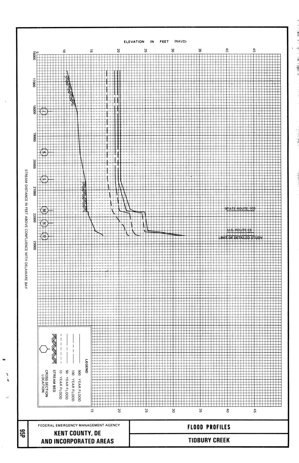
75
SUSSEX COUNTY, DELAWARE AND INCORPORATED AREAS
 VOLUME 1 OF 3 SUSSEX COUNTY, DELAWARE AND INCORPORATED AREAS COMMUNITY COMMUNITY NUMBER COMMUNITY COMMUNITY NUMBER BETHANY BEACH, TOWN OF 105083 LAUREL, TOWN OF 100040 BETHEL, TOWN OF 100055 LEWES, CITY
Sussex County, DE Preliminary Study Overview
 Sussex County, DE Preliminary Study Overview Coastal study scope: 102 miles of entire County shoreline Revised 102 panels for coastal study Riverine study scope: 14 streams, 67.1 miles, within the Nanticoke
MADISON COUNTY, ILLINOIS AND INCORPORATED AREAS
 VOLUME 2 OF 2 MADISON COUNTY, ILLINOIS AND INCORPORATED AREAS * * * COMMUNITY COMMUNITY NAME NUMBER ALHAMBRA, VILLAGE OF 170270 ALTON, CITY OF 170437 BETHALTO, VILLAGE OF 170438 COLLINSVILLE, CITY OF 170439
JEFFERSON COUNTY, ARKANSAS AND INCORPORATED AREAS
 JEFFERSON COUNTY, ARKANSAS Community Name Community Number ALTHEIMER, CITY OF 050107 HUMPHREY, CITY OF 050108 JEFFERSON COUNTY 050440 (UNINCORPORATED AREAS) PINE BLUFF, CITY OF 050109 REDFIELD, CITY OF
VOLUME 2 OF 5 VOLUSIA COUNTY, FLORIDA AND INCORPORATED AREAS COMMUNITY NAME NUMBER COMMUNITY NAME NUMBER
 VOLUME 2 OF 5 VOLUSIA COUNTY, FLORIDA AND INCORPORATED AREAS COMMUNITY NAME NUMBER COMMUNITY NAME NUMBER DAYTONA BEACH, CITY OF 125099 NEW SMYRNA BEACH, CITY OF 125132 DAYTONA BEACH SHORES, CITY OF 125100
Federal Emergency Management Agency FLOOD INSURANCE STUDY NUMBER 48423CV001B. Smith County. Preliminary May 9, 2011
 VOLUME 1 of 2 SMITH COUNTY, TEXAS Community Name Community Number Smith County ARP, CITY OF 480567 BULLARD, CITY OF* 480568 HIDEAWAY, CITY OF 480200 LINDALE, CITY OF 480569 NEW CHAPEL HILL, CITY OF 480157
GALLATIN COUNTY, MONTANA AND INCORPORATED AREAS
 GALLATIN COUNTY, MONTANA AND INCORPORATED AREAS Community Name Community Number * BELGRADE, CITY OF 300105 BOZEMAN, CITY OF 300028 GALLATIN COUNTY UNINCORPORATED AREAS 300027 * MANHATTAN, TOWN OF 300034
Flood Insurance Study
 Flood Insurance Study Tulsa County, Oklahoma and Incorporated Areas VOLUME 5 of 7 COMMUNITY NAME COMMUNITY NO. Bixby, City of 400207 Broken Arrow, City of 400236 Collinsville, City of 400360 Glenpool,
OFFICE OF STRUCTURES MANUAL FOR HYDROLOGIC AND HYDRAULIC DESIGN CHAPTER 11 APPENDIX B TIDEROUT 2 USERS MANUAL
 OFFICE OF STRUCTURES MANUAL FOR HYDROLOGIC AND HYDRAULIC DESIGN CHAPTER 11 APPENDIX B TIDEROUT 2 USERS MANUAL APRIL 2011 APRIL 2011 Page 1 Preface TIDEROUT 2, Build 1.22 dated June 29, 2006 is the current
Flood Insurance Study
 Flood Insurance Study Tulsa County, Oklahoma and Incorporated Areas VOLUME 6 of 7 COMMUNITY NAME COMMUNITY NO. Bixby, City of 400207 Broken Arrow, City of 400236 Collinsville, City of 400360 Glenpool,
Plan B Dam Breach Assessment
 Plan B Dam Breach Assessment Introduction In support of the Local Sponsor permit applications to the states of Minnesota and North Dakota, a dam breach analysis for the Plan B alignment of the Fargo-Moorhead
SANTA ROSA COUNTY, FLORIDA AND INCORPORATED AREAS
 VOLUME 1 OF 1 SANTA ROSA COUNTY, FLORIDA AND INCORPORATED AREAS COMMUNITY NAME GULF BREEZE, CITY OF 120275 JAY, TOWN OF 120339 MILTON, CITY OF 120276 SANTA ROSA COUNTY, UNINCORPORATED AREAS COMMUNITY NUMBER
MONTGOMERY COUNTY, TEXAS AND INCORPORATED AREAS VOLUME 2 OF 6
 MONTGOMERY COUNTY, TEXAS AND INCORPORATED AREAS VOLUME 2 OF 6 COMMUNITY NAME COMMUNITY NUMBER CONROE, CITY OF 480484 CUT AND SHOOT, CITY OF 481279 HOUSTON, CITY OF 480296 MAGNOLIA, CITY OF 481261 MONTGOMERY,
VIRGINIA SOIL AND WATER CONSERVATION BOARD GUIDANCE DOCUMENT ON DAM BREAK INUNDATION ZONE AND INCREMENTAL DAMAGE ANALYSIS AND MAPPING PROCEDURES
 (Approved XXXXX, 2010) Working Draft Version January 14, 2010 VIRGINIA SOIL AND WATER CONSERVATION BOARD GUIDANCE DOCUMENT ON DAM BREAK INUNDATION ZONE AND INCREMENTAL DAMAGE ANALYSIS AND MAPPING PROCEDURES
Technical Report Culvert A Hydraulic Analysis
 DATE: November 3, 2011 Technical Report Culvert A Hydraulic Analysis TO: FROM: RE: Jim Reiser, P.E. Project Manager Parsons Brinckerhoff, Inc. Kurt Killian, P.E., CFM Parsons Brinckerhoff, Inc. Design
2016 NC Coastal Local Governments Annual Meeting
 2016 NC Coastal Local Governments Annual Meeting Coastal Flood Study Modeling and Mapping 101 April 21, 2016 Tom Langan, PE, CFM Engineering Supervisor NCEM Floodplain Mapping Program FEMA Coastal Flood
Citrus, Hernando, and Pasco Coastal Hazard Analysis. Flood Risk Review Meeting Citrus, Hernando, and Pasco Counties, Florida December 14, 2017
 Citrus, Hernando, and Pasco Coastal Hazard Analysis Flood Risk Review Meeting Citrus, Hernando, and Pasco Counties, Florida December 14, 2017 Introductions Risk MAP Project Team FEMA Region IV RAMPP (study
PROFILE OF SACRAMENTO RIVER, FREEPORT TO VERONA, CALIFORNIA,
 PROFILE OF SACRAMENTO RIVER, FREEPORT TO VERONA, CALIFORNIA, FLOOD OF FEBRUARY 1986 By J.C. Blodgett and J.B. Lucas U.S. GEOLOGICAL SURVEY Open-File Report 88-82 CO CM I m r-h CM Sacramento, California
Evaluation of June 9, 2014 Federal Emergency Management Agency Flood Insurance Study for Town of Weymouth, Norfolk, Co, MA
 Evaluation of June 9, 2014 Federal Emergency Management Agency Flood Insurance Study for Town of Weymouth, Norfolk, Co, MA Prepared For: Woodard & Curran 95 Cedar Street, Suite 100 Providence, RI 02903
APPENDIX J HYDROLOGY AND WATER QUALITY
 APPENDIX J HYDROLOGY AND WATER QUALITY J-1 Technical Report on Airport Drainage, Northern Sector Airport and Ordinance Creek Watershed / Preliminary Creek Constructed Natural Channel Culvert J-2 Preliminary
Photo by: Darryl Hatheway, 2011
 Photo by: Darryl Hatheway, 2011 September 11, 2015 Presentation Discussion Examine PFD V-Zone Mapping in Wave Runup Dominated West Coast Application of PFD V-Zone Mapping Criteria in Pacific G&S PFD V-Zone
WASHINGTON COUNTY, MAINE (ALL JURISDICTIONS)
") VOLUME 1 OF 1 WASHINGTON COUNTY, MAINE (ALL JURISDICTIONS) COMMUNITY NAME CID COMMUNITY NAME CID TOWN OF ADDISON 230132 TOWNSHIP OF BROOKTON 230470 TOWN OF ALEXANDER 230303 CITY OF CALAIS 230134 TOWN OF
VOLUME 1 OF 1 WASHINGTON COUNTY, MAINE (ALL JURISDICTIONS) COMMUNITY NAME CID COMMUNITY NAME CID TOWN OF ADDISON 230132 TOWNSHIP OF BROOKTON 230470 TOWN OF ALEXANDER 230303 CITY OF CALAIS 230134 TOWN OF
Physical Map Revisions in Connecticut due to Updated Coastal Flood Hazards F8: Maps in Transition
 Physical Map Revisions in Connecticut due to Updated Coastal Flood Hazards F8: Maps in Transition Brian Caufield, P.E., CFM Principal Engineer CDM Smith Kerry Bogdan, CFM Senior Engineer FEMA Region I
Skagit River Historical Flood Elevations and Peak Flow Estimates
 Skagit River Historical Flood Elevations and Peak Flow Estimates to be presented at Skagit River GI H&H Technical Workshop Wednesday, June 17, 2009 Background Corps of Engineers began a General Investigation
WALTON COUNTY, FLORIDA
 VOLUME 1 OF 1 WALTON COUNTY, FLORIDA AND INCORPORATED AREAS COMMUNITY NAME DEFUNIAK SPRINGS, CITY OF NUMBER 120318 FREEPORT, CITY OF 120319 PAXTON, TOWN OF 120423 WALTON COUNTY, UNINCORPORATED AREAS 120317
GONE! Coastal Erosion Happens During Storms! Why Worry About Coastal Setbacks? Goals for Today
 RI Regulatory Setbacks & Buffers: Coastal Zone Management Issues New England Onsite Wastewater Training Program @ URI OWT 155 November 21, 2013 Goals for Today Understand the impacts of storms, coastal
Total Suspended Solids, Stable Flow, and Wet Weather Event Monitoring in the Bass River Watershed. December The Cadmus Group, Inc.
 Total Suspended Solids, Stable Flow, and Wet Weather Event Monitoring in the Bass River Watershed December 2004 The Cadmus Group, Inc. Grand Valley State University Annis Water Resources Institute Submitted
ADDENDA B Hydrologic and Hydraulic (H&H) Study Guidance 2019
 Study Guidance 2019") 09/25/2018 DRAFT FEMA Region I PA H&H Study ADDENDA B Hydrologic and Hydraulic (H&H) Study Guidance 2019 Region I Federal Emergency Management Agency (FEMA) Public Assistance Hydrologic and Hydraulic (H&H)
09/25/2018 DRAFT FEMA Region I PA H&H Study ADDENDA B Hydrologic and Hydraulic (H&H) Study Guidance 2019 Region I Federal Emergency Management Agency (FEMA) Public Assistance Hydrologic and Hydraulic (H&H)
TROUT CREEK WATERSHED (Second Year of Snowline Data)
") Extent of Snow Cover During the 2002 Spring Freshet For the TROUT CREEK WATERSHED (Second Year of Snowline Data) (Penticton Forest District) 1.0 INTRODUCTION The extent of snow cover over a watershed basin
Extent of Snow Cover During the 2002 Spring Freshet For the TROUT CREEK WATERSHED (Second Year of Snowline Data) (Penticton Forest District) 1.0 INTRODUCTION The extent of snow cover over a watershed basin
PALM BEACH COUNTY, FLORIDA AND INCORPORATED AREAS
 PALM BEACH COUNTY, FLORIDA AND INCORPORATED AREAS Palm Beach County Community Name Community Number PALM BEACH COUNTY (UNINCORPORATED AREAS) 120192 ATLANTIS, CITY OF 120193 BELLE GLADE, CITY OF 120194
APPENDIX C VEGETATED EMERGENCY SPILLWAY. VERSION 1.0 March 1, 2011
 APPENDIX C VEGETATED EMERGENCY SPILLWAY VERSION 1.0 March 1, 2011 [NOTE: Could use a better photo more clearly showing the emergency spillway in the context of the dam.] SECTION C-1: DESCRIPTION OF PRACTICE
Total Suspended Solids, Stable Flow, and Wet Weather Event Monitoring in the Unnamed Tributary to the Grand River Watershed.
 Total Suspended Solids, Stable Flow, and Wet Weather Event Monitoring in the Unnamed Tributary to the Grand River Watershed December 2004 The Cadmus Group, Inc. Grand Valley State University Annis Water
DELAWARE S VULNERABLE COASTAL AREAS. DELAWARE INLAND BAYS and DELAWARE BAY RECONNAISSANCE STUDY
 DELAWARE S VULNERABLE COASTAL AREAS and the DELAWARE INLAND BAYS and DELAWARE BAY RECONNAISSANCE STUDY Kimberly K. McKenna, PG Delaware Dept. of Natural Resources & Environmental Control Division of Watershed
St. Louis County, MN Coastal Hazard Analysis Flood Risk Review Meeting. May 2, 2018
 St. Louis County, MN Coastal Hazard Analysis Flood Risk Review Meeting May 2, 2018 Agenda Introductions Coastal Flood Risk Study and Mapping Program Current Status Technical Overview of Study and Mapping
RI Regulatory Setbacks & Buffers: Coastal Management Issues
 RI Regulatory Setbacks & Buffers: Coastal Management Issues New England Onsite Wastewater Training Program @ URI OWT 155 - November 29, 2012 James Boyd - Coastal Policy Analyst Photo: October 30, 2012
Illinois State Water Survey
 Illinois State Water Survey HYDROLOGY DIVISION SWS Contract Report 508 COMPARISON OF 1987 AND 1989 BED PROFILE SURVEYS OF THE LOWER CACHE RIVER by Richard Allgire Office of Sediment and Wetland Studies
Bay County, MI Coastal Hazard Analysis Flood Risk Review Meeting. May 14, 2018
 Bay County, MI Coastal Hazard Analysis Flood Risk Review Meeting May 14, 2018 Agenda Introductions Coastal Flood Risk Study and Mapping Program Current Status Technical Overview of Study and Mapping Floodplain
NORFOLK COUNTY, MASSACHUSETTS (ALL JURISDICTIONS)
") NORFOLK COUNTY, MASSACHUSETTS (ALL JURISDICTIONS) Volume 4 of 4 COMMUNITY NAME COMMUNITY NUMBER AVON, TOWN OF 250231 BELLINGHAM, TOWN OF 250232 BRAINTREE, TOWN OF 250233 BROOKLINE, TOWN OF 250234 CANTON,
NORFOLK COUNTY, MASSACHUSETTS (ALL JURISDICTIONS) Volume 4 of 4 COMMUNITY NAME COMMUNITY NUMBER AVON, TOWN OF 250231 BELLINGHAM, TOWN OF 250232 BRAINTREE, TOWN OF 250233 BROOKLINE, TOWN OF 250234 CANTON,
Bayfield & Ashland Counties, WI Coastal Hazard Analysis Flood Risk Review Meeting. June 05, 2018
 Bayfield & Ashland Counties, WI Coastal Hazard Analysis Flood Risk Review Meeting June 05, 2018 Agenda Introductions Coastal Flood Risk Study and Mapping Program Current Status Technical Overview of Study
Red River Basin and FM Diversion Hydrology. North Dakota Water Education Foundation Executive Briefing July 13, 2012
 Red River Basin and FM Diversion Hydrology North Dakota Water Education Foundation Executive Briefing July 13, 2012 Red River Basin Total Drainage Area: 45,000 square miles North Dakota Fargo, ND Moorhead,
APPENDIX H LAKE OKEECHOBEE FLOOD ROUTINES
 1 2 3 APPENDIX H LAKE OKEECHOBEE FLOOD ROUTINES 1 2 3 4 5 6 7 8 9 10 11 12 13 14 15 16 17 18 19 20 21 22 23 24 25 26 27 28 29 30 31 32 33 34 35 36 37 38 39 40 41 42 43 44 45 LAKE OKEECHOBEE FLOOD ROUTINGS
VOLUME 1 OF 5 VOLUSIA COUNTY, FLORIDA AND INCORPORATED AREAS COMMUNITY NAME NUMBER COMMUNITY NAME NUMBER
 VOLUME 1 OF 5 VOLUSIA COUNTY, FLORIDA AND INCORPORATED AREAS COMMUNITY NAME NUMBER COMMUNITY NAME NUMBER DAYTONA BEACH, CITY OF 125099 DAYTONA BEACH SHORES, CITY OF NEW SMYRNA BEACH, CITY OF 125132 125100
Figure 4, Photo mosaic taken on February 14 about an hour before sunset near low tide.
 The Impact on Great South Bay of the Breach at Old Inlet Charles N. Flagg and Roger Flood School of Marine and Atmospheric Sciences, Stony Brook University Since the last report was issued on January 31
Baraga County, MI Coastal Hazard Analysis Flood Risk Review Meeting. July 12, 2018
 Baraga County, MI Coastal Hazard Analysis Flood Risk Review Meeting July 12, 2018 Agenda Introductions Coastal Flood Risk Study and Mapping Program Current Status Technical Overview of Study and Mapping
Ellis Y. Byeon, PE Bryan VanderGheynst, PE 1
 Ellis Y. Byeon, PE Bryan VanderGheynst, PE 1 Background Information: City of Trenton, Mercer County Assunpink Creek, Pond Run and Delaware River Lower 2.5 miles of the Assunpink Creek Lower 0.6 miles of
Door County, WI Coastal Hazard Analysis Flood Risk Review Meeting. August 21, 2017
 Door County, WI Coastal Hazard Analysis Flood Risk Review Meeting August 21, 2017 Agenda Introductions Coastal Flood Risk Study and Mapping Program Current Status Technical Overview of Study and Mapping
USING A LABYRINTH WEIR TO INCREASE HYDRAULIC CAPACITY. Dustin Mortensen, P.E. 1 Jake Eckersley, P.E. 1
 USING A LABYRINTH WEIR TO INCREASE HYDRAULIC CAPACITY Dustin Mortensen, P.E. 1 Jake Eckersley, P.E. 1 Plum Creek Floodwater Retarding Structure No. 6 is located in an area of Kyle, Texas, that is currently
Evaluating the Design Safety of Highway Structural Supports
 Evaluating the Design Safety of Highway Structural Supports by Fouad H. Fouad and Elizabeth A. Calvert Department of Civil and Environmental Engineering The University of Alabama at Birmingham Birmingham,
SECTION 2 HYDROLOGY AND FLOW REGIMES
 SECTION 2 HYDROLOGY AND FLOW REGIMES In this section historical streamflow data from permanent USGS gaging stations will be presented and discussed to document long-term flow regime trends within the Cache-Bayou
VOLUME 1 OF 1 VOLUSIA COUNTY, FLORIDA AND INCORPORATED AREAS COMMUNITY NAME NUMBER COMMUNITY NAME NUMBER
 VOLUME 1 OF 1 VOLUSIA COUNTY, FLORIDA AND INCORPORATED AREAS COMMUNITY NAME NUMBER COMMUNITY NAME NUMBER DAYTONA BEACH, CITY OF 125099 DAYTONA BEACH SHORES, CITY OF NEW SMYRNA BEACH, CITY OF 125132 125100
CALCASIEU SALINITY STRUCTURES. HYDRODYNAMIC MODELING (To Support Design of Salinity Barriers)
") CALCASIEU SALINITY STRUCTURES HYDRODYNAMIC MODELING (To Support Design of Salinity Barriers) Presentation Overview 1 2 3 4 5 Project Overview and CEA Circulation Modeling Vessel Hydrodynamics Modeling
CALCASIEU SALINITY STRUCTURES HYDRODYNAMIC MODELING (To Support Design of Salinity Barriers) Presentation Overview 1 2 3 4 5 Project Overview and CEA Circulation Modeling Vessel Hydrodynamics Modeling
WASHINGTON CONSERVATION DISTRICT STANDARD OPERATING PROCEDURE (S.O.P.)
") Page 1 of 18 Water Monitoring Program WASHINGTON CONSERVATION DISTRICT STANDARD OPERATING PROCEDURE (S.O.P.) No. 1 FLOW MONITORING Page 2 of 18 Water Monitoring Program Standard Operating Procedure No.
Page 1 of 18 Water Monitoring Program WASHINGTON CONSERVATION DISTRICT STANDARD OPERATING PROCEDURE (S.O.P.) No. 1 FLOW MONITORING Page 2 of 18 Water Monitoring Program Standard Operating Procedure No.
Coastal management has lagged behind the growth in population leading to problems with pollution
 Fifty percent of the population of the industrialized world lives within 100 km of a coast. Coastal management has lagged behind the growth in population leading to problems with pollution and natural
The History of Coastal Flood Hazard Assessments in the Great Lakes
 The History of Coastal Flood Hazard Assessments in the Great Lakes Brian A. Caufield, P.E., CFM June 23, 2016 2 The Great Lakes Some Statistics Courtesy of Great Lakes Information Network One-fifth of
1.Mill Creek Watershed Summary Description and Land Use
 1.Mill Creek Watershed Summary Description and Land Use Table xxx: Mill Creek Watershed Overview Watershed Size 31,435 acres/49.1 sq miles/ 127.1 sq km Elevation Range 5,594 feet [4,967-10,561] Stream
New Jersey Coastal Zone Overview. The New Jersey Beach Profile Network (NJBPN) 3 Dimensional Assessments. Quantifying Shoreline Migration
 3 Dimensional Assessments. Quantifying Shoreline Migration") New Jersey Coastal Zone Overview The New Jersey Beach Profile Network (NJBPN) Objectives Profile Locations Data Collection Analyzing NJBPN Data Examples 3 Dimensional Assessments Methodology Examples Quantifying
New Jersey Coastal Zone Overview The New Jersey Beach Profile Network (NJBPN) Objectives Profile Locations Data Collection Analyzing NJBPN Data Examples 3 Dimensional Assessments Methodology Examples Quantifying
UPPER BEACH REPLENISHMENT PROJECT RELATED
 ASSESSMENT OF SAND VOLUME LOSS at the TOWNSHIP of UPPER BEACH REPLENISHMENT PROJECT RELATED to the LANDFALL OF HURRICANE SANDY - PURSUANT TO NJ-DR 4086 This assessment is in response to Hurricane Sandy
HISTORY OF CONSTRUCTION
 HISTORY OF CONSTRUCTION CFR 257.73(c)(1) West Boiler Slag Pond Clifty Creek Plant Madison, Indiana October, 2016 Prepared for: Indiana Kentucky Electric Corporation Prepared by: American Electric Power
Boothbay Harbor Rotary Club May 12, 2016
 Mapping Potential Sea Level Rise and Storm Surge in Boothbay Harbor, ME Boothbay Harbor Rotary Club May 12, 2016 Peter A. Slovinsky, Marine Geologist Maine Geological Survey S.M. Dickson, MGS Quickly,
SACO RIVER AND CAMP ELLIS BEACH SACO, MAINE SECTION 111 SHORE DAMAGE MITIGATION PROJECT APPENDIX F ECONOMIC ASSESSMENT
 SACO RIVER AND CAMP ELLIS BEACH SACO, MAINE SECTION 111 SHORE DAMAGE MITIGATION PROJECT APPENDIX F ECONOMIC ASSESSMENT Department of the Army New England District, Corps of Engineers 696 Virginia Road
HURRICANE SANDY LIMITED REEVALUATION REPORT UNION BEACH, NEW JERSEY DRAFT ENGINEERING APPENDIX SUB APPENDIX D SBEACH MODELING
 HURRICANE SANDY LIMITED REEVALUATION REPORT UNION BEACH, NEW JERSEY DRAFT ENGINEERING APPENDIX SUB APPENDIX D SBEACH MODELING Rev. 18 Feb 2015 1 SBEACH Modeling 1.0 Introduction Following the methodology
Technical Brief - Wave Uprush Analysis 129 South Street, Gananoque
 Technical Brief - Wave Uprush Analysis 129 South Street, Gananoque RIGGS ENGINEERING LTD. 1240 Commissioners Road West Suite 205 London, Ontario N6K 1C7 June 12, 2013 Table of Contents Section Page Table
Interim Guidance Fish Presence Absence
 Interim Guidance Fish Presence Absence Source: Forest Practices Act Guidance for Division 635 of the forest practices act dealing with stream classification when no fish surveys have been done (referenced
HEC-RAS Two-Dimensional Modeling: Lake Wausau, Wisconsin River and Tributaries Big Rib River and Eau Claire River January 2018
 Final Report HEC-RAS Two-Dimensional Modeling: Lake Wausau, Wisconsin River and Tributaries Big Rib River and Eau Claire River City of Schofield, City of Wausau, Town of Rib Mountain, and Village of Rothschild,
Culvert Design for Low and High Gradient Streams in the Midwest. Dale Higgins, Hydrologist Chequamegon-Nicolet National Forest
 Culvert Design for Low and High Gradient Streams in the Midwest Dale Higgins, Hydrologist Chequamegon-Nicolet National Forest Overview Culvert Design Considerations Hydraulic Terms Culvert Impacts Low
WAUKESHA COUNTY, AND INCORPORATED AREAS VOLUME 1 OF 3
 WAUKESHA COUNTY, AND INCORPORATED AREAS VOLUME 1 OF 3 Community Name Community Number BIG BEND, VILLAGE OF 550477 BROOKFIELD, CITY OF 550478 BUTLER, VILLAGE OF 550536 CHENEQUA, VILLAGE OF 550125 DELAFIELD,
Distribution Restriction Statement Approved for public release; distribution is unlimited.
 CECW-EH Engineer Regulation 1110-2-1451 Department of the Army U.S. Army Corps of Engineers Washington, DC 20314-1000 Engineering and Design ACQUISITION OF LANDS DOWNSTREAM FROM SPILLWAYS FOR HYDROLOGIC
Discussion on the Selection of the Recommended Fish Passage Design Discharge
 Discussion on the Selection of the Recommended Fish Passage Design Discharge Introduction The provision of fish passage is a requirement for most proposed culvert and bridge installations in Alberta, depending
Creek Trash Assessment (CTA) Methodology (Demonstration: Mill Run Creek, Cheltenham, Pa.)
 Methodology (Demonstration: Mill Run Creek, Cheltenham, Pa.)") Creek Trash Assessment (CTA) Methodology (Demonstration: Mill Run Creek, Cheltenham, Pa.) Mill Run Creek emerges from a storm sewer in Philadelphia to an open creek in Cheltenham. The Creek downstream
Creek Trash Assessment (CTA) Methodology (Demonstration: Mill Run Creek, Cheltenham, Pa.) Mill Run Creek emerges from a storm sewer in Philadelphia to an open creek in Cheltenham. The Creek downstream
Multi-Jurisdictional Hazard Mitigation Plan
 Flooding General Flooding is the leading cause of death among all types of natural disasters throughout the United States, with its ability to roll boulders the size of cars, tear out trees, and destroy
RE: Hurricane Matthew Beach Damage Assessment and Recommendations [CSE 2416]
![RE: Hurricane Matthew Beach Damage Assessment and Recommendations [CSE 2416]](/thumbs/83/87675702.jpg "RE: Hurricane Matthew Beach Damage Assessment and Recommendations [CSE 2416]") October 25, 2016 Iris Hill Town Administrator Town of Edisto Beach 2414 Murray St Edisto Beach SC 29438 RE: Hurricane Matthew Beach Damage Assessment and Recommendations [CSE 2416] Dear Iris, Hurricane
October 25, 2016 Iris Hill Town Administrator Town of Edisto Beach 2414 Murray St Edisto Beach SC 29438 RE: Hurricane Matthew Beach Damage Assessment and Recommendations [CSE 2416] Dear Iris, Hurricane
D.B. Wilson Station CCR Landfill
 D.B. Wilson Station CCR Landfill Disposal of Coal Combustion Residuals (CCR) from Electric Utilities Final Rule Closure and Post-closure Care Plan October 11, 2016 Prepared By: Project ID: 160030A Big
Juneau Douglas Harbor
 Juneau Douglas Harbor Douglas Harbor Page 2 of 8 Condition of Improvements 31 December 2015 Douglas Harbor, Alaska (CWIS No. 072789, 180942) Authorization Rivers and Harbors Act, 3 July 1958 (House Doc.
Hydraulic Modeling Analysis
 Final Report Photograph: http://www.newington-dover.com Newington to Dover, New Hampshire Prepared for: Vanasse Hangen Brustlin, Inc. 6 Bedford Farms Drive, Suite 607 Bedford, New Hampshire 03110-6532
WMS 8.4 Tutorial Hydraulics and Floodplain Modeling HY-8 Modeling Wizard Learn how to model a culvert using HY-8 and WMS
 v. 8.4 WMS 8.4 Tutorial Hydraulics and Floodplain Modeling HY-8 Modeling Wizard Learn how to model a culvert using HY-8 and WMS Objectives Define a conceptual schematic of the roadway, invert, and downstream
Klickitat County Shoreline Master Program Update. Open House March 15, 2017
 Klickitat County Shoreline Master Program Update Open House March 15, 2017 Agenda 6:00 6:10 Welcome 6:10 6:40 Presentation SMP Update Process Shoreline Analysis review 6:40 8:00 Open House Topics SMP Process
Hydrologic Feasibility of Storm Surge Barriers
 Hydrologic Feasibility of Storm Surge Barriers Malcolm J. Bowman, School of Marine and Atmospheric Sciences State University of New York, Stony Brook, NY. Presented at Against the Deluge: Storm Surge Barriers
Ninilchik Harbor Page 2 of 11
 Ninilchik Harbor Ninilchik Harbor Page 2 of 11 Condition of Improvements 31 December 2017 Ninilchik Harbor, Alaska (CWIS No. 012640, 087345) Authorization Rivers and Harbors Act, 3 July 1958 (P.L. 85-500
TOP:001.3 U.S. Fish and Wildlife Service TECHNICAL OPERATING PROCEDURE
 TOP:001.3 March 12, 2015 U.S. Fish and Wildlife Service Marquette Biological Station 3090 Wright Street Marquette, Michigan 49855 U.S.A. and U.S. Fish and Wildlife Service Ludington Biological Station
VOLUME 4 OF 6 LOS ANGELES COUNTY, CALIFORNIA AND INCORPORATED AREAS
 VOLUME 4 OF 6 LOS ANGELES COUNTY, CALIFORNIA AND INCORPORATED AREAS COMMUNITY NAME NUMBER COMMUNITY NAME NUMBER LOS ANGELES COUNTY UNINCORPORATED AREAS 065043 CITY OF CLAREMONT* 060109 CITY OF AGOURA HILLS
MICHIGAN CANAL AND DEEP RUN CREEK
 LOCKPORT, ILLINOIS WEST SIDE FLOOD STUDY OF THE ILLINOIS & MICHIGAN CANAL AND DEEP RUN CREEK Lockport, Illinois WEST SIDE FLOOD STUDY OF THE ILLINOIS & MICHIGAN CANAL AND DEEP RUN CREEK Submitted to: City
COST EFFECTIVE STORAGE CAPACITY INCREASE FOR ALUMINA TAILINGS DISPOSAL AREA THROUGH SPILLWAY OPTIMISATION
 COST EFFECTIVE STORAGE CAPACITY INCREASE FOR ALUMINA TAILINGS DISPOSAL AREA THROUGH SPILLWAY OPTIMISATION Abstract Lonie I * Tailings and Dams, GHD Brisbane, QLD, Australia Queensland Alumina Limited operates
Pre-Application Document Kaweah Project (FERC Project No. 298)
") TABLE OF CONTENTS Page 3.12 Aesthetic Resources... 3.12-1 3.12.1 Information Sources... 3.12-1 3.12.2 Setting... 3.12-1 3.12.3 Project Facilities... 3.12-2 3.12.4 Previous Visual Resources Assessment...
TABLE OF CONTENTS Page 3.12 Aesthetic Resources... 3.12-1 3.12.1 Information Sources... 3.12-1 3.12.2 Setting... 3.12-1 3.12.3 Project Facilities... 3.12-2 3.12.4 Previous Visual Resources Assessment...
APPENDIX D-2. Sea Level Rise Technical Memo
 APPENDIX D-2 Sea Level Rise Technical Memo 2185 N. California Blvd., Suite 500 Walnut Creek, CA 94596 (925) 944-5411 Fax: (925) 944-4732 www.moffattnichol.com DRAFT MEMORANDUM To: From: Neil Nichols,
Technical Brief - Wave Uprush Analysis Island Harbour Club, Gananoque, Ontario
 Technical Brief - Wave Uprush Analysis RIGGS ENGINEERING LTD. 1240 Commissioners Road West Suite 205 London, Ontario N6K 1C7 October 31, 2014 Table of Contents Section Page Table of Contents... i List
Final Report August 2005
 2.0 REGIONAL STUDY AREA 2.1 Regional Setting 2.1.1 Topography The Los Angeles Region is located within the western portion of the Transverse Ranges Geomorphic Province. The San Andreas transform fault
FINAL REPORT. Yonkers Creek Migration Barrier Removal Project Wonderstump Road Del Norte County. Submitted By:
 FINAL REPORT Yonkers Creek Migration Barrier Removal Project Wonderstump Road Del Norte County Submitted By: Del Norte County Community Development Department Yonkers Creek Migration Barrier Removal Project
Mr. Michael Malone CPS Energy 145 Navarro Street, Mail Drop San Antonio, Texas Project No
 October 17, 2016 Mr. Michael Malone CPS Energy 145 Navarro Street, Mail Drop 100406 San Antonio, Texas 78296 Project No. 0352436 Subject: Compilation of Construction History Calaveras Power Station San
Chapter 15 SEASONAL CHANGES IN BEACHES OP THE NORTH ATLANTIC COAST OF THE UNITED STATES
 Chapter 15 SEASONAL CHANGES IN BEACHES OP THE NORTH ATLANTIC COAST OF THE UNITED STATES By John M. Darling Hydraulic Engineer, Research Division U. S. Army Coastal Engineering Research Center Corps of
Trout Unlimited Comments on the Scope of Environmental Impact Statement for the Constitution Pipeline Project, Docket No. PF12-9
 October 9, 2012 Kimberly D. Bose, Secretary Federal Energy Regulatory Commission 888 First Street, NE, Room 1A Washington, DC 20426 RE: Trout Unlimited Comments on the Scope of Environmental Impact Statement
Vocabulary: Headwaters, watershed, tributaries, estuary, replica, point source pollution, nonpoint source pollution, amd river miles.
 From Source To Sea: Lesson Plan Concepts: 1. Understanding the path the Hudson River takes from the headwaters in the Adirondacks to the New York Harbor 2. Identifying the Hudson River watershed area,
SPO Regional Challenge Grant Creation of a Sea Level Adaption Working Group for Biddeford, Saco, OOB and Scarborough J.T. Lockman, AICP, Planning
 SPO Regional Challenge Grant Creation of a Sea Level Adaption Working Group for Biddeford, Saco, OOB and Scarborough J.T. Lockman, AICP, Planning Director Southern Maine Regional Planning Commission jlockman@smrpc.org
Designing Labyrinth Spillways for Less than Ideal Conditions Real World Application of Laboratory Design Methods
 Designing Labyrinth Spillways for Less than Ideal Conditions Real World Application of Laboratory Design Methods Gregory Richards, P.E., CFM, Gannett Fleming, Inc. Blake Tullis, Ph.D., Utah Water Research
E-3: Jurisdictional Determination Supplement Report
 Lake Ralph Hall Appendix E E-3: Jurisdictional Determination Supplement Report P.O. Drawer 305 Lewisville, TX 75067 REGIONAL WATER DISTRICT (972)219-1228 Fax(972)221-9896 June 22, 2017 Mr. Chandler Peter
PRELIMINARY STORM DRAINAGE REPORT
 PRELIMINARY STORM DRAINAGE REPORT DRURY LANE DEVELOPMENT 704 1ST STREET SULTAN, WA 98294-94240 PARCEL #28083200305500 AUDITOR S FILE NO. 1090255 CITY OF SULTAN SNOHOMISH COUNTY, WASHINGTON PREPARED FOR:
Modeling of Long Culverts and Stormdrains A Comparison of Different Methods
 Modeling of Long Culverts and Stormdrains A Comparison of Different Methods Shrinivas Kaulgud, P.E., CFM Cheryl Hannan, P.E., CFM, LEED AP October 12, 2017 Presentation Outline Introduction Case Studies
Delaware Real Estate Data First Quarter: January 1, 2008 to March 31, 2008
 First Quarter: January 1, 2008 to March 31, 2008 New Castle County 237,000 267,052 27,000 2,400,000 Wilmington 165,000 182,171 29,000 600,000 Newark 251,000 266,439 86,000 729,000 New Castle N/A N/A N/A
Aquatic Organism Passage at Road-Stream Crossings CHUCK KEEPORTS FOREST HYDROLOGIST ALLEGHENY NATIONAL FOREST WARREN, PENNSYLVANIA
 Aquatic Organism Passage at Road-Stream Crossings CHUCK KEEPORTS FOREST HYDROLOGIST ALLEGHENY NATIONAL FOREST WARREN, PENNSYLVANIA TOPICS COVERED Aquatic Organism Passage (AOP) Benefits of AOP Crossings
Striped Bass and White Hybrid (x) Striped Bass Management and Fishing in Pennsylvania
 Striped Bass Management and Fishing in Pennsylvania") Striped Bass and White Hybrid (x) Striped Bass Management and Fishing in Pennsylvania Prepared by R. Lorantas, D. Kristine and C. Hobbs PFBC Warmwater Unit 2005 (stocking numbers updated after 2005) Goal:
Striped Bass and White Hybrid (x) Striped Bass Management and Fishing in Pennsylvania Prepared by R. Lorantas, D. Kristine and C. Hobbs PFBC Warmwater Unit 2005 (stocking numbers updated after 2005) Goal:
Annual CCR Landfill Inspection OML Existing Landfill OML Expansion Phase 1
 Annual CCR Landfill Inspection OML Existing Landfill OML Expansion Phase 1 Ottumwa-Midland Landfill Prepared for: Ottumwa-Midland Landfill 15300 130 th Street Ottumwa, Iowa 52501 Prepared by: SCS ENGINEERS