|
|
|
- Letitia Butler
- 5 years ago
- Views:
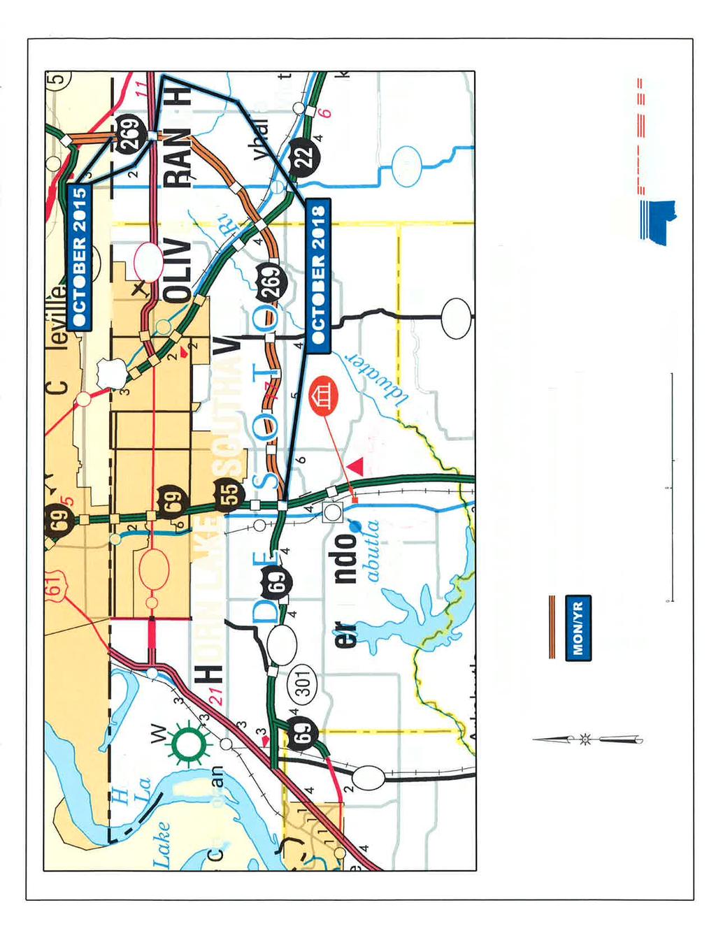
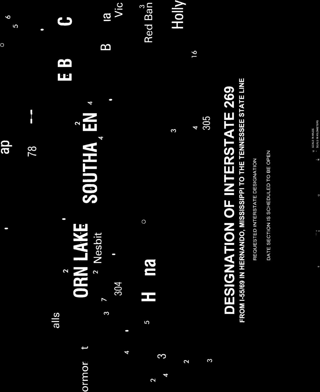
Transcription
1
2
3
4
5
6
7
8
9
10
11
12
13
14
15
16
17
18
19 U.S. 63 & U.S. 63 BUS US Route Number State Type Intersection Point to Point Accumulated Remarks 63 Arkansas Regular Mammoth Springs 0 0 Missouri State Line 63 Arkansas Regular Hardy Crosses U.S. 63 Bus. 63 Arkansas Regular Hardy 2 18 Crosses U.S. 63 Bus. Joins U.S. 62 and U.S Arkansas Business Hardy 0 0 Begins U.S Arkansas Business Hardy 1 1 Joins U.S Arkansas Business Hardy 1 2 Ends U.S Arkansas Regular Imboden Leaves U.S Arkansas Regular Portia (Southeast) Leaves U.S Arkansas Regular Hoxie 2 53 Crosses U.S. 63 Bus 63 Arkansas Regular Hoxie 3 56 Crosses U.S. 67 & U.S. 67 Bus. 63 Arkansas Regular Walnut Ridge 1 57 Crosses U.S Arkansas Regular Walnut Ridge 1 58 Crosses U.S. 63 Bus. 63 Arkansas Business Hoxie 0 0 Begins U.S Arkansas Business Hoxie 2 2 Joins U.S. 67 Bus. 63 Arkansas Business Hoxie 1 3 Leaves U.S. 67 Bus. 63 Arkansas Business Walnut Ridge 1 4 Crosses U.S Arkansas Business Walnut Ridge 1 5 Ends U.S Arkansas Regular Bono (North) Crosses U.S. 63 Bus. 63 Arkansas Regular Bono (South) 3 71 Crosses U.S. 63 Bus. 63 Arkansas Business Bono (North) 0 0 Begins U.S Arkansas Business Bono (South) 3 3 Ends U.S Arkansas Regular Jonesboro 8 79 Crosses U.S. 49, joins I Arkansas Regular Jonesboro 5 84 Crosses U.S. 63 Bus. 63 Arkansas Business Jonesboro 0 0 Begins U.S. 49/Hwy Arkansas Business Jonesboro 2 2 Ends U.S Arkansas Regular Marked Tree (West) Crosses U.S. 63 Bus. 63 Arkansas Regular Marked Tree (East) Crosses U.S. 63 Bus. 63 Arkansas Business Marked Tree (West) 0 0 Begins U.S. 63/Hwy Arkansas Business Marked Tree (East) 2 2 Ends U.S. 63/Hwy Arkansas Regular Turrell Joins I-55 and U.S Arkansas Regular Marion Crosses U.S Arkansas Regular West Memphis Joins I-40 and Leaves I-55/U.S. 61/I Arkansas Regular Brinkley Crosses U.S Arkansas Regular Hazen (North) Leaves I Arkansas Regular Hazen (South) Joins U.S Arkansas Regular Hazen (East) Leaves U.S Arkansas Regular Stuttgart Crosses U.S Arkansas Regular Stuttgart Joins U.S Arkansas Regular Stuttgart (West) Crosses U.S. 79 Bus. 63 Arkansas Regular Altheimer Crosses U.S. 79 Bus. 63 Arkansas Regular Altheimer Crosses U.S. 79 Bus.
20 63 Arkansas Regular Pine Bluff Crosses U.S. 65 Bus. 63 Arkansas Regular Pine Bluff Joins I Arkansas Regular Pine Bluff (South) Leaves I-530/Crosses U.S. 63 Bus. 63 Arkansas Business Pine Bluff 0 0 Begins U.S. 65 Bus. 63 Arkansas Business Pine Bluff 5 5 Ends I-530 and U.S Arkansas Regular Warren Crosses U.S. 63 Bus. 63 Arkansas Regular Warren Crosses U.S. 278 Bus. 63 Arkansas Regular Warren Crosses U.S. 63 Bus. 63 Arkansas Regular Warren (South) Crosses U.S Arkansas Business Warren 0 0 Begins U.S Arkansas Business Warren 1 1 Crosses U.S. 278 Bus. 63 Arkansas Business Warren 1 2 Ends U.S Arkansas Regular Hermitage Crosses U.S. 63 Bus. 63 Arkansas Regular Hermitage Crosses U.S. 63 Bus. 63 Arkansas Business Hermitage 0 0 Begins U.S Arkansas Business Hermitage 1 1 Ends U.S Arkansas Regular El Dorado Joins U.S Arkansas Regular El Dorado Crosses U.S. 82 Bus. 63 Arkansas Regular El Dorado (South) Crosses U.S Arkansas Regular Junction City Louisiana State Line
21 American Association of State Highway and Transportation Officials An Application from the State Highway or Transportation Department of North Carolina for: Elimination of a U.S. (Interstate) Route AASHTO Use Only Establishment of a U.S. (Interstate) Route Future I-36 Action taken by SCOH: Extension of a U.S. (Interstate)Route Relocation of a U.S. (Interstate) Route Establishment of a U.S. Alternate Route Establishment of a Temporary U.S. Route **Recognition of a Business Route on U.S. (Interstate) Route **Recognition of a By-Pass Route on U.S. Route Between I-40 in Garner, NC and Port of Morehead City, NC The following states or states are involved: North Carolina ** Recognition of A local vicinity map needed on page 3. On page 6 a short statement to the effect that there are no deficiencies on proposed routing, if true, will suffice. If there are deficiencies, they should be indicated in accordance with page 5 instructions. All applications requesting Interstate establishment or changes are subject to concurrence and approval by the FHWA DATE SUBMITTED: April 18, 2016 SUBMIT APPLICATION ELECTRONICALLY TO usroutes@aashto.org *Bike Routes: this form is not applicable for US Bicycle Route System
22 The purpose of the United States (U.S.) Numbered Highway System is to facilitate travel on the main interstate highways, over the shortest routes and the best available roads. A route should form continuity of available facilities through two or more states that accommodate the most important and heaviest motor traffic flow in the area. The routes comprising the National System of Interstate and Defense Highways will be marked with its own distinctive route marker shield and will have a numbering system that is separate and apart from the U.S. Numbered Highway System. For the convenience of the motorist, there must be continuity and a uniform pattern of marking and numbering these Interstate routes without regard to state lines. The U.S. Numbered System was established in 1926 and the Interstate Numbered System was established in Both have reached the period of review, revision, and consolidation. They now need perfecting rather than expansion. Therefore, any proposed alteration in the established systems should be extremely meritorious and thoroughly, though concisely, explained in order that the Special Committee on U.S. Route Numbering and the Standing Committee on Highways of the Association may give prompt and proper consideration to each and every request made by a member department. Explanation and Reasons for the Request: (Keep concise and pertinent.) This application is to establish the proposed number of I-36 along US 70 from I-40 to the Port at Morehead City. This proposed route was Congressionally designated as a high priority future Interstate corridor on the National Highway System, as identified in the FAST Act, which was signed into federal law December 4, The FAST Act provided inclusion of this portion of US 70 in North Carolina by amending Section 1105(c) of the Intermodal Surface Transportation Efficiency Act of The proposed corridor will provide connectivity to Seymour Johnson and Cherry Point military bases, and is also in close proximity to Camp Lejeune. Additionally, the proposed corridor ends at an international multimodal port in Morehead City. As individual portions of the proposed alignment are constructed or upgraded to interstate standards, separate AASHTO applications requesting the addition of those portions to the interstate system will be submitted for review. Date facility available to traffic Currently Available Does the petition propose a new routing over a portion of an existing U.S. Route? Yes If so, where? US 70, US 70 Bypass in eastern North Carolina. Does the petition propose a new routing over a portion of an existing Interstate Route? No If so, where? 2

23 Map of state, or portion thereof, indicating proposed addition or change in the U.S. Numbered or Interstate Numbered System: Send your PDF color map to or with this application. (Indicate termini and control points on the map for the route, and number them in sequence. Use the same numbers in column 1 tabulation, page 6, when listing mileage. Towns, cities, major highway intersections and state lines to be used as control points. The top of column 1, page 6, will be one terminus, and column 1 will give the log of the route as needed to describe the route in the Association publication U.S. Numbered Highways if the application is approved by the Standing Committee on Highways.) 3
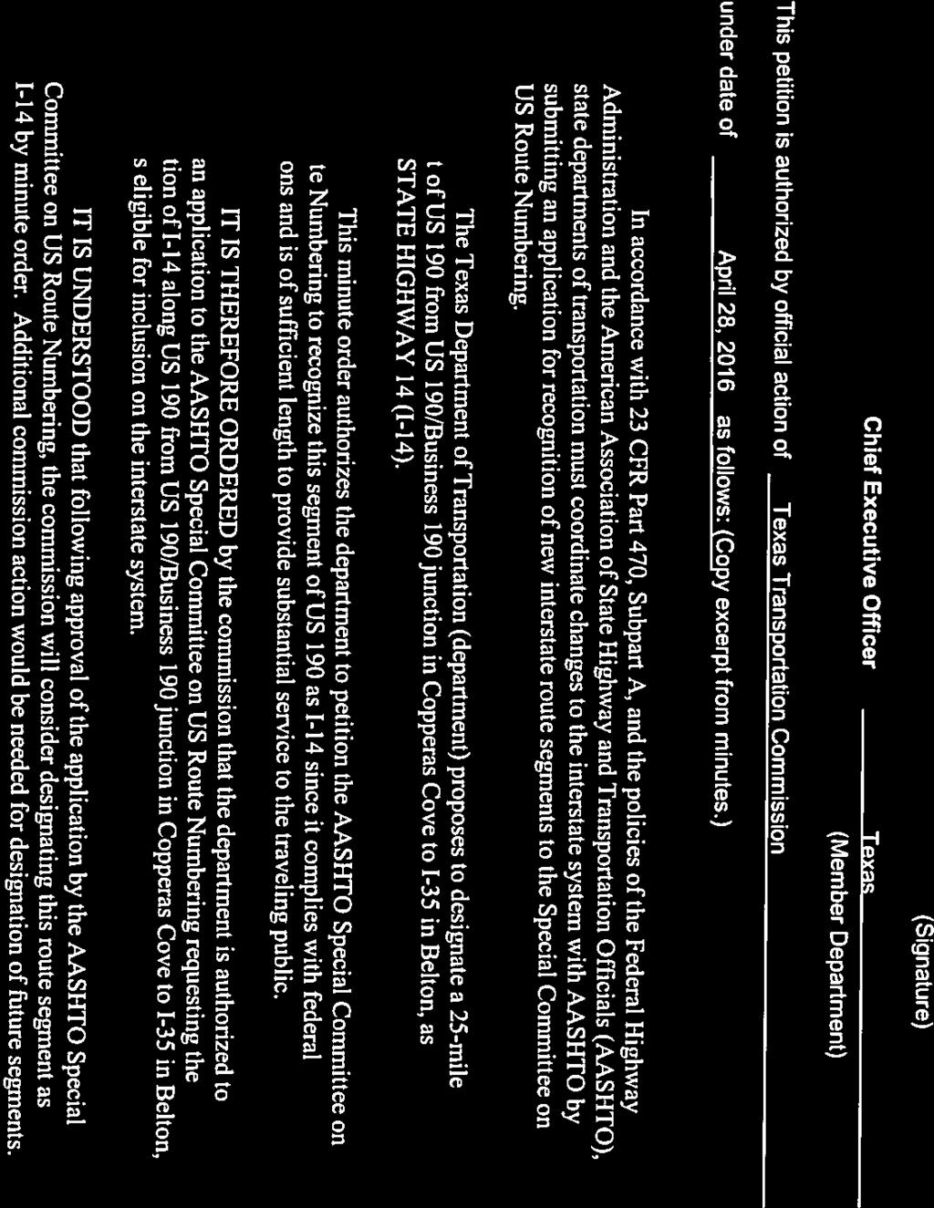
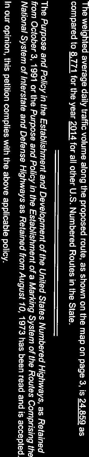
24 The State agrees and pledges its good faith that it will not erect, remove, or change any U.S. or Interstate Route Markers on any road without the authorization, consent, or approval of the Standing Committee on Highways of the American Association of State Highway and Transportation Officials, not withstanding the fact that the changes proposed are entirely within this State. The weighted average daily traffic volume along the proposed route, as shown on the map on page 3, is 23,000 as compared to 47,800 for the year 2013 for the remaining portions of U.S. Numbered Routes in the State. The Purpose and Policy in the Establishment and Development of the United States Numbered Highways, as Retained from October 3, 1991 or the Purpose and Policy in the Establishment of a Marking System of the Routes Comprising the National System of Interstate and Defense Highways as Retained from August 10, 1973 has been read and is accepted. In our opinion, this petition complies with the above applicable policy. (Signature) Chief Executive Officer (Member Department) This petition is authorized by official action of under date of as follows: (Copy excerpt from minutes.) A letter from your Chief Executive Officer with the CEO s signature is sufficient when submitting your application, if you choose not to include the signature on this form. 4
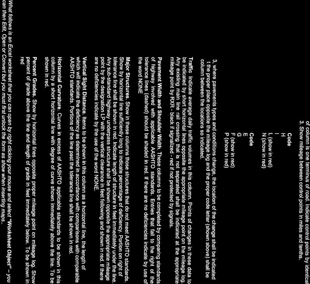
25 Instructions for Preparation of Page 6 Column 1: Control Points and Mileage. Top of column is one terminus of road. Indicate control points by identical number as shown on map on page 3. Show mileage between control points in miles and tenths. Column 2: Pavement Type. Code High type, heavy duty H Intermediate type I Low type, dustless L (show in red) Not paved N (show in red) Column 3: Pavement Condition Code Excellent E Good G Fair F (show in red) Poor P (show in red) NOTE: In columns 2 and 3, where pavements types and conditions change, the location of the change shall be indicated by a short horizontal line at the proper place opposite the mileage log and the proper code letter (shown above) shall be entered in the respective column between the locations so indicated. Column 4: Columns 5 & 6 Columns 7 & 8 Column 9: Column 10: Column 11 Traffic. Indicate average daily traffic volumes in this column. Points of changes in these data to be indicated by short horizontal lines opposite the appropriate mileage point on the mileage log. Any existing main line rail crossing that is not separated shall be indicated at the appropriate mileage point by RXR - black if signalized - red if not protected by signals. Pavement Width and Shoulder Width. These columns to be completed by comparing standards of highway involved with applicable AASHTO standards. Entries that fall to the right of the tolerance lines (dashed) should be shaded in red. If there are no deficiencies indicate by use of the word NONE. Major Structures. Show in these columns those structures that do not meet AASHTO standards. Show by horizontal line sufficiently long to indicate percentage of deficiency. Portion on right of tolerance line shall be shown in red. Indicate length of structure in feet immediately under the line. Any sub-standard highway underpass structure shall be shown opposite the appropriate mileage point by the designation LP with the vertical clearance in feet following and shown in red. If there are no deficiencies indicate by the use of the word NONE. Vertical Sight Distance. Items to be shown in this column as a horizontal line, the length of which will indicate the deficiency as determined in accordance with comparisons with comparable AASHTO standards. Portions of the line past the tolerance line shall be shown in red. Horizontal Curvature. Curves in excess of AASHTO applicable standards to be shown in this column by a short horizontal line with degree of curve shown immediately above the line. To be shown in red. Percent Grades. Show by horizontal lines opposite proper mileage point on mileage log. Show percent of grade above the line and length of grade in feet immediately below. To be shown in red. What follows is an Excel worksheet that you can open by right clicking your mouse and select Worksheet Object you can then Edit, Open or Convert but you must first unlock the form as show when inserting maps.. 5
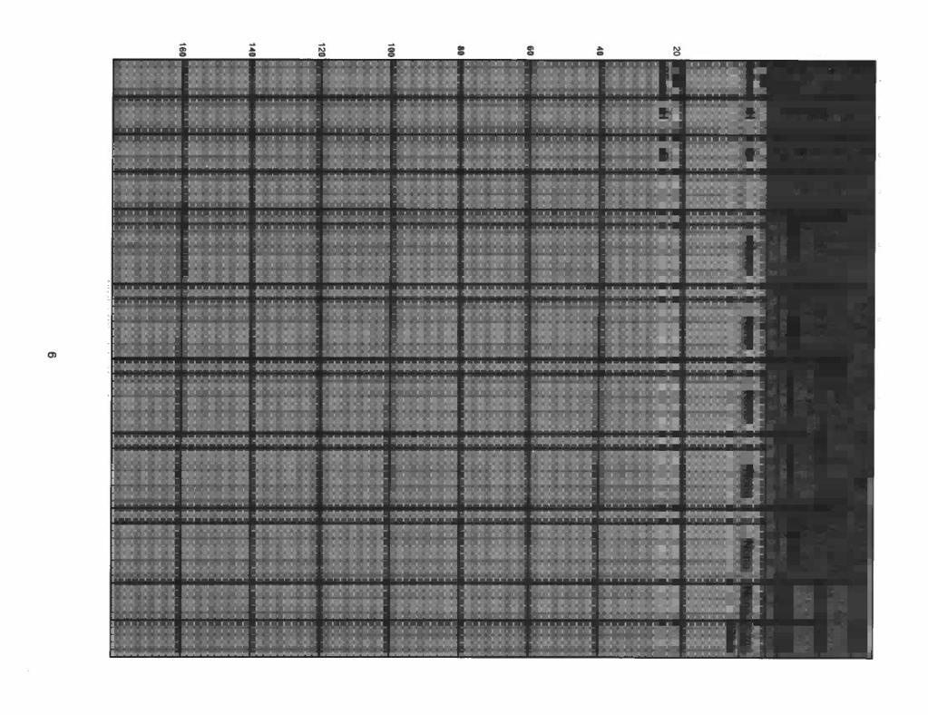
26 Mileage Control Points and Mileage Pavement Type Pavement Condition Traffic ADT Comparison to Applicable AASHTO Design Standards Pavement Width Deficiency Shoulder Width Deficiency Roadway Width Deficiency Percent Percent Percent Major Structures H - Loading Deficiency Percent Vertical Sight Distance Deficiency Percent Show When In Excess of Standard Horizontal Curvature Degree Percent Grade Length Individual portions of the corridor will be upgraded or constructed to acceptable AASHTO standards. Separate applications will be provided for those portions as they are completed and will include specific design data
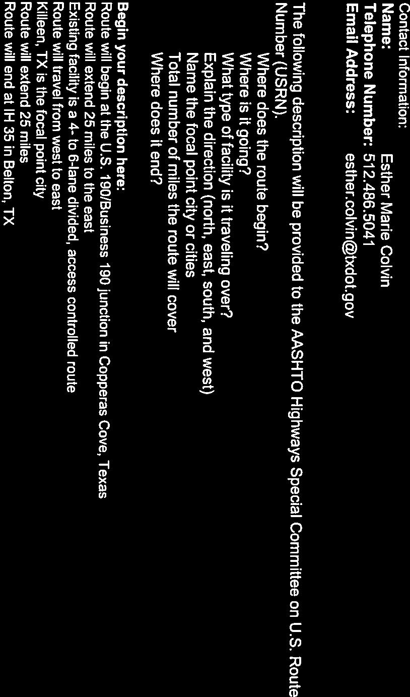
27 Contact Information: Renee B. Roach, P.E (phone) (fax) The following description will be provided to the AASHTO Highways Special Committee on U.S. Route Number (USRN). Where does the route begin? Where is it going? What type of facility is it traveling over? Explain the direction (north, east, south, and west) Name the focal point city or cities Total number of miles the route will cover Where does it end? Begin your description here: The route begins at existing I-40 in Garner. The route is going generally southeast, through Clayton, Smithfield, Selma, Goldsboro, Kinston, New Bern, and Havelock. The route is travelling along a multi-lane facility with varying levels of access control. The route is generally travelling southeast. The focal points are the Town of Garner, Town of Clayton, Town of Smithfield, Town of Selma, City of Goldsboro, City of Kinston, City of New Bern, City of Havelock and the Town of Morehead City. This route will cover approximately miles. The route ends at the international multimodal Port of Morehead City. 7
28 Revised Log for the U.S. Route Numbering Database: Revised database log not applicable due to route being new Interstate. 8
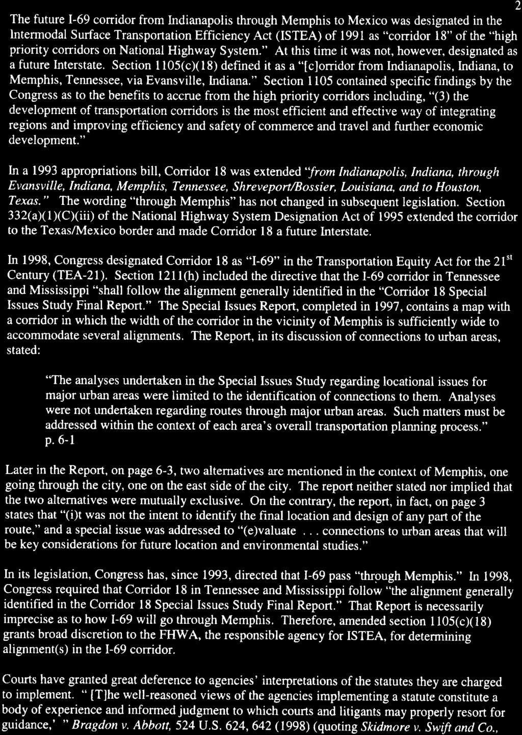
29 Future I-36 Corridor Durham Apex Holly Springs Fuquay- Varina 401 Cary Raleigh 40 Garner 540 W A K E Knightdale Clayton 70 Archer Lodge Zebulon Wilson's Mills Smithfield 64 Selma Wilson 117 Rocky Mount G R E E N E 258 Farmville 13 Greenville Winterville P I T T 17 Washington Chocowinity 64 Created: 2/17/2016 Revised: 3/8/ Lillington Benson 95 J O H N S T O N 795 Goldsboro Snow Hill Ayden Grifton B E A U F O R T Dunn 13 W A Y N E Walnut Creek 70 L E N O I R Kinston C R A V E N 301 Mount Olive 17 P A M L I C O Fayetteville 95 Clinton Warsaw D U P L I N 258 J O N E S New Bern Trent Woods 70 Grantsboro Havelock Minnesott Beach C A R T E R E T Jacksonville 701 Wallace O N S L O W Swansboro Peletier Emerald Isle Bogue Newport Pine Knoll Shores Morehead City Atlantic Beach Beaufort Bladenboro Future I-36 Corridor (Approx. Distance = miles) Miles
30
31
 Route Future I-89 Action taken by SCOH: Extension of a U.S. (Interstate)Route Relocation of a U.S. (Interstate) Route Establishment of a U.S. Alternate Route Establishment of a Temporary U.")

32 American Association of State Highway and Transportation Officials An Application from the State Highway or Transportation Department of North Carolina for: Elimination of a U.S. (Interstate) Route AASHTO Use Only Establishment of a U.S. (Interstate) Route Future I-89 Action taken by SCOH: Extension of a U.S. (Interstate)Route Relocation of a U.S. (Interstate) Route Establishment of a U.S. Alternate Route Establishment of a Temporary U.S. Route **Recognition of a Business Route on U.S. (Interstate) Route **Recognition of a By-Pass Route on U.S. Route Between I-40 in Raleigh, NC and North Carolina/Virginia State Line The following states or states are involved: North Carolina Virginia ** Recognition of A local vicinity map needed on page 3. On page 6 a short statement to the effect that there are no deficiencies on proposed routing, if true, will suffice. If there are deficiencies, they should be indicated in accordance with page 5 instructions. All applications requesting Interstate establishment or changes are subject to concurrence and approval by the FHWA DATE SUBMITTED: April 18, 2016 SUBMIT APPLICATION ELECTRONICALLY TO usroutes@aashto.org *Bike Routes: this form is not applicable for US Bicycle Route System
33 The purpose of the United States (U.S.) Numbered Highway System is to facilitate travel on the main interstate highways, over the shortest routes and the best available roads. A route should form continuity of available facilities through two or more states that accommodate the most important and heaviest motor traffic flow in the area. The routes comprising the National System of Interstate and Defense Highways will be marked with its own distinctive route marker shield and will have a numbering system that is separate and apart from the U.S. Numbered Highway System. For the convenience of the motorist, there must be continuity and a uniform pattern of marking and numbering these Interstate routes without regard to state lines. The U.S. Numbered System was established in 1926 and the Interstate Numbered System was established in Both have reached the period of review, revision, and consolidation. They now need perfecting rather than expansion. Therefore, any proposed alteration in the established systems should be extremely meritorious and thoroughly, though concisely, explained in order that the Special Committee on U.S. Route Numbering and the Standing Committee on Highways of the Association may give prompt and proper consideration to each and every request made by a member department. Explanation and Reasons for the Request: (Keep concise and pertinent.) This application is to establish the proposed number of I-89 within the state of North Carolina. This proposed route was Congressionally designated as a high priority future interstate corridor on the National Highway System, as identified in the FAST Act, which was signed into federal law December 4, The FAST Act provided inclusion of this corridor in North Carolina by amending Section 1105(c) of the Intermodal Surface Transportation Efficiency Act of The ultimate ending point for this high priority corridor is Norfolk, Virginia. The State of North Carolina has coordinated with the Commonwealth of Virginia and they concur with the proposed I-89 route number. While the I-89 route designation is utilized in the states of New Hampshire and Vermont, it is requested due to the increasing difficulty in identifying an Interstate number that meets the criteria and is not currently in use. Confusion between other occurrences of the I-89 route is unlikely due to a significant separation of the Interstate Routes. Additionally, adding another current Interstate route that is non-continuous is not a unique occurrence. As individual portions of the proposed alignment are constructed or upgraded to interstate standards, separate AASHTO applications requesting the addition of those portions to the interstate system will be submitted for review. Date facility available to traffic Currently Available Does the petition propose a new routing over a portion of an existing U.S. Route? Yes If so, where? US 64, US 264, US 13, US 17, US 17 Bypass, and US 158 in northeastern North Carolina. Does the petition propose a new routing over a portion of an existing Interstate Route? Yes If so, where? I-440 southeast of the City of Raleigh and I-495 northeast of the City of Raleigh 2

34 Map of state, or portion thereof, indicating proposed addition or change in the U.S. Numbered or Interstate Numbered System: Send your PDF color map to or with this application. (Indicate termini and control points on the map for the route, and number them in sequence. Use the same numbers in column 1 tabulation, page 6, when listing mileage. Towns, cities, major highway intersections and state lines to be used as control points. The top of column 1, page 6, will be one terminus, and column 1 will give the log of the route as needed to describe the route in the Association publication U.S. Numbered Highways if the application is approved by the Standing Committee on Highways.) 3
35 The State agrees and pledges its good faith that it will not erect, remove, or change any U.S. or Interstate Route Markers on any road without the authorization, consent, or approval of the Standing Committee on Highways of the American Association of State Highway and Transportation Officials, not withstanding the fact that the changes proposed are entirely within this State. The weighted average daily traffic volume along the proposed route, as shown on the map on page 3, is 21,800 as compared to 47,800 for the year 2013 for the remaining portions of U.S. Numbered Routes in the State. The Purpose and Policy in the Establishment and Development of the United States Numbered Highways, as Retained from October 3, 1991 or the Purpose and Policy in the Establishment of a Marking System of the Routes Comprising the National System of Interstate and Defense Highways as Retained from August 10, 1973 has been read and is accepted. In our opinion, this petition complies with the above applicable policy. Chief Executive Officer (Member Department) This petition is authorized by official action of under date of as follows: (Copy excerpt from minutes.) A letter from your Chief Executive Officer with the CEO s signature is sufficient when submitting your application, if you choose not to include the signature on this form. 4
36 Instructions for Preparation of Page 6 Column 1: Control Points and Mileage. Top of column is one terminus of road. Indicate control points by identical number as shown on map on page 3. Show mileage between control points in miles and tenths. Column 2: Pavement Type. Code High type, heavy duty H Intermediate type I Low type, dustless L (show in red) Not paved N (show in red) Column 3: Pavement Condition Code Excellent E Good G Fair F (show in red) Poor P (show in red) NOTE: In columns 2 and 3, where pavements types and conditions change, the location of the change shall be indicated by a short horizontal line at the proper place opposite the mileage log and the proper code letter (shown above) shall be entered in the respective column between the locations so indicated. Column 4: Columns 5 & 6 Columns 7 & 8 Column 9: Column 10: Column 11 Traffic. Indicate average daily traffic volumes in this column. Points of changes in these data to be indicated by short horizontal lines opposite the appropriate mileage point on the mileage log. Any existing main line rail crossing that is not separated shall be indicated at the appropriate mileage point by RXR - black if signalized - red if not protected by signals. Pavement Width and Shoulder Width. These columns to be completed by comparing standards of highway involved with applicable AASHTO standards. Entries that fall to the right of the tolerance lines (dashed) should be shaded in red. If there are no deficiencies indicate by use of the word NONE. Major Structures. Show in these columns those structures that do not meet AASHTO standards. Show by horizontal line sufficiently long to indicate percentage of deficiency. Portion on right of tolerance line shall be shown in red. Indicate length of structure in feet immediately under the line. Any sub-standard highway underpass structure shall be shown opposite the appropriate mileage point by the designation LP with the vertical clearance in feet following and shown in red. If there are no deficiencies indicate by the use of the word NONE. Vertical Sight Distance. Items to be shown in this column as a horizontal line, the length of which will indicate the deficiency as determined in accordance with comparisons with comparable AASHTO standards. Portions of the line past the tolerance line shall be shown in red. Horizontal Curvature. Curves in excess of AASHTO applicable standards to be shown in this column by a short horizontal line with degree of curve shown immediately above the line. To be shown in red. Percent Grades. Show by horizontal lines opposite proper mileage point on mileage log. Show percent of grade above the line and length of grade in feet immediately below. To be shown in red. What follows is an Excel worksheet that you can open by right clicking your mouse and select Worksheet Object you can then Edit, Open or Convert but you must first unlock the form as show when inserting maps.. 5
37 Mileage Control Points and Mileage Pavement Type Pavement Condition Traffic ADT Comparison to Applicable AASHTO Design Standards Pavement Width Deficiency Shoulder Width Deficiency Percent Percent Percent Major Structures Roadway Width Deficiency H - Loading Deficiency Percent Vertical Sight Distance Deficiency Percent Show When In Excess of Standard Horizontal Curvature Degree Percent Grade Length Individual portions of the corridor will be upgraded or constructed to acceptable AASHTO standards. Separate applications will be provided for those portions as they are completed and will include specific design data
38 Contact Information: Renee B. Roach, P.E (phone) (fax) The following description will be provided to the AASHTO Highways Special Committee on U.S. Route Number (USRN). Where does the route begin? Where is it going? What type of facility is it traveling over? Explain the direction (north, east, south, and west) Name the focal point city or cities Total number of miles the route will cover Where does it end? Begin your description here: The route begins at existing I-440 in Raleigh. The route is going generally north and east, through Rocky Mount, Williamston, and Elizabeth City in North Carolina. The route is travelling along a multi-lane facility with varying levels of access control. The route is generally travelling north and east. The focal points are the City of Raleigh, the City of Rocky Mount, Town of Williamston, Town of Windsor, and City of Elizabeth City. This route will cover approximately miles. The route ends north of Elizabeth City, at the North Carolina/Virginia state line. 7
39 Revised Log for the U.S. Route Numbering Database: Revised database log not applicable due to route being new Interstate. 8
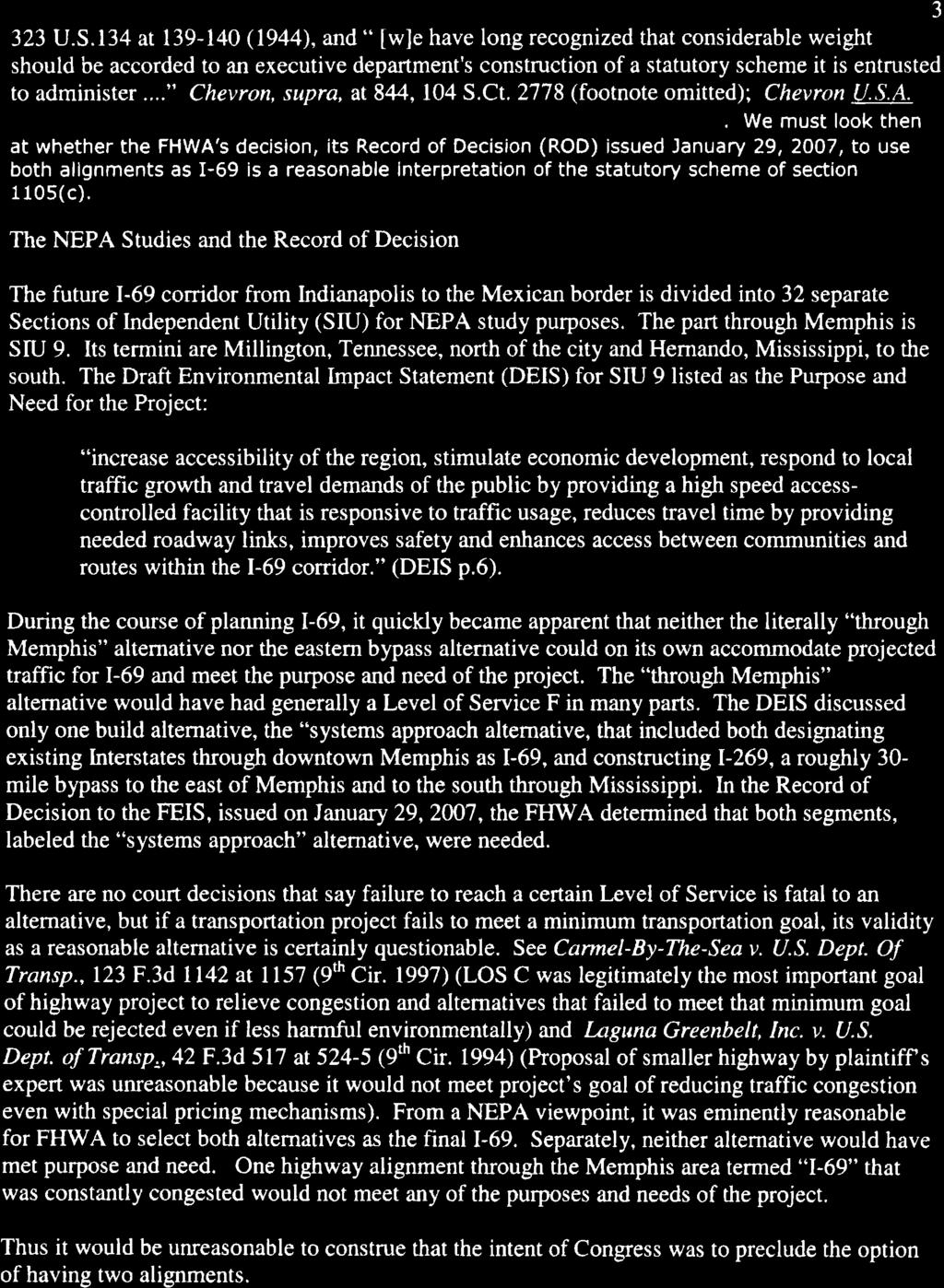
40 Future I-89 Corridor Created: 3/8/2016 Suffolk Chesapeake Franklin V I R G I N I A Oxford Henderson N O R T H C A R O L I N A N O R T H A M P T O N 13 H E R T F O R D G A T E S 158 Elizabeth City C U R R I T U C K C A M D E N H A L I F A X P A S Q U O T A N K D U R H A M Butner 85 Fuquay- Varina Creedmoor Franklinton Youngsville Louisburg F R A N K L I N N A S H Red Oak Dortches Durham Wake Nashville Rocky Forest Mount Rolesville Tarboro M A R T I N Raleigh 64 W A K E 70 Williamston Zebulon Morrisville Wendell 264 W I L S O N Plymouth W A S H I N G T O N Knightdale Cary Apex J O H N S T O N Wilson Archer Garner Lodge Holly Springs Clayton P I T T Walnut E D G E C O M B E 258 Greenville Future I-89 Corridor (Approx. Distance = miles) 17 B E R T I E Windsor 17 C H O W A N Edenton P E R Q U I M A N S T Y R R E L L Miles
41
42
 Route Extension of a U.S. (Interstate) Route I-269 Relocation of a U.S. (Interstate) Route AASHTO Use Only Action taken by SCOH: Establishment of a U.S. Alternate Route Establishment of a Temporary U.")

43 American Association of State Highway and Transportation Officials An Application from the State Highway or Transportation Department of Tennessee for: Elimination of a U.S. (Interstate) Route Establishment of a U.S. (Interstate) Route Extension of a U.S. (Interstate) Route I-269 Relocation of a U.S. (Interstate) Route AASHTO Use Only Action taken by SCOH: Establishment of a U.S. Alternate Route Establishment of a Temporary U.S. Route **Recognition of a Business Route on U.S. (Interstate) Route **Recognition of a By-Pass Route on U.S. Route Between Mississippi State Line and existing Interstate 40 in Tennessee The following states or states are involved: Tennessee ** Recognition of A local vicinity map needed on page 3. On page 6 a short statement to the effect that there are no deficiencies on proposed routing, if true, will suffice. If there are deficiencies, they should be indicated in accordance with page 5 instructions. All applications requesting Interstate establishment or changes are subject to concurrence and approval by the FHWA DATE SUBMITTED: SUBMIT APPLICATION ELECTRONICALLY TO usroutes@aashto.org *Bike Routes: this form is not applicable for US Bicycle Route System
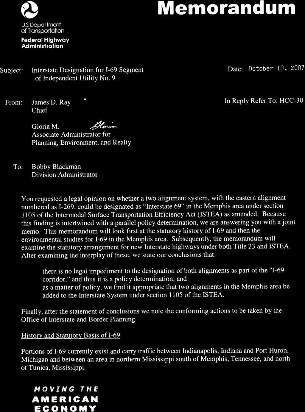
44 The purpose of the United States (U.S.) Numbered Highway System is to facilitate travel on the main interstate highways, over the shortest routes and the best available roads. A route should form continuity of available facilities through two or more states that accommodate the most important and heaviest motor traffic flow in the area. The routes comprising the National System of Interstate and Defense Highways will be marked with its own distinctive route marker shield and will have a numbering system that is separate and apart from the U.S. Numbered Highway System. For the convenience of the motorist, there must be continuity and a uniform pattern of marking and numbering these Interstate routes without regard to state lines. The U.S. Numbered System was established in 1926 and the Interstate Numbered System was established in Both have reached the period of review, revision, and consolidation. They now need perfecting rather than expansion. Therefore, any proposed alteration in the established systems should be extremely meritorious and thoroughly, though concisely, explained in order that the Special Committee on U.S. Route Numbering and the Standing Committee on Highways of the Association may give prompt and proper consideration to each and every request made by a member department. Explanation and Reasons for the Request: (Keep concise and pertinent.) Section 1105 of the Intermodal Surface Transportation Efficiency Act (ISTEA) of 1991 designated several high priority corridors on the National Highway System including Corridor 18 from Indianapolis, Indiana to Memphis, Tennessee. Section 332 of the National Highway System Designation Act of 1995 extended Corridor 18 to the border between the United States and Mexico and included Corridor 18 on the Interstate Highway System. In 1998, Congress designated Corridor 18 as I-69 in the Transportation Equity Act for the 21 st Century (TEA-21). For the NEPA study purposes, I-69 was divided into 32 separate Sections of Independent Utility (SIU). The part through Memphis is SIU 9. To meet the project purpose and need, SIU 9 included alignments through Memphis and east of Memphis. An October 2007 legal opinion by the FHWA concluded the SIU 9 corridor designated as a future Interstate may include both the alignment through Memphis (future I-69) and east of Memphis (I-269). The Tennessee Department of Transportation (TDOT) has conducted a study of the mile four lane divided full access controlled route from the northern terminus of existing I-269 at the Mississippi State Line to Interstate 40 in Memphis. The purpose of the review was to determine if it met the Interstate designation criteria in 23 CFR Part 470, Appendix B. Based on the plans and field review of the as-built roadway, it has been determined that the segment meets the Interstate design criteria published by AASHTO. No substandard elements were identified that would require a design exception. In accordance with the enacted Congressional legislation and 23 CFR Part 470, Appendix B, the TDOT is making a request to designate and sign the four lane divided full access controlled route between the Mississippi State Line and Interstate 40 in Memphis as I-269. Date facility available to traffic The existing facility is currently open to traffic Does the petition propose a new routing over a portion of an existing U.S. Route? No If so, where? N/A Does the petition propose a new routing over a portion of an existing Interstate Route? No If so, where? N/A 2
45 Map of state, or portion thereof, indicating proposed addition or change in the U.S. Numbered or Interstate Numbered System: Send your PDF color map to or with this application. (Indicate termini and control points on the map for the route, and number them in sequence. Use the same numbers in column 1 tabulation, page 6, when listing mileage. Towns, cities, major highway intersections and state lines to be used as control points. The top of column 1, page 6, will be one terminus, and column 1 will give the log of the route as needed to describe the route in the Association publication U.S. Numbered Highways if the application is approved by the Standing Committee on Highways.) 3

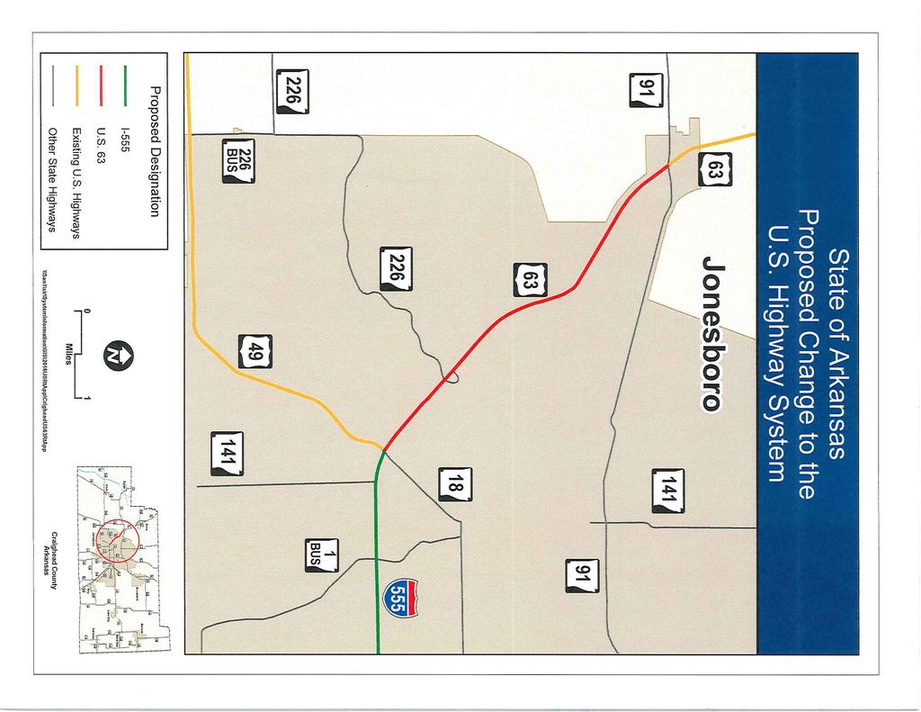
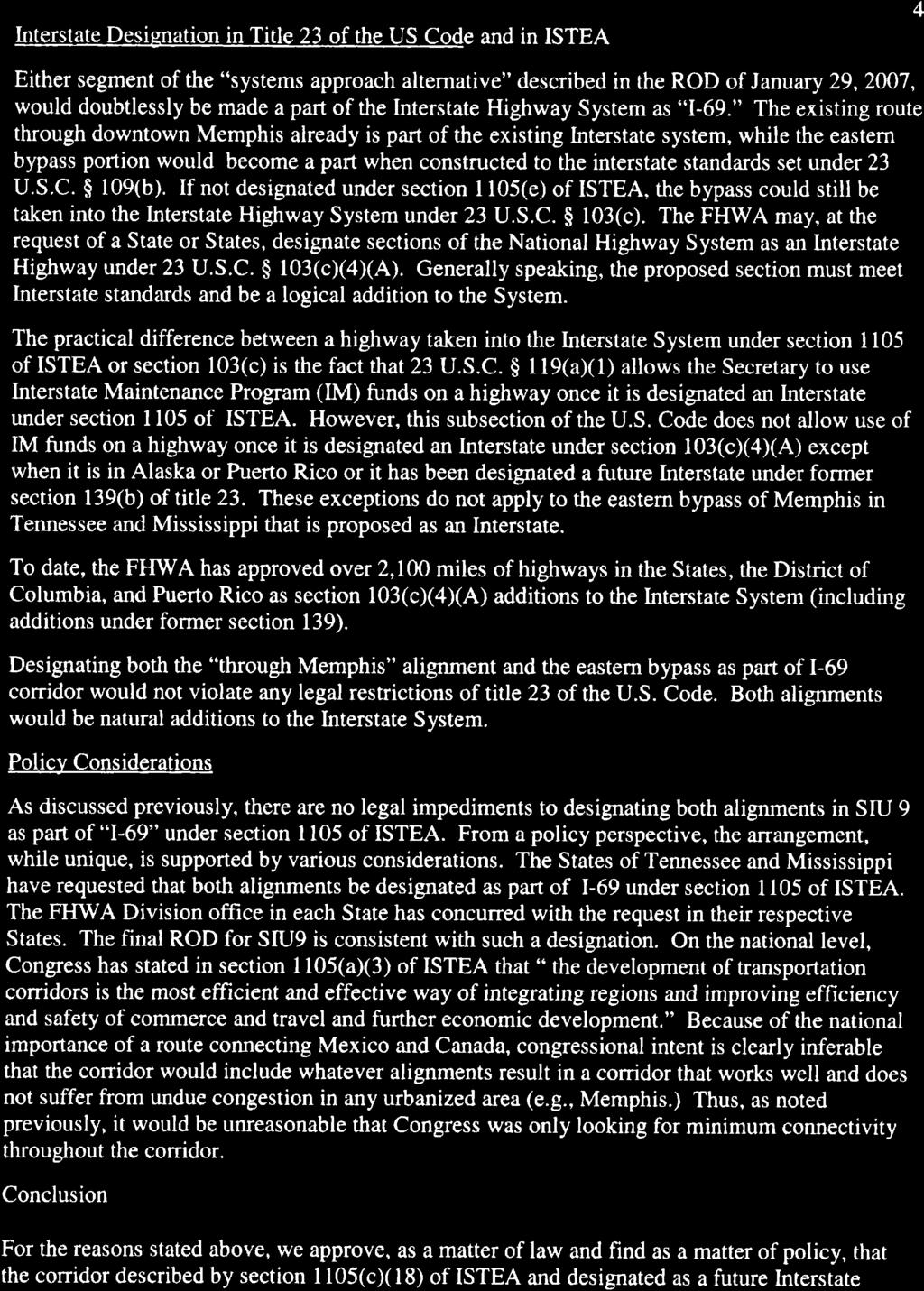
46 % 204 % 204 % ³ Bartlett 1 ³ Lakeland 79 70!"#$ ³ 5 ³! 1 Arlington 64 Proposed!"#$ 269! 4 15 ³ SECTION 4 From SR-15 to I-40 14,168 AADT % 196 Oakland % % 23 WOLF RIVER % 177 Memphis S h e l b y SECTION 3 From N. Monterey Rd. to SR-15 15,448 AADT! 3 F a y e t t e % 193 «02!"#$ ³ SECTION 2 From North of SR-57 to N. Monterey Rd. 15,500 AADT % 175 Germantown Collierville ³ SECTION 1 From Mississippi State Line to North of SR-57 13,620 AADT % ³ 2 Proposed!"#$ 269!! 72 1 % 196 Piperton WOLF RIVER 57 ³ Rossville % 194 M I S S I S S I P P I «305 « Ü Proposed Proposed Interstate 269!"#$ 269 «304 «178 78! Control Points Prepared by Tennessee Dept. of Transportation Long Range Planning Division Data Visualization Office Date: 3/1/2016

47
48 Instructions for Preparation of Page 6 Column 1: Control Points and Mileage. Top of column is one terminus of road. Indicate control points by identical number as shown on map on page 3. Show mileage between control points in miles and tenths. Column 2: Pavement Type. Code High type, heavy duty H Intermediate type I Low type, dustless L (show in red) Not paved N (show in red) Column 3: Pavement Condition Code Excellent E Good G Fair F (show in red) Poor P (show in red) NOTE: In columns 2 and 3, where pavements types and conditions change, the location of the change shall be indicated by a short horizontal line at the proper place opposite the mileage log and the proper code letter (shown above) shall be entered in the respective column between the locations so indicated. Column 4: Columns 5 & 6 Columns 7 & 8 Column 9: Column 10: Column 11 Traffic. Indicate average daily traffic volumes in this column. Points of changes in these data to be indicated by short horizontal lines opposite the appropriate mileage point on the mileage log. Any existing main line rail crossing that is not separated shall be indicated at the appropriate mileage point by RXR - black if signalized - red if not protected by signals. Pavement Width and Shoulder Width. These columns to be completed by comparing standards of highway involved with applicable AASHTO standards. Entries that fall to the right of the tolerance lines (dashed) should be shaded in red. If there are no deficiencies indicate by use of the word NONE. Major Structures. Show in these columns those structures that do not meet AASHTO standards. Show by horizontal line sufficiently long to indicate percentage of deficiency. Portion on right of tolerance line shall be shown in red. Indicate length of structure in feet immediately under the line. Any sub-standard highway underpass structure shall be shown opposite the appropriate mileage point by the designation LP with the vertical clearance in feet following and shown in red. If there are no deficiencies indicate by the use of the word NONE. Vertical Sight Distance. Items to be shown in this column as a horizontal line, the length of which will indicate the deficiency as determined in accordance with comparisons with comparable AASHTO standards. Portions of the line past the tolerance line shall be shown in red. Horizontal Curvature. Curves in excess of AASHTO applicable standards to be shown in this column by a short horizontal line with degree of curve shown immediately above the line. To be shown in red. Percent Grades. Show by horizontal lines opposite proper mileage point on mileage log. Show percent of grade above the line and length of grade in feet immediately below. To be shown in red. What follows is an Excel worksheet that you can open by right clicking your mouse and select Worksheet Object you can then Edit, Open or Convert but you must first unlock the form as show when inserting maps.. 5
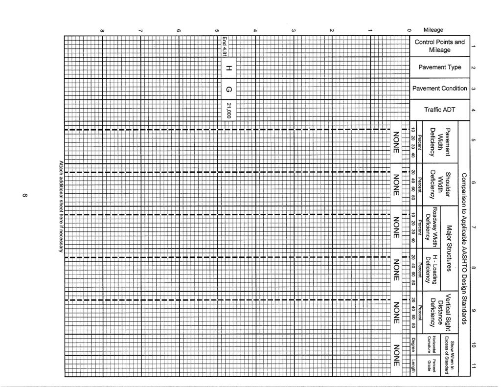
49 Mileage Control Points and Mileage Pavement Type Pavement Condition 1 H E Traffic ADT Pavement Width Deficiency Comparison to Applicable AASHTO Design Standards Shoulder Width Deficiency Roadway Width Deficiency Percent Percent Percent Percent Major Structures NONE H - Loading Deficiency Vertical Sight Distance Deficiency Percent Show When In Excess of Standard Horizontal Curvature Percent Grade Degree Length H E 13,620 NONE H E 15,500 NONE H E 15,448 NONE H E 14,168 NONE
50 Contact Information: Tanisha Hall, Director, Long Range Planning Division, Tennessee Department of Transportation (615) The following description will be provided to the AASHTO Highways Special Committee on U. S. Route Number (USRN). Where does the route begin? Where is it going? What type of facility is it traveling over? Explain the direction (north, east, south, and west) Name the focal point city or cities Total number of miles the route will cover Where does it end? Begin your description here: The route will begin at the northern terminus of I-269 at the Mississippi / Tennessee State line The route will extend I-269 to Interstate 40 in Memphis, Tennessee The existing facility is a 4 lane divided route with full access control The route will extend I-269 from south to north Memphis is the focal point city The route segment is miles long The route will end at existing Interstate 40 in Memphis 7
51 Interstate 269 Extension from the Mississippi State Line To Interstate 40 in Tennessee ( Supporting Correspondence for AASHTO Route Numbering Committee) Attachment A An E mail to TDOT from FHWA Tennessee Division describing steps required to designate existing Tennessee State Route 385 as Interstate 269 Attachment B An October 10, 2007 Policy memo from the FHWA indicating the corridor described by section 1105(c)(18) of ISTEA, as amended, could include both a through Memphis alignment (I 69) and an Eastern alignment (I 269) Attachment C A February 2016 field review report of existing Tennessee State Route 385 concluding the project, as designed and built, meets the existing Interstate Design Standards Attachment D A May 14, 2015 FHWA letter from the FHWA Mississippi Division recommending I 269 designation for State Route 304 in Mississippi to the Tennessee State Line
52 Jeff C. Jones From: Sent: Friday, January 15, :23 PM To: Jeff C. Jones Cc: Jason Baker; Paul Degges; Lyndsay Botts; Subject: RE: Interstate Designation Procedures / I-269 Jeff, We ve researched the steps necessary for TDOT to follow to designate I 269 as a Congressionally designated future Interstate corridor. 23 CFR (e) states that future Interstate routes can only be signed or marked if the highway is constructed to Interstate design standards and designated as part of the Interstate System. Appendix B to 23 CFR Part 470 describes the process for designating the Highway Priority Corridors under ISTEA and the NHS Act as part of the Interstate system: The State DOT Secretary (or equivalent) must request the addition to the Interstate System (if the route involves more than one State, each State must submit a separate request), The proposal must describe the exact location and termini, The proposal must provide information to support findings that the segment is built to Interstate design standards and connects to the existing Interstate System, The proposal must identify and justify any design exceptions, The proposal must be submitted through the FHWA Division Office and approved by FHWA Headquarters, The proposed Interstate route numbering must be submitted to FHWA and AASHTO. This is the process that I 269 will need to follow as a Congressionally designated corridor. We (the planners) understand that TDOT and the TN Division engineers will be conducting the engineering field review next week and that TDOT then will be developing the report to support findings that the facility is built to Interstate design standards and/or identify/justify any design exceptions. We are still trying to track down a signed version of the legal memo the MS I 69 designation letter cited that you requested. We have seen a draft form of the letter. It pertains to the allowability of route designation in the Memphis area rather than just through Memphis, as the original Congressional action specified (essentially saying the I 269 is okay). We will let you know if and when we find a final version that we can share with you. Please let us know if you have any questions in the interim. Regards, Theresa
53
54
55
56
57
 935-0139 BILL HASLAM GOVERNOR FIELD REVIEW REPORT Region Type of Report")
58 JOHN C. SCHROER COMMISSIONER STATE OF TENNESSEE DEPARTMENT OF TRANSPORTATION Region 4 Design Office JACKSON, Tennessee (731) BILL HASLAM GOVERNOR FIELD REVIEW REPORT Region Type of Report Route No. 4 Design Plan and Field Inspection SR 385 Section County Description PIN No. 1 Shelby Memphis-Arlington Rd. to I Shelby US 64 to I Shelby/Fayette Macon Rd. to Collierville-Arlington Rd Shelby/Fayette Macon Rd. Interchange Shelby/Fayette Raleigh-LaGrange Rd. to Macon Rd Shelby/Fayette SR 57 to Raleigh-LaGrange Rd Shelby/Fayette US 72 to SR Shelby/Fayette MS State Line to SR Date Report Prepared: Date of Design Plan Inspection: 02/03/ /20/2016 Date of Field Inspection: 01/21/2016 Inspection Made By: Name Organization Mary Burroughs FHWA-TN Div. Mary.Burroughs@dot.gov Paul Sharp FHWA-TN Div. Paul.Sharp@dot.gov Brandon Akins TDOT-Region 4 Ops Engr Brandon.Akins@tn.gov Gary Scruggs TDOT-Region 4 CEM 2 Gary.Scruggs@tn.gov Dennis Moultrie TDOT-Region 4 CEM 1 Dennis.Moultrie@tn.gov Vince Laws TDOT-Region 4 Ops Asst Vincent.Laws@tn.gov Jane Jones TDOT-Region 4 Director PD Jane.Jones@tn.gov Background: The State Route (SR) 385 project was initiated in 1979 with the letting of Contract 8329 to construct the segment between US 51 (SR 3) and Singleton Parkway (SR 204) in Shelby County. The entire length of SR 385 begins at the interchange with I-240 and runs to the interchange with US 51 (SR 3) in Shelby and Fayette Counties to the north. The section of SR 385 considered in this report begins at the interchange with I-40 (section 1, PIN , on the north) and runs to the interchange with I-269 (formerly designated as MS 304(section 7, PIN , on the south) in Shelby and Fayette Counties. A section of I-269 beginning at the interchange with SR 385 and ending at the TN/MS state line (section 8,
59 PIN , on the south) is also included. Construction on these phases began in 1995 and concluded in This section is a four-lane divided roadway built on new location and is approximately 20 miles in length. This segment is intended to form part of the outer loop for I-69 proper through Shelby County and is part of the System to System solution proposed by FHWA and TDOT. This outer loop is proposed to be designated I-269. Purpose: The purpose of this report is to document the results from joint reviews conducted by the Tennessee Department of Transportation in coordination with the FHWA Tennessee Division. The report documents the existing design standards of SR 385 in redesignating the roadway as Interstate 269 (I-269) under 23 CFR Interstate System Procedures. The reviews consisted of a Design Plan Review (conducted Jan. 20, 2016) and a Field Inspection (conducted on Jan. 21, 2016) to confirm that SR 385 as designed and constructed meets current Interstate standards as stipulated in 23 CFR Standards, Policies, and Standard Specifications. The review included a thorough analysis of AASHTO controlling design criteria and the existing geometric conditions of SR 385 to determine if any design exceptions are required. Documentation of these findings along with planned maintenance upgrades is included in this report. Typical Section: Typical Sections on SR 385 were determined to confirm to Interstate standards. The sections consisted of twelve (12) foot lanes and minimum required inside (6 feet, 4 feet stabilized) and outside (12 feet, 10 feet stabilized) shoulder widths throughout the corridor. One segment of SR 385 (PIN ) was designed and constructed using metric units. During the time that metric projects were under development, the Department created standard metric dimensions for roadway features that did not convert exactly to accepted english unit values. The Department established these as soft conversions. In this segment for example, the lane widths were designed as 3.6 meters. Although this does not convert exactly to the accepted 12 feet, the Department considered this the equivalent metric dimension. It was determined by the reviewers that this segment met Interstate standards as well. Auxiliary lanes and ramp lane and shoulder widths were also checked and verified to meet standards. Horizontal and Vertical Alignment: Alignments were found to meet Interstate standards based on the design and field inspections. Both the northbound and southbound directions were driven as part of the review. All crest and sag vertical curves were within acceptable ranges, and the minimum and maximum grades on SR 385 and interchange ramps were observed to meet driver expectancy. Interchanges (a total of 5) were noted throughout the corridor with adequate spacing. Stopping sight distance, cross-slope, and super-elevation throughout the corridor was reviewed and verified to meet standards for the posted design speed. SR385 Design Plan & Field Inspection Report 03/08/16
60 There was discussion by the review team concerning the segment which contained the SR 385 interchange with I-40. This segment was let for construction in According to the design criteria listed on the title sheet, the designers used a design speed of 60 mph. There was a question posed by FHWA as to whether the vertical curve design criteria and stopping sight distance for a 60 mph would be suitable for a posted speed limit of 65 mph, which is typical for suburban and rural Interstates in Shelby County. It was also noted that vertical curve design criteria in the AASHTO Green Book has been revised since this segment was designed and constructed. After some investigation it was determined that the vertical curves as designed and constructed meet the current minimum standards for k value and stopping sight distance for 70 mph design speed. The following table depicts the findings: Location Horizontal Alignment Vertical Alignment 1 Meets Standards Meets current 70 mph Standard 2 Meets Standards Meets Standards 3 Meets Standards Meets Standards 4 Meets Standards Meets Standards 5 Meets Standards Meets Standards 6 Meets Standards Meets Standards 7 Meets Standards Meets Standards 8 Meets Standards Meets Standards Access Control: Access Control (AC) fencing along the corridor and at the interchange crossroads was reviewed at the design and field inspection. It was determined that all locations meet current Interstate standards as designed and installed. Damage was noted during the field inspection to the AC fence at several locations throughout the corridor, and appeared to be due to falling trees outside the ROW or vandalism. TDOT Operations advised that a fence repair crew will repair all damaged areas. TDOT will notify FHWA once repairs are complete. Bridges: An initial review of the design plans and bridge inspection reports indicated that all structures included in this segment meet current minimum height clearance standards 16 feet 6 inches. There are 43 span bridges and 8 box bridge locations along this segment. Full width lanes and shoulders are maintained on all bridges this segment. All bridges in this segment were designed using AASHTO guidelines for double truck and double tandem loading on the interstate system. Traffic Marking: All existing traffic markings were found to generally meet Interstate standards along the corridor. Signing: The last action to be taken for re-designating SR 385 to Interstate 269 is implementation of the sign plans. The proposed signage cannot be erected/implemented for SR 385 SR385 Design Plan & Field Inspection Report 03/08/16
61 until after FHWA approves the re-designation. TDOT will develop a signage plan and schedule for re-designation and submit to FHWA for review and concurrence. It should be noted that there were already I-269 route signs in place along section 8 (PIN ). During the field inspection, two directional signs were observed with w-beam breakaway posts, which were measured at 51 inches apart center to center. Other signs were also noted with incorrect post spacing as follows: Location Description Notes MM 0.1 NB Collierville/Corinth Exit Sign Post spacing adjusted to 9 feet MM 0.6 NB Collierville/Corinth Exit Sign Post spacing adjusted to 9 feet MM 18.4 NB Shelby County Sign Post spacing adjusted to 2.7 feet MM 18.4 SB Fayette County Sign Post spacing adjusted to 2.7 feet MM 20.5 SB Shelby County Sign Post spacing adjusted to 2.7 feet MM 20.6 NB Fayette County Sign Post spacing adjusted to 2.7 feet MM 23.2 SB Fayette County Sign Post spacing adjusted to 2.7 feet MM 23.3 NB Shelby County Sign Post spacing adjusted to 2.7 feet MM 24.2 SB Shelby County Sign Post spacing adjusted to 2.7 feet MM 24.2 NB Fayette County Sign Post spacing adjusted to 2.7 feet MM 25.5 SB Fayette County Sign Post spacing adjusted to 2.7 feet MM 25.5 NB Shelby County Sign Post spacing adjusted to 2.7 feet No firm guidance on post spacing was noted in AASHTO Roadside Design Guide (2011) or the Manual on Uniform Traffic Control Devices (2009), although a seven (7) foot minimum spacing is preferred. According to TDOT Standard Drawing T-S-9, a formula for post spacing is given based on the length of the sign face with a minimum required spacing of 7 feet 6 inches for posts W6 x 15 or larger. Corrective measures for any sign posts will be taken as part of the above reference sign plan. Safety Appurtenances and Clearance: A complete review of guardrail, barrier rail, and safety appurtenances was completed for the design and field inspection. An audit by TDOT Operations was also completed for all guardrail end terminals. In general, the corridor met all requirements based on standards during the development of the project. It was noted, however, that most guardrail and end terminals currently in place do not conform to the new MASH standard of 31 inch guardrail height. As with other current installations, they will be allowed to remain in place until they are either damaged and replaced under the On- Call Maintenance contract or replaced with safety funds as part of a resurfacing contract. The following locations were noted requiring corrective action per current standards as part of a formalized proactive plan: Location Guardrail Type Notes MM 32.4 Median Type 20 Approach Anchor Replace with Type 38 NW cloverleaf ramp, I-40 Type 20 Approach Anchor Replace with Type 38 Interchange SE cloverleaf ramp, I-40 Type 20 Approach Anchor Replace with Type 38 Interchange MM 32.4 NB Type 20 Approach Anchor Replace with Type 38 SR385 Design Plan & Field Inspection Report 03/08/16
62 NB Ramp from WB I-40 Type 20 Approach Anchor Replace with Type 38 NB Ramp from WB I-40 Type 20 Approach Anchor Replace with Type 38 Guardrail terminal earthpads were reviewed during the design review, field inspection, and independent safety audit. In general, the corridor met all earthpad requirements for new installations as detailed in Standard Drawing S-GRT-2P. In some locations, it was observed the flat landing area (10:1 or flatter) behind the terminal was constructed improperly. In these locations, an earthpad will be retrofitted as detailed in Drawing S- GRT-2P (preferred) or S-GRT-2R (as necessary). A listing of terminals by location where corrective action will occur is provided as an attachment to this report. Clear zone requirements were reviewed during the design review, field inspection, and independent safety audit. In general, the corridor met all clear zone requirements based on standards during the developments of the project. The following items were noted during the field review based on current standards requiring corrective action as part of a formalized proactive plan: Location Description Notes Donnelson Farms Bridge, Retaining wall at toe of Guardrail to be added SB slope, 29-2 clearance MM 1.1 NB Inadequate Length of Need Additional rail to be added MM 1.8 NB Inadequate Length of Need Additional rail to be added MM 2.0 NB Inadequate Length of Need Additional rail to be added MM 16.6 NB Inadequate Length of Need Additional rail to be added Conclusion: Results of this review indicate SR 385 was designed and built to meet current standards with the exception of the segment containing the I-40 Interchange. This segment was designed using a 60 mph design speed, however subsequent investigation revealed that design criteria used at specific locations still meets current standards. No design exceptions are required as SR 385 conforms to Interstate design standards. A corrective action plan regarding guardrail, cable rail, and AC fencing will be implemented as part of the re-designation of SR 385 to I-269. This work will occur as expeditiously as possible based on available resources and prioritized by safety concerns. The Department is committed to having the guardrail on the entire corridor up to current standards as budgeting constraints allows. w/ attachment Report Prepared by: Dennis Moultrie, P.E. Civil Engineering Manager 1 February 3, 2016 SR385 Design Plan & Field Inspection Report 03/08/16
63

64

65

66


67

68


69

70
71
72
73
AASHTO Use Only Establishment of a U.S. (Interstate) Route IH 69 Action taken by SCOH: Extension of a U.S. (Interstate)Route
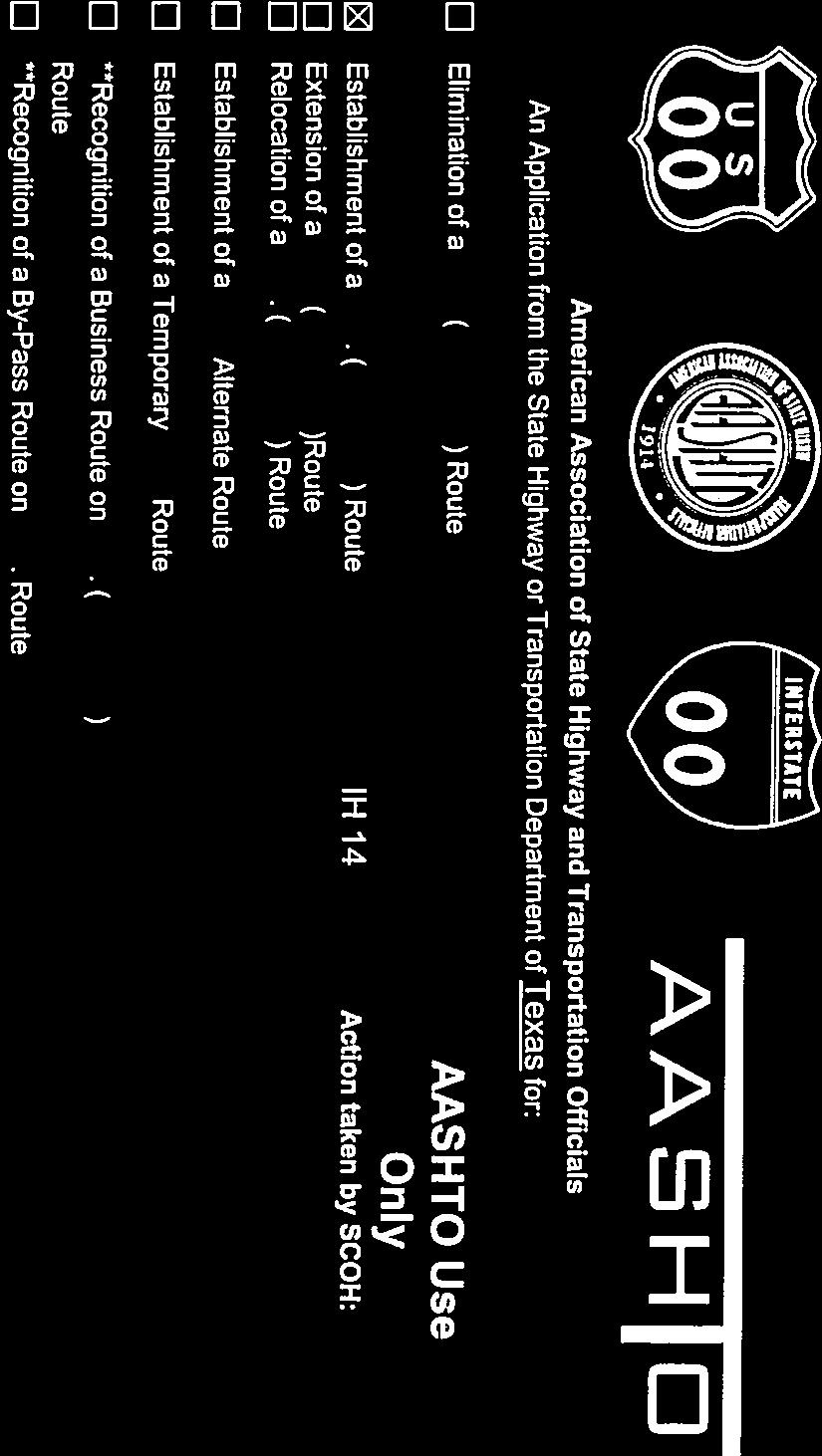
 Route IH 69 Action taken by SCOH: Extension of a U.S. (Interstate)Route") American Association of State Highway and Transportation Officials An Application from the State Highway or Transportation Department of Texas for: Elimination of a U.S. (Interstate) Route AASHTO Use Only
American Association of State Highway and Transportation Officials An Application from the State Highway or Transportation Department of Texas for: Elimination of a U.S. (Interstate) Route AASHTO Use Only
American Association of State Highway and Transportation Officials An Application from the State Highway or Transportation Department of
 American Association of State Highway and Transportation Officials An Application from the State Highway or Transportation Department of for: Elimination of a U.S. (Interstate) Route Establishment of a
Updated August 1, 2016
 Updated August 1, 2016 American Association of State Highway and Transportation Officials An Application from the State Highway or Transportation Department of North Carolina for: Elimination of a U.S.
Updated June 12, 2017
 Updated June 12, 2017 American Association of State Highway and Transportation Officials An Application from the State Highway or Transportation Department of for: Elimination of a U.S. (Interstate) Route
American Association of State Highway and Transportation Officials An Application from the State Highway or Transportation Department of
 American Association of State Highway and Transportation Officials An Application from the State Highway or Transportation Department of for: Elimination of a U.S. (Interstate) Route Establishment of a
Updated August 1, 2016
 5 Updated August 1, 2016 American Association of State Highway and Transportation Officials An Application from the State Highway or Transportation Department of Alabama for: Elimination of a U.S. (Interstate)
American Association of State Highway and Transportation Officials
 American Association of State Highway and Transportation Officials An Application from the State Highway or Transportation Department of FLORIDA for the Elimination of a U.S. (I) Route U.S. 98 Alternate
Application to AASHTO to recognize six suggested relocations of U.S. Bicycle Route 1 in the Northern Virginia District.
 September 7 th, 2007 Application to AASHTO to recognize six suggested relocations of U.S. Bicycle Route 1 in the Northern Virginia District. Acting District Administrator Mr. Morteza Salehi has endorsed
Geometric Design Tables
 Design Manual Chapter 5 - Roadway Design 5C - Geometric Design Criteria 5C-1 Geometric Design Tables A. General The following sections present two sets of design criteria tables - Preferred Roadway Elements
Roadway Design Manual
 Roadway Design Manual Manual Notice Archive by Texas Department of Transportation (512) 302-2453 all rights reserved Manual Notice 2009-1 From: Manual: Mark A. Marek, P.E Roadway Design Manual Effective
American Association of State Highway and Transportation Officials. Virginia. for
 American Association of State Highway and Transportation Officials An Application from the State Highway or Transportation Department of Elimination of a U.S. (Interstate) Route Establishment of a U.S.
FOR HISTORICAL REFERENCE ONLY
 To: From: Subject: Electronic Distribution Recipients MINNESOTA DEPARTMENT OF TRANSPORTATION Engineering Services Division Technical Memorandum No. 12-14-B-03 December 18, 2012 Jon M. Chiglo, P.E. Division
Design Criteria. Design Criteria
 F Design Criteria Design Criteria Ministry of Transportation Ministère des Transports DESIGN CRITERIA Page: 1 of 13 WORK PROJECT NO. N/A GO Bloomington Station TYPE OF PROJECT LOCATION Bloomington Road
WYDOT DESIGN GUIDES. Guide for. Non-NHS State Highways
 WYDOT DESIGN GUIDES Guide for Non-NHS State Highways 2014 GUIDE FOR Non-NATIONAL HIGHWAY SYSTEM (Non-NHS) STATE HIGHWAYS PRESERVATION REHABILITATION RECONSTRUCTION INTRODUCTION This Guide is directed to
WYDOT DESIGN GUIDES. Guide for. NHS Arterial (Non-Interstate)
") WYDOT DESIGN GUIDES Guide for NHS Arterial (Non-Interstate) 2014 GUIDE FOR NATIONAL HIGHWAY SYSTEM (NHS) HIGHWAYS (NHS ARTERIALS, Non-Interstate) PRESERVATION REHABILITATION RECONSTRUCTION INTRODUCTION
WYDOT DESIGN GUIDES Guide for NHS Arterial (Non-Interstate) 2014 GUIDE FOR NATIONAL HIGHWAY SYSTEM (NHS) HIGHWAYS (NHS ARTERIALS, Non-Interstate) PRESERVATION REHABILITATION RECONSTRUCTION INTRODUCTION
Roadway Design Manual
 Roadway Design Manual Revised December 2013 2013 by Texas Department of Transportation (512) 302-2453 all rights reserved Manual Notice 2013-1 From: Manual: Mark A. Marek, P.E Roadway Design Manual Effective
Gordon Proctor Director Policy on Accommodating Bicycle and Pedestrian Travel on ODOT Owned or Maintained Facilities
 Approved: Policy: 20-004(P) Responsible Office: Planning Gordon Proctor Director Policy on Accommodating Bicycle and Pedestrian Travel on ODOT Owned or Maintained Facilities I. POLICY STATEMENT: This policy
DESIGN MEMORANDUM WITH DESIGN EXCEPTIONS SP SP
 DRAFT NOT FINAL (Note: document was not finalized due to an eastbound stopping site distance design issue that requires more detailed bridge and roadway design considerations. This discussion starts on
City of Roseville Section 13 Design Standards. _Bikeways January 2016 SECTION 13 BIKEWAYS
 SECTION 13 BIKEWAYS 13-1 GENERAL The City of Roseville bikeway standards are designed to insure that transportation and recreational bikeways are constructed in a manner that would provide a safe and comfortable
3-13 UFC - GENERAL PROVISIONS AND GEOMETRIC DESIGN FOR ROADS, STREETS, WALKS, AND OPEN
 maintenance, and erosion. Stability is required to maintain the integrity of the pavement structure, and a slope stability analysis should be conducted for cuts and fills greater than 15 feet. For lower
CHAPTER 2G. PREFERENTIAL AND MANAGED LANE SIGNS
 2011 Edition - Revision 2 Page 275 Section 2G.01 Scope CHAPTER 2G. PREFERENTIAL AND MANAGED LANE SIGNS 01 Preferential lanes are lanes designated for special traffic uses such as high-occupancy vehicles
INDEX. Geometric Design Guide for Canadian Roads INDEX
 Acceleration lane, see Lanes, Acceleration Access, 8.1 Access Management and Functional Classification 8.2 Access Management by Design Classification 8.3 Access Configuration 8.4 Building Set-Back Guidelines
October 2004 REVISIONS (2) SUPERELEVATION DEVELOPMENT 11.3(2)
 SUPERELEVATION DEVELOPMENT 11.3(2)") October 2004 REVISIONS (2) Chapter 11 HORIZONTAL ALIGNMENT SUPERELEVATION DEVELOPMENT 11.3(2) Chapter 12 VERTICAL ALIGNMENT VERTICAL CURVES PASSING SIGHT DISTANCE 12.5(2) VERTICAL CURVES STOPPING SIGHT
October 2004 REVISIONS (2) Chapter 11 HORIZONTAL ALIGNMENT SUPERELEVATION DEVELOPMENT 11.3(2) Chapter 12 VERTICAL ALIGNMENT VERTICAL CURVES PASSING SIGHT DISTANCE 12.5(2) VERTICAL CURVES STOPPING SIGHT
THE FUTURE OF THE TxDOT ROADWAY DESIGN MANUAL
 THE FUTURE OF THE TXDOT ROADWAY DESIGN MANUAL Kenneth Mora, P.E. (Design Division) 10/10/2017 Table of contents 1 2 Reduction in FHWA design controlling criteria Innovative Intersection Guidance 3-7 8-42
MANUAL ON UNIFORM TRAFFIC CONTROL DEVICES INTRODUCTION
 2011 Edition Page I-1 MANUAL ON UNIFORM TRAFFIC CONTROL DEVICES INTRODUCTION 01 Traffic control devices shall be defined as all signs, signals, markings, and other devices used to regulate, warn, or guide
Paul Huston, P.E., Design-Build Coordinator Chuck Gonderinger, HDR Engineering. Minnesota Department of Transportation (the Department)
") To: From: Paul Huston, P.E., Design-Build Coordinator Chuck Gonderinger, HDR Engineering Date: March 20, 2001 Subject: Roadway Geometric Design Criteria Project: TH 14/218 Design-Build Project, SP 7408-29,
To: From: Paul Huston, P.E., Design-Build Coordinator Chuck Gonderinger, HDR Engineering Date: March 20, 2001 Subject: Roadway Geometric Design Criteria Project: TH 14/218 Design-Build Project, SP 7408-29,
Railroad Inspection Procedure Manual
 Railroad Inspection Procedure Manual Railroad Inspection Procedure Manual Table of Contents Introduction... 1 Inspection Report t For orm... 3 Instructions for Completing Inspection Report t For orms...
Attached for your reference please find project updates on ongoing VDOT construction projects in Southampton County.
 SOUTHAMPTON COUNTY BOARD OF SUPERVISORS Regular Session i July 25, 2016 6. HIGHWAY MATTERS A. PLAN PROJECT UPDATES Attached for your reference please find project updates on ongoing VDOT construction projects
Alberta Infrastructure HIGHWAY GEOMETRIC DESIGN GUIDE AUGUST 1999
 Alberta Infrastructure HIGHWAY GEOMETRIC DESIGN GUIDE AUGUST 1999,1'(; A ACCELERATION Data on acceleration from stop D-29 Effects of grade D-35 Intersections D-97, D-99 Lanes D-97, F-5, F-7, F-15, F-21,
November 2012: The following Traffic and Safety Notes were revised:
 CHANGE LIST for MDOT Traffic and Safety, TRAFFIC AND SAFETY NOTES Located at http://mdotcf.state.mi.us/public/tands/plans.cfm JANUARY 2014: The following Traffic and Safety Note was added: Note 705A Angled
RULES OF TENNESSEE DEPARTMENT OF TRANSPORTATION PUBLIC TRANSPORTATION, WATERWAYS AND RAIL DIVISION CHAPTER RAILROAD GRADE CROSSING STANDARDS
 RULES OF TENNESSEE DEPARTMENT OF TRANSPORTATION PUBLIC TRANSPORTATION, WATERWAYS AND RAIL DIVISION CHAPTER 1680-9-1 RAILROAD GRADE CROSSING STANDARDS TABLE OF CONTENTS 1680-9-1-.01 Purpose 1680-9-1-.05
Sponsored by the Office of Traffic and Safety of the Iowa Department of Transportation NOVEMBER 2001 CTRE
 PAVED SHOULDERS ON PRIMARY HIGHWAYS IN IOWA: AN ANALYSIS OF SHOULDER SURFACING CRITERIA, COSTS, AND BENEFITS EXECUTIVE SUMMARY Sponsored by the Office of Traffic and Safety of the Iowa Department of Transportation
Development of Guidelines for Bicycle Use of Controlled Access Facilities in Virginia
 Development of Guidelines for Bicycle Use of Controlled Access Facilities in Virginia VDOT Statewide Bicycle and Pedestrian Advisory Committee Fall Working Group Meeting October 30, 2013 Young-Jun Kweon,
A plan for improved motor vehicle access on Railroad Avenue in Provincetown
 A plan for improved motor vehicle access on Railroad Avenue in Provincetown February 2011 A plan for improved motor vehicle access on Railroad Avenue in Provincetown INTRODUCTION AND PROBLEM IDENTIFICATION
FY STATEWIDE TRANSPORTATION IMPROVEMENT PROGRAM New Jersey Department of Transportation Projects
 Barclay Street Viaduct NS9807 NS9807 This project will provide for the rehabilitation of the Barclay Street Viaduct, from Route 19 to Marshall Street, in order to increase the weight load of the structure.
ENGINEER S PRELIMINARY REPORT. for the #######-###### COLLISION
 ENGINEER S PRELIMINARY REPORT for the #######-###### COLLISION By: Lance E. Robson, P.E. October 3, 2005 1 INVESTIGATION OF THE #######-###### COLLISION ENGINEER S PRELIMINARY REPORT October 3, 2005 ---------------------------------------------------------------------------------------------------------------
FY 2004 TRANSPORTATION CAPITAL PROGRAM New Jersey Department of Transportation Projects
 Avenue P Bridge 03315 This project will address potential construction in the vicinity of the Avenue P Bridge. SPONSOR: City of Newark Bridge Preservation - Local Bridges NJTPA 288 DES STATE $400,000 CARGOMATE
Figure 3B-1. Examples of Two-Lane, Two-Way Marking Applications
 Figure 3B-1. Examples of Two-Lane, Two-Way Marking Applications A - Typical two-lane, two-way marking with passing permitted in both directions B - Typical two-lane, two-way marking with no-passing zones
Chapter Twenty-eight SIGHT DISTANCE BUREAU OF LOCAL ROADS AND STREETS MANUAL
 Chapter Twenty-eight SIGHT DISTANCE BUREAU OF LOCAL ROADS AND STREETS MANUAL Jan 2006 SIGHT DISTANCE 28(i) Chapter Twenty-eight SIGHT DISTANCE Table of Contents Section Page 28-1 STOPPING SIGHT DISTANCE
Long Island Rail Road Expansion Project Floral Park to Hicksville
 Long Island Rail Road Expansion Project Floral Park to Hicksville Final Environmental Impact Statement Appendix 1-D Complete Streets Policy Checklist April 2017 0902ML PIN: Project Location: 18A-4 Floral
Act 47 Exception Application Process (Permitting Bicycle Travel on Freeways)
") Act 47 Exception Application Process (Permitting Bicycle Travel on Freeways) Attached is a revised application process to permit Pedalcycle travel on the shoulders of freeways within the Commonwealth.
Act 47 Exception Application Process (Permitting Bicycle Travel on Freeways) Attached is a revised application process to permit Pedalcycle travel on the shoulders of freeways within the Commonwealth.
Engineering Report: Apache-Sitgreaves National Forests. Black Mesa Ranger District. Analysis of. National Forest System Roads (NFSRs) #s 504 & 169
 #s 504 & 169") Engineering Report: Apache-Sitgreaves National Forests Black Mesa Ranger District Analysis of National Forest System Roads (NFSRs) #s 504 & 169 for Motorized Mixed Use Designation Forest: Apache-Sitgreaves
Engineering Report: Apache-Sitgreaves National Forests Black Mesa Ranger District Analysis of National Forest System Roads (NFSRs) #s 504 & 169 for Motorized Mixed Use Designation Forest: Apache-Sitgreaves
City of Margate, Florida. Neighborhood Traffic Management Manual
 City of Margate, Florida Neighborhood Traffic Management Manual Table of Contents Page No. I. INTRODUCTION... 1 II. TRAFFIC CALMING REQUEST AND PROCESSING PROCEDURES... 2 1. COMPLETE AND SUBMIT PROJECT
ARTINSVILLE ENRY OUNTY REA RANSPORTATION TUDY
 ARTINSVILLE ENRY OUNTY REA RANSPORTATION TUDY DEVELOPED BY THE TRANSPORTATION AND MOBILITY PLANNING DIVISION OF THE VIRGINIA DEPARTMENT OF TRANSPORTATION IN COOPERATION WITH THE U.S. DEPARTMENT OF TRANSPORTATION,
TABLE OF CONTENTS. General... A. New Construction/Reconstruction (4R)...B. Resurfacing, Restoration and Rehabilitation (3R)...C
...B. Resurfacing, Restoration and Rehabilitation (3R)...C") - LOCAL AGENCY PROJECTS TABLE OF CONTENTS Section General... A New Construction/Reconstruction (4R)...B Resurfacing, Restoration and Rehabilitation (3R)...C Preventive Maintenance (PM)... D Design Exception...E
- LOCAL AGENCY PROJECTS TABLE OF CONTENTS Section General... A New Construction/Reconstruction (4R)...B Resurfacing, Restoration and Rehabilitation (3R)...C Preventive Maintenance (PM)... D Design Exception...E
CHAPTER 1 STANDARD PRACTICES
 CHAPTER 1 STANDARD PRACTICES OBJECTIVES 1) Functions and Limitations 2) Standardization of Application 3) Materials 4) Colors 5) Widths and Patterns of Longitudinal Pavement Marking Lines 6) General Principles
Who is Toole Design Group?
 2018 AASHTO Bike Guide Status Update NCHRP 15 60 Amalia Leighton Cody, PE, AICP & Kenneth Loen, PE Washington APWA October 4, 2018 Who is Toole Design Group? TDG is a full service engineering, planning
CTH M HIGHWAY PROJECT CTH Q to STH 113
 CTH M HIGHWAY PROJECT CTH Q to STH 113 PUBLIC INFORMATIONAL MEETING #3 Wednesday, May 25, 2005 Town of Westport Administration Building 5387 Mary Lake Road 6:00 p.m. to 8:00 p.m. PUBLIC INFORMATIONAL MEETING
Engineering Countermeasures for Transportation Safety. Adam Larsen Safety Engineer Federal Highway Administration
 Engineering Countermeasures for Transportation Safety Adam Larsen Safety Engineer Federal Highway Administration 360-619-7751 Adam.Larsen@DOT.GOV Countermeasure Selection Resources Manual for Selecting
What Engineering Can Do for You! Low Cost Countermeasures for Transportation Safety
 What Engineering Can Do for You! Low Cost Countermeasures for Transportation Safety Adam Larsen Safety Engineer Federal Highway Administration 360-619-7751 Adam.Larsen@DOT.GOV Adam Larsen TTP Safety Engineer
PERFORMANCE ACTIVITY 405 LIMB MANAGEMENT
 PERFORMANCE ACTIVITY 405 LIMB MANAGEMENT 405 LIMB MANAGEMENT ACTIVITY DESCRIPTION Cut and/or remove and/or grind tree limbs from the right-of-way. TRAFFIC CONTROL Utilize intermittent mobile operations
Traffic Control Inspection Checklist Segment:
 Traffic Control Inspection Checklist Segment: Simon Contractors Simon Contractors Originator: Description Reviewed by: Initials Date Distribution: Traffic Quality Manager, Site Assistant Traffic Manager
South Carolina Department of Transportation. Engineering Directive
 South Carolina Department of Transportation Engineering Directive Directive Number: ED-22 Effective: December 16, 2009 Subject: References: Purpose: This Directive Applies to: Considerations for Bicycle
TRAFFIC SIGNAL WARRANT STUDY
 TRAFFIC SIGNAL WARRANT STUDY 5 th STREET & ENCHANTED PINES DRIVE JANUARY 2013 TRAFFIC OPERATIONS ENGINEERING SERVICES/PUBLIC WORKS DEPARTMENT TABLE OF CONTENTS INTERSECTION LOCATION MAP ii INTRODUCTION
CITY OF WEST LAKE HILLS. Forest View Neighborhood Traffic Calming Study
 CITY OF WEST LAKE HILLS 901 South Mopac Expressway Building V, Suite 220 Austin, Texas 78746 Texas P.E. Firm Registration No. F-929 Klotz Associates Final Report Submittal: March 20, 2015 Revised Final
US Hwy. 64/264 Pedestrian Crossing at the Little Bridge Alternatives Analysis Public Meeting
 Town of Nags Head US Hwy. 64/264 Pedestrian Crossing at the Little Bridge Alternatives Analysis Public Meeting Prepared by: Department of Public Works August 8, 2013 Where traffic-control signals are not
Freeway System Considerations
 Session 11 Jack Broz, PE, HR Green May 5-7, 2010 Freeway System Considerations Mainline Transit: Shoulder Operations, BRT, Stations HOV, HOT, UPA Interchanges Exit Ramps Entrance Ramps Bridges Local Crossings
AASHTO is in receipt of the following member department interstate application.
 June 4, 2015 Mr. Greg adeau Deputy Administrator Federal ighway Administration 1200 ew Jersey Ave., S Washington, DC 20590 Dear Mr. adeau: AAST is in receipt of the following member department interstate
WEST AVENUE AND NEW ROAD TRAFFIC STUDY PART III WEST AVENUE CLOSURE ALTERNATIVES ANALYSIS
 WEST AVENUE AND NEW ROAD TRAFFIC STUDY PART III WEST AVENUE CLOSURE ALTERNATIVES ANALYSIS CITY OF LINWOOD ATLANTIC COUNTY, NEW JERSEY March 30, 2006 PREPARED FOR: City of Linwood 400 Poplar Avenue Linwood,
Traffic Impact Study. Roderick Place Columbia Pike Thompson s Station, TN. Transportation Group, LLC Traffic Engineering and Planning
 F i s c h b a c h Transportation Group, LLC Traffic Engineering and Planning Traffic Impact Study Roderick Place Columbia Pike Thompson s Station, TN Prepared March 2016 Ms. Gillian L. Fischbach, P.E.,
DISTRIBUTION: Electronic Recipients List TRANSMITTAL LETTER NO. (13-01) MINNESOTA DEPARTMENT OF TRANSPORTATION. MANUAL: Road Design English Manual
 MINNESOTA DEPARTMENT OF TRANSPORTATION. MANUAL: Road Design English Manual") DISTRIBUTION: Electronic Recipients List MINNESOTA DEPARTMENT OF TRANSPORTATION DEVELOPED BY: Design Standards Unit ISSUED BY: Office of Project Management and Technical Support TRANSMITTAL LETTER NO.
DISTRIBUTION: Electronic Recipients List MINNESOTA DEPARTMENT OF TRANSPORTATION DEVELOPED BY: Design Standards Unit ISSUED BY: Office of Project Management and Technical Support TRANSMITTAL LETTER NO.
Annual Progress Report from VDOT on the Effect of the Aging Population on State Agencies
 Annual Progress Report from VDOT on the Effect of the Aging Population on State Agencies HB 110 (2006 GA Session) Report to the Governor and General Assembly of Virginia Virginia Department of Transportation
Multimodal Design Guidance. October 23, 2018 ITE Fall Meeting
 Multimodal Design Guidance October 23, 2018 ITE Fall Meeting Introductions Jessica Wilson TDOT Multimodal Division Office of Multimodal Planning Program Supervisor Jessica.L.Wilson@tn.gov Ali Hangul TDOT
AGENDA ITEM 6 D THOMASVILLE ROAD (HERMITAGE BOULEVARD TO LIVE OAK PLANTATION ROAD) ROADWAY SAFETY AUDIT
 ROADWAY SAFETY AUDIT") May 15, 2018 AGENDA ITEM 6 D THOMASVILLE ROAD (HERMITAGE BOULEVARD TO LIVE OAK PLANTATION ROAD) ROADWAY SAFETY AUDIT TYPE OF ITEM: Discussion STATEMENT OF ISSUE The Florida Department of Transportation
May 15, 2018 AGENDA ITEM 6 D THOMASVILLE ROAD (HERMITAGE BOULEVARD TO LIVE OAK PLANTATION ROAD) ROADWAY SAFETY AUDIT TYPE OF ITEM: Discussion STATEMENT OF ISSUE The Florida Department of Transportation
PLACEMENT OF SIGNS RECOMMENDED PRACTICES SUB-SECTION
 Page 1 of 6 RECOMMENDED PRACTICES PART SECTION SUB-SECTION HIGHWAY SIGNS GENERAL General Proper positioning of signs is an important element in the overall control of traffic within a roadway network.
INTERSTATE 395 EXPRESS LANES NORTHERN EXTENSION ALTERNATIVES ANALYSIS TECHNICAL REPORT SEPTEMBER 2016
 INTERSTATE 395 EXPRESS LANES NORTHERN EXTENSION ALTERNATIVES ANALYSIS TECHNICAL REPORT SEPTEMBER 2016 INTERSTATE 395 EXPRESS LANES NORTHERN EXTENSION Alternatives Analysis Technical Report City of Alexandria,
City of Memphis. To: John E. Cameron, PE City Engineer. From: Kyle Wagenschutz. Cc: Manny Belen, Randall Tatum. Date: November 5, 2015
 City of Memphis Tennessee A C Wharton, Jr. Mayor Jack Sammons Chief Administrative Officer Division of Engineering John E. Cameron, P.E. City Engineer Memo To: John E. Cameron, PE City Engineer From: Kyle
FY 2005 TRANSPORTATION CAPITAL PROGRAM
 Avenue P Bridge 03315 This project will provide for the replacement of the existing two-track Conrail Railroad Bridge over Avenue P, a local urban street. The bridge and approaches will be built on the
Chapter 4 Traffic Analysis
 Chapter 4 Traffic Analysis PURPOSE The traffic analysis component of the K-68 Corridor Management Plan incorporates information on the existing transportation network, such as traffic volumes and intersection
section 4 Existing Conditions, Issues, and Options
 section 4 Existing Conditions, Issues, and Options 4.0 Existing Conditions, Issues, and Options This section analyzes each segment of the corridor on a street to street basis. Each segment is discussed
3.0 PROJECT DESCRIPTION
 The following section of the Draft EIR contains a description of the proposed Elk Grove Boulevard/SR 99 Interchange Modification project, consistent with the requirements of CEQA Guidelines Section 15124.
(This page left intentionally blank)
") (This page left intentionally blank) 2011 Edition - Revision 1 Page 553 Section 5A.01 Function CHAPTER 5A. GENERAL 01 A low-volume road shall be defined for this Part of the Manual as follows: A. A low-volume
(This page left intentionally blank) 2011 Edition - Revision 1 Page 553 Section 5A.01 Function CHAPTER 5A. GENERAL 01 A low-volume road shall be defined for this Part of the Manual as follows: A. A low-volume
Memorandum. Exhibit 60 SSDP To: Jenny Bailey, Senior Planner. From: Bill Schultheiss, P.E. (WA. P.E. #46108) Date: June 20, 2017
 Date: June 20, 2017") Memorandum To: Jenny Bailey, Senior Planner From: Bill Schultheiss, P.E. (WA. P.E. #46108) Date: June 20, 2017 Re: East Lake Sammamish Trail, Segment 2B Review King County has asked Toole Design Group
Memorandum To: Jenny Bailey, Senior Planner From: Bill Schultheiss, P.E. (WA. P.E. #46108) Date: June 20, 2017 Re: East Lake Sammamish Trail, Segment 2B Review King County has asked Toole Design Group
Off-road Trails. Guidance
 Off-road Trails Off-road trails are shared use paths located on an independent alignment that provide two-way travel for people walking, bicycling, and other non-motorized users. Trails specifically along
Roads that are intended to be included in the VDOT system of maintained roadways must meet the standards and specifications prescribed by the VDOT.
 SECTION 1 - GENERAL 1-1 Purpose This Manual has been prepared to promote uniform design procedures for designers and technicians in the development of property and roads in the County of Henrico, Virginia.
Residential Traffic Calming Program Guide. Town of Ashland, Virginia
 Residential Traffic Calming Program Guide Town of Ashland, Virginia August 1, 2006 TABLE OF CONTENTS A. INTRODUCTION... 1 B. GOALS... 1 C. CRITERIA... 1 D. IDENTIFYING NEIGHBORHOOD TRAFFIC CONCERNS...
INTERSTATE 540 IMPROVEMENT STUDY
 INTERSTATE 540 IMPROVEMENT STUDY WASHINGTON COUNTY AND BENTON COUNTY APRIL, 2006 INTERSTATE 540 IMPROVEMENT STUDY WASHINGTON COUNTY AND BENTON COUNTY April, 2006 Prepared by Parsons Transportation Group
SECTION 1A NEW JERSEY TURNPIKE GEOMETRIC DESIGN
 SECTION 1A NEW JERSEY TURNPIKE GEOMETRIC DESIGN Table of Contents Page No 1A.1 GENERAL...1 1A.1.1 DESIGN CONTROLS...1 1A.2 MAINLINE ROADWAYS...4 1A.2.1 ROADWAY DESIGNATION...4 1A.2.2 DESIGN SPEED...4 1A.2.3
Section 3A.04 Colors. Section 3B.10 Approach Markings for Obstructions
 Section 3A.04 Colors Markings shall be yellow, white, red, or blue, or purple. The colors for markings shall conform to the standard highway colors. Black in conjunction with one of the above colors shall
Secondary Road Program
 Secondary Road Program Joint Legislative Transportation Oversight Committee October 5, 2012 1 Secondary Roads Program The Big Picture The Secondary Road System Needs and Project Types Paved and Unpaved
Illini Union Champaign, IL. February 24, Paul Lorton, P.E. Safety Programs Unit Chief IDOT, Division of Highways, Bureau of Safety Engineering
 Illini Union Champaign, IL February 24, 2015 Paul Lorton, P.E. Safety Programs Unit Chief IDOT, Division of Highways, Bureau of Safety Engineering Temporary Concrete Barrier Pinning and Drop-off Policy
APPENDIX A: Complete Streets Checklist DRAFT NOVEMBER 2016
 APPENDIX A: Complete Streets Checklist DRAFT NOVEMBER 2016 Complete Streets Checklist MetroPlan Orlando s Complete Streets Checklist is an internal planning tool for staff to further implementation of
INDOT Complete Streets Guideline & Policy
 INDOT Complete Streets Guideline & Policy INTRODUCTION The Complete Streets guidelines build upon multiple efforts and promote a multimodal transportation system that is integrated and sustains land use
Traffic Impact Analysis Walton Acres at Riverwood Athletic Club Clayton, NC
 Traffic Impact Analysis Walton Acres at Riverwood Athletic Club Clayton, NC 1. TABLE OF CONTENTS INTRODUCTION...1 1.1. Site Location and Study Area...1 1.2. Proposed Land Use and Site Access...2 1.3.
CHAPTER 1 GENERAL DESIGN
 CHAPTER 1 GENERAL DESIGN 1.0 INTRODUCTION The purpose of this Manual is to provide its users with the current, uniform procedures and guidelines for the application and design of safe, convenient, efficient
TRANSPORTATION ALTERNATIVES PROGRAM: SELECTED PROJECTS AND FUNDING ALLOCATIONS
 ITEM #9: TRANSPORTATION ALTERNATIVES PROGRAM: SELECTED PROJECTS AND FUNDING ALLOCATIONS The Transportation Alternatives Program (TAP) created by MAP-21 requires that 50% of the program funds received by
GEOMETRIC DESIGN STANDARDS FOR NEW RESIDENTIAL SUBDIVISION STREETS TABLE 1A CG-6 CURB AND GUTTER SECTION
 TABLE 1A CG-6 CURB AND GUTTER SECTION HORIZONTAL AND VERTICAL CONTROLS CURB AND GUTTER ROADWAYS MAXIMUM 3:1 CUT OR FILL SLOPE CURVE DATA MIN. SIGHT DISTANCE PROJECTED TRAFFIC VOLUME (ADT) MIN. DESIGN SPEED
Introduction to Roadway Design
 Chapter Introduction to Roadway Design 1 This chapter lays the foundation for the Roadway Design course. You examine the roadway design workflow and the completed drawing files and review the project scope,
TABLE OF CONTENTS. Executive Summary
 Executive Summary Background... ES-1 Pedestrian Network... ES-2 Bikeway Network... ES-2 Collision History... ES-2 Public Input... ES-4 Conclusions and Recommendations... ES-4 1. Introduction and Setting
2.0 LANE WIDTHS GUIDELINE
 2.0 LANE WIDTHS GUIDELINE Road Engineering Design Guidelines Version 2.0.1 May 2018 City of Toronto, Transportation Services City of Toronto Page 0 Background In early 2014, Transportation Services initiated
Friday, May 20, :46 PM Cambria N Armstrong Fw: Wolf Creek REV.pdf
 David Johnson From: Sent: To: Cc: Subject: Attachments: Thomas Malecek Friday, May 20, 2011 12:46 PM david@westerneco.com Cambria N Armstrong Fw: Wolf Creek 05-16-11 REV.pdf David,
County of Fairfax, Virginia. Department of Transportation
 Fairfax County Parkway History 2 Planning began 50 years ago 1960s Washington s Regional Transportation Plan Recommends improved north/south travel Construct Capital Beltway and outer beltway Outer beltway
FY 2006 TRANSPORTATION CAPITAL PROGRAM
 Eden Lane Bridge over Whippany River NS9908 The existing structure was built in 1972 as a temporary single-span structure. The bridge consists of simply supported steel acrow panel trusses and is supported
Appendix C. Bicycle Route Signage
 Appendix C Bicycle Route Signage This page intentionally left blank. APPENDIX C - BICYCLE ROUTE AND WAYFINDING SIGNAGE Bicycle route signs are wayfinding signs that guide bicyclists along preferred, designated
PEDESTRIAN ACCOMMODATIONS DPS 201 AT INTERCHANGES
 PEDESTRIAN ACCOMMODATIONS DPS 201 AT INTERCHANGES UNDERSTANDING THE ISSUES Intersections of freeway ramp terminals at crossroads are the most critical components of an interchange Challenge: balance mobility
FY 2016 TRANSPORTATION ALTERNATIVES PROGRAM PROJECT SELECTION
 AGENDA ITEM #8: FY 2016 TRANSPORTATION ALTERNATIVES PROGRAM PROJECT SELECTION The Transportation Alternatives Program (TAP) created by MAP-21 requires that 50% of the program funds received by the state
SR 53 Corridor Study. Final Report Presentation. Friday, October 3, :00 AM to noon
 SR 53 Corridor Study Final Report Presentation Friday, October 3, 2014 10:00 AM to noon SR 53 Corridor Study Final Report Presentation Study Purpose: Investigate safety improvements along the SR 53 corridor
Figure 1: Graphical definitions of superelevation in terms for a two lane roadway.
 Iowa Department of Transportation Office of Design Superelevation 2A-2 Design Manual Chapter 2 Alignments Originally Issued: 12-31-97 Revised: 12-10-10 Superelevation is the banking of the roadway along
Truck Climbing Lane Traffic Justification Report
 ROUTE 7 (HARRY BYRD HIGHWAY) WESTBOUND FROM WEST MARKET STREET TO ROUTE 9 (CHARLES TOWN PIKE) Truck Climbing Lane Traffic Justification Report Project No. 6007-053-133, P 101 Ι UPC No. 58599 Prepared by:
The 2012 AASHTO Bike Guide: An Overview
 The 2012 AASHTO Bike Guide: An Overview Presentation by: Jennifer Toole, AICP, ASLA Peter Lagerwey August 10, 2012 {Enter Module Name on Master Slide} WEBINAR #1: OVERVIEW OF 2012 AASHTO BIKE GUIDE Today