University of Minnesota Nano Fabrication Center
|
|
|
- Phebe Williams
- 5 years ago
- Views:
Transcription
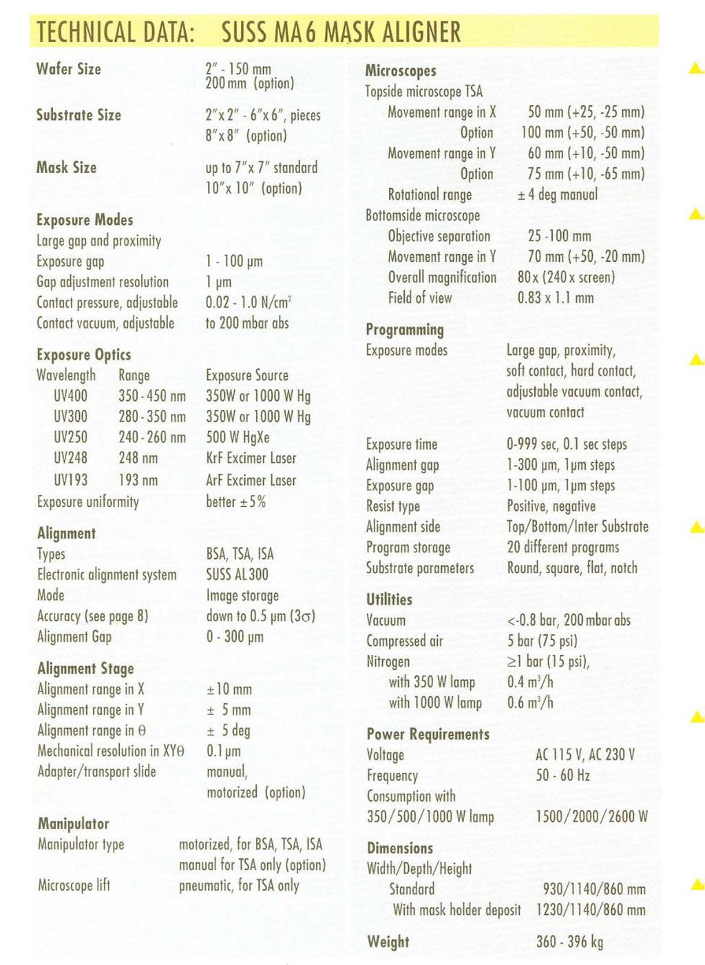
1 Equipment name: Karl Suss Mask Aligners Badger name: MA6 & Maba6 Revision number: 4 Models: Revisionist: Paul Kimani Location: Bay 2 Date: April 25, Introduction The Karl Suss MA6 and MABA6 are contact aligners used for optical lithography down to 1 micron. They can be used with 5 inch and 7 inch mask plates and are capable of processing pieces, 4 inch and 6 inch substrates. Each is equipped with a 350 watt, UV 400 mercury arc lamp (350nm 450nm wavelength range) capable of operating in constant power or constant intensity mode. NFC operates its aligners in constant intensity mode, where the power to the lamps automatically adjusts to maintain a constant intensity. Both are ideal for exposing broadband positive and negative resists. Both machines are used for front side alignment and additionally the MABA6 is used for front to back alignment, and for wafer to wafer alignment for wafer bonding. 2. Description a. A 350 watt mercury arc lamp with smart power supply capable of operating in constant power mode or constant intensity mode. The lamp is run in constant intensity mode, whereby as the lamp ages, power is adjusted automatically to keep the intensity constant. b. Front-side alignment is achieved using top-side microscope, mask and wafer placed on their respective seats. c. Back-side alignment through use of bottom viewing optics, CCD cameras with image grabbing ability and a TV monitor. Image grabbing allows registration of the bottom side features to a virtual image of the top side captured on the TV monitor. d. Six lithographic modes for exposure. They include: SOFT CONTACT, HARD CONTACT, LOW VACUUM CONTACT, VACUUM CONTACT, PROXIMITY and flood exposure programs. FLOOD EXPOSURE lithographic mode is not available on MABA6. e. 5-inch and 7-inch masks can be used in any of the aligners f. Three chuck sizes can be used with the aligners: piece chuck, 4-inch and 6-inch g. Alignment can be done using one or two objectives. Positional memory lock allows one to fast scan between two locations quickly. 3. Safety a. Do not look directly at the ultraviolet light or its reflection. The aligners lamps output 365nm, 405nm and 436 nm wavelengths light for a total of approximately 12mW/cm 2 intensity. b. Beware of moving parts on the aligner. The microscope assembly moves up and down. The exposure tool will move forward when exposing a wafer. Be careful to avoid putting any body part, clothing, or other material in the path of the moving parts. 1
2 4. Restrictions/Requirements a. Do not place heavy or sharp objects on the touch panel b. Do not lean on the anti-vibration table c. Do not turn any knobs more than a few degrees at a time. Turn all knobs with care. Handle all equipment gently and with care. d. Do not use acetone to clean the chuck. If needed, use a towel with some methanol or IPA. If you are having repetitive issues with wafer chuck vacuum, report the problem on coral and/or contact staff. e. Any chucks not in use should be placed in the chucks cabinet for safe keeping f. When handling the mask plate, take care not to damage the proximity flags g. Enable the aligner on CORAL before each use. 5. Required facilities a. Compressed air b. Vacuum c. Nitrogen gas d. Electrical power 6. Definitions a. Mask Holder - holds masks in place b. Chuck - holds wafer in place c. WEC Wedge Error Compensation. It occurs after loading the substrate. In this procedure, the wafer is leveled so that it is as close as possible to being parallel to the mask. There are two WEC options, contact and proximity. Contact WEC achieves parallelism by utilizing the flatness of the mask/wafer contact. Proximity WEC uses three proximity flags (see m) for parallelism adjustment. Of these two, the contact WEC has less error and is preferred unless circumstances dictate otherwise. If you need to use proximity WEC, consult staff prior to doing so. d. Direction arrow keys X- and Y- Move the microscope along the x- and y-axis. They are also used to change program parameters e. Fast key when activated (LED is on), they allow the microscope to move rapidly in either the x- or y-axis f. SEP keys These keys enable the alignment position of the chuck to be changed in finite steps of 1µm along the z-axis. The keys are active with the wafer loaded and in alignment position. When used, they increase or decrease the alignment gap between the mask and the wafer. g. ALIGN CONT/EXP Key Enables the operator to change the position of the exposure chuck between alignment gap and contact position with the mask (or proximity if the selected exposure program is proximity). This places the wafer in contact position (proximity) without exposure. Pressing the key again returns the wafer back to its original alignment position. h. ALIGNMENT CHECK key This triggers all parameters of an exposure program except the exposure. The key only works for Hard Contact, Vacuum contact and Low Vacuum Contact. Using this key allows one to check their final alignment before pressing the exposure key. 2
3 i. EXPOSURE Key After completing the alignment process, press this key to start exposure. j. TSA Key Top side alignment. The top microscope is used to align the mask to the top/front of the wafer. The topside of the substrate is then exposed. k. BSA Back Side Alignment (MABA6 only). The bottom side objectives are used to align mask features to the backside of the substrate. The topside of the substrate is then exposed. Although MA6 has keys and knobs for backside alignment, they are not functional and can be ignored. l. Multiple Exposure Key This key allows for the overall exposure to be broken down into equal shorter exposure intervals with defined wait times during which the substrate is not exposed. It may be useful in exposure of thick photoresists that have long exposure requirements. m. Proximity Flags The three pneumatically actuated flags located on the bottom side of the mask holder. They serve as spacers between the mask and substrate during proximity WEC. n. Overcurrent Error This error may occur when you press the exposure key. However, its cause emanates from bad WEC procedure that causes the motor which brings the mask and wafer into contact, to draw excessive current. The problem manifests itself when the exposure procedure is triggered. 7. Exposure Programs a. Soft Contact One of the six possible lithography modes. The substrate is brought into contact with the mask by a preset force exerted by the WEC head, during exposure. This mode is suitable for feature sizes 2 µm or larger. b. Hard Contact Similar to soft contact mode with an additional pillow pressure provided using nitrogen. This exerts an additional upward force on the wafer. This mode is suitable for feature sizes 1 µm or larger c. Vacuum Contact - The rubber seal on the chuck inflates to form a chamber, which is then evacuated. The parameters PreVac or Full Vac time in this mode allow the vacuum to proceed slowly. This aids in preventing alignment shift. The vacuum in the chamber cannot be adjusted (in contrast to Low Vacuum program). To diminish the vacuum, nitrogen is bled into the chamber after exposure. This mode is suitable for features sizes of 1 µm or less. d. Low Vacuum Contact Similar to vacuum mode except that the contact force can be reduced by bleeding a small amount of N 2 within the evacuated chamber. A knob allows one to make this vacuum adjustment. This mode is suitable for features sizes of 1 µm or less. e. Proximity - The mask and wafer are separated by an exposure distance specified by the user. There is no contact between the mask and the wafer. Before using this program, contact a staff member to verify that the flags are functioning correctly. We do not recommend use of this mode unless you situation dictates otherwise. f. Flood Exposure Used when no mask is required. A blank/clear glass mask is placed in the mask holder. Exposure proceeds as in other program modes above. This mode is only available on MA6. 3
4 8. Mask loading: a. Enable MA6 or MABA6 on CORAL b. If the mask holder is already out and placed on the shelf on the left, proceed to e) c. If a different mask holder is needed, disconnect the vacuum hose at the machine. Push in on the knurled knob and gently pull on the hose. Store the removed mask holder in the Karl Suss parts cabinet. Connect the vacuum hose for your new mask holder. d. If the mask holder is in the inserted position, gently pull it out taking care not to hold the proximity flags. Flip the mask holder and place it on the loading tray to the left of the machine. e. Place the mask in the mask holder (chrome side up) and align mask position against the fixed plate and positioning pins. Press the flashing ENTER key to turn the vacuum on. Gently press the silver tab to engage the spring locking mechanism. This serves as an additional protection should the vacuum grip fail. f. Turn the mask holder upright (the mask will now have the chrome side facing down), insert it onto the alignment stage guide and push it in all the way. Gently wiggle the mask left and right to ensure that the mask holder sits correctly on the alignment stage. Clamp the mask holder in the alignment stage by pressing the CHANGE MASK key. A Ready for Load message will appear on the LCD display. 9. Substrate Loading Three wafer chucks can be used; one for pieces that are at least 1 cm 2 area, one for 4-inch and one for 6-inch size substrates. Use the 4-inch wafer chuck with a 5-inch mask holder and a 6-inch chuck with a 7-inch mask holder. The vacuum grooves on the chuck need to be fully covered by the substrate. Care has to be taken when handling the chucks as replacements are pricey and not easily obtained. Any chuck not in use should be stored in the Karl Suss parts cabinet. a. Set the X- and Y-stage micrometers to 10 and the stage rotation knob to 0 to ensure that the resulting image is centered on the wafer. b. Confirm that you have the right-sized chuck for your alignment/exposure needs. If you need a different chuck, carefully lift off the chuck from the slide and place it in the Karl Suss parts cabinet. Place you desired chuck on the slide opening aligning the white mark on the chuck with the projecting pin on the slide. c. Press the LOAD key. Pull the slide all the way out. Place the wafer on the chuck with the flat facing the user and ensure that the wafer aligns against the three steel alignment pins. Press enter to turn the vacuum on the wafer on. d. Push the slide all the way into the machine. Press ENTER. WEC is performed and then the substrate is ready for alignment. 10. Selecting and editing a program a. Press SELECT PROGRAM key to choose an exposure program. Doing so will select one of the five lithography modes defined in 6 above. On MABA6, press SELECT PROGRAM key until appropriate program appears on the display. On the MA6, use the y-key pad to scroll through the six-program choices and then press SELECT PROGRAM again to load your choice. 4

5 b. For both tools, EDIT PARAMETERS key allows one to change the existing program s option. Press EDIT PARAMETERS key. EXP TIME will be displayed. Press Y-up/down key to increase/decrease the exposure time. Press X-key until AL GAP is displayed. Press Y-up/down key to set the AL GAP value. Press EDIT PARAMETERS key again to save the recipe. Coarse focus Adjustment for microscope s theta Objective separation knobs Mask Holder Illumination control knobs Y micrometer X micrometer θ micrometer Wafer chuck 5


6 University of Minnesota Nano Fabrication Center BSA magnification Fine focus for mask Fine focus for substrate Illumination control knobs 6
.")
7 Scan Key Microscope controls BSA controls not used on MA6 Set reference key Focus control for mask (top) or wafer (bottom) 11. TSA Setup a. The top objectives can be moved over the mask using the X-and Y- arrow keys. If the FAST key Led is lit green, the objectives move much more rapidly than when the FAST Key Led is toggled off. b. One can view the left side and the right side images simultaneously, if Split View mode is toggled (center). Alternatively, one can view a full image provided by the Left or Right side objective, if left or right side mode are toggled. c. The intensity of illumination may be adjusted using the illumination control knobs (see diagram) d. The Coarse focus is used to bring the objective s depth of focus into the fine focus range. Fine focus is adjusted using the fine focus knobs. The Top Substrate focus knobs are used to focus on the mask. The Bottom Substrate focus knobs are used to focus on the wafer. Focus control key allows one to switch between focusing on the mask and focusing on the wafer. When Top Substrate Key Led is lit green, one can manipulate the Top Substrate focus knobs. When the Led is off, one can manipulate the Bottom Substrate knobs. e. You can use the SET REFERENCE key to remember the microscope s position. Position the microscope to your first reference position. Press the SET REFERENCE key to activate it. Move the microscope to the second position. Press SCAN Key. The microscope moves to the first reference point. Pressing the SCAN key again moves the microscope to the second reference position. This allows one to easily locate dual positions for quick alignment. f. Verify that the BSA Microscope key is OFF if you are using the MABA6 aligner. g. The objectives separation knobs (see diagram) are used to adjust the distance between the objectives. To prepare for alignment, use X- and Y- keys and move objectives over the 7
8 mask and locate mask alignment marks. To move rapidly, toggle the FAST key, so that the Led is lit green. Use an objective separation knob to find the other alignment mark (if using split field). Use the adjustment for microscope s theta to keep the images on both sides parallel to each other. The adjustment for microscope theta allows the rotational angle of both objectives to be adjusted relative to each other. Use the illumination control knobs to control the amount of light going through each objective. Adjust TSA illumination if needed. Mask Alignment Marks Left Objective Right Objective h. Use (rarely) the large coarse focus knob to bring the objective s depth focus into the fine focus range. Fine tune the focus on the mask using the two focus knobs under the TOP SUBSTRATE. Focus control using TOP SUBSTRATE left and right knob is available when the Top/Bottom key is lit green. If it is not, toggle it so that it is illuminated green. 12. Wafer Alignment a. Alignment Marks: Below is the suggested alignment mark placement when designing a mask. It will allow the user to use both the MA6 and the MA6/BA6 contact aligners. Refer to the Mask Design SOP for further questions on how to design a mask. 8
9 Alignment Mark Placement for the MA6 and MA6/BA6 Contact Aligners Center of 100 mm Wafer Alignment Marks should go here. Wafer Chuck 25 mm 25 mm 45 mm 45 mm b. Ensure that the machine is in alignment mode. The ALIGN/CONT key is illuminated when the machine is in alignment mode. Use the X-, Y- and θ micrometers to manipulate the wafer relative to the mask. The two SEP keys can be used to increase/decrease the alignment gap if wafer is too close to or too far from the mask. c. Align the wafer to the mask using the X-, Y- and θ micrometers. Adjust wafer focus by toggling the TOP/BOTTOM key off. The focus is now on the bottom substrate and the focus control is on the BOTTOM SUBSTRATE knobs. Locate Wafer Alignment Marks Left Objective Right Objective 9
10 Align Wafer to Mask Alignment Marks Left Objective Right Objective d. Check alignment using either the ALIGN/CONT key or the Alignment check key. ALIGN/CONT key brings the wafer and the mask into contact without exposure and the ALIGNMENT CHECK key will activate all the steps in the contact program except the exposure. Check for any shift or misalignment. If further adjustment is required, toggle the ALIGN/CONT key or the ALIGNMENT CHECK key to separate the wafer and mask. If no change is needed, exposure can take place. ALIGNMENT CHECK is not available in Soft Contact or Proximity modes. 13. Wafer Exposure a. Press EXPOSURE key. The top side microscope assembly lifts and the exposure lamp housing slides forward over the mask. Exposure takes place for the selected amount of time, then the exposure lamp housing retreats to the back of the machine and the microscope assembly drops back. b. The exposed wafer can now be removed. Pull the slide out all the way, press ENTER to turn the wafer vacuum off, then remove the wafer and slide the wafer holder back into the machine. c. For resists that need long exposure, you can break down the exposure duration into short exposure periods with cooling periods, using MULTIPLE EXPOSURE key. To use this option, press MULTIPLE EXPOSURE key on the console. Use EDIT PARAMETERS to enter the exposure time, the duration when there is no exposure and the number of exposure cycles needed. If you need to expose for a total of 60 seconds in three cycles, then set your exposure time as 20 seconds and the number of cycles at 3 cycles. 14. Bottom side wafer alignment: This feature is available only with the MABA6. For this feature, use is made of bottom viewing optics, CCD cameras with image grabbing ability and a TV monitor. Image grabbing allows registration of the bottom side features to a virtual image of the top side captured on the TV monitor. An image of the mask is stored prior to loading the substrate. The mask and microscope are then locked into place while the substrate is loaded with patterned side down, resist side up. The patterned wafer is viewed by the bottom microscope, and alignment is accomplished by moving the wafer. Both the mask s stored image and the real time wafer image are viewed on the TV monitor during this procedure. 10
11 15. BSA Operating Instructions a. Have the mask loaded onto the mask holder as provided in instruction in section 8 above. Press BSA MICROSCOPE key to activate the bottom microscope. The X-Y and Fast keys can now be used to move the bottom microscope objectives. The TOP/BOTTOM light illuminates to indicate that the backside cameras are focused on the top substrate (the mask). Adjust backside illumination using the BSA knobs for left/right cameras as necessary. Toggle the magnification switch to low to begin with. b. Locate the mask alignment marks using the X and Y keys on the touch pad (use split field mode). Three keypads, Left, Both, and Right determine the bottom objectives mode of movement. When the Left key is selected, the left objective movement is independently controlled by the X-Y keys. The Right key controls the right objective movement only. The Both key controls movement of both objectives at the same time. c. Adjust the TOP SUBSTRATE left and right focus knobs to obtain a sharp image of the mask features. Turn knobs slightly (no more than a quarter turn at a time) then allow the image to come into focus. Continue with adjustments until alignment marks are focus. Toggle the magnification switch to HIGH, identify appropriate alignment marks and adjust focus as needed. d. The next step (that occurs prior to grabbing the mask image) is uncharacteristic. Unclamp the mask holder (by pressing CHANGE MASK) then clamp the mask holder again. Tap the mask holder frame gently and watch the screen image to see if there is any shift of the live image on the screen. The reason for doing is because the grip on the mask holder is not firm at all times and results in the mask holder creeping slowly to the left and away from user. When this shift happens after the GRAB IMAGE step we see an undesired alignment error. Only move to the next step after you see that there is no more movement when you tap the mask holder. e. Press the GRAB IMAGE key to capture and store a mask image. The screen will indicate IMAGE STORED when done. The cameras then automatically focus on the wafer plane. The TOP/BOTTOM key is no longer illuminated. If you need to cancel the stored image, press GRAB IMAGE again f. Press the LOAD key, and load the wafer with the pattern side facing down and the side coated with photoresist facing up. Press ENTER key to toggle the vacuum to the wafer on. Slide the tray into the machine and press the ENTER key. WEC will be performed and an image will appear on the screen. g. Locate the alignment marks on the wafer using the X, Y and θ micrometer screws. Adjust focus by adjusting the BOTTOM SUBSTRATE focus knobs. Align wafer alignment marks with alignment marks stored from the GRAB IMAGE step. Once the alignment is complete, press ALIGN/CONT key to bring the wafer and mask into contact, and then ress the EXPOSURE key. Below is a page from the manual describing this procedure 11

12 16. Unloading a wafer after exposure a. After the wafer has been exposed, pull the wafer slide all the way out. Unload the wafer and press enter to confirm you action. Push the slide back into the machine. 17. Unloading a wafer before exposure a. To unload the wafer, before exposure, press the UNLOAD key. Pull the slide out and press enter to release wafer vacuum and unload the wafer. Push the slide back into the machine. 18. Mask Unloading a. Press CHANGE MASK key. b. Pull the mask holder out and place it upside down on the loading tray positioned at the left of the machine. Press ENTER to turn the vacuum off. Pull back on the spring loaded locking device to separate it from the mask and lift the mask out. Leave the mask holder on the loading tray. 19. Using the piece chuck a. If the piece chuck is needed, carefully remove the 4-inch chuck and place it in the Karl Suss parts cabinet located at the entrance to the bay. b. Remove the piece chuck (it is stored in the same cabinet), and place in the aligner hole were the other chuck was located. 12
13 c. Plastic or Teflon coated tweezers are required to use the piece chuck to minimize any damage to the glass. d. Align per normal procedures. The piece chuck can accommodate anywhere from a quarter of a 4-inch wafer to one square centimeter piece e. Return piece chuck to the cabinet. Return 4-inch chuck to the aligner. 20. Problems/troubleshooting a. Mask features cannot be focused 1. The mask may be upside down. Reload mask correctly. The chrome (darker side) should be facing the wafer. 2. The mask may not be properly loaded onto the tray. Reload the Mask 3. The mask may not be resting flush against the tray. Possible particle or photoresist is on the mask. Clean the mask and reload b. Wafer is out of focus 1. The alignment gap may be too large. Adjust with the SEP keys or unload and set the alignment gap to a lower value 2. The WEC may have not taken place correctly. Unload the wafer and try again c. Wafer sticks to the mask either before or after exposure 1. If this occurs before exposure, increase the alignment gap. The mask should be cleaned before trying to expose another wafer. 2. If this occurs after exposure, either the mask may be dirty or the resist may not be baked enough. d. Loss of wafer vacuum 1. The wafer may still be held by vacuum. If so continue with the run. If there is no vacuum, try cleaning the backside of the wafer or the chuck with methanol or IPA on a wipe. 13
14 Appendix A. Tight tolerance adjustments on the MA6 and MABA6 contact aligners Before you start: 1) Verify that your mask is clean a) Photoresist on the mask will interfere with good contact between the mask and your wafer 2) Choose the right photoresist a) Use the thinnest photoresist possible. For example, do not use S1818 (coats approximately 1.8µ at 3,000 rpm for 30 seconds) to mask an etch of 500Å of silicon dioxide if S1805 (coats approximately 0.6µ at 3,000 rpm for 30 seconds) is sufficient. The thickness of your photoresist affects your ability to focus the aligner and achieve high resolution. It is practical to work initially with a practice wafer to determine how much resist thickness you actually need. 3) Alignment marks a) Have the right type of alignment marks or fiducials on your mask. If you need 1µm tolerance, have fiducials that show a 0.5µm shift. Aligning your wafer 1) Choose the right program a) For 1µm alignment, you will need to use the Low Vacuum or Vacuum programs. For 2µm alignment, hard contact may be sufficient. b) Use the right exposure and development time. If you do not use the right exposure and develop times, your features may be larger or smaller than the design calls for. If development is inappropriate then the features may not fully develop or they may be distorted or gone after development. Improper development or exposure time might have no effect on you current layer but future layers may be off the mark (say you seek to align a line on one layer to a space in the succeeding layer. If the line ends up being too wide, it may exceed the tolerance allowed by the space in the proceeding layer.) c) Use minimum alignment gap. You do not need a 30µm alignment gap when using S1805 on a flat wafer µm is a good place to start. If you wafer does not seem to be move when adjusting the micrometers, the alignment gap is too small. You want the smallest alignment gap possible while allowing your wafer to move freely while adjusting the micrometers. 2) Load your wafer a) Verify the chuck is clean. Put some methanol on a clean room towel and gently clean the chuck. b) Verify the chuck is level (it should sit correctly on the aligner and not be titled) c) When loading your wafer, check the pins/screws for flat alignment. Make sure they are lower than your wafer. If they are higher than your wafer, it will not be parallel to your mask. The alignment will be off. This can also trigger the OVERCURRENT error. 14
15 3) Align your wafer a) Use the highest objective possible when aligning your wafer. Do not use the 5x objective if you need an alignment tolerance of 1µm. Use at minimum the 10X objectives when aligning, after you have obtained your alignment marks using the 5X objectives. b) Starting at a µm alignment gap, focus on your mask alignment marks. Use the coarse focus knob, to get a clear image. With the top/bottom button lit, use the top substrate focus knobs to get the best possible image. c) Turn the top/bottom button off. Using the bottom substrate focus knobs, focus on your wafer alignment marks. d) Gradually lower the separation using the SEP keys. You should be able to get to an 8-10 µm gap and align your wafer. If your wafer does not move when adjusting the micrometer your alignment gap is too close. You may want to test this on a practice wafer first. e) Once your wafer is aligned with at least 10X objective, check the alignment. You can do this by slowly adjusting the separation to zero. Do not move the micrometers while doing this; doing so will cause your wafer to adhere to the mask. If your alignment marks are still aligned while in contact, increase the gap to 8-10 µm. Press Alignment Check key to verify alignment again. Press Expose. You can also go from zero contact directly to expose. The alignment check button runs the program first (like vacuum contact) which may give a slight focus improvement. Achieving tight alignments on the contact aligners takes practice. It may be best to try this on a practice wafer first before running your actual device. If you have trouble with focusing the aligners on fine features, do not proceed with the alignment. Contact a staff member for assistance and place a problem report in CORAL. If no staff member is available you can try the other contact aligner. B. System Specifications MA6 and MABA6 Contact Aligner Specifications Exposure optics: UV400 Lamp 350 watts Spectral lines (nm) 436 g-line 405 h-line 365 i-line Intensity mwatt 2 cm The aligners are set a constant intensity Mask sizes: 5 inch and 7 inch plates Wafer sizes: 2 Pieces > 1cm, 4 inch and 7 inch. Chucks available in the Karl Suss parts cabinet. 15
16 16
University of Minnesota Nano Fabrication Center
 Equipment name: Karl Suss Mask Aligners Badger name: MA6-P Revision number: 0 Model: MA6 Revisionist: Paul Kimani Location: Bay 4 PAN Date: September 17, 2015 1. Introduction The Karl Suss MA6-PAN is a
Equipment Standard Operating Procedure Greg Allion and Kimberly Appel
 Date Created: May 3, 2004 Date Modified: June 1, 2005 MA6/BA6 Mask Aligner Equipment Standard Operating Procedure Greg Allion and Kimberly Appel 1. Purpose 1.1. Photolithography involves transferring a
Karl Suss MA6 Mask Aligner SOP
 Page 1 of 11 Karl Suss MA6 Mask Aligner SOP Safety UV Exposure: The high energy light produced by the high pressure Mercury Xenon lamp can cause eye damage and skin burns. Be sure that the light guards
Warnings: Notes: Revised: October 5, 2015
 Karl Suss MA6 Mask Aligner Standard Operating Procedure Faculty Supervisor: Prof. Robert White, Mechanical Engineering (x72210) Safety Office: Peter Nowak x73246 (Just dial this directly on any campus
Standard Operating Manual
 Standard Operating Manual Karl Suss MA6 Mask Aligner Version 1.1 Page 1 of 24 Contents 1. Picture and Location 2. Process Capabilities 2.1 Cleanliness Standard 2.2 Substrate Size 2.3 Photo Mask Size 2.4
Usage Policies Notebook for Karl Suss MA6 Mid / Deep UV Mask Aligner
 Usage Policies Notebook for Karl Suss MA6 Mid / Deep UV Mask Aligner Revision date September 2014 2 Emergency Plan for Karl Suss MA6 Aligner Standard Operating Procedures for Emergencies Contact information
Karl Suss MJB4 Mask Aligner
 Karl Suss MJB4 Mask Aligner Tool Manager: Yong Sun ( yongs@princeton.edu; Office 8-8234; Cell 609-917-5076 ) Backup: George Watson ( gwatson@princeton.edu; Office 8-4626; Cell 732-996-2713 ) ******************************************************************************
KARL SUSS MJB3 MASK ALIGNER STANDARD OPERATING PROCEDURE
 KARL SUSS MJB3 MASK ALIGNER STANDARD OPERATING PROCEDURE Purpose of this Instrument: This instrument is for patterning photosensitive polymers with UV light. Location: White Hall 410 Cleanroom Primary
Warnings: Notes: Revised: January 8,
 OAI Model 204IR Mask Aligner Standard Operating Procedure Faculty Supervisor: Prof. Robert White, Mechanical Engineering (x72210) Safety Office: Peter Nowak x73246 (Just dial this directly on any campus
MJB4 Mask Aligner Operating Procedure. Effective Date: 07/12/2012 Author(s): Jiong Hua Phone:
: Jiong Hua Phone:") MJB4 Mask Aligner Operating Procedure Effective Date: 07/12/2012 Author(s): Jiong Hua Phone: 402-472-3773 Email: jhua2@unl.edu 1 1 Introduction 1.1 Key Words Karl Suss MJB4 Mask Aligner, Optical Lithography,
MJB4 Mask Aligner Operating Procedure Effective Date: 07/12/2012 Author(s): Jiong Hua Phone: 402-472-3773 Email: jhua2@unl.edu 1 1 Introduction 1.1 Key Words Karl Suss MJB4 Mask Aligner, Optical Lithography,
SOP for Karl Suss MJB3 #1 Mask Aligner
 SOP for Karl Suss MJB3 #1 Mask Aligner Rev. 5 (30/11/2016) Safety UV Exposure: The high-energy light produced by the high-pressure Mercury Xenon lamp can cause eye damage and skin burns. Be sure that the
KARL SUSS MJB3 UV400 Mask Aligner Standard Operating Procedure
 KARL SUSS MJB3 UV400 Mask Aligner Standard Operating Procedure Version: 1.0 February 2014 UNIVERSITY OF TEXAS AT ARLINGTON Nanotechnology Research Center (NRC) 1 TABLE OF CONTENTS 1 Introduction 3 1.1
COBILT CA-800 Mask Aligner Equipment Operation
 COBILT CA-800 Mask Aligner Equipment Operation For the Micro-Electronics Laboratory At University of Notre Dame Department of Electrical Engineering This user manual is not be removed from room 247A. This
Quintel Mask Aligner
 Quintel Mask Aligner (quintel) 1.0 1.0 Title Quintel Q4000 Mask Aligner 2.0 2.0 Purpose The Quintel Q4000 MA (Mask Aligner) is a top and bottom side contact lithography printer with the video-view split
Karl Suss Contact Aligner Operation
 Karl Suss Contact Aligner Operation Roger Robbins 6/31/2008 2 nd ed. 3/12/2009 The University of Texas at Dallas Erik Jonsson Engineering School of Engineering TITLE: Karl Suss Contact Aligner Operation
MJB-3 Mask Aligner Property of TAU MNCF August 2012
 MJB-3 Mask Aligner I. Power Up Sequence 1 LOG IN. Turn on Nitrogen & compressed air lines on the back wall. 2 Turn on the vacuum pump. 3 Flip the COMPRESSED AIR toggle on (up) Compressed air is used to
Approved by Principal Investigator Date: Approved by Super User: Date:
 Approved by Principal Investigator Date: Approved by Super User: Date: Standard Operating Procedure BNC OAI 200 Lithographic Mask Aligner (Aligner 3) Version 2011 June 2 I. Purpose This Standard Operating
Standard Operating Manual
 Standard Operating Manual AB-M Mask Aligner Version 1.1 Page 1 of 18 Contents 1. Picture and Location 2. Process Capabilities 2.1 Cleanliness Standard 2.2 Wafer Chuck Selection 2.3 Mask Holder Selection
Operation of the mask aligner MJB-55
 John Paul Adrian Glaubitz Operation of the mask aligner MJB-55 Department of Physics Faculty of Mathematics and Natural Sciences University of Oslo 1 Introduction The mask aligner is an essential tool
Approved by Principal Investigator Date: Approved by Super User: Date:
 Approved by Principal Investigator Date: Approved by Super User: Date: Standard Operating Procedure BNC OAI Lithographic Mask Aligner (Aligner 2) Version 2008 October 31 I. Purpose This Standard Operating
Photolithography. Operating Instructions
 Photolithography Operating Instructions The PR used during this laboratory session will be Microposit S1813 (from Shipley). Make sure everyone is following the laboratory protocol. Wear lab coats, safety
ABM MASK ALIGNERS. NanoFab 26 March 2009 A Micro Machining & Nanofabrication Facility
 ABM MASK ALIGNERS LOCATION: Optical Lithography PRIMARY TRAINER: Stephanie Bozic (2-6724, sbozic@ualberta.ca) SECONDARY TRAINER: Jolene Chorzempa (2-4823, jolenec@ualberta.ca) 1. OVERVIEW The ABM Mask
University of MN, Minnesota Nano Center Standard Operating Procedure
 Equipment Name: University of MN, Minnesota Nano Center Deep Trench Etcher Badger Name: deeptrench Revision Number: 9 Model: SLR -770 Sofware Version: CORTEX v4.5 Revisionists: Paul Kimani Location: Bay
University of MN, Minnesota Nano Center Standard Operating Procedure
 Equipment Name: Image Reversal Oven Badger name: ir-oven Revision #: 2 Model: YES 310 Revisionist: Paul Kimani Location: Bay 2 Date: October 29, 2013 1. Description The Yield Engineering Systems YES-310
OAI Model 200 Tabletop Mask Aligner Portland State University
 OAI Model 200 Tabletop Mask Aligner Portland State University WARNING: This machine exposes users to ultraviolet radiation. Do not touch the lens underneath the lamp hood as it may damage the machine and
NRF Suss Delta 80 Spinner SOP Revision /14/2016 Page 1 of 11. Suss Delta 80 Spinner SOP
 Page 1 of 11 Note: latest updates are blue. Table of Contents Suss Delta 80 Spinner SOP 1.0 Safety 2.0 Quality Controls and Calibration 3.0 Equipment Uses and Restrictions 4.0 Equipment Specifications
University of MN, Minnesota Nano Center Standard Operating Procedure
 Equipment name: STS Etcher Badger name: STS Revision number: 3 Model: 320 Revisionist: Paul Kimani Location: Bay 3 Date: 1 October 2013 A. Description The 320 is a manually loaded batch plasma etching
icreasepro Creaser Operators Manual
 6-2013 Version 3.0 icreasepro Creaser Operators Manual WWW.MBMCORP.COM 800-223-2508 TABLE OF CONTENTS SPECIFICATIONS.1a SAFETY PROCEDURES/CARE & MAINTENANCE..1b COMPONENT IDENTIFICATION 2 TOUCH SCREEN
OPERATION OF THE DIMPLER
 OPERATION OF THE DIMPLER After thinning your sample to ~80 μm you can now do a dimpling process to thin the center up to 10 μm. When you walk in and use the DIMPLER it should already be calibrated and
March CS-1701F Reactive Ion Etcher
 March CS-1701F Reactive Ion Etcher Standard Operating Procedure Faculty Supervisor: Prof. Robert White, Mechanical Engineering (x72210) Safety Office: Peter Nowak x73246 (Just dial this directly on any
Operation of the contact mask aligner Canon PPC 210 Projection Print Camera
 Operation of the contact mask aligner Canon PPC 210 Projection Print Camera Start-up Procedure: 1. Start the grey pump in the service corridor behind the aligner 2. Open the valve for the Nitrogen gas
Misaligned Folds Paper Feed Problems Double Feeds Won t Feed FLYER Won t Run iii
 Operator s Manual Table of Contents Operator Safety... 1 Introduction... 2 Unpacking and Setup... 3 Unpacking... 3 Setup... 4 FLYER Overview... 5 FLYER Diagram... 5 Capabilities... 5 Control Panel... 6
O P E R ATING INSTRUCTIONS FOR MODEL SPR-45 Automatic Screen and Stencil Printer
 O P E R ATING INSTRUCTIONS FOR MODEL SPR-45 Automatic Screen and Stencil Printer TABLE OF CONTENTS I. SPECIFICATIONS...3. II. SAFETY INSTRUCTIONS...4. III. INSTALLATION...5. IV. SET-UP...6. V. SYSTEM OPERATION...9.
Model 130M Pneumatic Controller
 Instruction MI 017-450 May 1978 Model 130M Pneumatic Controller Installation and Operation Manual Control Unit Controller Model 130M Controller is a pneumatic, shelf-mounted instrument with a separate
EE 432 Lab 3 PMOS source/drain lithography and diffusion
 EE 432 Lab 3 PMOS source/drain lithography and diffusion Group Leader: Yue Zhang Group Numbers: Yueyi Jiao, Yin Huang, Lafit Masud TA: Andy Hoyt Section: NO. 5 Introduction: In this lab, we will perform
R I T. Title: Amray 1830 SEM Semiconductor & Microsystems Fabrication Laboratory Revision: A Rev Date: 09/29/03 1 SCOPE 2 REFERENCE DOCUMENTS
 Fabrication Laboratory Revision: A Rev Date: 09/29/03 Approved by: Process Engineer / / / / Equipment Engineer 1 SCOPE The purpose of this document is to detail the use of the Amray 1830 SEM. All users
INSTRUCTION MANUAL. January 23, 2003, Revision 0
 INSTRUCTION MANUAL Model 810A In-Vitro Test Apparatus for 310B Muscle Lever January 23, 2003, Revision 0 Copyright 2003 Aurora Scientific Inc. Aurora Scientific Inc. 360 Industrial Parkway S., Unit 4 Aurora,
BASIC Z-STACK AND TIME SERIES SCAN ON THE ZEISS LIGHTSHEET Z. 1
 BASIC Z-STACK AND TIME SERIES SCAN ON THE ZEISS LIGHTSHEET Z. 1 The front door of the main body of the instrument may be open when you arrive. Take the sample chamber and slide it into position with the
Xactix XeF2 OPERATION MANUAL
 General Information The Xactix e-1 is a xenon difluoride (XeF 2) isotropic silicon etcher. XeF 2 is a vapor phase etch, which exhibits very high selectivity of silicon to photo-resist, silicon dioxide,
Standard Operating Procedure. For. PVD E-Beam
 P a g e 1 Standard Operating Procedure For PVD E-Beam P a g e 2 Introduction The PVD Electron-Beam Evaporator (E-Beam) thin film deposition machine uses a magnetically guided and collimated stream of electrons
Superconducting Susceptometer (MPMS-5S) Quantum Design Room 296 (MPMS)
 Quantum Design Room 296 (MPMS)") Superconducting Susceptometer (MPMS-5S) Quantum Design Room 296 (MPMS) Sensitivity: 1x10 11 A m 2 Applied DC fields: 0 T to 5 T Applied AC fields: 0 G to 3 G (zero-to-peak), 0.01 Hz to 1000 Hz Temperatures
Superconducting Susceptometer (MPMS-5S) Quantum Design Room 296 (MPMS) Sensitivity: 1x10 11 A m 2 Applied DC fields: 0 T to 5 T Applied AC fields: 0 G to 3 G (zero-to-peak), 0.01 Hz to 1000 Hz Temperatures
Issue: H Title: CHA E-Beam Evaporator Page 1 of 7. Table of Contents
 Title: CHA E-Beam Evaporator Page 1 of 7 Table of Contents Purpose/Scope... 2 2.0 Reference Documents... 2 3.0 Equipment/Supplies/Material... 2 4.0 Safety... 2 5.0 Set Up Procedures... 2 5.1 PC Logon and
Maintenance Manual. Note: This document is broken up into the following 6 sections of prescribed maintenance.
 How to Perform Maintenance On LPKF Circuit Board Plotters Requirements - LPKF Circuit Board Plotter - BoardMaster Software - 2.5 mm Allen wrench (for earlier model machines) - 3mm Allen Wrench - 4mm Allen
Powermax machine-side reference guide For mechanized applications with Powermax1000, Powermax1250 and Powermax1650
 Powermax machine-side reference guide For mechanized applications with Powermax1000, Powermax1250 and Powermax1650 This Powermax machine-side reference guide is a supplement to your Operator Manual and
[USING THE VITROBOT April 9, Using the Vitrobot
 Using the Vitrobot The Vitrobot Mk 3 (aka Mark III, Mark 3, etc.) can control both the local temperature and the local humidity during the process of plunge-freezing a grid for cryoem. It does require
Tire Inflation Cage Kit For servicing only single piece automotive, and most light truck tire/wheel assemblies
 Tire Inflation Cage Kit 85608214 For servicing only single piece automotive, and most light truck tire/wheel assemblies This is a supplement to your operating manual and covers the setup and use of the
Standard Operating Manual
 Standard Operating Manual Allwin21 AW610 RTP Page 1 of 18 Contents 1 Picture and Location 2 Process Capabilities 2.1 Cleanliness Standard 2.2 Recipes 2.3 Performance of Allwin21 AW610 RTP 3 Contact List
RIPPLE TANK - with rippler & kit
 GENERAL DESCRIPTION: RIPPLE TANK - with rippler & kit Cat: SW3430-001 with illuminator, rippler & kit. The ripple tank is used to investigate wave motion in a shallow trough of water to understand how
Nanofabrication Facility: PECVD SOP Rev. 00, April 24
 Author: Charlie Yao & Mario Beaudoin Email: charlieyao@gmail.com; Beaudoin@physics.ubc.ca Phone: 604-822-1853(MB). Purpose This document outlines the standard operation for the Trion Plasma Enhanced Chemical
QUORUM TECH 150RES THE FIRST AND THIRD WEEK WILL BE SET UP FOR CARBON COATING THE SECOND AND LAST WEEK WILL BE SET UP FOR GOLD COATING
 QUORUM TECH 150RES This document is intended to describe the function and use of the QuorumTech Q150RES system. Formal training and qualification by staff is required before gaining access to the tool.
University of Minnesota, MN Nano Center Standard Operating Procedure
 Equipment Name: HDPCVD Revision Number: 2 Badger Name: HDPCVD Revisionist: L. von Dissen Model: Advanced Vacuum Date: 10/25/2016 Apex SLR ICP Location: PAN, Bay 3 1 Description The Apex SLR ICP is a high
STS ICP-RIE. Scott Munro (2-4826,
 STS ICP-RIE LOCATION: Plasma Etch Area PRIMARY TRAINER: Scott Munro (2-4826, email@address.com) 1. OVERVIEW The STS ICP-RIE is available to users who require deep anisotropic silicon etching with near
Angstrom Dielectric Sputterer Operation Manual
 Angstrom Dielectric Sputterer Operation Manual I. System overview The Angstrom Dielectric Sputterer (ADS) has a similar interface as the Angstrom metal sputterer. It has two screens, the process screen
1.1 Equipment: substrate, wafer tweezers, metal targets 1.2 Personal Protective Equipment: nitrile gloves, safety glasses 1.
 Nanomaster NSC-3000 DC Magnetron Sputter Tool Standard Operating Procedure Faculty Supervisor: Prof. Robert White, Mechanical Engineering (x72210) Safety Office: Peter Nowak x73246 (Just dial this directly
Scanning Electron Microscope JEOL JSM F
 Scanning Electron Microscope JEOL JSM - 7600F How to Use This Manual You will be promised to obtain successful results if you follow this step by step manual gently and carefully. In order to that, you
Underwater Housing for Canon G7X Mark II
 Underwater Housing for Canon G7X Mark II Product Number 6146.08 Product Registration Please register your product at ikelite.com within 15 days of purchase. Our product registration database is the best
PETERSEN 161-SERIES HIGH PRESSURE LIFTING AIR BAGS OPERATING INSTRUCTIONS WARNING!
 PETERSEN 161-SERIES HIGH PRESSURE LIFTING AIR BAGS OPERATING INSTRUCTIONS WARNING! Read and understand instructions before using Petersen Plugs. Failure to comply may result in property damage, serious
Standard Operating Manual
 Standard Operating Manual Branson IPC 3000 O 2 Asher Copyright 2014 by Hong Kong University of Science & Technology. All rights reserved. Page 1 Contents 1. Picture and Location 2. Process Capabilities
User Manual GRI- 1500Li
 User Manual GRI- 1500Li Your Cart Tek caddy cart was thoroughly quality control checked and road tested before being shipped to your address. We do everything possible to assure that your caddy is in perfect
Underwater Housing for Panasonic Lumix DMC-ZS60, DMC-TZ80
 Underwater Housing for Panasonic Lumix DMC-ZS60, DMC-TZ80 Product Number 6170.60 Product Registration Please register your product at ikelite.com within 15 days of purchase. Our product registration database
632 AccuPro Set-up & Operation
 632 AccuPro Set-up & Operation Always check: Reel & Roller bearings Bent or broken blades Make sure the reel spins freely in the frame Place the Reel Into the Machine There are three lifting options for
STS PECVD Instructions
 STS PECVD Instructions I. Introduction A PECVD (Plasma Enhanced Chemical Vapor Deposition) reacts gases in a RF- (Radio Frequency) - induced plasma to deposit materials such as SiO 2 and Si X N Y. This
Login to ilab Kiosk. Revised 05/22/2018. Load your sample:
 Login to ilab Kiosk Load your sample: 1. Check: The analysis chamber pressure is
COMELEC C-30-S Parylene Coating System
 COMELEC C-30-S Parylene Coating System Comelec C-30-S Parylene deposition system Introduction Parylene is a polymere deposited at room temperature in a vacuum chamber (few µb). Parylene coating is perfectly
March Asher Operation
 March Asher Operation Roger Robbins 7/31/2006 The University of Texas at Dallas Erik Jonsson Engineering School of Engineering TITLE: March Asher Operation Page 1 of 13 March Asher Operation Roger Robbins
SEM LEO 1550 MANUAL. I. Introduction. Generality
 SEM LEO 1550 MANUAL RESERVATION POLICY: 2 booking slots maximum per day and per person (ie. 1h). 6 booking slots maximum per week and per person (ie. 3h). Reservation names must correspond to the operators.
Napa Technology Trouble Shooting. For Premier & Premier PLUS Models
 Napa Technology Trouble Shooting For Premier & Premier PLUS Models Before contacting Napa Technology for support, please check if the problem and solution are found below: Machine Is Off & All LCD s are
Standard Operating Manual
 Standard Operating Manual ARC12M Sputter Copyright 11.2015 by Hong Kong University of Science & Technology. All rights reserved. Page 1 Contents 1. Picture and Location 2. Process Capabilities 2.1 Cleanliness
Standard Operating Manual
 Standard Operating Manual Oxford Plasmalab 80 Plus Plasma Etcher Page 1 of 24 Contents 1. Picture and Location 2. Process Capabilities 2.1 Cleanliness Standard 2.2 Available Etching Materials 2.3 Performance
PUN M Manual Finger Punch Safety and Operation Manual
 PUN M Manual Finger Punch 300-600 - 900 Safety and Operation Manual For punching thermoplastic belting materials only. WARNING IMPROPER OR UNSAFE use of this tool can result in serious bodily injury! This
Plasma Asher: March PX-500 User guide (May-30, 2017)
") Plasma Asher: March PX-500 User guide (May-30, 2017) This is a highly versatile plasma etch tool that can etch using a direct plasma configuration (Oxygen plasma cleaner), a downstream plasma (Remote plasma),
Plasma Asher: March PX-500 User guide (May-30, 2017) This is a highly versatile plasma etch tool that can etch using a direct plasma configuration (Oxygen plasma cleaner), a downstream plasma (Remote plasma),
Version 1.0. icrease pro + Serial Number. Date
 icrease pro + 6-2016 Version 1.0 Serial Number Date This page is intentionally blank CONTENTS SPECIFICATIONS. 1a SAFETY PROCEDURES/CARE & MAINTENANCE..... 1b COMPONENT IDENTIFICATION.... 2 TOUCH SCREEN
ACV-10 Automatic Control Valve
 ACV-10 Automatic Control Valve Installation, Operation & Maintenance General: The Archer Instruments ACV-10 is a precision automatic feed rate control valve for use in vacuum systems feeding Chlorine,
MAINTENANCE PROCEDURE FOR X 650
 MAINTENANCE PROCEDURE FOR X 650 X 650 25. juli 2005-1/6 MAINTENANCE PROCEDURE FOR X 650 2 ND STAGE WARNING: This maintenance procedure is only for appointed Scubapro technicians that completed a course
Title: Xactix XeF2 Etcher Semiconductor & Microsystems Fabrication Laboratory Revision: A Rev Date: 03/23/2016
 Approved by: Process Engineer / / / / Equipment Engineer 1 SCOPE The purpose of this document is to detail the use of the Xactix XeF2 Etcher. All users are expected to have read and understood this document.
INSTALLATION INSTRUCTIONS PUSH BAR PULLMAN PANIC BOLT DEVICE TO EN 1125 : 2008
 INSTALLATION INSTRUCTIONS PUSH BAR PULLMAN PANIC BOLT DEVICE TO EN 1125 : 2008 0376/448/00 ISSUE 01 EMERGENCY PUSH PAD PULLMAN BOLT DEVICE TO EN 179 : 2008 1000mm MAXIMUM CLEAR OPENING HEIGHT WITH PUSH
JETFIRST 150 RTA SYSTEM OPERATING MANUAL Version: 2 Feb 2012
 JETFIRST 150 RTA SYSTEM OPERATING MANUAL Version: 2 Feb 2012 UNIVERSITY OF TEXAS AT ARLINGTON Nanofabrication Research and Teaching Facility TABLE OF CONTENTS 1. Introduction....2 1.1 Scope of Work.....2
Approved by Principal Investigator Date: Approved by Super User: Date:
 Approved by Principal Investigator Date: Approved by Super User: Date: Standard Operating Procedure BNC Commonwealth Dual Ion Beam Deposition System (CDIBS) Version 2010 February 14 I. Purpose This Standard
Prince Neos 1500 Review. Prince Neos A Review $
 A $1395.00 The is a lock-out machine and the natural extension of the venerable Neos 1000 Neos genre that has been around for some time. This machine, at this price, is an entry level machine that you
CZ52 Detail Strip, Disassembly, and Assembly Instructions Lonestar Fabrication & Design
 CZ52 Detail Strip, Disassembly, and Assembly Instructions 2008 Lonestar Fabrication & Design These instructions may be freely distributed and copied providing this page is included, and providing they
Exercise 2-3. Flow Rate and Velocity EXERCISE OBJECTIVE C C C
 Exercise 2-3 EXERCISE OBJECTIVE C C C To describe the operation of a flow control valve; To establish the relationship between flow rate and velocity; To operate meter-in, meter-out, and bypass flow control
NORDSON MARCH PX-1000 PLASMA ASHER STANDARD OPERATING PROCEDURE Version: 1.0 July 2016
 NORDSON MARCH PX-1000 PLASMA ASHER STANDARD OPERATING PROCEDURE Version: 1.0 July 2016 UNIVERSITY OF TEXAS AT ARLINGTON Nanotechnology Research Center TABLE OF CONTENTS 1. Introduction..3 1.1 Scope of
The SPI Sputter Coater Handbook
 The SPI Sputter Coater Handbook Coating of Specimens SPI-Module Sputter Coater with Etch Mode 1. Mount the specimens onto the SEM stub. Keep in mind that many adhesives have high vapor pressure solvents
DIRECT DRIVE DIXIE DOUBLE SEAMER Model 25D
 OPERATOR'S MANUAL DIRECT DRIVE DIXIE DOUBLE SEAMER Model 25D LUBRICATE DAILY: A. Gears inside gear housing at chuck shaft (1) Oil B. Seam rolls and cam rolls (4) - Oil C. Seam roll levers through gear
Glove Box Installation Manual
 Glove Box Installation Manual 1998 by M. Braun Company File: GB-UNI-INS.DOC! Edition 08-00 by M. Boutin! Subject to be changed without notice Glovebox Installation Your Glove box has been fully assembled,
GRAVITY PROBE-B GYRO HOUSING LITHOGRAPHY PROCESS
 PO105 July 15,1997 LITH71597.DOC R. Shile GRAVITY PROBE-B GYRO HOUSING LITHOGRAPHY PROCESS Document Revision Record Rev Date ECO No. Pages Affected Description 1. PHOTORESIST APPLICATION EQUIPMENT AND
OPERATOR S MANUAL Ar-Gone Weld Gas Analyzer
 July 2011 OPERATOR S MANUAL Ar-Gone Weld Gas Analyzer WARNING! Before operating this product, read and understand this Operator s Manual. Become familiar with the potential hazards of this unit. Contact
A4s Operation Manual
 A4s Operation Manual Safety Instruction Please read this manual carefully, also with related manual for the machinery before use the controller. For installing and operating the controller properly and
Mini Mr.Bulletfeeder by Double-Alpha
 Mini Mr.Bulletfeeder by Double-Alpha User Manual Thank you for choosing the Mini Mr.Bulletfeeder by Double-Alpha! This newly designed product will give you years of reliable service. It will make your
SPUTTER STATION STANDARD OPERATING PROCEDURE
 SPUTTER STATION STANDARD OPERATING PROCEDURE Purpose of this Instrument: This instrument is used for deposition of thin metal or oxide films. Source materials supplied by WVU Shared Research Facilities:
Plasma Cleaner. Yamato Scientific America. Contents. Innovating Science for Over 125 Years. Gas Plasma Dry Cleaner PDC200/210/510 PDC610G.
 Yamato Scientific America Innovating Science for Over 125 Years Plasma Cleaner Contents Gas Plasma Dry Cleaner PDC200/210/510 PDC610G Gas Plasma Reactor 145 146 147 149 144 Gas Plasma Dry Cleaner Plasma
5.1.3 Mechanical Hazards Drive assemblies have sufficient power to cause injury. Keep hands, fingers, clothing and tools clear of moving parts.
 Approved by: Process Engineer / / / / Equipment Engineer 1 SCOPE The purpose of this document is to detail the use of the PE4400. All users are expected to have read and understood this document. It is
MyControl Bathing System Signature Series
 MyControl Bathing System Signature Series Touch Assist Touch Pad and CM Technologies Seal Pressure Regulation Instructions Acceptable seal inflation pressure setting must be varified, and adjusted if necessary,
mechanical APPLICATION
 mechanical APPLICATION Many SWAROVSKI ELEMENTS, such as Rivets, Jeans Buttons, Snap Fasteners, Decorative Buttons and Magnet Fasteners, can be applied manually or mechanically, using either semi- or fully
Quadair. Air Hockey Table Owners Manual. Assembly operation and care instuctions. Serial # Distributed By. Sales Person. Technical Service #
 Version 12.1.11 Quadair Air Hockey Table Owners Manual Assembly operation and care instuctions. Serial # Distributed By Sales Person Technical Service # QUADAIR PATENTED WORLDWIDE Forward First, we would
Basic ICP Operating Procedures
 Center for High Technology Materials 2 February, 2009 University of New Mexico Created by Beth Fuchs Basic ICP Operating Procedures INTRODUCTION: The ICP is an inductively coupled plasma etching system,
Angstrom E-Beam Instructions. PROCESS CHECKS: the tooling factors of each metal; Ti/Au layer for wire bonding pull test.
 Angstrom E-Beam Instructions Tool Manager: Joe Palmer (jpalmer@princeton.edu) Office: 8-4706; Cell:609-751-1353 Backup: David Barth (dbarth@princeton.edu) Office: 8-4626; Cell: 610-405-8227 PROCESS CHECKS:
Instructions for Assembly, Installation, and Operation of the Gas Addition Kit Accessory with the CEM Discover Systems
 Corporation Issued: 5/09 P/N: 600104 Rev. 2 Instructions for Assembly, Installation, and Operation of the Gas Addition Kit Accessory with the CEM Discover Systems The Gas Addition Accessory permits the
RARS5000 AIR BODY SAW OWNER S OPERATING MANUAL
 RARS5000 AIR BODY SAW OWNER S OPERATING MANUAL DESCRIPTION 1. No mar 2. No mar tip 3. Housing grip 4. Trigger 5. Air inlet 6. Air inlet plug 7. Plastic board Important! It is essential that you read the
Mounting and Operating Instructions EB 8546 EN. Supply Pressure Regulator Type Fig. 1 Supply pressure regulators
 Supply Pressure Regulator Type 4708 Type 4708-5352 on Type 3730 Positioner Type 4708-52 with filter receptacle Type 4708-6252 on Type 3372 ctuator Fig. Supply pressure regulators Mounting and Operating