TABLE OF CONTENTS 1. INTRODUCTION 2. TRAFFIC ENGINEERING FUNDAMENTALS 9. SYSTEM CONTROL 3. DATA COLLECTION 4. SIGNAL PHASING 10. SPECIAL OPERATIONS
|
|
|
- Amelia Harrison
- 5 years ago
- Views:
Transcription
1
2
3 TABLE OF CONTENTS 1. INTRODUCTION 2. TRAFFIC ENGINEERING FUNDAMENTALS A. Volume, Demand, and Capacity 2-1 B. Performance Measures 2-7 C. Critical Lane Volume Analysis DATA COLLECTION 4. SIGNAL PHASING A. NEMA Phase Numbers 4-1 B. Left-Turn Phases 4-2 C. Phase Sequences 4-9 D. Right-Turn Phases 4-15 E. Pedestrian Phases ACTUATED CONTROL A. Basic Types of Signal Control 5-1 B. Primary Detection Functions 5-1 C. Types of Detectors 5-2 D. Basic Detector Settings BASIC TIMING PARAMETERS A. Minimum Green Interval 6-1 B. Pedestrian Walk Interval 6-3 C. Pedestrian Clearance Interval 6-3 D. Vehicle Extension 6-6 E. Yellow Change Interval 6-10 F. Red Clearance Interval 6-13 G. Maximum Green Interval VOLUME-DENSITY TIMING PARAMETERS A. Variable Initial 7-1 B. Gap Reduction TIME-OF-DAY TIMING PARAMETERS A. Common TOD Applications 8-1 B. Additional TOD Applications SYSTEM CONTROL A. Cycle Length 9-3 B. Split 9-4 C. Offset 9-17 D. Additional Coordination Tools 9-26 E. System Types 9-29 F. Advanced System Operations SPECIAL OPERATIONS A. Advance Warning Flasher 10-1 B. Coordinated-Actuated Systems 10-2 C. Split Demand 10-3 D. Preemption 10-4 E. Single-Point Urban Interchange 10-9 F. Maryland T Intersection STANDARDS, FORMS, AND PROCEDURES GLOSSARY A. Roles and Responsibilities 11-1 B. SHA Policy for Determining Yellow Timing at Intersections 11-8 C. SHA Part-Time Signal Operation Worksheet D. SHA Signal Timing Chart E. SHA Capacity Procedures for Intersections Critical Lane and Queuing Analysis F. Isolated Intersection Signal Timing Checklist REFERENCES
4
5
6 1. INTRODUCTION Purpose The following guidelines and recommendations have been written for the preparation of traffic signal timing documents for the Maryland State Highway Administration s (OOTS). The guidelines and recommendations pertain to signal timings for new or existing traffic signals on state roadways where signals are maintained by SHA. It is anticipated that the guidelines will also be useful for other traffic signals not noted above. Objectives of Traffic Signal Timing The overall objective of signal control is to provide for safe and efficient traffic flow at intersections, along arterials, and throughout roadway networks. Retiming signals is a cost-effective technique to improve traffic flow, reduce fuel consumption, eliminate unnecessary stops and delays, improve safety, and reduce impacts to the environment. Regular timing adjustments can delay the need for major roadway reconstruction. The functional objective of traffic signal timing is to alternate the right-of-way among various phases in such a way as to: o Provide for the orderly movement of traffic o Minimize delay to vehicles and pedestrians o Reduce the potential for safety conflicts o Maximize the capacity of each intersection approach The basic objectives are not always compatible. For example, delay may be minimized by using as few phases as possible and the shortest practical cycle length. However, reducing the potential for crashes requires fewer conflicting movements, which leads to multiple phases and longer cycle lengths. It is necessary to exercise engineering judgment to achieve a feasible balance of objectives. Page 1-1
7
8 2. TRAFFIC ENGINEERING FUNDAMENTALS A. Volume, Demand, and Capacity Volume, demand, and capacity all have the same unit of measure, vehicles per hour (vph); however, the applications and measurements are different. For example, if vehicles are counted at a defined location for one hour: o Volume is the number of vehicles counted passing the location in one hour o Demand is equal to the volume plus the number of vehicles that wanted to pass the location, during the one-hour time period but were prevented from doing so due to congestion o Capacity is the maximum volume that could be accommodated by the intersection at the defined location With respect to manual turning movement counts at signalized intersections: o During non-congested periods, turning movement counts (volumes) are approximately equal to the demand o During periods of heavy congestion (i.e., over-capacity conditions), turning movement volume counts (volumes) are approximately equal to the capacity for the respective movement. The demand can be determined by counting upstream on the approach where traffic is unaffected by the intersection. These counts should be performed where queues are not present using either automatic traffic recorders ( tube counts ) or system detectors located at an upstream intersection. Peak Hour Volume For signal timing applications, peak hour volumes are required for each turning movement. Peak hour volumes are determined by first identifying the peak hour for the intersection, which is the 60- minute time period with the highest total intersection volume for four consecutive 15-minute periods. The corresponding 60-minute volumes for each movement within the peak hour are the peak hour volumes. Page 2-1
9 Example 2.1: Turning movement counts were performed at a signalized intersection between 7:00 AM and 9:00 AM. The following is the total intersection volume (i.e., sum of all individual turning movement volumes) summarized into 15-minute intervals. Time period 7:00 7:15 AM 7:15 7:30 AM 7:30 7:45 AM 7:45 8:00 AM 8:00 8:15 AM 8:15 8:30 AM 8:30 8:45 AM 8:45 9:00 AM 15-minute volume Step 1: Calculate the volume for each 60-minute time period (i.e., four consecutive 15- minute periods). Time period 60-minute volume 7:00 8:00 AM 7:15 8:15 AM 7:30 8:30 AM 7:45 8:45 AM 8:00 9:00 AM = 1, = 1, = 1, = 1, = 1,305 The peak hour is 7:30 8:30 AM and the peak hour volume equals 1,354 vph. Step 2: Calculate the peak hour volume for each movement using the same four consecutive 15-minute periods as determined in Step 1. For example, the following count data was collected for the westbound through movement: Time period 7:00 7:15 AM 7:15 7:30 AM 7:30 7:45 AM 7:45 8:00 AM 8:00 8:15 AM 8:15 8:30 AM 8:30 8:45 AM 8:45 9:00 AM 15-minute volume westbound through The peak hour volume for the westbound through movement is 221 vph. Page 2-2
10 Peak Hour Factor (PHF) The peak hour factor (PHF) is the measure of variation, or fluctuation, in volume during the peak hour. The PHF is defined as follows: PHF = 4 peak hour volume ( peak15 - minute volume) The PHF can be calculated for each movement, approach, and/or for the total intersection. The PHF ranges between 0.25 and 1.0, and a lower PHF indicates a higher degree of variation in the peak hour volume. The PHF for the intersection in Example 2.1 is calculated as follows: PHF = 1,354 = Similarly, the PHF for the westbound through movement in Example 2.1 is calculated as follows: PHF = 221 = Although signal timings are typically based on hourly volumes, the PHF can be used to adjust the peak hour volume to account for significant fluctuations in demand (e.g., at intersections that serve schools or businesses with shift work). The adjusted volume is typically referred to as the maximum flow rate, which can be used to increase the amount of green time for the specific movement or approach that experiences the fluctuations. peak hour volume maximum flow rate = PHF Saturation Flow Rate The saturation flow rate is the theoretical maximum number of vehicles that can cross the stop line in one approach lane if the approach signal was continuously green. The saturation flow rate depends on roadway geometrics, driver characteristics, and traffic conditions, which can vary substantially for different lanes and approaches at a signalized intersection. For signal timing purposes, lanes or approaches with low saturation flow rates require more green time each cycle to serve the same number of vehicles as lanes or approaches with high saturation flow rates. The saturation flow rate can be computed using the formula and adjustment factors presented in the Highway Capacity Manual (HCM) or measured in the field. The computational HCM method uses a base saturation flow rate of 1,900 vehicles per hour per lane (vphpl), and then the value is adjusted for grade, lane width, intersection location, and adjacent parking. The process for measuring the saturation flow rate in the field is provided on the following worksheet. Page 2-3
11 Saturation Flow Study Field Worksheet Location: Direction: Lane: Date: Time: Observers: Comments: Instructions 1. At the beginning of the green interval, identify the fourth and last vehicles in the queue. The queue must be at least seven vehicles long. 2. If the queue is more than ten vehicles long, identify the tenth vehicle in the queue. 3. Start the stopwatch when the rear axle of the fourth vehicle in the queue crosses the stop line. 4. Stop the stopwatch when the rear axle of the last vehicle in the queue (i.e., the seventh, eighth, ninth, or tenth vehicle) crosses the stop line. For example, if there were nine vehicles in the queue at the start of green, then only the time between the fourth and ninth vehicle should be recorded that cycle. 5. Repeat steps 1 4 for the next cycle. CYCLE Column Sums: TIME (SECONDS) BETWEEN 4 TH VEHICLE IN QUEUE AND 7 TH VEHICLE 8 TH VEHICLE 9 TH VEHICLE 10 TH VEHICLE (a) (b) (c) (d) 3600 total number of cycles observed Measured SaturationFlow Rate (vph) = (a) (b) (c) (d) Page 2-4
12 Capacity The capacity of a lane at a signalized intersection is determined by factoring the saturation flow rate by the percentage of green time allocated to serve the lane. The capacity is computed by: g c = s C where, c = capacity of lane, vphpl s = saturation flow rate, vphpl g = green time for the phase serving the lane, sec C = cycle length, sec Example 2.2: The following data was collected at a signalized intersection: o Cycle length, C = 60 sec o East/West through phase green time, g = 20 sec o North/South through phase green time, g = 30 sec o Yellow plus all-red time (each phase), Y+AR = 5 sec o Saturation flow rate (all approaches), s = 1,900 vphpl Step 1: Calculate the capacity for the east/west through phase. 20 sec c = 1,900 vphpl = 633 vphpl 60 sec Step 2: Calculate the capacity for the north/south through phase. 30 sec c = 1,900 vphpl = 950 vphpl 60 sec Step 3: Calculate the capacity for the entire intersection. 50 sec c = 1,900 vphpl = 1,583 vphpl 60 sec It is important to understand the relationship between cycle length and capacity. For example, if the cycle length is increased and the number of phases remains the same, the percentage of green time per hour is increased (assuming the yellow plus all-red intervals remain constant) which increases capacity. However, it is important to point out that maximizing capacity is not always the primary goal of signal timing. Effective signal timing balances capacity, safety, queue lengths, and delay. Page 2-5
13 V/C Ratio The V/C ratio measures how the demand at an intersection is served by the capacity. The V/C ratio is typically calculated as follows: V C = Peak Hour Volume Capacity = ( Peak Hour Volume) C s g where, s = saturation flow rate, vphpl g = green time for the phase serving the lane, sec C = cycle length, sec Although the V/C ratio can be calculated for a single lane, lane groups, approaches, or the entire intersection, the most common application is to calculate the V/C ratio for each critical movement (see Critical Lane Volume Analysis). It is desirable that all phases be timed to provide sufficient capacity to handle the demand (i.e., the V/C ratio for each phase should be less than 1.0). A common technique is to distribute the green time so that all phases have the same V/C ratio. Over-Capacity Conditions Intersections that are over capacity (i.e., have a V/C ratio greater than 1.0) are often characterized by excessive delays and long queues that carry over from cycle to cycle or extend into upstream intersections. When queues spill back into an upstream intersection, the capacity of the upstream intersection is reduced because vehicles are restricted from entering or clearing the intersection at the saturation flow rate. Similarly, long queues at isolated intersections often block storage lanes or extend into adjacent travel lanes, which reduces the capacity of the blocked movement(s). The following are common techniques that focus on queue management at over-capacity intersections. o Shorter cycle lengths As cycle lengths increase, queue and platoon lengths increase. By reducing the cycle length, the likelihood of intersection blockage is decreased. o Adjusted offsets Instead of using typical time-distance offsets based on travel speed between signals, offsets can be adjusted to allow cross-street traffic to be served at upstream intersections while queues clear at the downstream signal o Imbalanced splits Rather than allocating the available green in proportion to the V/C ratios, the green time can be proportioned based on available queue storage Page 2-6
14 Volume Patterns and Timing Plans In determining signal timing parameters, transportation professionals are often faced with the challenge of variations in traffic volume. Traffic demand can vary by time of day, day of the week, month or season, and during special events (both planned and unplanned) such as construction detours, incidents, and severe weather. In order for a signalized intersection or signal system to operate efficiently, timing plans should be developed for different traffic conditions. Two common types of traffic volume variation are: o Traffic flow at isolated intersections: Traffic volumes can increase or decrease along one or more approaches at a signalized intersection. The changes can alter the requirements for splits, cycle length, and/or actuation settings. o Directional traffic flow along arterials: Volume can vary directionally along a two-way arterial used as a commuter route into/out of an urban area or business district as follows: 1. Inbound volume is greater than outbound volume (usually in the AM peak). The timing pattern should use splits and offsets that favor progression in the inbound direction. 2. Inbound volume is approximately the same as outbound flow (usually in the offpeak hours and/or mid-day). The timing pattern should equally favor traffic in both directions. 3. Outbound volume is greater than inbound flow (usually in the PM peak). The timing pattern should use splits and offsets that favor progression in the outbound direction. Signal timing patterns consist of unique combinations of cycle length, splits, and offsets. Volume trends can be identified by performing volume studies on various approaches (e.g., turning movement counts and ATR counts). Typically, patterns are developed for the following periods: o AM peak o Mid-day o PM peak o Night o Weekend o Special (e.g., evacuation plans, schools, shift work, sporting events, etc.) B. Performance Measures Performance measures allow transportation professionals to evaluate signal timing modifications for various timing objectives and operational goals. Common measures associated with signal timing include travel time, delay, and queue length. Safety experience (i.e., crash history) is also considered a performance measure for signal timing. Travel Time and Delay In general terms, travel time is the total time required to travel a given distance, such as the length of a signalized arterial, including the delay at intersections and the running time, which is the time required to travel a given distance at a given speed. The delay at intersections, often referred to as control delay, is the time required to decelerate to and accelerate from a stop as well as the time a Page 2-7
15 vehicle spends stopped waiting to proceed through the signal. Figure 2.1 illustrates the relationship between travel time and delay using a time-distance diagram. Figure 2.1 Travel time and delay along a signalized arterial Performing travel time and delay studies at isolated intersections or along coordinated signal systems enables transportation professionals to identify problem areas in vehicle progression, number of stops, and control delay. Additional information and procedures for conducting travel time and delay studies can be found in ITE s Manual of Transportation Studies (2000 edition, Chapter 4). Queue Length Queue length is a critical measurement for traffic signal efficiency and intersection design. Specific signal timing schemes can be developed to focus on managing queues, which may cause an increase in overall intersection delay. For example, at over-capacity intersections, timings are often modified to prevent queues from exceeding or blocking storage lanes or extending into upstream intersections. Common queuing-related problems, which may require modifications to signal timing parameters, include: o Vehicles in the queue at the beginning of green do not clear the intersection within one cycle length o Queues exceed turn lane storage bays and block adjacent through lanes o Through queues restrict access to adjacent turn lanes o Queues extend into upstream intersections and restrict vehicles from entering the intersection during the green interval and/or block cross-street movements Page 2-8
16 Typically, queue length studies are conducted by counting the number of vehicles stopped or slowly moving in a queue during designated time intervals, such as the start of the green interval and the end of the yellow interval. Figure 2.2 provides a graphical representation of the queue length at a signalized intersection. Figure 2.2 Queue length at a signalized intersection As shown in Figure 2.2, vehicles cannot depart from the intersection during the red interval and a queue is formed. Queue lengths can be measured in feet or number of vehicles. Additional information and procedures for conducting queuing studies can be found in ITE s Manual of Transportation Studies (2000 edition, Chapter 5). C. Critical Lane Volume Analysis The critical lane volume (CLV) analysis focuses on raw intersection capacity, that is, the ability for an intersection to serve demand for given lane configurations and signal phasing. The CLV analysis is a fundamental tool for calculating green times and evaluating signal phasing schemes because it identifies movements that are critical to the signal operations. Specifically, the results provide a baseline for determining signal timing parameters such as splits and cycle length. According to ITE s Traffic Signal Timing Manual, The amount of time in an hour is fixed, as is the fact that two vehicles (or a vehicle and a pedestrian) cannot safely occupy the same space at the same time. Critical [lane volume] analysis identifies the set of movements that cannot time concurrently and require the most time to serve demand. Additionally, CLV analysis incorporates the following basic assumptions for intersection geometrics and traffic flow: Page 2-9
17 o Lane widths and grades on the intersection approaches are typical. No adjustments are made for specific widths or grades. o Adjustments are not made for the specific composition of traffic. The proportion of trucks, motorcycles, bicycles, and buses do not affect signal operations. o Pedestrians do not conflict with turning vehicles o Right-turning and left-turning vehicles discharge through the intersection at the same rate as through vehicles o Traffic does not equally distribute amongst multiple lanes on an approach The examples contained in Chapters 4, 6, and 9 of this manual are primarily based on the CLV methodology. Additional information regarding SHA s specific CLV procedures and guidelines can be found in Chapter 11, the State Highway Access Manual (Appendix E), or the Highway Capacity Manual (Chapter 10, Appendix A). Page 2-10
18
19
20 3. DATA COLLECTION Data collection is an important element of the signal timing process. All data should be recent enough to reflect current conditions. Data collection should include, but is not limited to: o Intersection geometry and field measurements lane usage (left/through/right) turn lane storage lengths distances between intersections curb-to-curb crosswalk distances posted speed limits right-turn control (e.g., Yield, Stop, and free ) acceleration lanes/merge lanes o Volume counts turning movement counts for each study period (e.g., weekday AM, PM, and mid-day peaks; weekend and off peak counts, when appropriate) main street through movement counts (e.g., seven day counts using system masters and automatic traffic recorders (ATRs) ) pedestrian counts heavy vehicle percentages, by class o Existing signal equipment and operations signal plan preemption receivers, if present detector types, locations, and phase assignments phase sequences and overlaps existing timing charts o Performance measures and studies typically used for Synchro calibration travel time/delay runs approach queue and delay studies saturation flow rates o Other information future signals future roadway improvements/geometric modifications planned developments Although on-site measurements and observations often provide a better understanding of intersection characteristics and operations, several resources are available for virtual site visits. o Google Earth ( or Bing Local ( Public internet sites with aerial photography that can be used to identify lane usage and perform field measurements o SHA Video Log Site available on the SHA Intranet that can be used to identify intersection geometry and lane configurations o SHA Synchro Library Database of existing signal operations and turning movement counts. Available on the SHA Intranet. Page 3-1
21 o SHA Traffic Monitoring System ( Public internet site with database of ATR and turning movement counts o SHA Signal Plan Locator ( Public internet site with database of signal plans o SHA Electronic File Room Database of existing roadway plans maintained by the Office of Highway Development, Highway Design Division Page 3-2
22
23

24 4. SIGNAL PHASING A phase is the assignment of right-of-way (i.e., green plus yellow intervals) to a movement or combination of movements. The order in which all phases at an intersection are displayed during the cycle is the phase sequence. The objectives of signal phasing are to minimize conflicting movements and to maintain efficient traffic flow through the intersection by reducing delays and queues. The timing procedures presented in this chapter for various phasing types represent the initial approach and basic methodology for determining green times based on critical lane volumes. The techniques for calculating specific green intervals and splits are provided in Chapters 6 and 9. A. NEMA Phase Numbers The number of phases at an intersection is based upon left-turn treatments, intersection geometry, lane usage, and volumes (both vehicular and pedestrian). Typically, two to eight phases are assigned; however, additional phases can be used at complex intersections. o Phase numbers typically are based upon the National Electrical Manufacturers Association (NEMA) phasing structure. Figures 4.1a and 4.1b show typical NEMA phase numbers for an intersection with an east-west main street and north-south main street, respectively. Figure 4.1a NEMA phase numbers for east-west main street (8 phases) Figure 4.1b NEMA phase numbers for north-south main street (8 phases) As shown in the figures, phase 1 is typically assigned to the eastbound left-turn movement at an intersection with an east-west main street or it is usually assigned to the northbound left-turn movement at an intersection with a north-south main street. Page 4-1
25 Figure 4.2 illustrates the typical NEMA phase sequence for an intersection with eight phases and an east-west main street. Figure 4.2 Traditional NEMA phase sequence (8 phases) Additional information on NEMA phasing can be found in the NEMA Standards Publication TS : Traffic Controller Assemblies with NTCIP Requirements and the Federal Highway Administration s Signalized Intersections: Informational Guide. B. Left-Turn Phases Determining signal phasing typically begins with selecting the appropriate left-turn phases, which requires balancing safety and efficiency. There are three basic types of left-turn phasing: permissive, exclusive/permissive, and exclusive. The selection of a specific type of left-turn phasing is typically part of the signal design process, which includes an evaluation of SHA s left-turn phasing guidelines found in SHA s Traffic Control Device Application Guidelines Manual. Figure 4.3 Balance between safety and efficiency for left-turn phasing Page 4-2

26 Permissive (Permitted) Left-Turn Phase With permissive left-turn phasing, left-turning vehicles are allowed to turn on a circular green indication ( green ball ) after yielding to opposing traffic. Figure 4.4 Phase sequence for permissive left-turn phasing Timing permissive left-turn phases Because left-turning vehicles yield to opposing through vehicles, the total green time for each through phase should be long enough to service both the through volume and opposing left-turn volume. Page 4-3
27 Example 4.1: Determine the critical lane volume for each through phase: o Permissive left-turn phasing on all approaches o Lane use factor (LUF) for two through lanes: 0.55 (see Chapter 11) Step 1: Calculate the equivalent lane volume for the northbound and southbound through movements. NB through lane volume = 300 vph 0.55 = 165 vph SB through lane volume = 200 vph 0.55 = 110 vph Step 2: Add the opposing left-turn lane volumes to the through lane volumes to calculate the critical lane volume for the through phases. NB through phase CLV = = 230 vph SB through phase CLV = = 190 vph EB through phase CLV = = 105 vph WB through phase CLV = = 255 vph Page 4-4
28 Exclusive/Permissive (Protected/Permitted) Left-Turn Phase Left-turning vehicles are allowed to turn either on a green arrow or on a circular green indication after yielding to opposing traffic. These vehicles have the right-of-way only while the green arrow is displayed. Figure 4.5 Phase sequence for exclusive/permissive left-turn phasing Timing exclusive/permissive left-turn phases Timing exclusive/permissive left-turn phases requires two separate calculations the exclusive portion (i.e., left-turn phase) and the permissive portion (i.e., the opposing through phase). The time required for the exclusive portion is based upon the left-turn lane volume. Timing the permissive portion depends upon the sum of the left-turn lane volume and the opposing through lane volume because the time must be long enough to accommodate both movements. Page 4-5
29 Example 4.2: Determine the critical lane volume for the exclusive and permissive portions for each exclusive/permissive phase: o Exclusive/permissive left-turn phasing on all approaches o Lane use factor (LUF) for two through lanes: 0.55 (see Chapter 11) Step 1: Determine the critical lane volume for the exclusive portions. NBexclusive left - turn phase CLV = 200 vph SB exclusive left - turn phase CLV = 135 vph EB exclusive left - turn phase CLV = 215 vph WB exclusive left - turn phase CLV = 150 vph Step 2: Calculate the equivalent lane volumes for the northbound and southbound through movements. NB through lane volume = 500 vph 0.55 = 275 vph SB through lane volume = 400 vph 0.55 = 220 vph Step 3: Add the opposing left-turn volumes (from Step 1) to the through movement lane volumes to calculate the critical lane volume for the through phases. NB through phase CLV = = 410 vph SB through phase CLV = = 420 vph EB through phase CLV = = 325 vph WB through phase CLV = = 515 vph Page 4-6
30 Flashing Red Arrow Left-Turn Phase The flashing red arrow left-turn phase is a type of exclusive/permissive phasing. It is considered an intermediate step between exclusive/permissive and strictly exclusive phasing because it can reduce the number of conflicts between left-turning and opposing through vehicles. SHA occasionally uses variable left-turn phasing with a phase operating exclusive only during peak periods when conflicting volumes are highest and then operating with a flashing red arrow phase during off-peak periods to reduce left-turn queues and delays. Left-turning vehicles are allowed to turn either on a green arrow or on a flashing red arrow after stopping and yielding to opposing traffic. These vehicles have the right-of-way only while the green arrow is displayed. First, the green arrow indication is displayed and then the yellow arrow indication. Next, a solid red arrow is displayed, followed by the flashing red arrow indication. The flashing red arrow is delayed (i.e., the time when the solid arrow is displayed) to allow the queue of opposing through vehicles to be served prior to allowing the permissive left turns portion of the movement. Figure 4.6 Phase sequence for flashing red arrow left-turn phasing Timing flashing red arrow left-turn phases The procedures for timing flashing red arrow left-turn phases are similar to exclusive/permissive timing i.e., two separate calculations for the exclusive and permissive portions. However, the delay for the flashing red arrow, which depends upon the opposing through volume, must also be considered. Typically, the delay is equal to the minimum green time for the opposing through movement (see Chapter 6). Page 4-7
31 Exclusive (Protected) Left-Turn Phase Left-turning vehicles are allowed to turn only on a green arrow indication. Figure 4.7 Phase sequence for exclusive left-turn phasing Timing exclusive left-turn phases Because left-turning vehicles are served separately from opposing through vehicles, the total green time for exclusive left-turn phases is based upon the critical lane volume for the left-turn movement. Page 4-8
32 Example 4.3: Determine the critical lane volume for each exclusive left-turn phase: o Exclusive left-turn phasing on all approaches o Lane use factor (LUF) for double left-turn lanes: 0.60 (see Chapter 11) Step 1: Calculate the equivalent lane volumes for the northbound and southbound left-turn movements. NB left - turn lane SB left - turn lane volume = 450 vph 0.60 = 270 vph volume = 350 vph 0.60 = 210 vph Step 2: Identify the critical lane volume for each left-turn phase. NB left - SB left - EB left - WB left - turn phase CLV = 270 vph turn phase CLV = 210 vph turn phase CLV = 215 vph turn phase CLV = 150 vph C. Phase Sequences Split (Separate) Phasing When two opposing side street approaches operate separately, rather than simultaneously, the phasing is referred to as split phasing. Split phasing may be implemented if an approach has a shared left-turn/through lane (often as a result of relatively high left-turn volumes that require double left-turn lanes on a three-lane approach) or if the alignment of the side street approaches does not physically allow simultaneous movements or causes confusion or operational problems (e.g., interlocking turns). Split phasing also is implemented if safety problems exist with concurrent operations. Referring to Figure 4.3, split Page 4-9
33 phasing typically is considered the safest left-turn treatment but it also can be the most inefficient. As a result, split phasing should only be implemented after an evaluation of the side street traffic volumes and lane configurations indicates that split phasing is the most appropriate operation. Phase numbers for split phasing do not follow the traditional NEMA phasing structure. As shown in Figure 4.8, the minor street phases typically are numbered Phase 3 and Phase 4 because standard controllers do not allow these phases to operate concurrently. Figure 4.8 Typical phase sequence for split phasing on the minor street If the approach volumes on the minor street are imbalanced, then the approach with the higher volume typically is sequenced after the lower-volume approach and it is assigned to Phase 4. This allows excess time from Phase 3 (i.e., when Phase 3 terminates early) to be reallocated to Phase 4. Additionally, if an intersection with split phasing is part of a coordinated system, then the phase sequence can be designed to provide coordination for a minor street movement at a downstream intersection. For example, if the northbound left-turn movement, denoted as Phase 3 in Figure 4.8, can be platooned, or progressed, with the westbound movement because it is sequenced immediately after Phase 6. Timing split phases Because the opposing approaches are split, the green time required to serve each approach is based on the critical lane volume for each approach. Page 4-10
 o Lane use factor (LUF) for double left-turn lanes: 0.60 (see Chapter 11) Step 1: Calculate the equivalent lane volumes for the northbound and southbound movements.")
34 Example 4.4: Determine the critical lane volume for each approach (split) phase: o Split phasing on the northbound and southbound approaches o Lane use factor (LUF) for two through lanes: 0.55 (see Chapter 11) o Lane use factor (LUF) for double left-turn lanes: 0.60 (see Chapter 11) Step 1: Calculate the equivalent lane volumes for the northbound and southbound movements. NB left - turn lane volume = 400 vph 0.60 = 240 vph NB through lane volume = 500 vph 0.55 = 275 vph SB left - turn lane volume = 350 vph 0.60 = 210 vph SB through lane volume = 150 vph Step 2: Identify the critical lane volume for each phase. NBsplit phase CLV = max(240 or 275 vph) = 275 vph SB split phase CLV = max(210 or 150 vph) = 210 vph Concurrent (Simultaneous) Phasing When two non-conflicting left-turn movements operate at the same time, or simultaneously, the phasing is referred to as concurrent phasing. To provide through-traffic progression in a coordinated system, it may be beneficial to operate some intersections with lead left-turn phases and some with lead/lag left-turn phases. More information on signal system timing is provided in Chapter 9. Page 4-11


, because lag phasing allows left-turning vehicles to be served during the initial permissive portion, which can eliminate the need for the exclusive portion")
35 Lead left-turn phase (one direction) An exclusive left-turn phase operates concurrently with the through phase in the same direction. The phase is sequenced before the opposing through phase. Figure 4.9a Phase sequence for exclusive/permissive lead left-turn phasing Figure 4.9b Phase sequence for exclusive lead left-turn phasing Dual lead left-turn phases (both directions) Exclusive left-turn phases, on opposing approaches, are served concurrently and sequenced before the through phases. Figure 4.10a Phase sequence for exclusive/permissive dual lead leftturn phasing Figure 4.10b Phase sequence for exclusive dual lead left-turn phasing Lag left-turn phase (one direction only) An exclusive left-turn phase operates concurrently with the through phase in the same direction. The phase is sequenced after the opposing through phase. Lag left-turn phasing is SHA s preferred sequence at T intersections with exclusive/permissive left-turn phasing (see Figure 4.11a), because lag phasing allows left-turning vehicles to be served during the initial permissive portion, which can eliminate the need for the exclusive portion of the movement. However, if lead left-turn phasing improves system coordination or queue storage, then lead left-turn phasing should be implemented instead of lag phasing. Page 4-12


36 Figure 4.11a Phase sequence for exclusive/permissive lag left-turn phasing Figure 4.11b Phase sequence for exclusive lag left-turn phasing Lead/lag left-turn phases First, an exclusive lead left-turn phase operates in one direction. Next, the through movements are served, and then an exclusive lag left-turn phase operates in the opposite direction. Lead/lag leftturn phasing is occasionally used along coordinated signal systems to provide progression in two directions. Figure 4.12a Phase sequence for exclusive/permissive lead/lag left-turn phasing Figure 4.12b Phase sequence for exclusive lead/lag left-turn phasing Page 4-13


37 Conditional left-turn phases (phase re-servicing or lead plus lag) Although infrequently used, a lead left-turn phase can be serviced twice per cycle, i.e., operated again as a lag phase, when the opposing through phase terminates early ( gaps out ) and the through phase in the same direction is still being serviced. Conditional left-turn phases can be used when inadequate left-turn storage is available and/or if platoons arrive after the exclusive lead left-turn phase terminates. Figure 4.13a Phase sequence for exclusive/permissive phase re-servicing Yellow trap (left-turn trap) Figure 4.13b Phase sequence for exclusive phase re-servicing The combination of a permissive left-turn phase and an opposing lag phase can lead to a situation commonly referred to as the yellow trap. As shown in Figures 4.14a and 4.14b (which correspond to Figures 4.11a and 4.12a), permissive left turns typically are prohibited in the opposing direction of a lag phase. Figure 4.14a Yellow trap with exclusive/permissive lag leftturn phasing (one direction) Figure 4.14b Yellow trap with exclusive lead/lag left-turn phasing Page 4-14
38 If these scenarios are permitted, a left-turning vehicle, present at the end of the through phase (i.e., still awaiting a gap when the yellow ball is displayed), may incorrectly presume that the opposing through phase also is ending. When the signal turns red, the left-turning vehicle may get trapped in the intersection or attempt to complete the turn into oncoming traffic. D. Right-Turn Phases Exclusive Right-Turn Phase Although the use of exclusive left-turn phasing at intersections is common, the majority of rightturn movements operate without exclusive signal phasing. Exclusive right-turn phases typically are used for special conditions, such as: o when there is a need to separate right-turning traffic from high pedestrian traffic volumes o where more than one right-turn lane exists on an approach o where right-turning vehicles have a separate lane and can operate concurrently with leftturn phases on the cross street (see concurrent and overlap right-turn phases) o on minor streets along coordinated signal systems to ensure more predictable platoon arrivals and improve progression (infrequently used) Right-turn on red prohibitions along an approach or for specific lanes (e.g., the leftmost right-turn lane on an approach with double right-turn lanes) need to be considered when timing exclusive right-turn phases or phases with signal-controlled right-turn movements. These turn restrictions may cause the right-turn lane volume to be critical for the signal phase, and, as a result, adequate green time should be provided to serve the right-turn volume. Timing exclusive right-turn phases Exclusive right-turn phases typically operate simultaneously with higher volume movements on the same approach (i.e., left-turn or through phases). However, if the right-turn volume is the critical lane volume for the approach, then the total green time for the approach is based upon the right-turn critical lane volume. Page 4-15
 for double right-turn lanes: 0.55 (see Chapter 11) Step 1: Calculate the equivalent lane volume for the westbound right-turn movement.")
39 Example 4.5: Determine the critical lane volume for the westbound phase: o Westbound phase has an exclusive right-turn phase. o Exclusive pedestrian phase o Lane use factor (LUF) for double right-turn lanes: 0.55 (see Chapter 11) Step 1: Calculate the equivalent lane volume for the westbound right-turn movement. WB right - turn lane volume = 800 vph 0.55 = 440 vph Step 2: Identify the critical lane volume for the westbound phase. WB phase CLV = max(440 or 350 vph) = 440 vph Page 4-16

40 Concurrent Right-Turn Phase Exclusive right-turn phases occasionally are operated concurrently with the exclusive left-turn phase on the cross street to increase capacity and serve right-turning vehicles without pedestrian conflicts. Figure 4.15 Phase sequence for concurrent right-turn phasing Timing concurrent right-turn phases Because a portion of the right-turn volume is served concurrently with the cross street left-turn phase, a credit is applied to the right-turn critical lane volume. The credit is equal to the concurrent left-turn lane volume. If the credited right-turn volume is the critical lane volume for the approach, then the total green time for the approach is based on the right-turn critical lane volume. Page 4-17
41 Example 4.6: Determine the critical lane volume for the westbound phase: o Westbound right-turn phase operates concurrently with southbound left-turn phase o Concurrent pedestrian phase o Lane use factor (LUF) for double left-turn lanes: 0.60 (see Chapter 11) Step 1: Calculate the credit for the right-turn lane volume based on the southbound leftturn lane volume. WB right - turn credit = SB left - turn lane volume = 350 vph 0.60 = 210 vph Step 2: Calculate the right-turn critical lane volume. WB right - turn CLV = vph = 320 vph Step 3: Identify the critical lane volume for the westbound phase. WB phase CLV = max(320 or 200 vph) = 320 vph Page 4-18

42 Overlap Right-Turn Phase Overlap right-turn phases are similar to concurrent right-turn phases because the right-turn movement operates with the exclusive left-turn phase on the cross street. The difference is that during the approach phase for right-turn lane, the right-turn phase is exclusive, rather than permissive. Figure 4.16 Phase sequence for overlap right-turn phasing Timing overlap right-turn phases Because a portion of the right-turn volume is served concurrently with the cross street left-turn phase, a credit is applied to the right-turn critical lane volume. The credit is equal to the concurrent left-turn lane volume. If the credited right-turn volume is the critical lane volume for the approach, then the total green time for the approach is based upon the right-turn critical lane volume. Page 4-19
")
43 Example 4.7: Determine the critical lane volume for the westbound phase: o Westbound right-turn phase operates concurrently with southbound left-turn phase o Exclusive pedestrian phase o Lane use factor (LUF) for double left-turn lanes: 0.60 (see Chapter 11) o Lane use factor (LUF) for double right-turn lanes: 0.55 (see Chapter 11) Step 1: Calculate the equivalent lane volume for the westbound right-turn movement. WB right - turn lane volume = 800 vph 0.55 = 440 vph Step 2: Calculate the credit for the right-turn lane volume based on the southbound leftturn lane volume. WB right - turn credit = SB left - turn lane volume = 350 vph 0.60 = 210 vph Step 3: Calculate the right-turn critical lane volume. WB right - turn CLV = vph = 230 vph Step 4: Identify the critical lane volume for the westbound phase. WB phase CLV = max(230 or 200 vph) = 230 vph Page 4-20
44 E. Pedestrian Phases Determining the appropriate pedestrian phasing requires balancing safety and efficiency. There are three basic types of pedestrian phases: concurrent, advanced (leading), and exclusive. Figure 4.17 Balance between safety and efficiency for pedestrian phasing Concurrent Pedestrian Phase The pedestrian phase operates concurrently with a non-conflicting (i.e., parallel) vehicle phase, as shown in Figures 4.18a and 4.18b. Right-turning vehicles must yield to pedestrians in the crosswalk before completing the turn. It is important to point out that pedestrian phases shall not operate concurrently with conflicting exclusive left or right-turn phases. Figure 4.18a Phase sequence for concurrent pedestrian phasing (concurrent minor street phasing) Figure 4.18b Phase sequence for concurrent pedestrian phasing (split minor street phasing) Page 4-21
45 Timing concurrent pedestrian phases Concurrent pedestrian phases consist of two intervals the walk and flashing don t walk (clearance) intervals. The walk interval has to be long enough for a small group of pedestrians to begin the crossing maneuver prior to the pedestrian clearance interval. Although a 7-second walk interval is preferred by SHA, engineering judgment should be used to determine if pedestrian volumes and characteristics justify shortening the walk interval to a minimum of 4 seconds or increasing the walk interval for additional startup time. The flashing don t walk (clearance) interval must be long enough to allow a pedestrian to walk from curb line to curb line. The following is the recommended practice for calculating concurrent pedestrian intervals. Page 4-22


46 Example 4.8: Determine the pedestrian walk and flashing don t walk intervals for the eastwest pedestrian phase: o East-west pedestrian phase operates concurrently with westbound phase Step 1: Identify the time required for the walk interval. Walk interval = 7 seconds Step 2: Calculate the time for the flashing don t walk interval. 63 feet Flashing don' t walk interval = 18 seconds 3.5 ft = sec Easy technique to check pedestrian intervals in the field Time the walk interval to ensure it is 7 seconds. At the end of the walk interval/beginning of flashing don t walk interval, start walking across the crosswalk begin at the edge of curb. If the steady don t walk indication is illuminated before you reach the other side, the flashing don t walk interval needs to be increased. Page 4-23
 and pedestrians, pedestrian phases on both legs typically are not operated simultaneously with split phasing.")
47 Concurrent pedestrian phases and split phasing As shown in Figures 4.18b and 4.19a, to avoid conflicts between left-turning vehicles (exclusive phase) and pedestrians, pedestrian phases on both legs typically are not operated simultaneously with split phasing. If simultaneous crossings are warranted, the left-turn phase must be permissive (i.e., green ball indication instead of green arrow indication), as shown in Figure 4.19b. However, pedestrian versus permissive left-turning vehicle conflicts generally are not preferred, because the phasing violates typical driver expectations i.e., pedestrians crossing on the right. Figure 4.19a Phase sequence for concurrent pedestrian phasing (split phasing on the minor street - exclusive) Figure 4.19b Phase sequence for concurrent pedestrian phasing (split phasing on the minor street - permissive) Advanced Pedestrian Phase (Leading Pedestrian Interval) To minimize conflicts between pedestrians and vehicles, concurrent pedestrian phases can be timed to begin the walk interval before the start of green for the concurrent vehicle phase or while right turns are temporarily prohibited. The following describes the two different types of advanced pedestrian phases, which provide pedestrians with lead time to establish the right-of-way and increase their visibility to conflicting vehicles. Page 4-24

48 Figure 4.20 Phase sequence for advanced pedestrian phasing Extended all-red advanced pedestrian phase The pedestrian phase begins during an extended all-red vehicle clearance interval for conflicting vehicle phases. Typically, the advanced walk interval is 4 to 7 seconds (in addition to the standard 7- second walk interval), which begins at the end of the original clearance interval. Prohibited (temporarily) right turns advanced pedestrian phase The concurrent pedestrian and vehicle phases begin at the same time. However, a red arrow is displayed to conflicting right-turn movement for 4 to 7 seconds (typical). Next, a green ball is displayed to the right-turn movement (or the red arrow is removed), which requires right-turning vehicles to yield to pedestrians in the crosswalk before completing the turn. Exclusive Pedestrian Phase At locations where high volumes of pedestrians conflict with traffic on several approaches, an exclusive pedestrian phase may be suitable. The pedestrian phase is served while all of the approaches receive red indications. Right turns on red typically are prohibited at intersections with an exclusive pedestrian phase. Figure 4.21 Phase sequence for exclusive pedestrian phasing (parallel approaches) Page 4-25
49 Timing exclusive pedestrian phases Signal timing for exclusive pedestrian phases consists of three intervals the walk, flashing don t walk (clearance), and steady don t walk (additional clearance) intervals. The steady don t walk (additional clearance) interval essentially serves as a short all-red interval before the next vehicle phase to minimize pedestrian and vehicle conflicts. The following is the recommended practice for calculating intervals for exclusive pedestrian phases. Recommendation for Crossings with Wide Medians At intersections with wide medians without a median push button, SHA s preferred duration for the pedestrian clearance interval should be long enough so that pedestrians can cross the entire intersecting roadway on one cycle. Although medians can serve as a refuge for pedestrians, requiring two or more cycles for pedestrians to cross could result in a high number of illegal crossings. At intersections where a push button is provided in the median (i.e., a median refuge ), the pedestrian clearance interval should be equal to the crossing time (at 3.5 feet per second) required for the longer of the two distances from the curb line to the median, as shown in Figure Page 4-26

50 Pedestrian walk interval (WALK) = 7 seconds (no calculation required) Pedestrian clearance interval (PED CLEAR) = Higher of: X ft sec or X ft sec Figure 4.22 Pedestrian intervals for medians with push buttons Page 4-27
51
52 5. ACTUATED CONTROL A. Basic Types of Signal Control There are two basic types of traffic signal control pre-timed and traffic-actuated. Pre-timed signals operate on a fixed cycle length with preset green intervals for each phase. The phase sequence is also constant, meaning all phases get called each cycle. Pre-timed control tends to be used at intersections where traffic is more predictable, and where fixed cycle lengths, green intervals, and phases are required for coordination, such as in a dense, urban area. Traffic-actuated signals have varying green intervals for phases equipped with detectors. Trafficactuated signals do not have a fixed cycle length unless the intersection is in a coordinated system. The phasing sequence also may change from cycle-to-cycle, depending upon the presence of traffic. Actuated control is traditionally used at intersections with varying traffic volumes. Semi-actuated signals typically only have detectors on the minor street approaches and in major street left-turn lanes. Fully-actuated signals have detectors on all approaches. For both types of control, the yellow change and red clearance intervals for each phase are preset and different timing patterns can be developed for various times of day. Additionally, both types of control can be used at isolated (independent) intersections or at intersections within a signal system. B. Primary Detection Functions Signal detection takes on four basic operational functions passage, presence, queue, and system (sampling). Passage Detection (Point or pulse detection) Passage detection indicates that a vehicle has passed through the detection zone. These types of detectors are typically used in through lanes along major street approaches and along high-speed minor street approaches. Passage detection allows the controller to determine the amount of green time required to serve vehicles that have arrived during the red interval, as well as determine the amount of time to extend the green interval when vehicles pass through the detection zone during the green interval. Although various technologies are available for passage detection, SHA s preferred type of passage detector is non-invasive microloop probes. In areas where right-of-way, geometrics, or underground utilities restrict the use of the non-invasive probes, intrusive microloop probes, 6-foot by 6-foot inductive loop detectors, or video imaging cameras should be used for passage detection. Page 5-1
53 Presence Detection Presence detection indicates that a vehicle is within the detection zone. These detectors are typically installed at the stop line along minor street approaches and in major street left-turn lanes, where it is critical to know if a vehicle is waiting for green. SHA s preferred type of presence detector is video imaging; however, 6-foot by 30-foot inductive loops are also commonly used, especially at signals with span wires. Queue Detection Queue detectors typically are placed along freeway off-ramps upstream of signalized intersections to detect the presence of queued vehicles and to place a call on the signal controller to modify signal timings to prevent queues from extending back onto the freeway (i.e., preempt the ramp phase or adjust the maximum splits using the split demand function). Queue detectors are occasionally installed at the entrance to left-turn lanes where the left-turn phase may need to be reserviced during the cycle (i.e., a conditional left-turn phase) to prevent queues from exceeding the storage length. System Detection (Sampling detection) System, or sampling, detectors typically are placed downstream of intersections along signalized corridors to collect free flow traffic data, such as volume, speed, and occupancy (density). This information can be collected real time to assess the operations and performance of signal systems and allow transportation officials to make timing adjustments for changes in traffic conditions. SHA s preferred type of system detector is a 6-foot by 6-foot inductive loop detector. C. Types of Detectors The following is a brief introduction of the various types of signal detectors commonly used by SHA. Additional information regarding signal detection, including design considerations and hardware requirements, can be found in SHA s Traffic Control Devices Design Manual Video Imaging Video imaging (camera) detectors are SHA s preferred type of presence detection. However, video imaging can also be used for passage detection. Video cameras can be installed on signal mast arms, lighting bracket arms, or attached to the upright signal pole; however, signal pole mounted cameras are not preferred if other options are available. The camera location and mounting height depend upon the geometry of the intersection and the camera s field of view must be unobstructed. Based on the location and distance of the camera from the desired detection zone, the field of view can be calculated and the required lens can be determined. Page 5-2


 in the pavement")
54 Video detection can also be used for special applications where vehicle length and speed measurements are used to warn motorists in advance of roundabouts, off-ramps, and horizontal curves to prevent rollovers or run-off-the-road crashes. Figure 5.1 Video Imaging Detector Figure 5.2 Active Warning Device along MD 276 Microloop Probes (Magneto-inductive Vehicle Sensor) A microloop probe, or magneto-inductive vehicle sensor, is a small, cylindrical, passive transducer that detects vehicles by sensing disruptions in the Earth s magnetic field. Non-invasive microloop probes placed underneath the roadway surface in a nonmetallic conduit are SHA s preferred type of passage detection. Another method of installing microloop probes beneath the roadway surface is by drilling a 1-inch diameter hole (18 to 24 inches deep) in the pavement and inserting the probes (i.e., invasive installation). Page 5-3
, and the probes have a greater service life over inductive loops due to the reduced exposure to traffic, pavement movement and deterioration, and roadway")
 Inductive Loops (Loop detector) Inductive loop detectors can be used for both passage and presence detection.")
55 The microloop probe set (three probes) has the same general application and placement as a 6-foot by 6-foot inductive loop. However, the probes have better resistance to placing false calls (i.e., when vehicles in adjacent lanes are detected), and the probes have a greater service life over inductive loops due to the reduced exposure to traffic, pavement movement and deterioration, and roadway construction, such as pavement resurfacing. Figure 5.3 Microloop Probe Detector (Plan view) Inductive Loops (Loop detector) Inductive loop detectors can be used for both passage and presence detection. The loops are formed by sawcutting the roadway, placing a #14 AWG wire incased in flexible tubing in the sawcut, and then sealing the sawcut. Large area quadruple type detectors, typically placed at the stop line, require three sawcuts in the longitudinal direction and the loop wires are wrapped in a figure 8 pattern. When used for passage detection, a 6-foot by 6-foot loop is placed in each travel lane in advance of the intersection. Inductive loops used for presence detection, typically 6-foot by 30-foot quadruples, are placed one foot behind the stop line on minor street approaches and in major street left-turn lanes. Figure 5.4 Inductive Loops (Stop line presence detectors) Page 5-4
56 Other Technologies Although less commonly used, several other technologies are available for signal detection, including: o Infrared o Light Emission o Magnetic o Magnetometer o Microwave o Radar o Sonic D. Basic Detector Settings Locking Memory Passage detectors typically have a setting of locking memory, which remembers a vehicle call even when the vehicle is no longer present within the detection zone. With this mode of operation, the controller keeps count of the detector calls during the red interval and retains, or locks, the call until the phase is serviced. Locking memory should only be used with presence detection where a single vehicle, stopped at an intersection, will not occupy the detection zone but still needs the phase to be called (e.g., where vehicles pull past the stop line because of limited sight distance or large corner radii). To avoid placing false calls when an approach vehicle enters the intersection during the yellow interval (and consequently serving the phase without any vehicles present), SHA uses a controller setting that enables locking memory only during the red interval (LOCK DETECTORS IN RED ONLY). Non-Locking Memory With non-locking memory, detector calls are not retained by the traffic signal controller when the vehicle leaves the detection zone. This means that the controller only recognizes vehicles that remain within the detection zone. Once a vehicle leaves the detection zone the controller forgets the vehicle and the call is removed. Presence detectors typically have a non-locking memory setting. Unnecessary signal changes for certain movements, such as right turns or permissive left turns, can be avoided by utilizing this mode of operation. The non-locking detector mode should also be used in situations where vehicles turn off the major street, cross over unoccupied minor street detection zones, and place false calls into the signal controller. The memory setting is programmed in the traffic signal controller for each individual detector. Page 5-5
57 Delay Delay requires a vehicle to remain within the detection zone for a preset period of time before the call is placed in the traffic signal controller. Detectors that serve exclusive right-turn and left-turn lanes typically utilize the delay feature, which allows the call to be canceled when a vehicle completes the turn within the delay time. The following delay times typically are used by SHA. o Exclusive/permissive left-turn movements 4 seconds o Right-turn movements 10 to 30 seconds The delay setting is programmed in the traffic signal controller for each individual detector. Recall When calls for conflicting phases are not present, a traffic signal controller typically will rest on the last phase serviced. The recall function in the traffic signal controller can be used to return to a particular phase even without demand. Every phase has the capability of operating with the following types of recall: o Minimum Recall Each cycle, a temporary call to service the minimum green interval is placed on the phase. If a vehicle call is received prior to the phase being serviced, the temporary call will be removed. Once the phase is serviced it can be extended based on normal vehicle extension settings. o Maximum Recall Each cycle, a constant vehicle call is placed on the phase to service the maximum green interval. Maximum recall typically is used to call a phase when local detection is not present or inoperative. o Pedestrian Recall Each cycle, the pedestrian walk and pedestrian clearance intervals are serviced (along with the corresponding vehicular green interval). After the pedestrian intervals are served, normal green timing (i.e., vehicle extension) is in effect; however, the pedestrian phase can be re-serviced only after opposing phases are serviced. o Soft Recall Once all calls are serviced each cycle, the signal controller will return to and rest in phases programmed with soft recall, even if demand is not present, until a conflicting call is detected. The major street through phases are typically the rest phases when this feature is used. Detector Cross Switching Although vehicle detectors are assigned to specific signal phases in the traffic signal controller, there are situations where a single detector can be used to call or extend multiple signal phases. The detector cross switching setting allows a detector to be assigned to different phases by initially assigning the detector to a phase then changing the assignment later in the signal sequence. For example, a vehicle detector for a side street right-turn movement can be used to call the corresponding side street phase then switched to extend the major street left-turn phase as part of an overlap right-turn phase. Page 5-6
58
59
60 6. BASIC TIMING PARAMETERS The calculations and procedures presented in this chapter are used to determine basic signal timing parameters, which depend on traffic composition, roadway geometrics, and the placement of vehicle detection. These parameters are the core settings in the traffic signal controller and are depicted on the first sheet of the SHA Signal Timing Chart. A sample timing chart is presented in Figure 6.1. Basic timing parameters Figure 6.1 SHA Signal Timing Chart (First Sheet) A. Minimum Green Interval MIN GREEN (Initial Interval) The minimum green interval, sometimes referred to as the initial interval, is the shortest amount of time that the right-of-way (i.e., green indication) will be assigned to a particular traffic signal phase. It is established to allow vehicles that are stopped on the approach between the detector and the stop line to enter the intersection. Therefore, calculating the time required for this interval depends on the distance between the detection zone and the stop line. Typically, for major street approaches there is no stop line detection zone only a back (passage) detection zone located several hundred feet in advance of the stop line. In this case, the minimum green interval must be long enough to clear all vehicles that can queue between the stop line and the back detection zone. Page 6-1
61 Calculating the minimum green interval The following formula should be used to calculate the minimum green interval: Minimum green interval (MIN GREEN) = N where, N = maximum number of vehicles per lane that can store between the stop line and the back detection zone (assume 25 feet per vehicle) 3.7 sec = sum of the lost time (i.e., start-up time) for the first five vehicles in the queue to depart the intersection 2.1 sec = average headway for vehicles traveling through an intersection Example 6.1: Determine the minimum green intervals for the eastbound and westbound approaches given the following information: o Eastbound detector-to-stop line distance: 350 feet o Westbound detector-to-stop line distance: 400 feet Step 1: Calculate the approximate number of vehicles that can store between the back detection zone and the stop line, N. Eastbound: N = 350 ft 25 ft veh = 14 vehicles Westbound: N = 400 ft 25 ft veh = 16 vehicles Step 2: Calculate the time for the minimum green intervals. Eastbound: MIN GREEN = = 33.1 sec 34 sec Westbound: MIN GREEN = = 37.3 sec 38 sec Page 6-2
62 Typical Settings For major street approaches and high-speed approaches, driver expectancy suggests a minimum green interval of 15 to 30 seconds. For minor street approaches, a minimum green interval of 5 to 8 seconds is typically used, and at locations with high heavy vehicle volumes, or at unusually wide intersections, the minimum green interval should be 8 to 15 seconds. For left-turn phases, a minimum green interval of 3 to 8 seconds is commonly used. B. Pedestrian Walk Interval WALK The pedestrian walk interval must be long enough for a small group of pedestrians to enter the intersection and begin the crossing maneuver prior to the start of the pedestrian clearance interval. SHA s recommended duration for the pedestrian walk interval is based upon Section 4E.10 of the Manual on Uniform Traffic Control Devices (MUTCD). As set forth in the MUTCD, the walk interval should be at least 7 seconds so that pedestrians will have adequate opportunity to leave the curb or shoulder before the pedestrian clearance interval begins. If pedestrian volumes and characteristics do not require a 7-second walk interval, walk intervals as short as 4 seconds may be used. It is important to note that calculations and crosswalk measurements are not required to determine the length of the pedestrian walk interval. Traffic and pedestrian studies should be conducted to evaluate if adjustments to the suggested 7-second walk interval are appropriate e.g., central business districts with high pedestrian volumes and locations adjacent to schools or elderly care facilities may require longer walk intervals. C. Pedestrian Clearance Interval PED CLEAR (Flashing Don t Walk Interval) The pedestrian clearance interval, or flashing don t walk interval, must be long enough to allow a pedestrian to walk from curb line to curb line. The United States Access Board (and future revisions/editions of the MUTCD) suggests using a walking speed of 3.5 feet per second to calculate the pedestrian clearance interval. SHA s recommended practice is that the entire pedestrian clearance interval should be contained within the vehicular green interval because SHA s policy is to use countdown pedestrian signal displays. In compliance with Section 4E.07 of the MUTCD, Countdown displays shall not be used during the walk interval nor during the yellow change interval of a concurrent vehicular phase. Calculating the pedestrian walk and pedestrian clearance intervals The following is SHA s recommended practice for calculating pedestrian intervals. Pedestrian walk interval (WALK) = 7 seconds (no calculation required) Pedestrian clearance interval (PED CLEAR) = Page 6-3
63 Example 6.2: Determine the pedestrian walk and pedestrian clearance intervals for the east-west pedestrian phase: o East-west pedestrian phase operates concurrently with the westbound phase Step 1: Identify the time required for the walk interval. WALK = 7 seconds Step 2: Calculate the time required for the pedestrian clearance interval. PED CLEAR = 63 feet 3.5 ft sec = 18 seconds Easy technique to check pedestrian intervals in the field Time the walk interval to ensure that it is 7 seconds. At the end of the walk interval/beginning of pedestrian clearance interval, start walking across the crosswalk beginning at the edge of the curb. If the steady don t walk indication is illuminated before you reach the other side, the pedestrian clearance interval needs to be increased. Page 6-4
64 Pedestrian Intervals at Crossings with Wide Medians At intersections with wide medians without a median push button, SHA s preferred duration for the pedestrian clearance interval should be long enough so that pedestrians can cross the entire intersecting roadway on one cycle. Although medians can serve as a refuge for pedestrians, requiring two or more cycles for pedestrians to cross could result in a high number of illegal crossings. At intersections where a push button is provided in the median, the pedestrian clearance interval should be equal to the crossing time (at 3.5 feet per second) required for the longer of the two distances from the curb line to the median, as shown in Figure 6.2. Pedestrian walk interval (WALK) = 7 seconds (no calculation required) Pedestrian clearance interval (PED CLEAR) = Higher of: X ft sec or X ft sec Figure 6.2 Pedestrian intervals for medians with push buttons Page 6-5

65 D. Vehicle Extension VEH EXT (Gap or Passage) The vehicle extension interval is the maximum allowable gap in traffic flow that will retain the green interval for a specific phase. As shown in Figure 6.3, if vehicles are detected at shorter gaps than the vehicle extension interval, then the green interval will be extended for that phase. Gaps in excess of the vehicle extension will cause the green interval to be terminated and the traffic signal controller will proceed to the next traffic phase with demand present. Figure 6.3 Green time extended by vehicle actuations Safety considerations require that the vehicle extension interval be sufficient enough to permit a vehicle approaching an intersection to pass through the dilemma zone before the yellow change interval begins. The dilemma zone is the area on the approach where the driver, upon seeing the yellow indication, must decide whether to stop or proceed through the intersection. If the vehicle extension interval is too short, abrupt, unsafe stops may result and the phase may be terminated before the movement has been adequately served. If the vehicle extension is too long, excessive delays may result. Generally, stops and delays are minimized when the vehicle extension interval is set to the minimum required value. The vehicle extension interval should equal the number of seconds required to travel from the back (passage) detection zone to the stop line at the prevailing speed. On approaches with stop line (presence) detectors as well as back detection zones, the vehicle extension interval should equal the time required for a vehicle to travel from the back detection zone to the stop line detection zone at the prevailing speed. Page 6-6
66 Calculating the vehicle extension interval The vehicle extension interval is calculated by dividing the distance between the back (passage) detection zone and the stop line (or the distance between the back and front detection zones, if present), by the prevailing speed on the approach. Vehicle extension interval (VEH EXT) = where, D = distance between the back detection zone to the stop line (or front detection zone, if present) V = velocity of approaching vehicle (MPH) higher of 85 th percentile speed or posted speed limit 1.47 = conversion constant for MPH to ft/sec Example 6.3: Determine the vehicle extension interval for the eastbound approach at an intersection given the following information: o Posted speed limit = 50 MPH o 85 th percentile speed = 54 MPH o Detector-to-stop line distance: 350 feet Step 1: Identify the approach speed, V, for the calculations. 85 th percentile speed = 54 MPH > Posted speed limit = 50 MPH V = 54 MPH Step 2: Calculate the time for the vehicle extension interval. VEH EXT = = 4.4 sec Page 6-7

67 Typical Settings Vehicle extension intervals for major street approaches are typically 4 to 7 seconds, while vehicle extension intervals for minor street approaches and left-turn movements are typically 3 to 5 seconds. Site-specific vehicular and/or roadway characteristics may require longer vehicle extension intervals e.g., high percentage of heavy vehicles, steep grades, etc. At these locations, SHA s best practice is to implement the typical timing settings and then review the operations in the field to adjust the timings accordingly. Time-of-Day Settings (VEH EXT2) Most traffic signal controllers have an alternate vehicle extension interval (VEH EXT2) that can be activated through time-of-day programming. This feature is commonly used along approaches with a high volume of school buses because of their slow acceleration rates. A slightly higher vehicle extension interval is used during specific time periods to prevent early gap outs for the phase(s) on that approach. Video Detection Adjustments The primary difference between timing loop detectors and video detectors is the perspective of a field of view extending from the camera to the detection zone. With an inductive loop, a vehicle is detected when it is over the loop. With video detection, a vehicle is detected when it is within the camera s field of view. This difference is illustrated in Figure 6.4. Figure 6.4 Detection zone differences between loop and video detectors As shown in Figure 6.4, the truck is detected and the pulse is on for both the loop and video detectors at approximately the same point, position A. When the truck leaves the loop, position B, it is no longer detected by the loop and the pulse is off. However, with video detection, the Page 6-8
68 pulse remains on until the truck reaches the edge of the camera s field of view, position C. This implies that, for a given vehicle length and speed, the video detector s pulse will be longer than the pulse from a loop detector (i.e., the detection zone is longer with video detection). The vehicle extension interval should be adjusted to achieve the same functions with video detection as loop detectors. For example, to achieve the same operations as a loop detector with a 3.0-second vehicle extension at 45 MPH, the equivalent interval for a video detector would be 2.2 seconds (assuming a 30-foot mounting height and 300-foot detector-to-camera distance). The following tables, Tables 6.1a 6.1e, are provided to determine adjusted vehicle extension intervals for video detection. Table 6.1a Adjusted vehicle extension intervals for video detection (seconds) (20-foot camera height, 100-foot detector-to-camera distance) Traditional loop detector Approach Speed vehicle extension interval (seconds) (MPH) The higher of the 85 th percentile speed or posted speed limit should be used for the approach speed. Table 6.1b Adjusted vehicle extension intervals for video detection (seconds) (20-foot camera height, 200-foot detector-to-camera distance) Traditional loop detector Approach Speed vehicle extension interval (seconds) (MPH) The higher of the 85 th percentile speed or posted speed limit should be used for the approach speed. Table 6.1c Adjusted vehicle extension intervals for video detection (seconds) (30-foot camera height, 100-foot detector-to-camera distance) Traditional loop detector Approach Speed vehicle extension interval (seconds) (MPH) The higher of the 85 th percentile speed or posted speed limit should be used for the approach speed. Page 6-9
69 Table 6.1d Adjusted vehicle extension intervals for video detection (seconds) (30-foot camera height, 200-foot detector-to-camera distance) Traditional loop detector Approach Speed vehicle extension interval (seconds) (MPH) The higher of the 85 th percentile speed or posted speed limit should be used for the approach speed. Table 6.1e Adjusted vehicle extension intervals for video detection (seconds) (30-foot camera height, 300-foot detector-to-camera distance) Approach Speed (MPH) 1 Traditional loop detector vehicle extension interval (seconds) The higher of the 85 th percentile speed or posted speed limit should be used for the approach speed. E. Yellow Change Interval YELLOW The function of the yellow change interval is to warn motorists of an impending change in the assignment of right-of-way i.e., notify motorists that a red signal indication will be displayed next (with the exception of exclusive/permissive left-turn signal heads). The yellow change interval should be long enough so motorists can see the indication change from green to yellow and then decide whether to stop or enter the intersection. Specifically, it should be long enough to allow motorists farther away from the intersection to comfortably stop in advance of the intersection or allow motorists closer to the signal to enter the intersection. Page 6-10
70 Calculating the yellow change interval The yellow change interval should be calculated using the following formula from the Institute of Transportation Engineers (ITE) Traffic Engineering Handbook: Yellow change interval (YELLOW) = where, t = driver perception/reaction time, typically 1.0 seconds V = velocity of approaching vehicle (MPH) higher of 85 th percentile or posted speed a = deceleration rate, typically 10 ft/sec 2 G = acceleration due to gravity, 32 ft/sec 2 g = grade of approach, in percent divided by 100 (downhill is negative) 1.47 = conversion constant for MPH to ft/sec As set forth in Section 4D.10 of the MUTCD, the duration of a yellow change interval shall be predetermined and it should have a duration of approximately 3 to 6 seconds; however, SHA does not use yellow change intervals lower than 3.5 seconds. Table 6.2 provides calculated yellow change intervals for various approach speeds and grades. Approach Speed (MPH) 1 Table 6.2 Calculated yellow change intervals 5% Grade Uphill Level Terrain 5% Grade Downhill 10% Grade Downhill AR AR AR AR AR AR 1 The higher of the 85 th percentile speed or posted speed limit should be used for the approach speed. AR Because the recommended duration of the yellow change interval, based on the ITE formula, exceeds 6.0 seconds, the remainder of the time should be added to the red clearance interval. Heavy Vehicle Considerations If an approach has more than 15 percent heavy vehicles, then a slower deceleration rate, a, should be used to accommodate the reduced stopping ability of heavy vehicles 8 ft/sec 2 is recommended. Page 6-11
71 Table 6.3 presents adjusted yellow change intervals for various approach speeds and grades on approaches with heavy vehicle percentages greater than 15 percent. Table 6.3 Adjusted yellow change intervals (for approaches with greater than 15% heavy vehicles) Approach Speed (MPH) 1 5% Grade Uphill Level Terrain 5% Grade Downhill AR AR AR AR AR 1 The higher of the 85 th percentile speed or posted speed limit should be used for the approach speed. AR Because the recommended duration of the yellow change interval, based on the ITE formula, exceeds 6.0 seconds, the remainder of the time should be added to the red clearance interval. Other Considerations Transportation professionals should consider several other aspects of intersection operations to determine the appropriate duration of the yellow change interval. Driver expectation Because motorists have some expectation of what the length of the yellow change interval should be based on past driving experiences, the yellow change interval should be constant along corridors or signalized arterials. Where feasible, the longest required yellow change interval along the corridor should be used for the major street approaches. Implementation A uniform yellow change interval should be used for both approaches of a roadway to an intersection. For example, when one approach has a positive approach grade, and the other approach has a negative approach grade, the more conservative (i.e., longer) yellow change interval should be used for both approaches. Left-turn phasing When a separate left-turn phase is used along an approach, the duration of the yellow change interval for the left-turn phase should be the same as the interval for the through phase in the same direction. Although this is a more conservative approach, the yellow change interval for the leftturn phase can be shortened, if necessary. Additionally, if a lag left-turn phase operates concurrently with a through phase in the same direction, then the greater of the two values for the yellow change interval (calculated separately) should be used for both movements. Page 6-12
72 Example 6.4: Determine the yellow change interval for the eastbound approach to an intersection given the following information: o Posted speed limit = 50 MPH o 85 th percentile speed = 54 MPH o 3% downhill grade o Intersection width (across north/south legs) = 80 feet Step 1: Identify the approach speed, V, for the calculations. 85 th percentile speed = 54 MPH > Posted speed limit = 50 MPH V = 54 MPH Step 2: Calculate the time for the yellow change interval. YELLOW = = 5.4 sec 5.5 sec 2 [ 10 + ( ) ] F. Red Clearance Interval RED CLEAR The red clearance interval provides vehicles that could not stop during the yellow change interval (i.e., vehicles that entered the intersection at the end of the yellow change interval) with additional time to clear the intersection before conflicting traffic enters the intersection. Calculating the red clearance interval The red clearance interval should be calculated using the following formula from the Institute of Transportation Engineers (ITE) Traffic Engineering Handbook: Red clearance interval (RED CLEAR) = where, W = curb-to-curb width of the intersection (ft) L = length of vehicle, typically 20 feet V = posted speed limit on the approaching roadway (MPH) 1.47 = conversion constant for MPH to ft/sec The red clearance interval can be increased for special situations where reaction times are observed to exceed the typical value of one second, or where turning vehicles typically remain in the intersection at the termination of the green and yellow change intervals and need additional time to clear the intersection (e.g., permissive left turns). Page 6-13
73 Section 4D.10 of the MUTCD states that the red clearance interval should have a duration not exceeding 6 seconds, and the sum of the yellow change and red clearance intervals generally should not exceed 9 seconds. However, red clearance intervals at single-point urban diamond interchanges may need to be extended due to the large intersection area and long vehicle paths in order to safely clear vehicles in the intersection. Red clearance intervals at these locations typically range from 6 to 12 seconds. Example 6.5: Determine the red clearance interval for the eastbound approach to an intersection given the following information: o Posted speed limit = 50 MPH o 85 th percentile speed = 54 MPH o 3% downhill grade o Intersection width (across north/south legs) = 80 feet Step 1: Identify the approach speed, V, for the calculations. Posted speed limit = 50 MPH V = 50 MPH Step 2: Calculate the time for the red clearance interval. RED CLEAR = = 1.4 sec 1.5 sec G. Maximum Green Interval MAX I, MAX II, MAX III The maximum green interval is the longest time that a particular phase can receive its assignment of right-of-way when demand is present on conflicting phases. This value can be varied by time-of-day programming or it can be calculated real time using expanded controller capabilities. This section presents three different methods for manually determining the duration of the maximum green intervals for each signal phase: 1. Proportional V/C ratio method 2. Greenshields green time method 3. Poisson distribution method All of the approaches are based upon the critical lane volume (CLV) analysis, presented in Chapter 2, and use a background cycle length to approximate the intersection s cycle-by-cycle operations. Page 6-14
74 Background Cycle Length The cycle length is the amount of time needed for the traffic signal controller to complete one sequence of all of the traffic signal phases, including the yellow change and red clearance intervals. Although the cycle length is not a direct input into isolated, actuated traffic signal controllers, the determination of a reasonable cycle length (i.e., background cycle length) serves as a preliminary step to calculate the maximum green intervals for each phase. Table 6.4 presents SHA s recommended maximum cycle lengths for various levels of service, or total intersection critical lane volume, depending upon the number of conflicting movements. Table 6.4 Recommended maximum cycle lengths (seconds) Level of Service A CLV < 1,000 vph B 1,000 CLV 1,150 vph C 1,151 CLV 1,300 vph D 1,301 CLV 1,450 vph E 1,451 CLV 1,600 vph F CLV > 1,600 vph 2 Conflicting Movements 3 Conflicting Movements 4 Conflicting Movements 2 phases 3 5 phases 6 8 phases Webster s formula Determining the optimal cycle length requires balancing two competing characteristics capacity and delays/queues. With shorter cycle lengths, a larger percentage of the cycle is consumed by the yellow change and red clearance intervals. Additionally, a higher percentage of the cycle length is occupied by start-up (lost) time for each movement with shorter cycles. With longer cycle lengths, there is more effective green time per hour, but longer cycles can result in increased delays and longer queues. An alternative method for determining the background cycle length is Webster s formula, which minimizes intersection delay based on total lost time (i.e., change and clearance intervals) and critical lane volume. Page 6-15
75 Determining the background cycle length: Webster s formula 1. Using turning movement counts, determine the highest 60-minute volumes for each phase. NOTE: The volumes for each movement do not need to be from the same 60- minute period. 2. Calculate the critical lane volume for each phase. 3. Calculate the total intersection critical lane volume and identify the critical phases. 4. Sum the yellow change intervals for the critical phases, Y TOTAL. 5. Sum the red clearance intervals for the critical phases, R TOTAL. 6. Using the formula below, calculate the optimal cycle length, C O. C O = New signal installations along existing signal systems If a new signal is installed along an existing signal system, then the background cycle length for calculating the maximum green intervals should equal the longest cycle length currently in operation within the signal system. Method 1: Proportional Volume-to-Capacity (V/C) Ratio Method This approach apportions the total green time available per cycle based upon the ratio, or percentage, of each phase s critical lane volume and the total intersection critical lane volume. Calculating the maximum green interval: Proportional V/C Ratio Method 1. Using turning movement counts, determine the highest 60-minute volume for each phase. NOTE: The volumes for each movement do not need to be from the same 60-minute period. 2. Calculate the critical lane volume for each phase. 3. Calculate the total intersection critical lane volume and identify the critical phases. 4. From Table 6.4, or using Webster s formula, determine the background cycle length using the total intersection critical lane volume (Step 3) and the number of conflicting movements/number of phases. 5. Sum the yellow change intervals for the critical phases, Y TOTAL. 6. Sum the red clearance intervals for the critical phases, R TOTAL. 7. Calculate the total available green time (per cycle), G TOTAL, using the background cycle length (Step 4), Y TOTAL (Step 5), and R TOTAL (Step 6). G TOTAL = Background cycle length Y TOTAL R TOTAL 8. For each phase, apportion the total available green time (per cycle), G TOTAL (Step 7), based upon the ratio of critical lane volume for each phase (Step 2) and the total intersection critical lane volume (Step 3). 9. Maximum green interval (MAX I) = Page 6-16
 and split")
76 Example 6.6: Determine the maximum green interval for each phase using the proportional V/C ratio method given the following information: o Phasing sequence exclusive left-turn phasing (major street) and split side-street phasing o Lane use factor (LUF) for double left-turn lanes: 0.60 (see Chapter 11) o Change and clearance intervals: Phase 1 & Phase 5 yellow change intervals: 3 sec Phase 2 & Phase 6 yellow change intervals: 5 sec Phase 3 & Phase 4 yellow change intervals: 4 sec Red clearance intervals (all phases): 2 sec Step 1: Using turning movement counts, determine the highest 60-minute volume for each phase. See given turning movement volumes. Step 2: Calculate the critical lane volume for each phase. Phase 1 (NB left): CLV = = 270 vph Phase 2 (SB through): CLV = 515 vph Phase 3 (WB left & through): CLV = max(150, 300) = 300 vph Phase 4 (EB left & through): CLV = max(215, 375) = 375 vph Phase 5 (SB left): CLV = = 210 vph Phase 6 (NB through): CLV = 500 vph Page 6-17
77 Step 3: Calculate the total intersection critical lane volume. (NB left + SB through): CLV = = 785 vph *critical (SB left + NB through): CLV = = 710 vph (WB left & through): CLV = 300 vph *critical (EB left & through): CLV = 375 vph *critical Total intersection critical lane volume = = 1,460 vph (LOS E) Step 4: From Table 6.4, determine the background cycle length using the total intersection critical lane volume (Step 3) and the number of conflicting movements/number of phases. From Table 6.4 (1,460 vph, 4 conflicting movements) 165-sec background cycle length Step 5: Sum the yellow change intervals for the critical phases, Y TOTAL. From Step 3, the critical phases are Phases 1, 2, 3, & 4. Y TOTAL = = 16 sec Step 6: Sum the red clearance intervals for the critical phases, R TOTAL. From Step 3, the critical phases are Phases 1, 2, 3, & 4. R TOTAL = = 8 sec Step 7: Calculate the total available green time (per cycle), G TOTAL, using the background cycle length (Step 4), Y TOTAL (Step 5), and R TOTAL (Step 6). G TOTAL = = 141 sec Step 8: For each phase, apportion the total available green time (per cycle), G TOTAL (Step 7), based upon the ratio of critical lane volume for each phase (Step 2) and the total intersection critical lane volume (Step 3). Phase 1 (NB left): 141 sec (270 vph 1,460 vph) = 26.1 sec Phase 2 (SB through): 141 sec (515 vph 1,460 vph) = 49.7 sec Phase 3 (WB left & through): 141 sec (300 vph 1,460 vph) = 29.0 sec Phase 4 (EB left & through): 141 sec (375 vph 1,460 vph) = 36.2 sec Phase 5 (SB left): CLV = 141 sec (210 vph 1,460 vph) = 20.3 sec Phase 6 (NB through): CLV = 141 sec (500 vph 1,460 vph) = 48.3 sec Page 6-18
78 Method 2: Greenshields Green Time (Vehicle Headway) Method This approach determines the amount of green time required to serve the number of critical vehicles arriving each cycle for each phase. The green time requirements, presented in Table 6.5, are based on Bruce Greenshields research on vehicle headways and saturation flow rates at intersections. Table 6.5 Green time requirements (Greenshields vehicle headway model) Avg. Vehicles per Cycle per Lane Green Time per Vehicle Cumulative Green Time Avg. Vehicles per Cycle per Lane Green Time per Vehicle Cumulative Green Time Page 6-19
79 Calculating the maximum green interval: Greenshields Method 1. Using turning movement counts, determine the highest 60-minute volume for each phase. NOTE: The volumes for each movement do not need to be from the same 60-minute period. 2. Calculate the critical lane volume for each phase. 3. Calculate the total intersection critical lane volume. 4. From Table 6.4, or using Webster s formula, determine the background cycle length using the total intersection critical lane volume (Step 3) and the number of conflicting movements/number of phases. 5. Calculate the average number of vehicles per cycle (per lane) for each phase using the critical lane volume (Step 2) and the background cycle length (Step 4). Average vehicles per cycle (per lane) = 6. Using Table 6.5, determine the cumulative green time required to serve the average vehicles per cycle for each phase (Step 5). Page 6-20
80 Example 6.7: Determine the maximum green interval for each phase using Greenshields method given the following information: o Phasing sequence exclusive left-turn phasing on all approaches o Lane use factor (LUF) for double left-turn lanes: 0.60 (see Chapter 11) Step 1: Using turning movement counts, determine the highest 60-minute volume for each phase. See given turning movement volumes. Step 2: Calculate the critical lane volume for each phase. Phase 1 (NB left): CLV = = 270 vph Phase 2 (SB through): CLV = 515 vph Phase 3 (EB left): CLV = 215 vph Phase 4 (WB through): CLV = 300 vph Phase 5 (SB left): CLV = = 210 vph Phase 6 (NB through): CLV = 500 vph Phase 7 (WB left): CLV = 100 vph Phase 8 (EB through): CLV = 375 vph Step 3: Calculate the total intersection critical lane volume. (NB left + SB through): CLV = = 785 vph *critical (SB left + NB through): CLV = = 710 vph (EB left + WB through): CLV = = 515 vph *critical (WB left + EB through): CLV = = 475 vph Total intersection critical lane volume = = 1,300 vph (LOS C) Page 6-21
81 Step 4: From Table 6.4, determine the background cycle length using the total intersection critical lane volume (Step 3) and the number of conflicting movements/number of phases. From Table 6.4 (1,300 vph, 4 conflicting movements) 135-sec background cycle length Step 5: Calculate the average vehicles per cycle (per lane) for each phase using the critical lane volume (Step 2) and the background cycle length (Step 4). Phase 1 (NB left): CLV = 270 vph (135 sec 3600) = 10 veh/cycle Phase 2 (SB through): CLV = 515 vph (135 sec 3600) = 19 veh/cycle Phase 3 (EB left): CLV = 215 vph (135 sec 3600) = 8 veh/cycle Phase 4 (WB through): CLV = 300 vph (135 sec 3600) = 11 veh/cycle Phase 5 (SB left): CLV = 210 vph (135 sec 3600) = 8 veh/cycle Phase 6 (NB through): CLV = 500 vph (135 sec 3600) = 19 veh/cycle Phase 7 (WB left): CLV = 100 vph (135 sec 3600) = 4 veh/cycle Phase 8 (EB through): CLV = 375 vph (135 sec 3600) = 14 veh/cycle Step 6: Using Table 6.5, determine the cumulative green time required to serve the average vehicles per cycle for each phase (Step 5). Phase 1 (NB left): 10 veh/cycle 24.7 sec Phase 2 (SB through): 19 veh/cycle 43.6 sec Phase 3 (EB left): 8 veh/cycle 20.5 sec Phase 4 (WB through): 11 veh/cycle 26.8 sec Phase 5 (SB left): 8 veh/cycle 20.5 sec Phase 6 (NB through): 19 veh/cycle 43.6 sec Phase 7 (WB left): 4 veh/cycle 12.0 sec Phase 8 (EB through): 14 veh/cycle 33.1 sec Page 6-22
82 Method 3: Poisson Distribution Method The Poisson distribution method, similar to Greenshields method, is based upon determining the amount of green time required to serve the number of critical vehicles arriving each cycle. However, as opposed to using the average number of vehicles to determine the green time requirements, this approach uses the Poisson distribution (i.e., random vehicle arrivals) to calculate the maximum (95 th percentile) number of vehicles that will arrive each cycle. Table 6.6 presents the maximum vehicles per cycle from the Poisson distribution and the corresponding green time requirements using Greenshields vehicle headway model. Avg. Vehicles per Cycle per Lane Table 6.6 Poisson distribution green time requirements (95 th percentile probability) Max No. of Avg. Max No. of Cumulative Vehicles per Vehicles per Vehicles per Green Time Cycle per Cycle per Cycle per (Greenshields ) Lane Lane Lane Cumulative Green Time (Greenshields ) Page 6-23
83 Calculating the maximum green interval: Poisson Distribution Method 1. Using turning movement counts, determine the highest 60-minute volume for each phase. NOTE: The volumes for each movement do not need to be from the same 60-minute period. 2. Calculate the critical lane volume for each phase. 3. Calculate the total intersection critical lane volume. 4. From Table 6.4, or using Webster s formula, determine the background cycle length using the total intersection critical lane volume (Step 3) and the number of conflicting movements/number of phases. 5. Calculate the average number of vehicles per cycle (per lane) for each phase using the critical lane volume (Step 2) and the background cycle length (Step 4). Average vehicles per cycle (per lane) = 6. Using Table 6.6, determine the maximum (95 th percentile) number of vehicles per cycle for each phase and cumulative green time required to serve those vehicles. Page 6-24
84 Example 6.8: Determine the maximum green interval for each phase using the Poisson distribution method given the following information: o Phasing sequence exclusive left-turn phasing on all approaches o Lane use factor (LUF) for double left-turn lanes: 0.60 (see Chapter 11) Step 1: Using turning movement counts, determine the highest 60-minute volume for each phase. See given turning movement volumes. Step 2: Calculate the critical lane volume for each phase. Phase 1 (NB left): CLV = = 234 vph Phase 2 (SB through): CLV = 420 vph Phase 3 (EB left): CLV = 115 vph Phase 4 (WB through): CLV = 150 vph Phase 5 (SB left): CLV = = 168 vph Phase 6 (NB through): CLV = 430 vph Phase 7 (WB left): CLV = 80 vph Phase 8 (EB through): CLV = 175 vph Step 3: Calculate the total intersection critical lane volume. (NB left + SB through): CLV = = 654 vph *critical (SB left + NB through): CLV = = 598 vph (EB left + WB through): CLV = = 265 vph *critical (WB left + EB through): CLV = = 255 vph Total intersection critical lane volume = = 919 vph (LOS A) Page 6-25
85 Step 4: From Table 6.4 determine the background cycle length using the total intersection critical lane volume (Step 3) and the number of conflicting movements/number of phases. From Table 6.4 (919 vph, 4 conflicting movements) 120-sec background cycle length Step 5: Calculate the average vehicles per cycle (per lane) for each phase using the critical lane volume (Step 2) and the background cycle length (Step 4). Phase 1 (NB left): CLV = 234 vph (120 sec 3600) = 7.8 veh/cycle Phase 2 (SB through): CLV = 420 vph (120 sec 3600) = 14.0 veh/cycle Phase 3 (EB left): CLV = 115 vph (120 sec 3600) = 3.8 veh/cycle Phase 4 (WB through): CLV = 150 vph (120 sec 3600) = 5.0 veh/cycle Phase 5 (SB left): CLV = 168 vph (120 sec 3600) = 5.6 veh/cycle Phase 6 (NB through): CLV = 430 vph (120 sec 3600) = 14.3 veh/cycle Phase 7 (WB left): CLV = 80 vph (120 sec 3600) = 2.7 veh/cycle Phase 8 (EB through): CLV = 175 vph (120 sec 3600) = 5.8 veh/cycle Step 6: Using Table 6.6, determine the maximum (95 th percentile) number of vehicles per cycle for each phase and cumulative green time required to serve those vehicles. Phase 1 (NB left): 7.8 veh/cycle 13 max veh/cycle 31.0 sec Phase 2 (SB through): 14.0 veh/cycle 20 max veh/cycle 45.7 sec Phase 3 (EB left): 3.8 veh/cycle 7 max veh/cycle 18.4 sec Phase 4 (WB through): 5.0 veh/cycle 9 max veh/cycle 22.6 sec Phase 5 (SB left): 5.6 veh/cycle 10 max veh/cycle 24.7 sec Phase 6 (NB through): 14.3 veh/cycle 21 max veh/cycle 47.8 sec Phase 7 (WB left): 2.7 veh/cycle 6 max veh/cycle 16.3 sec Phase 8 (EB through): 5.8 veh/cycle 10 max veh/cycle 24.7 sec Typical Settings For major street through phases, a maximum green interval of 30 to 60 seconds is commonly used. For minor street phases and major street left-turn phases, a maximum green interval of 20 to 30 seconds is typical. Page 6-26
86
87
88 7. VOLUME-DENSITY TIMING PARAMETERS Volume-density control uses advanced detector and controller functions to help improve the efficiency of actuated control along approaches with long distances between the stop line and passage detectors. SHA recommends considering the use of volume-density control at intersections with approach speeds greater than 45 MPH and minimum green intervals in excess of 25 seconds based on the methods and calculations presented in Chapter 6. Volume-density timing parameters are depicted on the first sheet of the SHA Signal Timing Chart, as shown in Figure 7.1. Volume-density timing Figure 7.1 Volume-density timing parameters on SHA Signal Timing Chart The two primary operational functions of volume-density control are the variable initial and reduced gap (vehicle extension) intervals. A. Variable Initial (Added Initial or Variable Minimum Green) With standard actuated control, the duration of the minimum green (initial) interval is typically equal to the amount of time required to service the vehicles queued between the detector and the stop line. Along high-speed approaches (i.e., approaches above 45 MPH), the distance between the passage detector(s) and the stop line can potentially store a large number of vehicles, which can lead to a long minimum green interval and inefficiencies when queues do not extend to the passage Page 7-1

89 detector(s). Because passage detectors are capable of remembering the number of queued vehicles along an approach, the initial green interval can be adjusted cycle-by-cycle with volume-density control to correspond to the specific number of queued vehicles along an approach. This is accomplished by using a lower minimum green interval and then increasing the interval based on the number of vehicle actuations received during the red interval. Specifically, the variable initial operation uses the following timing parameters: Minimum green interval (MIN GREEN) Actuations before addition (ACT B4) Seconds per actuation (SEC/ACT) Maximum initial (MAX INI) The variable initial concept is illustrated in Figure 7.2. Figure 7.2 Variable initial timing Minimum Green Interval MIN GREEN With volume-density control, the minimum green interval should be set to a lower value such as 15 to 25 seconds or the interval can be calculated based on the time required to serve the typical queue during off-peak traffic conditions. Page 7-2
90 Calculating the minimum green interval for volume-density control The following formula should be used to calculate the minimum green interval with volumedensity control: Minimum green interval (MIN GREEN) = Q where, Q = number of vehicles per lane expected during off-peak traffic conditions 3.7 sec = sum of the lost time (i.e., start-up time) for the first five vehicles in the queue to depart the intersection 2.1 sec = average headway for vehicles traveling through an intersection Example 7.1: Determine the minimum green intervals for the eastbound and westbound approaches given the following information: o Typical off-peak queue: Eastbound approach: 6 vehicles Westbound approach: 8 vehicles Step 1: Calculate the time for the minimum green intervals. Eastbound: MIN GREEN = = 16.3 sec 17 sec Westbound: MIN GREEN = = 20.5 sec 21 sec Actuations before Addition ACT B4 This timing parameter is the number of actuations received during the red interval before time is added to the minimum green interval. This value should be equal to the total number of vehicles (i.e., all travel lanes) that can be serviced during the lowered minimum green interval. Calculating the actuations before addition interval The following formula should be used to calculate the actuations before addition interval: Actuations before addition interval (ACT B4) = where, L = number of lanes 3.7 sec = sum of the lost time (i.e., start-up time) for the first five vehicles in the queue to depart the intersection 2.1 sec = average headway for vehicles traveling through an intersection Table 7.1 provides calculated actuations before addition intervals for various minimum green intervals and lane configurations. Page 7-3
91 Table 7.1 Calculated actuations before addition intervals Minimum No. of Lanes Green (sec.) Seconds per Actuation (or Added Initial per Actuation) SEC/ACT This timing parameter is the amount of time added to the minimum initial for each vehicle actuation during the red interval. For a single-lane approach, the seconds per actuation is typically equal to 2 seconds. For two-lane and three-lane approaches, the interval should range between 1.0 to 1.5 seconds. Maximum Initial MAX INI The maximum initial interval is the upper limit of the variable initial time. If additional vehicle actuations are received during the red interval and the initial period has reached the maximum, then additional time will not be added. Therefore, the maximum initial interval should be long enough to clear all vehicles that can queue between the stop line and the passage detection zone. Calculating the maximum initial interval The following formula should be used to calculate the maximum initial interval: Maximum initial interval (MAX INI) = N where, N = maximum number of vehicles per lane that can store between the stop line and the back detection zone (assume 25 feet per vehicle) 3.7 sec = sum of the lost time (i.e., start-up time) for the first five vehicles in the queue to depart the intersection 2.1 sec = average headway for vehicles traveling through an intersection Page 7-4
92 Example 7.2: Determine the maximum initial intervals for the eastbound and westbound approaches given the following information: o Eastbound detector-to-stop line distance: 350 feet o Westbound detector-to-stop line distance: 400 feet Step 1: Calculate the approximate number of vehicles that can store between the back detection zone and the stop line, N. Eastbound: N = 350 ft 25 ft veh = 14 vehicles Westbound: N = 400 ft 25 ft veh = 16 vehicles Step 2: Calculate the time for the maximum initial intervals. Eastbound: MAX INI = = 33.1 sec 34 sec Westbound: MAX INI = = 37.3 sec 38 sec B. Gap Reduction Gap reduction reduces the allowable headway (or gap) between vehicles from the preset vehicle extension interval to a lower value over a specified amount of time. Although gap reduction is not commonly used, it can be a valuable tool to improve efficiency when a longer vehicle extension interval is required at an intersection e.g., approaches with a high proportion of heavy vehicles or buses. Although the longer vehicle extension interval is used to accommodate the slow start up time for heavy vehicles, the extended interval often causes phases to be retained even when traffic demand decreases instead of gapping out. Gap reduction consists of the following parameters: Vehicle extension (VEH EXT) Time before reduction (TIME B4) Cars waiting before reduction (CARS WT) Time to reduce (TTREDUC) Minimum gap (MIN GAP) The gap reduction concept is illustrated in Figure 7.3. Page 7-5

93 Figure 7.3 Gap reduction timing Time before Reduction TIME B4 This parameter is the length of time required during the green interval before reducing the gap from the vehicle extension to the minimum gap. The time before reduction begins after the start of the green interval when the first call for a conflicting phase is placed on the controller. Values equal to the minimum green interval or one-third to one-half of the maximum green time are commonly used for this parameter. Cars Waiting CARS WT Cars waiting is the number of actuations required for a conflicting phase before reducing the gap from the vehicle extension to the minimum gap. If both TIME B4 and CARS WT are used, the start of the gap reduction will be initiated when either of the intervals reaches its maximum value. Time to Reduce TTREDUC Time to reduce is the length of time over which the vehicle extension is reduced to the minimum gap. A value equal to one-third to one-half of the maximum green time is commonly used for this parameter. Minimum Gap MIN GAP The minimum gap is the shortest allowable time between vehicle actuations that will retain the green interval for a phase. The interval should be long enough to allow a vehicle traveling at the prevailing approach speed to travel from the passage detector through the dilemma zone. Generally, the minimum gap should not be less than two seconds. Page 7-6
94
95

96 8. TIME-OF-DAY TIMING PARAMETERS SHA traffic signal controllers are capable of implementing different detection and phase settings for various times of day through the time-of-day (TOD) programs. These functions can be programmed for the entire intersection or for specific phases. The TOD timing parameters, as depicted in the SHA Signal Timing Chart, are shown in Figure 8.1. Figure 8.1 Time-of-day timing parameters on SHA Signal Timing Chart A. Common TOD Applications The following TOD program functions are commonly used by SHA. Additional information and programming instructions can be found in Econolite s Advanced System Controller ASC/2 Family Programming Manual. Alternate Vehicle Extension ALT VEH EXTSN The alternate vehicle extension enables the use of the VEH EXT2 (vehicle extension interval) as the preset gap. This feature is commonly used along approaches with a high volume of school buses because of the slower acceleration rates. A slightly higher vehicle extension interval is used during specific time periods to prevent premature gap outs for the phase(s) on that approach. Page 8-1
97 Maximum Green Enable MAX2 ENABLE and MAX3 ENABLE The maximum green enable functions, MAX2 ENABLE and MAX3 ENABLE, set MAX II or MAX III as the maximum green interval for a specific phase, respectively. These parameters are often used at isolated intersections where demand varies during various times of day or where specific maximum green intervals are required for special events or incident management. B. Additional TOD Applications Although less commonly used in the field, the following TOD functions can be implemented using SHA s controllers. Additional information and programming instructions can be found in Econolite s Advanced System Controller ASC/2 Family Programming Manual. Alternate Phase Sequence ALTERNATE SEQUENCE This function alters the signal phase sequence by reversing the order in which conflicting phases are serviced. An appropriate application for the ALTERNATE SEQUENCE function is providing lead and/or lag left-turn phasing or reversing the sequence of split phases during various times of day. Conditional Service Inhibit COND SERV INH The selection of the conditional service inhibit function allows phases to be re-serviced (lead plus lag) within the same cycle. Vehicle Recall VEH RECALL, Vehicle Max Recall VEH MAX RECALL, and Pedestrian Recall PED RECALL The selection of these functions sets the recall switch in the controller to return service to a particular phase even if demand is not present. Page 8-2
98
99
100 9. SYSTEM CONTROL A traffic signal system consists of two or more coordinated, signalized intersections, which may be along an arterial or throughout a grid of streets. Signal coordination is provided by means of a consistent time relationship for operations at each of the intersections within the system called the offset. The primary objective of a coordinated signal system is to provide continuous movement and minimize delay throughout the signal system. This requires selecting, implementing, and monitoring signal timing patterns that address the capacity needs at each of the individual intersections as well as the combined needs of the entire signal system. Volume trends can be identified by performing volume studies on various approaches (e.g., turning movement counts and ATR counts). Typically, patterns are developed for the following periods: o AM peak o Mid-day o PM peak o Night o Weekend o Special (e.g., schools, shift work, sporting events, etc.) The core settings for signal timing patterns are cycle length, split, and offset. System signal timing parameters are depicted in the SHA Signal Timing Chart as presented in Figure 9.1. Page 9-1

101 MARYLAND STATE HIGHWAY ADMINISTRATION Figure 9.1 Signal system timing parameters in the SHA Signal Timing Chart Page 9-2
102 A. Cycle Length The cycle length is the amount of time needed for the traffic signal controller to complete one sequence of all of the signal phases, including the yellow change and red clearance intervals. In order for a group of traffic signals to operate as a coordinated signal system, all intersections typically operate with the same fixed cycle length i.e., system cycle length. The system cycle length is usually equal to the required cycle length for the intersection with the highest total intersection critical lane volume (CLV) i.e., the critical intersection. The system cycle length is calculated for each signal timing pattern or for various time periods. There are several ways to determine the optimum cycle length, such as critical lane volume analysis, Webster s formula, or signal timing optimization software. Table 9.1 presents SHA s recommended maximum cycle lengths for various levels of service, or total intersection critical lane volume, based on the number of conflicting movements. Table 9.1 Recommended maximum cycle lengths (seconds) Level of Service A CLV < 1,000 vph B 1,000 CLV 1,150 vph C 1,151 CLV 1,300 vph D 1,301 CLV 1,450 vph E 1,451 CLV 1,600 vph F CLV > 1,600 vph 2 Conflicting Movements 3 Conflicting Movements 4 Conflicting Movements 2 phases 3 5 phases 6 8 phases Webster s Formula Determining the optimal cycle length requires balancing two competing characteristics capacity and delays/queues. With shorter cycle lengths, a larger percentage of the cycle is consumed by the yellow change and red clearance intervals. Additionally, a higher percentage of the cycle length is occupied by start-up (lost) time for each movement with shorter cycles. With longer cycle lengths, there is more effective green time per hour, but longer cycles can result in longer delays and queues. An alternative method for determining the background cycle length is Webster s formula, which minimizes intersection delay based on total lost time (i.e., change and clearance intervals) and critical lane volume. Page 9-3
103 Determining the optimal cycle length: Webster s formula 1. Calculate the critical lane volume for each phase. 2. Calculate the total intersection critical lane volume and identify the critical phases. 3. Sum the yellow change intervals for the critical phases, Y TOTAL. 4. Sum the red clearance intervals for the critical phases, R TOTAL. 5. Using the formula below, calculate the optimal cycle length, C O. C O = B. Split The split is the amount of time, expressed in seconds or percentage of the total cycle length, allocated to each phase in the signal sequence. The split for each phase includes the green, yellow change, and red clearance intervals. As shown in Figure 9.2, the sum of the splits for the critical phases at an intersection equals the cycle length in seconds (or 100 percent). Phase 1 split: 20 sec = 17% Figure 9.2 Cycle length and split The following should be considered when determining splits: o Splits should not be arbitrarily increased or decreased. With a fixed system cycle length, increasing the split for one phase requires decreasing the split for a conflicting phase i.e., improving one movement potentially degrades another movement. o Splits must be long enough to accommodate the sum of the minimum green interval (MIN Page 9-4
104 GREEN), yellow change, and red clearance intervals. o Splits for phases with concurrent vehicular and pedestrian movements should be long enough to accommodate the sum of the pedestrian walk, pedestrian clearance (flashing don t walk), yellow change, and red clearance intervals. If pedestrian actuations are infrequent, the split should be calculated based on vehicular demand, which often requires less time than the pedestrian intervals. At these locations, a pedestrian actuation will cause the traffic signal controller to override the programmed split in order to service the programmed pedestrian timing intervals. This will cause the controller to borrow split timing from subsequent phases in the phasing sequence to ensure the pedestrian movement receives the programmed timing intervals. This override could potentially cause the intersection to lose coordination. If pedestrian actuations are frequent, the split should be based on the required pedestrian times to reduce coordination impacts. Splits can be determined manually or through the use of traffic signal timing optimization software. This section presents three different CLV-based methods for manually determining the split for each signal phase: 1. Proportional V/C ratio method 2. Greenshields green time method 3. Poisson distribution method Page 9-5
105 Method 1: Proportional Volume-to-Capacity (V/C) Ratio Method This approach apportions the cycle length based on the ratio, or percentage, of each phase s critical lane volume and the total intersection critical lane volume. This is the most common methodology for determining splits and often the most effective way to equitably service all of the movements at an intersection. Calculating splits: Proportional V/C Ratio Method 1. Using turning movement counts, determine the highest 60-minute volume for each phase. NOTE: The volumes for each movement do not need to be from the same 60-minute period. However, the 60-minute periods should be from the same overall time period during which the corresponding signal timing pattern will operate. 2. Calculate the critical lane volume for each phase. 3. Calculate the total intersection critical lane volume and identify the critical phases. 4. From Table 9.1, or using Webster s formula, determine the cycle length using the total intersection critical lane volume (Step 3) and the number of conflicting movements/number of phases. NOTE: If the intersection is not the critical intersection, skip this step and use the system cycle length for the remaining steps. 5. Sum the yellow change intervals for the critical phases, Y TOTAL. 6. Sum the red clearance intervals for the critical phases, R TOTAL. 7. Calculate the total available green time (per cycle), G TOTAL, using the background cycle length (Step 4), Y TOTAL (Step 5), and R TOTAL (Step 6). G TOTAL = Cycle length Y TOTAL R TOTAL 8. For each phase, apportion the total available green time (per cycle), G TOTAL (Step 7), based on the ratio of critical lane volume for each phase (Step 2) and the total intersection critical lane volume (Step 3). G PHASE = 9. For each phase, sum the green (Step 8), yellow change, and red clearance intervals. Split = G PHASE + Y PHASE + R PHASE Page 9-6
106 Example 9.1: Determine the split for each phase using the proportional V/C ratio method given the following information: o Phasing sequence exclusive left-turn phasing (major street) and split side-street phasing o Lane use factor (LUF) for double left-turn lanes: 0.60 (see Chapter 11) o Change and clearance intervals: Phase 1 & Phase 5 yellow change intervals: 3 sec Phase 2 & Phase 6 yellow change intervals: 5 sec Phase 3 & Phase 4 yellow change intervals: 4 sec Red clearance intervals (all phases): 2 sec Step 1: Using turning movement counts, determine the highest 60-minute volume for each phase. See given turning movement volumes. Step 2: Calculate the critical lane volume for each phase. Phase 1 (NB left): CLV = = 270 vph Phase 2 (SB through): CLV = 515 vph Phase 3 (WB left & through): CLV = max(150, 300) = 300 vph Phase 4 (EB left & through): CLV = max(215, 375) = 375 vph Phase 5 (SB left): CLV = = 210 vph Phase 6 (NB through): CLV = 500 vph Step 3: Calculate the total intersection critical lane volume. (NB left + SB through): CLV = = 785 vph *critical (SB left + NB through): CLV = = 710 vph (WB left & through): CLV = 300 vph *critical (EB left & through): CLV = 375 vph *critical Total intersection critical lane volume = = 1,460 vph (LOS E) Page 9-7
107 Step 4: From Table 9.1, determine the background cycle length using the total intersection critical lane volume (Step 3) and the number of conflicting movements/number of phases. From Table 9.1 (1,460 vph, 4 conflicting movements) 165-sec cycle length Step 5: Sum the yellow change intervals for the critical phases, Y TOTAL. From Step 3, the critical phases are Phases 1, 2, 3, & 4. Y TOTAL = = 16 sec Step 6: Sum the red clearance intervals for the critical phases, R TOTAL. From Step 3, the critical phases are Phases 1, 2, 3, & 4. R TOTAL = = 8 sec Step 7: Calculate the total available green time (per cycle), G TOTAL, using the background cycle length (Step 4), Y TOTAL (Step 5), and R TOTAL (Step 6). G TOTAL = = 141 sec Step 8: For each phase, apportion the total available green time (per cycle), G TOTAL (Step 7), based on the ratio of critical lane volume for each phase (Step 2) and the total intersection critical lane volume (Step 3). Phase 1 (NB left): 141 sec (270 vph 1,460 vph) = 26.1 sec Phase 2 (SB through): 141 sec (515 vph 1,460 vph) = 49.7 sec Phase 3 (WB left & through): 141 sec (300 vph 1,460 vph) = 29.0 sec Phase 4 (EB left & through): 141 sec (375 vph 1,460 vph) = 36.2 sec Phase 5 (SB left): 141 sec (210 vph 1,460 vph) = 20.3 sec Phase 6 (NB through): 141 sec (500 vph 1,460 vph) = 48.3 sec Step 9: For each phase, sum the green (Step 8), yellow change, and red clearance intervals. Phase 1 (NB left): = 31 sec *critical Phase 2 (SB through): = 57 sec *critical Phase 3 (WB left & through): = 35 sec *critical Phase 4 (EB left & through): = 42 sec *critical Phase 5 (SB left): = 25 sec Phase 6 (NB through): = 55 sec Sum of critical phases splits: = 165 sec (cycle length) Page 9-8
108 Method 2: Greenshields Green Time (Vehicle Headway) Method This approach calculates the split by determining the amount of green time required to serve the number of critical vehicles arriving each cycle for each phase. The green time requirements, presented in Table 9.2, are based on Bruce Greenshields research on vehicle headways and saturation flow rates at intersections. Table 9.2 Green time requirements (Greenshields vehicle headway model) Avg. Vehicles per Cycle per Lane Green Time per Vehicle Cumulative Green Time Avg. Vehicles per Cycle per Lane Green Time per Vehicle Cumulative Green Time Page 9-9
109 Calculating splits: Greenshields Method 1. Using turning movement counts, determine the highest 60-minute volume for each phase. NOTE: The volumes for each movement do not need to be from the same 60-minute period. However, the 60-minute periods should be from the same overall time period during which the corresponding signal timing pattern will operate. 2. Calculate the critical lane volume for each phase. 3. Calculate the total intersection critical lane volume. 4. From Table 9.1, or using Webster s formula, determine the background cycle length using the total intersection critical lane volume (Step 3) and the number of conflicting movements/number of phases. NOTE: If the intersection is not the critical intersection, skip this step and use the system cycle length for the remaining steps. 5. Calculate the average number of vehicles per cycle (per lane) for each phase using the critical lane volume (Step 2) and the background cycle length (Step 4). Average vehicles per cycle (per lane) = 6. Using Table 9.2, determine the cumulative green time required to serve the average vehicles per cycle for each phase (Step 5). 7. For each phase, sum the green (Step 6), yellow change, and red clearance intervals. Split = G PHASE + Y PHASE + R PHASE 8. Sum the splits for the critical phases. a. If the cycle length is greater than the sum of the splits for the critical phases (i.e., under capacity): i. The excess time is typically allocated to the coordinated phases (i.e., phases 2 and 6) to increase the greenband. ii. A small portion of the excess time should be allocated to the minor street movements to prevent the phases from frequently maxing out. b. If the cycle length is less than the sum of the splits for the critical phases (i.e., over capacity): i. Increase the cycle length and repeat Steps 5 through 8. This option may not be applicable if a specific system cycle length must be maintained. ii. Consider using Method 1: Proportional V/C Ratio Method to allocate the splits based on the proportion of each phase s critical lane volume and the total intersection critical lane volume. Page 9-10
110 Example 9.2: Determine the split for each phase using Greenshields method given the following information: o Phasing sequence exclusive left-turn phasing on all approaches o Lane use factor (LUF) for double left-turn lanes: 0.60 (see Chapter 11) o Change and clearance intervals: Left-turn phase (phases 1, 3, 5, and 7) yellow change intervals: 3 sec Through phase (phase 2, 4, 6, and 8) yellow change intervals: 4 sec Red clearance intervals (all phases): 2 sec Step 1: Using turning movement counts, determine the highest 60-minute volume for each phase. See given turning movement volumes. Step 2: Calculate the critical lane volume for each phase. Phase 1 (NB left): CLV = = 270 vph Phase 2 (SB through): CLV = 515 vph Phase 3 (EB left): CLV = 220 vph Phase 4 (WB through): CLV = 300 vph Phase 5 (SB left): CLV = = 210 vph Phase 6 (NB through): CLV = 500 vph Phase 7 (WB left): CLV = 100 vph Phase 8 (EB through): CLV = 375 vph Page 9-11
111 Step 3: Calculate the total intersection critical lane volume. (NB left + SB through): CLV = = 785 vph *critical (SB left + NB through): CLV = = 710 vph (EB left + WB through): CLV = = 520 vph *critical (WB left + EB through): CLV = = 475 vph Total intersection critical lane volume = = 1,305 vph (LOS D) Step 4: From Table 9.1, determine the background cycle length using the total intersection critical lane volume (Step 3) and the number of conflicting movements/number of phases. From Table 9.1 (1,305 vph, 4 conflicting movements) 150-sec cycle length Step 5: Calculate the average vehicles per cycle (per lane) for each phase using the critical lane volume (Step 2) and the background cycle length (Step 4). Phase 1 (NB left): CLV = 270 vph (150 sec 3600) = 11 veh/cycle Phase 2 (SB through): CLV = 515 vph (150 sec 3600) = 21 veh/cycle Phase 3 (EB left): CLV = 220 vph (150 sec 3600) = 9 veh/cycle Phase 4 (WB through): CLV = 300 vph (150 sec 3600) = 12 veh/cycle Phase 5 (SB left): CLV = 210 vph (150 sec 3600) = 9 veh/cycle Phase 6 (NB through): CLV = 500 vph (150 sec 3600) = 21 veh/cycle Phase 7 (WB left): CLV = 100 vph (150 sec 3600) = 4 veh/cycle Phase 8 (EB through): CLV = 375 vph (150 sec 3600) = 16 veh/cycle Step 6: Using Table 9.2, determine the cumulative green time required to serve the average vehicles per cycle for each phase (Step 5). Phase 1 (NB left): 11 veh/cycle 26.8 sec Phase 2 (SB through): 21 veh/cycle 47.8 sec Phase 3 (EB left): 9 veh/cycle 22.6 sec Phase 4 (WB through): 12 veh/cycle 28.9 sec Phase 5 (SB left): 9 veh/cycle 22.6 sec Phase 6 (NB through): 21 veh/cycle 47.8 sec Phase 7 (WB left): 4 veh/cycle 12.0 sec Phase 8 (EB through): 16 veh/cycle 37.3 sec Step 7: For each phase, sum the green (Step 6), yellow change, and red clearance intervals. Phase 1 (NB left): = 32 sec *critical Phase 2 (SB through): = 54 sec *critical Phase 3 (EB left): = 28 sec *critical Phase 4 (WB through): = 35 sec *critical Phase 5 (SB left): = 28 sec Phase 6 (NB through): = 54 sec Phase 7 (WB left): = 17 sec Phase 8 (EB through): = 43 sec Step 8: Sum the splits for the critical phases. Sum of critical phase splits: = 149 sec < 150-sec cycle Under capacity Increase the Phase 2 split to 55 seconds. Page 9-12
112 Method 3: Poisson Distribution Method The Poisson distribution method, similar to Greenshields method, is based on determining the amount of green time required to serve the number of critical vehicles arriving each cycle. Instead of using the average number of vehicles to determine the green time requirements and corresponding splits, this approach uses the Poisson distribution (i.e., random vehicle arrivals) to calculate the maximum (95 th percentile) number of vehicles that will arrive each cycle. This methodology is more conservative than Greenshields method because it provides additional green time to account for fluctuations in demand. This method is commonly used at intersections that operate below capacity (i.e., where additional green time is available to service the worst-case queue) and at intersections where vehicle arrivals vary significantly. Table 9.3 presents the maximum vehicles per cycle from the Poisson distribution and the corresponding green time requirements using Greenshields vehicle headway model. Avg. Vehicles per Cycle per Lane Table 9.3 Poisson distribution green time requirements (95 th percentile probability) Max No. of Avg. Max No. of Cumulative Vehicles per Vehicles per Vehicles per Green Time Cycle per Cycle per Cycle per (Greenshields ) Lane Lane Lane Cumulative Green Time (Greenshields ) Page 9-13
113 Calculating splits: Poisson Distribution Method 1. Using turning movement counts, determine the highest 60-minute volume for each phase. NOTE: The volumes for each movement do not need to be from the same 60-minute period. However, the 60-minute periods should be from the same overall time period during which the corresponding signal timing pattern will operate. 2. Calculate the critical lane volume for each phase. 3. Calculate the total intersection critical lane volume. 4. From Table 9.1, or using Webster s formula, determine the background cycle length using the total intersection critical lane volume (Step 3) and the number of conflicting movements/number of phases. NOTE: If the intersection is not the critical intersection, skip this step and use the system cycle length for the remaining steps. 5. Calculate the average number of vehicles per cycle (per lane) for each phase using the critical lane volume (Step 2) and the background cycle length (Step 4). Average vehicles per cycle (per lane) = 6. Using Table 9.3, determine the maximum (95 th percentile) number of vehicles per cycle for each phase and cumulative green time required to serve those vehicles. 7. For each phase, sum the green (Step 6), yellow change, and red clearance intervals. Split = G PHASE + Y PHASE + R PHASE 8. Sum the splits for the critical phases. a. If the cycle length is greater than the sum of the splits for the critical phases (i.e., under capacity): i. The excess time is typically allocated to the coordinated phases (i.e., phases 2 and 6) to increase the greenband. ii. A small portion of the excess time should be allocated to the minor street movements to prevent the phases from frequently maxing out. b. If the cycle length is less than the sum of the splits for the critical phases (i.e., over capacity): i. Increase the cycle length and repeat Steps 5 through 8. This option may not be applicable if a specific system cycle length must be maintained. ii. Consider using Method 1: Proportional V/C Ratio Method to allocate the splits based on the proportion of each phase s critical lane volume and the total intersection critical lane volume. Page 9-14
114 Example 9.3: Determine the split for each phase using the Poisson distribution method given the following information: o Phasing sequence exclusive left-turn phasing on all approaches o Lane use factor (LUF) for double left-turn lanes: 0.60 (see Chapter 11) o Change and clearance intervals: Left-turn phase (phases 1, 3, 5, and 7) yellow change intervals: 3 sec Through phase (phase 2, 4, 6, and 8) yellow change intervals: 4 sec Red clearance intervals (all phases): 2 sec Step 1: Using turning movement counts, determine the highest 60-minute volume for each phase. See given turning movement volumes. Step 2: Calculate the critical lane volume for each phase. Phase 1 (NB left): CLV = = 234 vph Phase 2 (SB through): CLV = 420 vph Phase 3 (EB left): CLV = 115 vph Phase 4 (WB through): CLV = 150 vph Phase 5 (SB left): CLV = = 168 vph Phase 6 (NB through): CLV = 430 vph Phase 7 (WB left): CLV = 80 vph Phase 8 (EB through): CLV = 175 vph Step 3: Calculate the total intersection critical lane volume. Page 9-15
115 (NB left + SB through): CLV = = 654 vph *critical (SB left + NB through): CLV = = 598 vph (EB left + WB through): CLV = = 265 vph *critical (WB left + EB through): CLV = = 255 vph Total intersection critical lane volume = = 919 vph (LOS A) Step 4: From Table 9.1, determine the background cycle length using the total intersection critical lane volume (Step 3) and the number of conflicting movements/number of phases. From Table 9.1 (919 vph, 4 conflicting movements) 120-sec background cycle length Step 5: Calculate the average vehicles per cycle (per lane) for each phase using the critical lane volume (Step 2) and the background cycle length (Step 4). Phase 1 (NB left): CLV = 234 vph (120 sec 3600) = 7.8 veh/cycle Phase 2 (SB through): CLV = 420 vph (120 sec 3600) = 14.0 veh/cycle Phase 3 (EB left): CLV = 115 vph (120 sec 3600) = 3.8 veh/cycle Phase 4 (WB through): CLV = 150 vph (120 sec 3600) = 5.0 veh/cycle Phase 5 (SB left): CLV = 168 vph (120 sec 3600) = 5.6 veh/cycle Phase 6 (NB through): CLV = 430 vph (120 sec 3600) = 14.3 veh/cycle Phase 7 (WB left): CLV = 80 vph (120 sec 3600) = 2.7 veh/cycle Phase 8 (EB through): CLV = 175 vph (120 sec 3600) = 5.8 veh/cycle Step 6: Using Table 9.3, determine the maximum (95 th percentile) number of vehicles per cycle for each phase and cumulative green time required to serve those vehicles. Phase 1 (NB left): 7.8 veh/cycle 13 max veh/cycle 31.0 sec Phase 2 (SB through): 14.0 veh/cycle 20 max veh/cycle 45.7 sec Phase 3 (EB left): 3.8 veh/cycle 7 max veh/cycle 18.4 sec Phase 4 (WB through): 5.0 veh/cycle 9 max veh/cycle 22.6 sec Phase 5 (SB left): 5.6 veh/cycle 10 max veh/cycle 24.7 sec Phase 6 (NB through): 14.3 veh/cycle 21 max veh/cycle 47.8 sec Phase 7 (WB left): 2.7 veh/cycle 6 max veh/cycle 16.3 sec Phase 8 (EB through): 5.8 veh/cycle 10 max veh/cycle 24.7 sec Step 7: For each phase, sum the green (Step 6), yellow change, and red clearance intervals. Phase 1 (NB left): = 36 sec *critical Phase 2 (SB through): = 51 sec *critical Phase 3 (EB left): = 23 sec *critical Phase 4 (WB through): = 29 sec *critical Phase 5 (SB left): = 30 sec Phase 6 (NB through): = 54 sec Phase 7 (WB left): = 21 sec Phase 8 (EB through): = 31 sec Step 8: Sum the splits for the critical phases. Sum of critical phase splits: = 139 sec > 120-sec cycle Over capacity Consider increasing the cycle length or using Method 1: Proportional V/C Ratio Method. Page 9-16

116 C. Offset One of the primary goals of signal system timing is to progress the majority of the motorists traveling between interconnected signals, or along a signalized corridor, through the intersections without stopping. This is accomplished by using an offset, which is the difference between the start of the main street (or coordinated phase) green interval at one intersection and the start of the main street (or coordinated phase) green interval at another intersection. The offset can be expressed in seconds; however, SHA s preferred application is to reference the offset as a percentage of the cycle length. As depicted in Figure 9.3, one intersection in the system is usually designated as the master and all intersection offsets are referenced to the master intersection. The intersection with the highest critical lane volume (i.e., the critical intersection ) is often the master intersection because this intersection usually has the smallest greenband potential. The intersection of two signal systems is also designated as the master intersection so that both arterials can be coordinated using a common reference point. Figure 9.3 Offsets Page 9-17
117 Calculating offsets as a percentage of the cycle length 1. Identify the time during the cycle when the green interval begins for the coordinated phase at the master intersection. 2. Identify the time during the cycle when the green interval begins for the coordinated phase at the upstream/downstream intersection. 3. Calculate the time difference (absolute value) between the master intersection and the upstream/downstream intersection. 4. Time offset (seconds) = Intersection start of green master intersection start of green 5. Divide the time offset by the cycle length. Offset (percent of cycle length) = Time-Space Diagrams Offsets are calculated based on the amount of time it takes to travel the distance (or space) between adjacent signalized intersections. Offsets are typically determined through the development of a time-space diagram, which can be drawn manually or developed using signal timing software. A time-space diagram is a plot of distance versus time that is used to visualize the relationship between signal system timing parameters and to determine the effects on system wide coordination when parameters are modified. The location of each signalized intersection, and the corresponding spacing between each intersection (in feet), is plotted on the vertical axis (Y axis). The horizontal axis (X axis) represents time and it is used to depict the cycle length, offsets, and the splits for the coordinated phase at each intersection. Time is typically referenced to the beginning of green for the coordinated phase at the master intersection (i.e., X equals zero at the master intersection). The slope of any line on the time-space diagram represents travel speed, so the speed limit can also be depicted on the diagram. Major street left-turn phases are typically depicted on the diagram using a hatched area. A sample time-space diagram is provided in Figure 9.4. Page 9-18

118 Figure 9.4 Time-space diagram Page 9-19

119 The primary output from a time-space diagram is greenband (or bandwidth). Greenband is the amount of time, in seconds, that a specific movement is progressed through a series of signalized intersections without stopping. The greenband can extend through all of the signals within a system (i.e., system greenband) or it can extend through only a portion of the signals within a system (i.e., local greenband). Both conditions are illustrated in Figure 9.5. Figure 9.5 Greenband on time-space diagram Although the fundamental goal of signal system timing is to typically maximize the greenband for the coordinated movement(s), other traffic conditions and impacts should also be considered when developing timing patterns, such as adjusting timing parameters to avoid queue spillback (i.e., queue management), lowering cycle lengths to reduce delays, and modifying offsets to reduce the number of stops. Page 9-20
.")
120 Early Green One of the consequences of semi-actuated, coordinated signal systems is an early green, which occurs when the coordinated phase begins before its predetermined offset because a minor phase was skipped or terminated before it reached its maximum split (i.e., gapped out ). Although an early green can reduce delays locally at an intersection, motorists who depart early may be required to stop at a downstream intersection if they arrive before the beginning of green for the coordinated phase. This can cause multiple stops for vehicles and a perception of poor signal coordination. The early green concept is illustrated in Figure 9.6. Figure 9.6 Early green Because early greens can affect progression and cause unexpected stops along coordinated signal systems, accurately timing the splits for the minor (non-coordinated) movements is particularly important to avoid gap outs and correspondingly reduce the frequency of early greens. Another technique to avoid early greens is to start the coordinated phase earlier at the downstream intersection (i.e., shift the offset to the left); however, this may adversely affect progression in the opposite direction or reduce the greenband when the actuated phases max out. Page 9-21
121 One-way Progression Signal systems along one-way roadways and two-way systems that are timed to provide progression exclusively in one direction are the simplest types of systems to coordinate. Determining the offsets for one-way systems is based on the time it takes for motorists to travel between intersections at the posted speed limit. Calculating offsets for one-way progression 1. Measure the distance between the master intersection and the upstream/downstream intersection. 2. Divide the distance by the posted speed limit to calculate the time offset. Time offset (seconds) = where, 1.47 = conversion constant for MPH to ft/sec 3. Divide the time offset by the cycle length. Offset (percent of cycle length) = Figure 9.7 illustrates the concept of one-way progression, where the beginning of green for the coordinated phase is solely based on travel time and the system wide greenband is equal to shortest split for the coordinated phase. Page 9-22
, shifting offsets to favor progression in one direction can negatively impact progression in the other direction.")
122 Figure 9.7 One-way progression Two-way Progression When traffic is moving in both directions along the same street, progressing both through movements can be much more complicated. Because both directions of travel usually receive green indications at the same time (i.e., the coordinated phases begin simultaneously), shifting offsets to favor progression in one direction can negatively impact progression in the other direction. When traffic volumes along the two-way street are higher in one direction versus the other during various times of day, the time-space diagram should be prepared to favor progression in the primary direction; however, consideration should also be given to the opposing direction to help reduce queues, delays, and stops by identifying offsets that are acceptable for traffic in both directions. There are several classic offset patterns available to provide two-way progression. These offset patterns are based on basic signal timing assumptions; however, once the generic offset pattern is developed, the splits and offsets at individual intersections can be refined as necessary. Page 9-23

123 Single alternate pattern (Half-cycle offset) The single alternate pattern is a timing plan where the offset from one intersection to the next is equal to half the cycle length (i.e., the offsets alternate between 0 and 50). Therefore, the green interval for the coordinated phase at one intersection begins at the end of the green interval at an adjacent intersection, as depicted in Figure 9.8. The single alternate pattern is typically used to provide progression in both directions for systems that operate with lower speed limits and shorter cycle lengths (e.g., a system with a 60-second cycle length, 30 MPH speed limit, and ¼ mile signal spacing). Double alternate pattern Figure 9.8 Single alternate pattern The double alternate pattern is a timing plan where the offsets at pairs of intersections alternate every half cycle with adjacent pairs of intersections (i.e., the paired offsets alternate between 0 and 50). Therefore, the green interval for the coordinated phase at the first pair of intersections begins at the end of the green interval at the adjacent pair of intersections, as shown in Figure 9.9. The double alternate pattern is typically used to provide progression in both directions for systems that operate with higher speed limits and longer cycle lengths (e.g., a system with a 120-second cycle length, 45 MPH speed limit, and 2,000-foot signal spacing). Page 9-24

124 Zero offset pattern (Simultaneous offset pattern) Figure 9.9 Double alternate pattern A timing pattern in which the green intervals for the coordinated phases at all of the signals in the system begin at the same time is called a zero offset pattern. This offset pattern is occasionally used when the distance between signals is short (i.e., less than 500 feet) and two-way progression is desired. In long signal systems, the main street progression is eventually terminated (i.e., the system wide greenband is zero); however, a zero offset pattern can provide efficient local greenbands when minor street volumes are relatively low and the majority of the cycle can be assigned to the coordinated phases. Zero offset patterns are also useful in congested urban networks where simultaneous green intervals allow queues to clear between intersections before platoons arrive. One common problem associated with this pattern is that it tends to encourage speeding when motorists try to beat the red light. Page 9-25

125 D. Additional Coordination Tools Lead/Lag Left-turn Phasing At intersections where only exclusive left-turn phases are provided along the coordinated street, lead/lag left-turn phasing can be used to improve two-way progression and reduce queues and delays for left-turning motorists by serving the left-turn phases when platoons arrive from upstream intersections. Specifically, lead/lag phasing can increase the greenband for both directions because the left-turn movement and adjoining through movement can be served simultaneously instead of operating the opposing left-turn phases concurrently. As shown in Figure 9.10, with lead/lag left-turn phasing, an exclusive lead left-turn phase operates first in one direction. Next, the through movements are served, and then an exclusive lag left-turn phase operates in the opposite direction. The benefits to two-way coordination are shown in Figure Figure 9.10 Phase sequence for lead/lag left-turn phasing Page 9-26
 Instead of providing the same cycle length at all intersections within a signal system, minor intersections can operate with a half")
126 Figure 9.11 Lead/lag left-turn phasing Half Cycle Length (Double Cycling) Instead of providing the same cycle length at all intersections within a signal system, minor intersections can operate with a half cycle length. Coordination is still maintained along the major street because the offsets at adjacent intersections are synchronized every other cycle, as shown in Figure This phasing technique can significantly reduce queues and delays for minor movements at intersections with lower traffic volumes and/or less signal phases, such as signalized intersections at on-ramps and off-ramps. Half cycle lengths are also effective at intersections that are immediately adjacent to a signalized arterial (i.e., the first signal off of the signal system). Page 9-27

127 Figure 9.12 Half cycle length It is important to note that half cycle lengths are less effective when the signal operating with a half cycle length cannot accommodate the entire greenband or where there is a high frequency of early greens at upstream intersections. These conditions can increase stops and delays along the arterial. Modified Half Cycle Length (Uneven Double Cycle) A variation of the half cycle, the modified half cycle length, operates using a full cycle length; however, all phases are serviced twice per cycle using a custom ring structure with uneven splits. This type of phasing allows the intersection to serve the entire greenband to maintain progression along the major street and reduce queues and delays for the minor movements. Modified half cycle lengths are most effective along one-way arterials, at half signals (i.e., two-phase signals), and at signals immediately downstream of the critical intersection. As shown in Figure 9.13, the modified half cycle length consists of a long major street phase equal to or greater than the greenband, then a minor street phase, then the major street phase is reserviced for a short period, and then the minor street phase is re-serviced. The second (i.e., shorter) major street green interval can often be used to progress a heavy minor movement from an upstream intersection, such as a minor street left-turn phase. Page 9-28
128 E. System Types Figure 9.13 Modified half cycle length Traffic signal systems range in size from two adjacent, coordinated intersections to hundreds of intersections being coordinated for network wide progression. Although there are many different combinations of traffic system timing equipment and techniques, signal systems generally fall into three basic types relay based, non-interconnected, and telemetry. Relay Based System (Master-Slave) A relay based signal system usually consists of two intersections hardwired together with an interconnect cable, where one intersection operates as a master intersection and the other intersection operates as a slave intersection. The master intersection typically has a higher total critical lane volume (i.e., is more congested) and operates fully-actuated. During the major street green interval, the master intersection holds the slave intersection in major street green to provide coordination. Once the major street green interval at the master intersection terminates, the hold is released and both intersections serve the minor movements. The hold is re-applied every cycle when the major street green interval is displayed at the master intersection. Non-Interconnected System (NIC) (Time-based Coordinated) Another basic type of traffic signal system is the non-interconnected (NIC) system, which consists of two or more signalized intersections coordinated by time (i.e., time-based coordinated). In order for the signals to remain coordinated, the time clock at each intersection must be set to exactly the same time. If the time clocks are off by even a few seconds, or if one intersection s clock is faster or Page 9-29
129 slower than another intersection s clock, the coordination will be inaccurate or drift. The time clocks are typically synchronized using a power company s supplied frequency (if all of the signals have the same power source) or by using a GPS-based timing system. The NIC system operates with predetermined cycle lengths, splits, and offsets and the timing patterns can be varied by timeof-day and/or day-of-week timing plans. The major advantage of an NIC system is that it is relatively inexpensive to install because of the absence of interconnection. The major disadvantage of the NIC system is that all signal timing adjustments and operational monitoring must be made in the field because it lacks two-way communication. Therefore, timing adjustments cannot be made remotely during unexpected incidents and events with a NIC system. Telemetry System The third basic type of traffic signal system is the telemetry system, which consists of two or more intersections interconnected by a two-way communication system. The interconnection can be provided using a hardwire cable (e.g., copper, fiber optic cable, coaxial cable, etc.) or interconnection can be achieved wirelessly (e.g., spread spectrum radio, microwave, etc.). Coordination in a telemetry system is controlled by either an on-street master controller or a central-based computer, and system sampling detection is typically provided to monitor traffic conditions throughout the system and to change signal timings accordingly. Although installing a telemetry system can be much more expensive than a NIC system, a telemetry system can detect, and adjust signal timings for, changes in traffic conditions instead of relying solely on predetermined time-of-day signal timings. The telemetry system also allows for remote malfunction and signal timing adjustments instead of having to monitor operations and implement timings in the field. These features are extremely important where unexpected incidents and events, such as major freeway incidents, often occur because of the need to make immediate signal timing changes and to monitor system operation. F. Advanced System Operations Traffic Responsive The most common method for implementing signal timing patterns is through time-of-day and dayof-week schedules, which change timing patterns at specific, predetermined time periods (e.g., AM, mid-day, and PM peak periods). When traffic conditions vary significantly within these time periods, or when traffic is inconsistent on a day-to-day basis, time-of-day schedules are not as effective in reducing delays and queues. Traffic responsive operation is an alternative to time-of-day control, which uses vehicle detection to monitor real-time traffic conditions volume (or headways) and density (or spacing) to select a timing pattern that is best suited for the current traffic conditions. Traffic responsive systems use system detectors to monitor and control the signal system. The system detectors are capable of categorizing data based on the following functions: Congestion level cycle length selection Major versus minor-street demand split selection Arterial travel direction (inbound, outbound) offset selection Page 9-30
130 Real-time traffic data is collected by system detectors, analyzed, and then compared to predefined data profiles for timing patterns with unique cycle lengths, splits, and offsets. When a profile match is identified, the corresponding timing pattern is implemented. Because traffic responsive systems are only capable of selecting timing parameters not modifying them, this type of operation still requires transportation professionals to determine timing patterns and develop a library that is best suited for varying traffic conditions. Table 9.4 presents a sample traffic responsive matrix used to select timing patterns based on inbound, outbound, and average traffic volumes collected by the system detectors. Table 9.4 Traffic responsive pattern selection matrix Arterial Volume/Congestion Level Directional (Cycle Length / Split / Offset) Volume Level 1 Level 2 Level 3 Level 4 Inbound Free 2/3/3 2/3/3 3/3/3 Outbound Free 2/2/2 2/2/2 2/2/2 Average Free 1/1/1 2/1/1 3/3/3 Non-arterial Free Free Free Free There is a transition period along a signal system when timing plans change, and coordination is temporarily interrupted as the cycle length and/or offsets are adjusted. Therefore, the sensitivity of a traffic responsive system should be considered when developing a selection matrix to avoid frequently changing timing plans. On-Street Master The primary function of an on-street master is to select the timing pattern for the traffic responsive system. The on-street master monitors and processes volume and density data from various system detectors then informs the other coordinated signal controllers to change to a new timing pattern when the traffic conditions match the predetermined characteristics in the selection matrix. Traffic Adaptive Similar to traffic responsive operations, traffic adaptive signal systems use vehicle detection to adjust signal timings based on real-time traffic conditions. However, traffic adaptive systems modify cycle lengths, splits, and offsets instead of only selecting traffic patterns with predetermined timing parameters. These types of signal systems are occasionally used when traffic volumes fluctuate significantly during the peak periods on a day-to-day basis and where the unexpected incidents and special events severely impact signal operations. Traffic adaptive systems use system detectors upstream and downstream of signals to monitor traffic conditions and collect data. The data is then processed using a computer algorithm that optimizes the signal timings, which are then automatically implemented in the field. These types of real-time signal adjustments can reduce delays and queues and improve coordination along signalized corridors. Page 9-31
131 Although traffic adaptive systems rely primarily on vehicle detection and computer software, transportation professionals are still required to identify specific signal timing constraints or thresholds (e.g., minimum and maximum splits and cycle lengths) and determine how sensitive and reactive the signal system is to slight fluctuations in traffic conditions. Inputs to the software can be used to accomplish different signal timing goals, such as queue management, maximizing the greenband, or minimizing total intersection delays. Adaptive Control Software Lite (ACS Lite) The ACS Lite software, developed by the Federal Highway Administration, is a type of traffic adaptive control designed to retrofit existing closed loop systems without the upgrade and maintenance costs required to implement full-version traffic adaptive systems. ACS Lite consolidates the traffic adaptive monitoring and data processing into the on-street master, which then communicates with other local controllers. The primary difference in signal timing operations between ACS Lite and full-version traffic adaptive software is that ACS Lite only optimizes splits and offsets not cycle lengths. Additionally, the software monitors and analyzes traffic conditions on a cycle-by-cycle basis not second-bysecond basis so the system is slightly less responsive to fluctuations in traffic conditions. Page 9-32
132
133

134 10. SPECIAL OPERATIONS This chapter provides information for several advanced signal timing features that are occasionally used by SHA and that are primarily based on specific applications of the parameters presented in Chapters 6 and 9. A. Advance Warning Flasher (AWF) An advance warning flasher (AWF) is a specific type of hazard identification beacon that is installed upstream of a conventional traffic signal to warn approaching motorists prior to the onset of the yellow change interval. As shown in Figure 10.1, an electrically-controlled (flashing) RED SIGNAL AHEAD sign is commonly installed as part of the AWF assembly. AWF assemblies can also consist of SIGNAL AHEAD PREPARE TO STOP WHEN FLASHING signs with yellow warning beacons. Advance warning flashers can be used where the signal visibility does not meet the minimum sight distance requirements in Table 4D-1 of the Maryland Manual on Uniform Traffic Control Devices (MdMUTCD) or where a signalized intersection is unexpected (e.g., at an isolated intersection along a high-speed roadway or at the first signalized intersection downstream of an expressway). Figure 10.1 Advance Warning Flasher (US 50 and Maryland 213) Prior to the onset of the yellow change interval, the AWF begins to alternately flash to warn approaching motorists of the pending phase termination. This overlap interval (i.e., the time between when the AWF begins to flash and the beginning of the yellow change interval) is the leading flash time or AWF overlap interval. The AWF flashes throughout the entire leading flash time and continues to flash while the corresponding phase receives a red indication. To further warn approaching motorists of the potential for queued vehicles along the approach, the AWF continues to flash for about 10 seconds after the start of the corresponding green interval. The leading flash time is a type of clearance interval because it allows a motorist who crossed under the AWF immediately before it began to flash to enter the intersection on green. As shown, this interval is based on the distance between the AWF and the corresponding downstream stop line and the posted speed limit along the approach. Page 10-1
135 Determining the AWF leading flash time (AWF overlap interval) The calculation for the AWF leading flash time is similar to the red clearance interval calculation in the Institute of Transportation Engineers (ITE) Traffic Engineering Handbook. The AWF formula is as follows: AWF leading flash time = where, L = distance along the approach between the AWF assembly and the corresponding stop line (feet) V = posted speed limit on the approaching roadway (MPH) 1.47 = conversion factor for miles per hour to feet per second Although advance warning flashers are beneficial to approaching vehicles, the corresponding overlap interval can adversely affect traffic operations on the opposing approach and minor street approaches. Specifically, the minimum green interval for the phase with the AWF must equal or exceed the leading flash time, which can cause excessive minor street delays during off-peak periods, and the overlap interval requires a predetermined phase termination (i.e., fixed yield point). As a result of the fixed yield point, the passage detection on the opposing approach cannot extend the phase during the overlap interval, which effectively eliminates the dilemma zone protection for vehicles on the opposing approach to an AWF. Further, the signal controller selects the next phase for service prior to the start of the overlap interval, which can potentially cause the subsequent minor street phase to be skipped if vehicles arrive during the leading flash time. B. Coordinated-Actuated Systems When a signal operates as part of a coordinated signal system, the coordinated phases (often the major street through phases) typically function in non-actuated mode. Although this type of operation allows for a predetermined yield point for progressing vehicle platoons, the non-actuated mode may unintentionally provide excess green time for the coordinated movements that could be utilized more effectively by a minor movement. Similarly, a coordinated phase might max out when demand is still present along the approach and the subsequent minor phases have relatively low demand. To serve fluctuating demand for the coordinated movements more effectively, SHA occasionally programs a coordinated phase to operate in coordinated-actuated mode. As shown in Figure 10.2, this mode allows the coordinated phase to operate with a predetermined, or guaranteed, minimum split that can be extended each cycle based on actual traffic demand. During the actuated portion of the phase, the split is extended using passage detection and the corresponding vehicle extension interval. Page 10-2
136 Phase 2 guaranteed (minimum) split Extension portion for phase 2 Figure 10.2 Coordinated-actuated split Although infrequently used, coordinated-actuated operation can be utilized in SHA s signal controllers using the coordinated phase split extension (SPLIT EXTENSION) timing parameter. The entire coordinated-actuated split should be calculated using the hourly demand and the methods described in Chapter 9 and then divided into guaranteed and actuated (extensible) portions based on specific field observations. The extensible portion commonly ranges between 20 to 30 percent of the total split. C. Split Demand (Queue Detection) SHA occasionally installs queue detectors at locations where queues can extend onto adjacent roadways and cause safety or capacity problems e.g., at a signalized intersection located at the end of an expressway off-ramp, as shown in Figure When a queue detector indicates continuous vehicle presence for a specified period of time, the split demand function in the signal controller will automatically change to a signal pattern that favors the phase(s) needing additional green time. The split demand pattern operates using the same cycle length as the preceding pattern with reduced green times for the conflicting signal phases; therefore, the phase with increased demand is temporarily borrowing time from one or more phases. Page 10-3
 Similar to the delay setting for conventional presence detection, split demand queue detectors operate with the DEMAND CALL TIME setting, which")
137 Figure 10.3 Queue Detector (Providence Road and I-695 off-ramp) Similar to the delay setting for conventional presence detection, split demand queue detectors operate with the DEMAND CALL TIME setting, which requires a vehicle to be present on the detector for a predetermined period of time typically ten seconds before calling the split demand pattern. Because operating a specific signal pattern that reduces queues on one approach may consequently impact operations on another approach, the split demand pattern, assigned in the SPLIT DEMAND PATTERN SELECTION, will only operate for a certain number of cycles. This setting is defined using the DEMAND CYCLE COUNT parameter, which is commonly assigned a value of two cycles. D. Preemption The transfer of standard signal control to a special signal operation is called preemption. In particular, preemption is used to implement a specific phase or special sequence by responding to an external command such as an emergency vehicle or train. Because a train is more difficult to control and stop than an emergency vehicle and because the safety implications are significantly higher at highway-rail grade crossings, light rail and railroad preemption takes precedence over emergency vehicle preemption. The preemption signal timing parameters are depicted in the SHA Signal Timing Chart, as shown in Figure Page 10-4

138 MARYLAND STATE HIGHWAY ADMINISTRATION Figure 10.4 Preemption timing parameters on SHA Signal Timing Chart Preemption transfers the right-of-way to the direction of the approaching emergency vehicle or train; however, a green interval is not always provided immediately after the preemption call is received. Specific standards regarding the shortening and omission of signal timing intervals during preemption and the corresponding transition into and out of preemption are included in Section 4D.13 of the MdMUTCD. For example, a conflicting green interval can be shortened (typically no less than ten seconds) and a conflicting pedestrian walk interval can be omitted; however, the vehicular change and clearance intervals and pedestrian clearance interval cannot be shortened or omitted. Emergency Vehicles Emergency vehicle preemption is used to obtain a green indication or hold an existing green interval for an authorized emergency vehicle, such as an ambulance or fire truck. Equipped emergency vehicles have an emitter that broadcasts a light or infrared signal to a receiver located adjacent to the signal heads. These receivers are assigned to specific vehicular phases (HOLD PHASES) that receive or hold the green interval during preemption. Emergency vehicle preemption can also be provided via a physical connection between a fire station and adjacent traffic signal. At these locations, HOLD PHASES are assigned to the preemption push button. For preemption along approaches with exclusive left-turn phasing, SHA typically provides green indications for the through movement and the adjacent left-turn movement. Along approaches with exclusive/permissive left-turn phasing, the corresponding through phase and opposing through phase Page 10-5
139 typically receive green indications during preemption to avoid creating the left-turn trap (see Chapter 4). Preemption calls during peak periods can adversely affect operations at a signal or along a signal system because the preempted signal may require multiple cycles to return to normal operations. As a result, two specific preemption parameters are available in SHA s signal controllers to define how a signal returns to normal timing operations the EXIT PHASES and EXIT MAX settings. The EXIT PHASES parameter defines which phases are serviced after a specific preemption routine. For example, a preemption call that extends the green interval for the major street through phases is typically followed by the next phase in the sequence to avoid skipping phases. On the contrary, a preemption call on a minor street movement may cause excessive queues and delays along the major street; therefore, exiting to the major street phases may be appropriate even though it may result in skipped phases. In order to service the additional demand on non-preempted phases, the EXIT MAX parameter can be used to define an extended (or reduced) maximum green interval for the exit phases. Light Rail and Railroad Crossings The preemption of a traffic signal by an approaching train provides for the safe clearing of highway vehicles and pedestrians from the highway-rail grade crossing and it allows the train to cross safely without obstruction. In general, railroad preemption operates as follows: o When an approaching train reaches a certain point on the track, a circuit is activated (or shunted ) and a signal is sent to the railroad control cabinet o The railroad control cabinet is interconnected with the traffic signal control cabinet. When the railroad controller receives a message that a train is approaching, it sends a signal to the traffic signal controller to begin its preemption sequence. The railroad controller also activates the railroad warning devices (e.g., flashing lights and/or gates). o When the traffic signal controller receives a preemption call, it begins a preemption sequence utilizing a special preemption mode, which is a separate phasing sequence (compared to normal signal phasing operations) Types of Railroad Preemption There are two common types of railroad preemption simultaneous and advance. o Simultaneous preemption occurs when the railroad warning devices and traffic signal are notified of an approaching train at the same time. The traffic signal begins its preemption sequence at the same time the railroad warning devices are activated. o Advance preemption occurs when notification of an approaching train is forwarded to the traffic signal controller by railroad equipment for a predetermined period of time prior to activating the railroad warning devices. Page 10-6
. Any time in excess of the MT is defined as clearance time (CT).")
140 Railroad Design Times Federal guidelines including the Manual on Uniform Traffic Control Devices (MUTCD) specify that active warning devices must operate for a minimum of 20 seconds prior to a train arriving at a crossing. This is known as the minimum time (MT). Any time in excess of the MT is defined as clearance time (CT). CT is additional time in excess of MT that may be provided by the railroad company to provide safe clearing of highway vehicles from the crossing. Buffer time (BT) is sometimes provided by the railroad company to account for variability in train speeds and other parameters. In some cases, equipment response time (ERT) is also required. ERT accounts for the time required for the railroad controller to respond to the circuit. The total warning time (TWT) provided by the railroad is equal to: TWT = MT + CT + BT + ERT If more warning time is required by the traffic signal, additional time can be provided by the railroad in the form of advance preemption time (APT). APT is the amount of time that the traffic signal is notified and starts its preemption sequence prior to activating the railroad active warning devices. The total approach time (TAT) is the total time provided by the railroad equipment to the traffic signal controller to handle a preemption sequence and it is equal to: Traffic Signal Design Times TAT = TWT + APT When the traffic signal controller receives the preemption signal from the railroad controller, it begins a standard sequence of events. The goal of the preemption sequence is to clear all vehicles that may be queued between the stop line and the railroad tracks on the crossing street approach (see Figure 10.5) in the shortest time possible. This sequence is subdivided into two sections right-of-way transfer time (RWTT) and queue clearance time. Figure 10.5 Typical railroad crossing and traffic signal configuration (from Texas DOT) Page 10-7
 and the worst-case conflicting vehicle or pedestrian")
141 RWTT is the maximum amount of time needed for the worst-case condition prior to displaying the track green phase interval. RWTT is the sum of the preemption verification and response time (the time required for traffic signal equipment to react to a preemption call) and the worst-case conflicting vehicle or pedestrian time. The worst-case conflicting vehicle time is composed of the minimum green time, yellow change interval, and red clearance interval. The worst-case conflicting pedestrian time is composed of the pedestrian clearance, yellow change, and red clearance intervals. After the RWTT is complete, the queue must be cleared to avoid a potential vehicle-train conflict. The traffic signal phase required to clear the queue is designated as the track clearance phase (TRK CLR PHASE) and the time required to clear the queue is known as the queue clearance time. Figure 10.6 illustrates the typical distances that must be cleared. Essentially, the design vehicle must be moved through the design vehicle clearance distance (DVCD) and into the clear storage distance (CSD); however, before the design vehicle can start moving, the queue must be cleared in front of it. The last component that must be taken into account in calculating the total preemption time is the desired minimum separation time. Desired minimum separation time acts as a buffer between when the queue is cleared and when the train arrives, providing a safety factor and giving comfort to both the train operator and the motorist. ITE recommended practice is to use four seconds for a desired minimum separation time. The sum of the right-of-way transfer time, the queue clearance time, and the desired minimum separation time is the maximum preemption time (MPT). The railroad company should provide enough warning time to accommodate the MPT. Figure 10.6 Queue clearance diagram (from Texas DOT) Page 10-8

142 E. Single-Point Urban Interchange (SPUI) A single-point urban interchange (SPUI), or single-point diamond interchange, is a type of diamond interchange that operates as a single signalized intersection instead of two closely-spaced, conventional intersections. As shown in Figure 10.7, the opposing left-turn movements on both the major street and off-ramps are aligned, which allows both off-ramps to operate concurrently as well as the major street left-turn phases. As a result, all of the movements at a SPUI are served by one three-phase signal. Because SPUI intersections are relatively large (i.e., require a significant amount of right-of-way and pavement to accommodate the skewed ramp alignments), SPUI signal phases often operate with long red clearance intervals as compared to conventional intersections. Figure 10.7 Single-point urban interchange (Maryland 170 and Maryland 100) Section 4D.10 of the MdMUTCD states that the red clearance interval should have a duration not exceeding 6 seconds, and the sum of the yellow change and red clearance intervals generally should not exceed nine seconds. However, the red clearance intervals at single-point urban interchanges may exceed these guidelines because of the large intersection area and the long vehicle paths that are required to safely clear vehicles from the intersection. Red clearance intervals at SPUIs typically range from six to twelve seconds and the intervals should be calculated using the formula below with a curb-to-curb intersection width, W, as depicted in Figure Calculating the red clearance interval The red clearance interval should be calculated using the following formula from the Institute of Transportation Engineers (ITE) Traffic Engineering Handbook: Red clearance interval (RED CLEAR) = where, W = curb-to-curb width of the intersection (feet) L = length of vehicle, typically 20 feet V = posted speed limit on the approaching roadway (MPH) 1.47 = conversion constant for miles per hour to feet per second Page 10-9
 acceleration lane for the minor street left-turn movement.")
143 Figure 10.8 SPUI red clearance interval measurements (Maryland 170 and Maryland 100) F. Maryland T Intersection As shown in Figure 10.9, a Maryland T intersection is a three-legged intersection with a physicallyseparated, inside (left) acceleration lane for the minor street left-turn movement. This intersection geometry allows the corresponding major street through movement to remain unsignalized and free-flowing. Figure 10.9 Maryland T intersection (Maryland 2 and Tarragon Lane) Page 10-10
 while intersections with a flashing redarrow phase have lag left-turn phasing, as shown in Figure 10.")
 portion of the left-turn phase.")
144 Maryland T intersections have either exclusive left-turn phasing or flashing red arrow left-turn phasing along the free-flowing, major street approach. Maryland T intersections with exclusive phasing have conventional lead phasing (see Figure 10.10a) while intersections with a flashing redarrow phase have lag left-turn phasing, as shown in Figure 10.10b. The exclusive portion of the flashing red arrow left-turn phase is sequenced as a lag left-turn phase because left-turning vehicles may get trapped outside of the detection zone while attempting turn during the permissive (flashing red arrow) portion of the left-turn phase. When a call is placed on the minor street phase, a corresponding call is placed on the major street lag left-turn phase to ensure vehicles are not trapped in the turning path of conflicting minor street traffic. Figure 10.10a Phase sequence for Maryland T intersections with exclusive left-turn phasing Figure 10.10b Phase sequence for Maryland T intersections with flashing red arrow left-turn phasing Page 10-11
145
146 11. STANDARDS, FORMS, AND PROCEDURES A. Roles and Responsibilities Page 11-1
147 Page 11-2
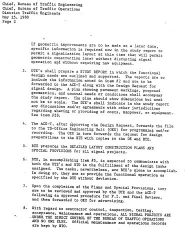
148 Page 11-3
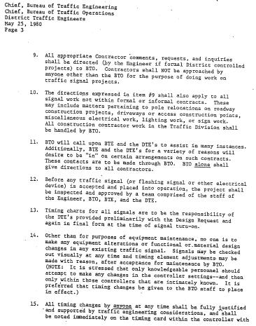
149 Page 11-4
150 Page 11-5
151 Page 11-6
152 Page 11-7
153 B. SHA Policy for Determining Yellow Timing at Intersections Page 11-8
154 Page 11-9

155 Page 11-10
156 Page 11-11
157 Page 11-12
158 Page 11-13
159 Page 11-14

160 Page 11-15

161 Page 11-16

162 Page 11-17

163 Page 11-18
164 C. SHA Part-Time Signal Operation Worksheet Page 11-19
165 Page 11-20

166 D. SHA Signal Timing Chart Page 11-21

167 Page 11-22

168 Page 11-23

169 Page 11-24

170 Page 11-25

171 Page 11-26

172 Page 11-27

173 Page 11-28

174 Page 11-29
175 Page 11-30
176 E. SHA Capacity Procedures for Intersections Critical Lane and Queuing Analysis Page 11-31
177 Page 11-32
178 Page 11-33
179 Page 11-34
180 Page 11-35
181 Page 11-36
182 Page 11-37
183 Page 11-38
184 Page 11-39
185 F. Isolated Intersection Signal Timing Checklist ISOLATED INTERSECTION SIGNAL TIMING CHECKLIST Main Road Side Road County District Observed By Speed Limit (Major) Speed Limit (Side) Date Time 1. Do queues clear each cycle? Yes / No if no, specify 2. Do phases max out or gap out each cycle? 3. Do left-turn or right-turn queues extend beyond storage? Yes / No if yes, specify 4. Do through queues block the turn bays? Yes / No if yes, specify 5. Are detection devices functioning properly? Yes / No if no, specify 6. Are phases recalled even if demand is not present? If so, are there false calls or are the recalls programmed? Yes / No if yes, specify 7. Are signals functioning properly? Yes / No if no, specify 8. What is the main road and side road signal phasing (e.g., permissive only, exclusive/permissive, exclusive, split)? 9. Does the exclusive portion of the exclusive/permissive phase(s) need additional green time? Yes / No if yes, specify 10. Are signal heads aligned properly? Yes / No if no, specify 11. Are all pedestrian timings adequate and are the pedestrian indications functioning properly? Yes / No if no, specify 12. What are the field-measured crosswalk distances? 13. Is the push-button device easily accessible and functional? Yes / No if no, specify 14. Are the APS features functioning properly? Yes / No if no, specify 15. Is the timing chart available? Yes / No if no, specify 16. Do the controller settings match the timing chart? Yes / No if no, specify 17. Are all pavement markings adequate? Yes / No if no, specify 18. Are overhead street name signings adequate? Yes / No if no, specify 19. Are there route markers and advance warning signs on the approaches? Yes / No if no, specify 20. Is the intersection lighting functioning properly? Yes / No if no, specify 21. Should part-time flashing signal operation be adjusted? Yes / No if yes, specify 22. General operation of the signal: Are there any perceived safety problems/conflicts? Are nearby access points/driveways impacted by traffic at the signal? Comments: Page 11-40
186
187
188 GLOSSARY Actuated control (fully-actuated control) A type of signal operation in which all of the signal phases function on the basis of detection. Added initial A volume-density interval that times concurrently with the minimum green interval and increases by each vehicle actuation received during the associated yellow and red intervals. This time cannot exceed the maximum initial. Advance preemption The notification of approaching rail traffic is forwarded to the highway traffic signal controller prior to the activation of the railroad or light rail transit warning devices. Advance warning flasher A specific type of active hazard identification beacon that is installed upstream of a conventional traffic signal to warn approaching motorists prior to the onset of the yellow change interval. The assemblies typically include a flashing RED SIGNAL AHEAD sign or a SIGNAL AHEAD PREPARE TO STOP WHEN FLASHING sign with yellow warning beacons. Advanced pedestrian phase (leading pedestrian phase) A type of pedestrian walk interval that begins several seconds prior to the vehicular phase for the adjacent vehicular movements to allow pedestrians to establish a presence in the crosswalk and to reduce conflicts with concurrent turning vehicles. Alternate sequence A time-of-day signal controller parameter that modifies the signal sequence by reversing the order in which pairs of phases, e.g., phases 1 and 2 or phases 3 and 4, are serviced. Alternate vehicle extension (alternate passage time) A time-of-day signal controller parameter that enables the use of the auxiliary vehicle extension interval to increase or decrease the preset gap during a specific time period, such as school arrival and dismissal periods. Barrier The separation of intersecting movements to prevent operating conflicting phases simultaneously. Call An indication within a signal controller that a vehicle or pedestrian is awaiting service from a particular phase or that a recall has been placed on the phase. Capacity The maximum sustainable flow rate at which vehicles or persons reasonably can be expected to traverse a point or uniform segment of a lane or roadway during a specified time period under given roadway, geometric, traffic, environmental, and control conditions. Concurrent phasing (simultaneous phasing) Two or more phases in separate rings that operate together without conflicting movements. Conditional phase (lead plus lag phase or phase re-servicing) Servicing a left-turn phase twice per cycle, first as a lead phase and then as a lag phase, when the opposing through phase terminates early and the through phase in the same direction is still being serviced. Coordinated-actuated A type of signal operation that allows a coordinated phase to operate with a preset minimum split that can be extended each cycle using passage detection and the corresponding vehicle extension interval. Critical lane volume A simplified capacity analysis methodology that can be used to determine basic signal timing parameters, such as the maximum green interval, split, and cycle length. Cycle length The time required for one complete sequence of signal indications.
189 Delay Travel time delay: The additional travel time experienced by a driver, passenger, or pedestrian. Detector delay: A detector parameter, typically used with presence detection for turning movements from exclusive lanes, used to temporarily postpone a call for a phase. Demand The number of users desiring service on the highway system. Detector cross switching A setting that allows a detector to be assigned to different phases each cycle by initially assigning the detector to a phase then changing the phase assignment later in the signal sequence. Detector phase assignment A signal controller setting that allows each vehicle detector to be designated to any or all of the twelve phases and place a call on the designated phase(s). Detector type A signal controller setting that classifies each detector, such as normal/standard, extend/delay, stop bar, calling, bike, dilemma zone, or walk. Early green A term used to describe servicing a coordinated phase prior to its programmed offset as a result of unused time from non-coordinated phases. Exclusive phase (protected phase) A mode in which left or right turns are permitted when a left or right green arrow signal indication is displayed. Exclusive/permissive phase (protected/permitted phase) A combined left-turn treatment that displays the exclusive phase before the permissive phase. Exit maximum times The maximum green intervals in effect for one cycle following a preemption sequence for all phases except the hold phases. This parameter is intended to clear queues at the end of a preemption routine. Exit phases The phases serviced at the end of a preemption sequence that serve as transition phases to return to standard signal operations. Gap out When an actuated phase terminates prior to its maximum green time due to a lack of calls within the vehicle extension time. Gap reduction A volume-density feature that reduces the vehicle extension time to a smaller value while the phase is active. Greenband (bandwidth) The maximum amount of green time for a designated direction as it passes through a coordinated signal system at an assumed constant speed. Half cycle length (double cycling) A cycle length that allows phases to be serviced twice as often as other intersections in the coordinated signal system. Hold phases The phases that remain in service during preemption until the hold time expires or until the preemption call is dropped. Inductive loop An intrusive type of vehicle detection that can be used for presence and passage detection. The detectors are formed by sawcutting the roadway, placing a #14 AWG wire incased in flexible tubing into the sawcut, and then sealing the sawcut. Lag phase An exclusive left-turn phase that operates concurrently with the through phase in the same direction and that is sequenced after the opposing through phase.
190 Lead phase An exclusive left-turn phase that operates concurrently with the through phase in the same direction and that is sequenced before the opposing through phase. Lead/lag phasing A left-turn treatment where one left-turn movement begins with the adjacent through phase and then the opposing left-turn movement begins at the end of the opposing through phase. Leading flash time (AWF overlap interval) The time prior to the onset of the yellow change interval that the advance warning flasher is activated to warn approaching motorists of the upcoming phase termination. Locking memory A controller mode used to place a call for service after the first actuation is received by the controller during the red interval. The controller retains the call even if the vehicle departs the detection zone. Master-slave system (relay based system) A signal system that consists of two intersections hardwired together with an interconnect cable, where one intersection operates fully-actuated and corresponding holds/controls phases at the adjacent intersection. Max extension A signal controller parameter that will automatically increase the maximum green interval if a phase terminates due to max out during two successive cycles. Max out When an actuated phase terminates at its preset maximum green time. Maximum green interval The maximum time a phase can be green in the presence of a conflicting call. Microloop probe A small, cylindrical, passive transducer that is placed underneath the roadway in a nonmetallic conduit and that detects vehicles by sensing disruptions in the earth s magnetic field. Minimum gap A volume-density parameter that specifies the minimum vehicle extension when gap reduction is used. Minimum green interval The first timed portion of the green interval which may be set in consideration of driver expectancy or based on the storage of vehicles between the detectors and the stop line. Model 170 controller A type of signal controller that contains a user-programmable microprocessor instead of a standard NEMA ring-and-barrier structure. NEMA phasing (National Electrical Manufacturers Association phasing) A common ringand-barrier controller structure that organizes phases by prohibiting conflicting movements from timing concurrently while allowing non-conflicting movements to operate simultaneously. Non-interconnected system (time-based coordinated) A basic type of signal system consisting of two or more signalized intersections coordinated solely by time. Non-locking memory A controller mode that retains a call for service only while the vehicle remains within the detection zone. Offset The time relationship between coordinated phases defined reference point (typically the beginning of green) and a defined master reference. On-street master An optional component of a coordinated signal system that facilitates coordination with the use of a local controller instead of a remote, central-based computer.
191 Opticom TM A common type of preemption system that uses a visible light and/or infrared vehicle emitter and a receiver located adjacent to the traffic signal heads to identify and detect emergency vehicles. Overlap phase A green indication allowing two or more non-conflicting traffic phases to operate simultaneously. Passage detector (pulse detector) A type of detection where vehicle actuations are represented by a single on pulse to the controller. Peak hour factor A measure of the fluctuation in the demand within the peak hour. Pedestrian clearance interval An interval during which the flashing upraised hand (symbolizing don t walk) pedestrian signal indication is displayed. Pedestrian walk interval An interval during which the walking person (symbolizing walk) pedestrian signal indication is displayed. Permissive phase (permitted phase) A mode in which left or right turns are permitted after yielding to pedestrians and/or opposing traffic. Phase A signal controller timing unit associated with the control of one or more movements. Phase omit A command, typically used during preemption or alternate sequences, which causes the exclusion of a selected phase. Phase sequence The order of a series of phases. Preemption The transfer of normal signal operations to a special control mode. Preemption delay The time between the receipt of the preemption call and the initialization of the preemption phases/sequence. Presence detector A type of detection where vehicle actuations are sent to the controller only while a vehicle is within the detection zone. Pre-timed control A type of signal operation in which the phase sequence, green times, and cycle length are preset to repeat continuously. Progression (coordination) The ability to synchronize multiple signalized intersections to enhance the operation of one or more movements in a signal system. Queue A line of vehicles, bicycles, or persons waiting to be served by the system. Queue detector A type of detector that is typically placed along freeway off-ramps upstream of signalized intersections to detect the presence of queued vehicles and to place a call on the signal controller to modify signal timings to prevent queues from extending back onto the freeway. Recall A repetitive call that is placed for a specified phase each time the controller is servicing a conflicting phase to ensure that the specified phase will be serviced each cycle. Types of recall include soft, minimum, maximum, and pedestrian. Red clearance interval An interval that follows the yellow change interval and precedes the next conflicting green interval. Ring A series of conflicting phases that operate sequentially. Running time The portion of the travel time during which the vehicle is in motion.
192 Sampling detector (system detector) A type of detection that is placed downstream of signalized intersections to collect free flow traffic data, such as volume, speed, and occupancy. Saturation flow rate The equivalent hourly rate, in vehicles per hour per lane, at which vehicles can depart an intersection under prevailing conditions, assuming a constant green indication at all time and no lost time. Semi-actuated control A type of signal operation in which at least one, but not all, signal phases function on the basis of detection. Simultaneous preemption The notification of approaching rail traffic is forwarded to the highway traffic signal controller and railroad or light rail transit active warning devices at the same time. Split The time, expressed in seconds or percentage of the cycle length, assigned to a phase, typically the green plus yellow and all-red intervals, during coordinated signal operations. Split demand A signal controller function that can automatically change signal patterns to favor specific phases when excessive queues are detected along the approach. Split phasing (separate phasing) A type of exclusive phasing where opposing approaches operate separately, rather than simultaneously. Adjacent turning and through movements on the same approach operate simultaneously with this type of signal phasing. Telemetry system A signal system consisting of two or more intersections that are interconnected by a two-way communication system, and signal coordination is controlled by either an on-street master controller or a central-based computer. Time before reduction A volume-density timing period that begins when the phase is green and when there is a serviceable call on a conflicting phase. When this period expires, the linear reduction of the vehicle extension begins. Time-space diagram A chart that plots the location of signalized intersections along the vertical axis and signal timing intervals along the horizontal axis to serves as a visual tool for the coordination relationships among intersections. Time to reduce A volume-density timing period that begins when the time before reduction ends and that controls the linear rate of reduction of the vehicle extension until the minimum gap is achieved. Traffic adaptive A signal system control method where vehicles are detected at points upstream and/or downstream of signalized intersections and an algorithm is used to make automatic real-time signal timing adjustments. Traffic responsive A signal system control method which uses data from traffic detectors, rather than time-of-day information, to automatically select a preset timing plan best suited to current traffic conditions. Travel time The total elapsed time spent traversing a specified distance. V/C ratio (degree of saturation) The ratio of volume to capacity for a subject movement. Vehicle extension (passage time) A phase timer that terminates an actuated phase when the time between detector actuations exceeds the timer setting. Video detection A type of detection that uses video imaging to detect vehicles within a
193 camera s field of view and predetermined detection zone. Volume The number of persons or vehicles passing a point on a lane, roadway, or other travel way during a specific time interval. Volume-density A type of actuated signal operation that incrementally increases the minimum green time based on actual traffic demand and that linearly reduces the vehicle extension time as the phase continues to time. Yellow change interval The first interval following the green or flashing arrow interval during which the steady yellow signal indication is displayed.
194 REFERENCES Advanced System Controller ASC/2 Family Programming Manual, Econolite Control Products, Inc., Fundamentals of Traffic Engineering, 15th Edition, Institute of Transportation Studies University of California, Berkeley, Highway Capacity Manual, Transportation Research Board, Manual of Traffic Signal Design, Institute of Transportation Engineers, Manual of Transportation Engineering Studies, Institute of Transportation Engineers, Manual on Uniform Traffic Control Devices for Streets and Highways, 2003 and 2009 Editions, Federal Highway Administration. Maryland Manual on Uniform Traffic Control Devices for Streets and Highways, 2006 Edition, Maryland State Highway Administration, Mn/DOT Traffic Signal Timing and Coordination Manual, Minnesota Department of Transportation, Signalized Intersections: Informational Guide, Federal Highway Administration, State Highway Access Manual, Maryland State Highway Administration, Traffic Control Device Application Guidelines Manual, Maryland State Highway Administration. Traffic Control Devices Design Manual, Maryland State Highway Administration, Traffic Detector Handbook, Third Edition, Federal Highway Administration, Traffic Engineering, Third Edition, Polytechnic University, Traffic Engineering Handbook, Institute of Transportation Engineers, Traffic Operations Manual: Railroad Operations Volume, Texas Department of Transportation, Traffic Signal Timing Manual, Institute of Transportation Engineers, Traffic Signal Workshop, Northwestern University, 2005.
195
196
Chapter 5 5. INTERSECTIONS 5.1. INTRODUCTION
 Chapter 5 5. INTERSECTIONS 5.1. INTRODUCTION Intersections are the physical component of the roadways where two highways intersect. They are the most complex element of roadways, since it requires more
Module 3 Developing Timing Plans for Efficient Intersection Operations During Moderate Traffic Volume Conditions
 Module 3 Developing Timing Plans for Efficient Intersection Operations During Moderate Traffic Volume Conditions CONTENTS (MODULE 3) Introduction...1 Purpose...1 Goals and Learning Outcomes...1 Organization
Traffic Signal Optimization Project (Hosman Road) (Future Coordinated Corridor)
 (Future Coordinated Corridor)") Onondaga County Department of Transportation Traffic Signal Optimization Project (Hosman Road) (Future Coordinated Corridor) Prepared for: Syracuse Metropolitan Transportation Council 126 North Salina
Onondaga County Department of Transportation Traffic Signal Optimization Project (Hosman Road) (Future Coordinated Corridor) Prepared for: Syracuse Metropolitan Transportation Council 126 North Salina
Actuated Signal Timing Design CIVL 4162/6162
 Actuated Signal Timing Design CIVL 4162/6162 Session Objective Explain terms related to actuated signals Explain why and where actuated signals are used Determine detector locations given traffic conditions
Signal Timing Design CIVL 4162/6162
 Signal Timing Design CIVL 4162/6162 Summary of Signal Design Signal Phase Plans Treatment of Left Turns General Considerations Phase and Ring Diagrams Common Phase Plans and Their Use Vehicular Needs Change
Chapter Capacity and LOS Analysis of a Signalized I/S Overview Methodology Scope Limitation
 Chapter 37 Capacity and LOS Analysis of a Signalized I/S 37.1 Overview The Highway Capacity Manual defines the capacity as the maximum howdy rate at which persons or vehicle can be reasonably expected
Washington St. Corridor Study
 FIGURE 7.17 Bridge Alternatives - Cross Sections 86 Discarded Alternative: Short-Term Bridge Repair Short-term repairs and west bridge span replacement were considered during analysis. Short-term repairs
Arterial Traffic Analysis Actuated Signal Control
 Arterial Traffic Analysis Actuated Signal Control Dr. Gang-Len Chang Professor and Director of Traffic Safety and Operations Lab. University of Maryland-College Park Actuated Signal Control Fully Actuated
INDUSTRIAL BUILDING 3009 HAWTHORNE ROAD CITY OF OTTAWA TRANSPORTATION OVERVIEW REVISED. Prepared for: Canada Inc.
 INDUSTRIAL BUILDING 3009 HAWTHORNE ROAD CITY OF OTTAWA TRANSPORTATION OVERVIEW REVISED Prepared for: 7849648 Canada Inc. Octiober 1, 2015 114-598 Overview_2.doc D. J. Halpenny & Associates Ltd. Consulting
6. signalized Intersections
 6. signalized Intersections 1 References 1. HCM 2000, chapter 16 2. safety.fhwa.dot.gov/intersection/signalized/sig_int_pps051508 /short/sigint_short.ppt 3. mason.gmu.edu/~aflaner/ceie_360/signalized%20intersectio
METHODOLOGY. Signalized Intersection Average Control Delay (sec/veh)
") Chapter 5 Traffic Analysis 5.1 SUMMARY US /West 6 th Street assumes a unique role in the Lawrence Douglas County transportation system. This principal arterial street currently conveys commuter traffic
Chapter 5 Traffic Analysis 5.1 SUMMARY US /West 6 th Street assumes a unique role in the Lawrence Douglas County transportation system. This principal arterial street currently conveys commuter traffic
OFFICE/RETAIL DEVELOPMENT 1625 BANK STREET OTTAWA, ONTARIO TRANSPORTATION BRIEF. Prepared for: Canada Inc.
 OFFICE/RETAIL DEVELOPMENT 1625 BANK STREET OTTAWA, ONTARIO TRANSPORTATION BRIEF Prepared for: 9402209 Canada Inc. December 15, 2015 115-625 Report_2.doc D. J. Halpenny & Associates Ltd. Consulting Transportation
Existing Conditions. Date: April 16 th, Dan Holderness; Coralville City Engineer Scott Larson; Coralville Assistant City Engineer
 Date: April 16 th, 2015 To: From: Re: Dan Holderness; Coralville City Engineer Scott Larson; Coralville Assistant City Engineer Darian Nagle-Gamm, Traffic Engineering Planner Highway 6 (2 nd Street) /
Evaluation of M-99 (Broad Street) Road Diet and Intersection Operational Investigation
 Road Diet and Intersection Operational Investigation") Evaluation of M-99 (Broad Street) Road Diet and Intersection Operational Investigation City of Hillsdale, Hillsdale County, Michigan June 16, 2016 Final Report Prepared for City of Hillsdale 97 North Broad
Evaluation of M-99 (Broad Street) Road Diet and Intersection Operational Investigation City of Hillsdale, Hillsdale County, Michigan June 16, 2016 Final Report Prepared for City of Hillsdale 97 North Broad
Traffic Study North Shore School District 112
 Traffic Study North Shore School District 112 Proposed Expansion of Northwood Junior High School Prepared By: May 1, 2015 1. Introduction Kenig, Lindgren, O Hara, Aboona, Inc. (KLOA, Inc.) has been retained
TRANSPORTATION ANALYSIS REPORT US Route 6 Huron, Erie County, Ohio
 TRANSPORTATION ANALYSIS REPORT US Route 6 Huron, Erie County, Ohio December 12, 2012 Prepared for: The City of Huron 417 Main Huron, OH 44839 Providing Practical Experience Technical Excellence and Client
Introduction to Traffic Signal Timing
 Introduction to Traffic Signal Timing Course No: C-7 Credit: PDH Jeffrey W. Buckholz, Ph.D., P.E., PTOE Continuing Education and Development, Inc. 9 Greyridge Farm Court Stony Point, NY 98 P: (877) -58
Synchro Studio 8. Overview. By Ioannis Psarros
 Synchro Studio 8 Overview By Ioannis Psarros What is Synchro? Software for signal optimization Developed by Trafficware Optimization can be applied to: Cycle lengths Splits Offsets Source: http://bikewalklee.blogspot.com
MUTCD Part 6G: Type of Temporary Traffic Control Zone Activities
 MUTCD Part 6G: Type of Temporary Traffic Control Zone Activities 6G.01 Typical Applications Each temporary traffic control (TTC) zone is different. Many variables, such as location of work, highway type,
Traffic Signal Design
 Traffic Signal Design Instructor: S. M. Mahdi Amiripour m.amiripour@gmail.com 2 Introduction Intersection is an area shared by two or more roads Designated for the vehicles to turn to different directions
Traffic Circulation Study for Neighborhood Southwest of Mockingbird Lane and Airline Road, Highland Park, Texas
 ARIZONA TEXAS NEW MEXICO OKLAHOMA February 13, 2015 Mr. Meran Dadgostar P.E., R.S. Town of Highland Park 4700 Drexel Dr. Highland Park, Texas 75205 Re: Traffic Circulation Study for Neighborhood Southwest
Section 400 Signal Design. Engineering Branch
 Section 400 Signal Design Engineering Branch December 2003 TABLE OF CONTENTS 400 SIGNAL DESIGN 401 INTRODUCTION... 1 401.1 About Section 400... 1 401.2 Before You Begin... 1 402 TRAFFIC SIGNALS... 3 402.1
ENHANCED PARKWAY STUDY: PHASE 2 CONTINUOUS FLOW INTERSECTIONS. Final Report
 Preparedby: ENHANCED PARKWAY STUDY: PHASE 2 CONTINUOUS FLOW INTERSECTIONS Final Report Prepared for Maricopa County Department of Transportation Prepared by TABLE OF CONTENTS Page EXECUTIVE SUMMARY ES-1
Traffic Impact Analysis Chatham County Grocery Chatham County, NC
 Chatham County Grocery Chatham County, NC TABLE OF CONTENTS 1. INTRODUCTION... 1 1.1. Location and Study Area... 1 1.2. Proposed Land Use and Access... 2 1.3. Adjacent Land Uses... 2 1.4. Existing ways...
2009 PE Review Course Traffic! Part 1: HCM. Shawn Leight, P.E., PTOE, PTP Crawford Bunte Brammeier Washington University
 2009 PE Review Course Traffic! Part 1: HCM Shawn Leight, P.E., PTOE, PTP Crawford Bunte Brammeier Washington University sleight@cbbtraffic.com Topic Areas Highway Capacity Manual Highway Capacity Analysis
INDUSTRIAL BUILDING 1660 COMSTOCK ROAD CITY OF OTTAWA TRANSPORTATION OVERVIEW. Prepared for:
 INDUSTRIAL BUILDING 1660 COMSTOCK ROAD CITY OF OTTAWA TRANSPORTATION OVERVIEW Prepared for: Simluc Contractors Limited 2550 Blackwell Street, Ottawa K1B 5R1 October 18, 2013 113-584 Overview_1.doc D. J.
MEMORANDUM. Charlotte Fleetwood, Transportation Planner
 MEMORANDUM Date: Updated August 22, 2017 To: Organization: Charlotte Fleetwood, Transportation Planner Boston Transportation Department From: Jason DeGray, P.E., PTOE, Regional Director of Engineering
QUICKIE C STORE AND GAS BAR 1780 HERON ROAD OTTAWA, ONTARIO TRANSPORTATION BRIEF. Prepared for:
 QUICKIE C STORE AND GAS BAR 1780 HERON ROAD OTTAWA, ONTARIO TRANSPORTATION BRIEF Prepared for: Quickie Convenience Stores Larny Holdings Ltd. c/o PBC Group April 15, 2015 115-615 Report_1.doc D. J. Halpenny
Traffic Signals. Part I
 Traffic Signals Part I Part I The Islamic University of Gaza Civil Engineering Department Traffic Engineering (Optional Course) ECIV 5332 Instructor: Dr. Yahya Sarraj Associate Prof. in Transportation
TABLE OF CONTENTS. 1 Overview Introduction Timing Goals Review of Signal Timing
 June 2015 TABLE OF CONTENTS 1 Overview... 1 1 1.1 Introduction... 1 1 1.2 Timing Goals... 1 1 Review of Signal Timing... 1 1 2 Data Collection and Information Needed... 2 1 2.1 Data Collection... 2 1
URBAN STREET CONCEPTS
 CHAPTER 10 URBAN STREET CONCEPTS CONTENTS I. INTRODUCTION... 10-1 II. URBAN STREETS...10-1 Flow Characteristics... 10-3 Free-Flow Speed...10-3 Running Speed... 10-3 Travel Speed... 10-4 Time-Space Trajectory...10-4
Traffic Impact Study WestBranch Residential Development Davidson, NC March 2016
 Traffic Impact Study WestBranch Residential Development Davidson, NC March 216 TRAFFIC IMPACT STUDY FOR THE WestBranch Residential Development LOCATED IN DAVIDSON, NC Prepared For: Lennar Carolinas, LLC
REDEVELOPMENT TRAFFIC IMPACT STUDY
 REDEVELOPMENT TRAFFIC IMPACT STUDY For Wendy s Parker, Colorado January 215 Prepared for: Sterling Design Associates, LLC 29 W. Littleton Boulevard #3 Littleton, Colorado 812 Prepared by: 1233 Airport
6060 North Central Expressway Mixed-Use Site Dallas, Texas
 Volume 1 Traffic Impact Analysis 6060 North Central Expressway Mixed-Use Site Dallas, Texas April 30, 2018 Kimley-Horn and Associates, Inc. Dallas, Texas Project #063238300 Registered Firm F-928 Traffic
Traffic Impact Study. Westlake Elementary School Westlake, Ohio. TMS Engineers, Inc. June 5, 2017
 TMS Engineers, Inc. Traffic Impact Study Westlake Elementary School Westlake, Ohio June 5, 2017 Prepared for: Westlake City Schools - Board of Education 27200 Hilliard Boulevard Westlake, OH 44145 TRAFFIC
Traffic Impact Analysis Walton Acres at Riverwood Athletic Club Clayton, NC
 Traffic Impact Analysis Walton Acres at Riverwood Athletic Club Clayton, NC 1. TABLE OF CONTENTS INTRODUCTION...1 1.1. Site Location and Study Area...1 1.2. Proposed Land Use and Site Access...2 1.3.
Strategies to Re capture Lost Arterial Traffic Carrying Capacities
 Strategies to Re capture Lost Arterial Traffic Carrying Capacities Chalap K. Sadam, P.E. and Albert L. Grover, P.E. Over the years, many arterials that were initially designed to carry tens of thousands
ALLEY 24 TRAFFIC STUDY
 ALLEY 24 TRAFFIC STUDY in City of Frostburg, Maryland January 2013 3566 Teays Valley Road Hurricane, WV Office: (304) 397-5508 www.denniscorporation.com Alley 24 Traffic Study January 2013 Frostburg, Maryland
THE FUTURE OF THE TxDOT ROADWAY DESIGN MANUAL
 THE FUTURE OF THE TXDOT ROADWAY DESIGN MANUAL Kenneth Mora, P.E. (Design Division) 10/10/2017 Table of contents 1 2 Reduction in FHWA design controlling criteria Innovative Intersection Guidance 3-7 8-42
Design of Turn Lane Guidelines
 Design of Turn Lane Guidelines CTS Transportation Research Conference May 24, 2012 Howard Preston, PE Minnesota Department of Transportation Research Services Office of Policy Analysis, Research & Innovation
Intersection of Massachusetts Avenue and Maple Street in Lexington Signalized Intersection and Roundabout Comparison
 Intersection of Massachusetts Avenue and Maple Street in Lexington Signalized Intersection and Roundabout Comparison Michael Wallwork, Roundabout Expert, Orange Park, Florida Tom Bertulis (MS, PE, PTOE),
APARTMENT BUILDING DEVELOPMENT 1161 HERON ROAD OTTAWA, ONTARIO TRANSPORTATION IMPACT STUDY. Prepared for:
 APARTMENT BUILDING DEVELOPMENT 1161 HERON ROAD OTTAWA, ONTARIO TRANSPORTATION IMPACT STUDY Prepared for: 1649362 Ontario Inc. c/o Manor Park Management 231 Brittany Drive, Suite D Ottawa ON K1K 0R8 July
FORM A PASCO COUNTY ACCESS CONNECTION PERMIT APPLICATION
 FORM 901.3.A PASCO COUNTY ACCESS CONNECTION PERMIT APPLICATION The following information is required from all applicants directly or indirectly accessing any collector or arterial road or as otherwise
Traffic Impact Study Little Egypt Road Development Denver, North Carolina June 2017
 Traffic Impact Study Little Egypt Road Development Denver, North arolina June 2017 N. Little Egypt Road DQ\ QDQFLQJ VDOHV RU RWKHU SHUIRUPDQFH EDVHG FULWHULD Proposed Site Driveways Site Driveway 1 TRAFFI
Chapter 4 Traffic Analysis
 Chapter 4 Traffic Analysis PURPOSE The traffic analysis component of the K-68 Corridor Management Plan incorporates information on the existing transportation network, such as traffic volumes and intersection
SIDRA INTERSECTION 6.1 UPDATE HISTORY
 Akcelik & Associates Pty Ltd PO Box 1075G, Greythorn, Vic 3104 AUSTRALIA ABN 79 088 889 687 For all technical support, sales support and general enquiries: support.sidrasolutions.com SIDRA INTERSECTION
Glenn Avenue Corridor Traffic Operational Evaluation
 Glenn Avenue Corridor Traffic Operational Evaluation PREPARED FOR: THE CITY OF AUBURN PREPARED BY: DECEMBER 2007 Glenn Avenue Corridor Study--Auburn, Alabama TABLE OF CONTENTS Introduction... 1 Background
2014 FHWA Aging Road User Handbook. Recommendations to Accommodate Aging Pedestrians. Lifesaver National Conference. What is the Handbook?
 2014 FHWA Aging Road User Handbook Recommendations to Accommodate Aging Pedestrians Lifesaver National Conference March 17, 2015 Revised June 2014 1 What is the Handbook? 1998 1st Edition 2001 2nd Edition
I-95 Northbound at US 1 (Exit 126) Design and Study Final Report
 Design and Study Final Report") I-95 Northbound at US 1 (Exit 126) Design and Study Final Report July 2018 Prepared by: Prepared for: TABLE OF CONTENTS 1 Introduction... 1 Study Area Limits... 1 Purpose and Need of the Study... 1 Safety
I-95 Northbound at US 1 (Exit 126) Design and Study Final Report July 2018 Prepared by: Prepared for: TABLE OF CONTENTS 1 Introduction... 1 Study Area Limits... 1 Purpose and Need of the Study... 1 Safety
FINAL DESIGN TRAFFIC TECHNICAL MEMORANDUM
 FINAL DESIGN TRAFFIC TECHNICAL MEMORANDUM July 2014 FINAL (SR 43) Project Development and Environment Study From State Road 60 (Adamo Drive) to I-4 (SR 400) Hillsborough County, Florida Work Program Item
THIS PAGE LEFT BLANK INTENTIONALLY
 GA SR 25 Spur at Canal Road Transportation Impact Analysis PREPARED FOR GLYNN COUNTY, GEORGIA 1725 Reynolds Street, Suite 300 Brunswick, Georgia 31520 PREPARED BY 217 Arrowhead Boulevard Suite 26 Jonesboro,
TRAFFIC ASSESSMENT River Edge Colorado
 TRAFFIC ASSESSMENT River Edge Colorado Submitted by: Fehr & Peers 621 17th Street, Ste. 231 Denver, CO 8293 (33) 296-43 December, 21 App. M-2 Traffic Assessment River Edge Colorado December 21 TABLE OF
Arterial Traffic Analysis Some critical concepts. Prepared by Philip J. Tarnoff
 Arterial Traffic Analysis Some critical concepts Prepared by Philip J. Tarnoff Agenda Fundamentals Signal timing concepts Actuated signal controllers Developing timing plans Types of signal control First
Operation, Analysis, and Design of Signalized Intersections
 Operation, Analysis, and Design of Signalized Intersections A Module for the Introductory Course in Transportation Engineering Michael Kyte Maria Tribelhorn University of Idaho 2014.01.04 ii 2014.01.02
TRAFFIC SIGNAL WARRANT STUDY
 TRAFFIC SIGNAL WARRANT STUDY 5 th STREET & ENCHANTED PINES DRIVE JANUARY 2013 TRAFFIC OPERATIONS ENGINEERING SERVICES/PUBLIC WORKS DEPARTMENT TABLE OF CONTENTS INTERSECTION LOCATION MAP ii INTRODUCTION
Access Location, Spacing, Turn Lanes, and Medians
 Design Manual Chapter 5 - Roadway Design 5L - Access Management 5L-3 Access Location, Spacing, Turn Lanes, and Medians This section addresses access location, spacing, turn lane and median needs, including
ANALYSIS OF SIGNALISED INTERSECTIONS ACCORDING TO THE HIGHWAY CAPACITY MANUAL FROM THE POINT OF VIEW OF THE PROCESSES APPLIED IN HUNGARY
 2nd Int. Symposium in Civil Engineering 1998 Budapest ANALYSIS OF SIGNALISED INTERSECTIONS ACCORDING TO THE HIGHWAY CAPACITY MANUAL FROM THE POINT OF VIEW OF THE PROCESSES APPLIED IN HUNGARY István Styevola
THE INSTALLATION OF PRE-SIGNALS AT RAILROAD GRADE CROSSINGS
 THE INSTALLATION OF PRE-SIGNALS AT RAILROAD GRADE CROSSINGS Lisa D. Sherman, Kenneth J. Petraglia, P.E. INTRODUCTION Each signalized intersection adjacent to a highway-rail grade crossing presents the
MEDICAL/OFFICE BUILDING 1637 BANK STREET OTTAWA, ONTARIO TRANSPORTATION OVERVIEW. Prepared for:
 MEDICAL/OFFICE BUILDING 1637 BANK STREET OTTAWA, ONTARIO TRANSPORTATION OVERVIEW Prepared for: 2434984 Ontario Inc. 13-5510 Canotek Road Ottawa, Ontario K1J 9J5 June 4, 2015 115-613 Report_2.doc D. J.
An Evaluation of Signalized Intersection System Analysis Techniques Walter J. Freeman, P.E., Kien Y. Ho, P.E., Elizabeth A. McChesney, E.I.T.
 An Evaluation of Signalized Intersection System Analysis Techniques Walter J. Freeman, P.E., Kien Y. Ho, P.E., Elizabeth A. McChesney, E.I.T. A system of signalized intersections is a critical element
TECHNIQUES TO IMPROVE SAFETY AND OPERATIONS AT SIGNALIZED DIAMOND INTERCHANGES IN NEVADA
 TECHNIQUES TO IMPROVE SAFETY AND OPERATIONS AT SIGNALIZED DIAMOND INTERCHANGES IN NEVADA FINAL REPORT Prepared for Nevada Department of Transportation Authors Zong Z. Tian, PhD, PE Ahmed Abdel Dayem Department
DUNBOW ROAD FUNCTIONAL PLANNING
 DUNBOW ROAD FUNCTIONAL PLANNING Final Report August 3, 216 #31, 316 5th Avenue NE Calgary, AB T2A 6K4 Phone: 43.273.91 Fax: 43.273.344 wattconsultinggroup.com Dunbow Road Functional Planning Final Report
HILTON GARDEN INN HOTEL HOTEL EXPANSION 2400 ALERT ROAD, OTTAWA TRANSPORTATION BRIEF. Prepared for:
 HILTON GARDEN INN HOTEL HOTEL EXPANSION 2400 ALERT ROAD, OTTAWA TRANSPORTATION BRIEF Prepared for: Bona Building & Management Co. Ltd. Place Vanier, 333 North River Road Vanier, Ontario K1L 8B9 October
Project Report. South Kirkwood Road Traffic Study. Meadows Place, TX October 9, 2015
 Meadows Place, TX October 9, 2015 Contents 1 Introduction... 1 2 Data Collection... 1 3 Existing Roadway Network... 2 4 Traffic Volume Development... 2 5 Warrant Analysis... 3 6 Traffic Control Alternative
OTTAWA TRAIN YARDS PHASE 3 DEVELOPMENT CITY OF OTTAWA TRANSPORTATION IMPACT STUDY. Prepared for:
 OTTAWA TRAIN YARDS PHASE 3 DEVELOPMENT CITY OF OTTAWA TRANSPORTATION IMPACT STUDY Prepared for: The Ottawa Train Yards Inc. 223 Colonnade Road South, Suite 212 Nepean, Ontario K2E 7K3 January 17, 2012
VIVA RETIREMENT COMMUNITIES OAKVILLE TRAFFIC IMPACT STUDY
 VIVA RETIREMENT COMMUNITIES OAKVILLE TRAFFIC IMPACT STUDY VIVA RETIREMENT COMMUNITIES OAKVILLE TRAFFIC IMPACT STUDY DECEMBER 2012 READ, VOORHEES & ASSOCIATES TORONTO, ONTARIO Read, Voorhees & Associates
3.9 - Transportation and Traffic
 Transportation and Traffic 3.9 - Transportation and Traffic This section describes the potential transportation and traffic effects of project implementation on the project site and its surrounding area.
MEETING FACILITY 2901 GIBFORD DRIVE CITY OF OTTAWA TRANSPORTATION BRIEF. Prepared for: Holiday Inn Express 2881 Gibford Drive Ottawa, ON K1V 2L9
 MEETING FACILITY 2901 GIBFORD DRIVE CITY OF OTTAWA TRANSPORTATION BRIEF Prepared for: Holiday Inn Express 2881 Gibford Drive Ottawa, ON K1V 2L9 December 18, 2012 112-566 Brief_1.doc D. J. Halpenny & Associates
Place Vanier 250 Montreal Road Transportation Impact Study Addendum. Prepared for Broccolini Construction September 20 th, 2012
 Update for the May 31 st, 2012 Traffic Impact Study Prepared for Broccolini Construction 111-23596-00 September 20 th, 2012 2611 Queensview Drive, Suite 300, Ottawa, Ontario CANADA K2B 8K2 Telephone: 613-829-2800
TRAFFIC IMPACT ANALYSIS
 TRAFFIC IMPACT ANALYSIS FOR THE CHAMPAIGN UNIT#4 SCHOOL DISTRICT PROPOSED HIGH SCHOOL (SPALDING PARK SITE) IN THE CITY OF CHAMPAIGN Final Report Champaign Urbana Urbanized Area Transportation Study 6/24/2014
HOLIDAY INN HOTEL 235 KING EDWARD AVENUE CITY OF OTTAWA TRANSPORTATION BRIEF. Prepared for:
 HOLIDAY INN HOTEL 235 KING EDWARD AVENUE CITY OF OTTAWA TRANSPORTATION BRIEF Prepared for: Momentum Planning & Communications 1165 Greenlawn Crescent Ottawa, ON K1L 6C2 June 29, 2015 115-618 Brief_1.doc
Shawn Leight, P.E., PTOE, PTP CBB Transportation Engineers + Planners ITE International President Washington University
 JCE 3460 Traffic! Shawn Leight, P.E., PTOE, PTP CBB Transportation Engineers + Planners ITE International President Washington University sleight@cbbtraffic.com Primary Traffic References AASHTO Green
Road Conversion Study Plumas Street
 Plumas Street Phase I Submitted to The Regional Transportation Commission of Washoe County Submitted by Zong Tian, Ph.D., P.E. Saeedeh Farivar Haiyuan Li, Ph.D. Center for Advanced Transportation Education
Working White Paper on the Implementation of the 2010 Highway Capacity Manual within Synchro Version 9
 Working White Paper on the Implementation of the 2010 Highway Capacity Manual within Synchro Version 9 1 st Edition May 9, 2014 Copyright 1993-2014 Trafficware, LLC. All rights reserved. No part of this
Traffic Signal Optimization Project (Electronics Parkway/Henry Clay Boulevard) (Future Coordinated Corridor)
 (Future Coordinated Corridor)") Onondaga County Department of Transportation Traffic Signal Optimization Project (Electronics Parkway/Henry Clay Boulevard) (Future Coordinated Corridor) Prepared for: Syracuse Metropolitan Transportation
Onondaga County Department of Transportation Traffic Signal Optimization Project (Electronics Parkway/Henry Clay Boulevard) (Future Coordinated Corridor) Prepared for: Syracuse Metropolitan Transportation
An Analysis of Reducing Pedestrian-Walking-Speed Impacts on Intersection Traffic MOEs
 An Analysis of Reducing Pedestrian-Walking-Speed Impacts on Intersection Traffic MOEs A Thesis Proposal By XIAOHAN LI Submitted to the Office of Graduate Studies of Texas A&M University In partial fulfillment
Tight Diamond Interchange versus Single Point Urban Interchange: Pedestrians Prospective
 Tight Diamond Interchange versus Single Point Urban Interchange: Pedestrians Prospective Ahmed Amer, M.S. Ph.D. Candidate Graduate Research/Teaching Assistant Department of Civil & Environmental Engineering
MoPac South: Impact on Cesar Chavez Street and the Downtown Network
 MoPac South: Impact on Cesar Chavez Street and the Downtown Network Prepared by: The University of Texas at Austin Center for Transportation Research Prepared for: Central Texas Regional Mobility Authority
Harbord Street and Hoskin Avenue (Queens Park Crescent to Ossington Avenue) Final Report
 Final Report") Consultant Services for Updating Intersections Operations to Accommodate Bi-Directional Cycle Tracks Harbord Street and Hoskin Avenue (Queens Park Crescent to Ossington Avenue) January 30, 2014 Consultant
Consultant Services for Updating Intersections Operations to Accommodate Bi-Directional Cycle Tracks Harbord Street and Hoskin Avenue (Queens Park Crescent to Ossington Avenue) January 30, 2014 Consultant
ISTTT20 Tutorials. Traffic Management and Control. A. Traffic Signal Control Introduction
 ISTTT20 Tutorials Traffic Management and Control A. Traffic Signal Control Introduction Prof. Nathan H. Gartner University of Massachusetts Lowell, MA, USA NHGartner,UML, July 2013 Module Objectives: Describe
Traffic Academy: IJS & IMS FAQ/RULES OF THUMB
 FAQ/RULES OF THUMB HCS intersection analysis criteria See LDM Figure 401-14aE Cycle lengths between 60 to 120 seconds No impractical phases, i.e., 1 second green time Yellow + All Red must be no less than
Figure 1: Vicinity Map of the Study Area
 ARIZONA TEXAS NEW MEXICO OKLAHOMA May 5, 2016 Mr. Anthony Beach, P.E. BSP Engineers 4800 Lakewood Drive, Suite 4 Waco, Texas 76710 Re: Intersection and Access Analysis along Business 190 in Copperas Cove
Truck Climbing Lane Traffic Justification Report
 ROUTE 7 (HARRY BYRD HIGHWAY) WESTBOUND FROM WEST MARKET STREET TO ROUTE 9 (CHARLES TOWN PIKE) Truck Climbing Lane Traffic Justification Report Project No. 6007-053-133, P 101 Ι UPC No. 58599 Prepared by:
BLOSSOM AT PICKENS SIGNALIZED INTERSECTION IMPROVEMENT STUDY
 BLOSSOM AT PICKENS SIGNALIZED INTERSECTION IMPROVEMENT STUDY Class Project Report for ECIV 542 Traffic Engineering Submitted by Omor Sharif Muchun Song Narges Kaveshgar Quyen Pham Chih-Yao Lin Submission
Subject: Solberg Avenue / I-229 Grade Separation: Traffic Analysis
 MEMORANDUM Transportation Bill Troe, AICP Jason Carbee, AICP 12120 Shamrock Plaza Suite 300 Omaha, NE 68154 (402) 334-8181 (402) 334-1984 (Fax) To: Project File Date: Subject: Solberg Avenue / I-229 Grade
Topic No January 2000 Manual on Uniform Traffic Studies Revised July Chapter 8 GAP STUDY
 Chapter 8 8.1 PURPOSE GAP STUDY (1) The Gap Study is used to determine the size and the number of gaps in the vehicular traffic stream for unsignalized intersections and access points, pedestrian studies,
James M. Moore, Director of Planning & Building Services, Town of Fairfax. Victory Village Senior Housing Development Traffic Study
 Traffic Study To: From: James M. Moore, Director of Planning & Building Services, Town of Fairfax David Parisi, PE, TE, Parisi Transportation Consulting Date: October 14, 216 Subject: Victory Village Senior
Donahue Drive Corridor Traffic Operational Evaluation
 Donahue Drive Corridor Traffic Operational Evaluation PREPARED FOR: THE CITY OF AUBURN PREPARED BY: JANUARY 2007 Donahue Drive Corridor Study--Auburn, Alabama TABLE OF CONTENTS Introduction... 1 Background
CITY OF OAKLAND. 27th Street Bikeway Feasibility and Design. Final Report (v3) March 23, Kimley-Horn and Associates, Inc.
 March 23, Kimley-Horn and Associates, Inc.") CITY OF OAKLAND 27th Street Bikeway Feasibility and Design Final Report (v3) March 23, 2007 PREPARED BY: Kimley-Horn and Associates, Inc. Table of Contents 1. Introduction 3 2. 27 th Street/Bay Place Corridor
CITY OF OAKLAND 27th Street Bikeway Feasibility and Design Final Report (v3) March 23, 2007 PREPARED BY: Kimley-Horn and Associates, Inc. Table of Contents 1. Introduction 3 2. 27 th Street/Bay Place Corridor
PART 4 HIGHWAY TRAFFIC SIGNALS
 2016 Edition Page 111 PART 4 HIGHWAY TRAFFIC SIGNALS CHAPTER 4A. GENERAL [This is a new section. There is no corresponding section in the MUTCD.] Section 4A.100 Traffic Control Device Alternatives for
EAST AND SOUTH STREET CITY OF ANAHEIM, CALIFORNIA
 T R A F F I C I M P A C T A N A LY S I S EAST AND SOUTH STREET CITY OF ANAHEIM, CALIFORNIA April 217 T R A F F I C I M P A C T A N A LY S I S EAST AND SOUTH STREET CITY OF ANAHEIM, CALIFORNIA Submitted
Appendix A: Crosswalk Policy
 Appendix A: Crosswalk Policy Appendix A: Crosswalk Policy Introduction This citywide Crosswalk Policy is aimed at improving pedestrian safety and enhancing pedestrian mobility by providing a framework
EXECUTIVE SUMMARY. Page 1 of 6
 EXECUTIVE SUMMARY The purpose of this report is to identify conformance with the original traffic impact study for the proposed retail development on Lot 5 of Riverdale Retail Filing No. 1 located on the
Effects of Traffic Signal Retiming on Safety. Peter J. Yauch, P.E., PTOE Program Manager, TSM&O Albeck Gerken, Inc.
 Effects of Traffic Signal Retiming on Safety Peter J. Yauch, P.E., PTOE Program Manager, TSM&O Albeck Gerken, Inc. Introduction It has long been recognized that traffic signal timing can have an impact
TRANSMITTAL LETTER. Revision to Publication 149, Chapter 20 (Criteria for the Design of Traffic Signal Supports) - March 2009 Edition
 - March 2009 Edition") OS-299 (7-08) TRANSMITTAL LETTER PUBLICATION: Publication 149 - Traffic Signal Design Handbook DATE: 10/14/10 SUBJECT: Revision to Publication 149, Chapter 20 (Criteria for the Design of Traffic Signal
OS-299 (7-08) TRANSMITTAL LETTER PUBLICATION: Publication 149 - Traffic Signal Design Handbook DATE: 10/14/10 SUBJECT: Revision to Publication 149, Chapter 20 (Criteria for the Design of Traffic Signal
Capital Region Council of Governments
 March 23, 2018 Capital Region Council of Governments PROJECT CONCEPT REPORT Realignment of Swamp and Northfield Road s approaches to Route 44 (Boston Turnpike) Town of Coventry SUMMARY: The Town of Coventry
Traffic Signal Warrant Analysis Report
 Traffic Signal Warrant Analysis Report US26: Springwater At-Grade Intersection key# 15773 US26 at SE 267 th Avenue (M.P. 16.24) and US26 at SE Stone Road (M.P. 16.77) Prepared by Katherine Carlos, E.I.
Delaware Avenue Corridor Study
 Delaware Avenue Corridor Study City of Marysville, Ohio February 19, 2009 ms consultants, inc. engineers, architects, planners 2221 Schrock Road Columbus, Ohio 43229-1547 ms ms consultants, inc. engineers
Joe Rocca P.Eng., Traffic and Asset Management Supervisor. Review for Proposed Kingsway Sports and Entertainment Complex, City of Greater Sudbury
 LETTER REPORT TO: Joe Rocca P.Eng., Traffic and Asset Management Supervisor FROM: Brett Sears and Ubaid Ali, WSP SUBJECT: Review for Proposed Kingsway Sports and Entertainment Complex, City of Greater
Chapter 5 DATA COLLECTION FOR TRANSPORTATION SAFETY STUDIES
 Chapter 5 DATA COLLECTION FOR TRANSPORTATION SAFETY STUDIES 5.1 PURPOSE (1) The purpose of the Traffic Safety Studies chapter is to provide guidance on the data collection requirements for conducting a