Walnut Street Trunk Sewer Replacement - Route Evaluation Final Technical Memorandum. June 2018
|
|
|
- Alexandrina May
- 5 years ago
- Views:
Transcription

1 Walnut Street Trunk Sewer Replacement - Route Evaluation Final Technical Memorandum June 2018
2 Technical Memorandum Executive Summary The Walnut Street trunk sewer is a 60-inch gravity trunk sewer that begins at the MH-1 20-inch PVC force main discharge of the combined force mains from the 32nd Street Pump Station (PS) and the Norwood Avenue PS and extends approximately 4,060 linear feet (LF) to the junction with the 84-inch Buckman Interceptor at the intersection of E. 16th Street and Walnut Street. The trunk sewer consists of single-cage reinforced concrete pipe with an asphaltic coating that was constructed in the late 1950s. Beginning in 2015, sinkholes, caused by failures of the trunk sewer, along its alignment required emergency repairs. Inspections of the pipe revealed significant losses of asphaltic coating, exposed concrete aggregate and circumferential rebar, and circumferential bars hanging from the pipe crown. Following several additional pipe failures of the trunk sewer in 2016 and 2017, the level of service and reliability of the trunk sewer to serve JEA s customers was determined to be critical and needing immediate response. Mott MacDonald was selected as part of a solicitation to assist JEA in the evaluation and design to cost effectively replace the trunk sewer to achieve a 50-year life cycle. The purpose of this technical memorandum is to detail the condition of the current Walnut Street gravity sewer, provide a comprehensive overview of the alternatives for replacing the gravity sewer, and present recommendations on routing and replacement options. A summary of the existing and projected flows to the sewer system is described in Section 5. Based on the existing and projected flows, Mott MacDonald and the JEA team have agreed that the new sewer (gravity trunk or force main) will accommodate a future peak hourly flow (PHF) of 7,200 gpm and an average daily flow (ADF) of 2,300 gpm. The alternatives are detailed and discussed within Section 6 of this memorandum. Mott MacDonald and the JEA team evaluated six options: Option A: New 36-Inch Gravity Trunk Sewer Parallel to the Existing 60-Inch Trunk Sewer and a Dogleg in Rail to Trail City Properties Option B: New 36-Inch Gravity Trunk Sewer in Liberty Street Option C: New 36-Inch Gravity Trunk Sewer in Rail to Trail City Properties Option D: New 20-inch Force Main Parallel to the Existing 60-Inch Trunk Sewer and a Dogleg in Rail to Trail City Properties Option E: New 20-Inch Force Main in Liberty Street Option F: New 20-Inch Force Main in Rail to Trail City Properties The following decision criteria was used to evaluate and score each option in the decision matrix to prioritize and recommend the most favorable option to perform the detailed design. Conceptual cost of construction Operation and maintenance requirements Route impact on existing 60-inch gravity sewer Impact on surrounding residents, businesses, and trails Based on the decision matrix, Option B (construct a 36-inch gravity trunk sewer in Liberty Street) was rated as the most cost effective and option of least overall impact. The decision matrix is presented and detailed in Section 8. 1
3 Technical Memorandum Proposed Walnut Street Trunk Sewer Replacement: Option B The proposed Walnut Street trunk sewer replacement will be a new 36-inch gravity PVC trunk sewer from the area of the existing 60-inch trunk sewer MH-1; south to Liberty Street; continuing south in Liberty Street; crossing E. 27th Street, E. 21st Street, and FDOT MLK, Jr. Parkway; continuing to E. 16th Street where a connecting manhole will be required on the existing 72-inch gravity trunk sewer flowing eastward. The proposed gravity PVC trunk sewer will require a MOT plan to detour traffic around the immediate areas of construction along the route described. There are connecting local streets in the area, as well as Main Street, immediately west of Liberty Street, to use in the MOT implementation. Subject to field verification and location of utilities, the gravity trunk sewer can start at the JEA allowable minimum depth of cover upstream and continue downstream to E. 16th Street at a shallower depth than the existing 60-inch Walnut Street trunk sewer. Based on an initial evaluation in this report, the local collection systems discharging into the existing 60-inch trunk sewer MH-2 and MH-6 at E. 27th and E. 21st Streets respectively can be diverted to the new 36-inch gravity trunk sewer with new gravity piping. The alignment will also require a jack and auger bore crossing under the FDOT MLK, Jr., Parkway. The exact location of the bore and receiving pits on the north and south sides of Liberty Street will be determined after survey and utility locations are performed. Depending on the depth and location of the pile supports for the MLK, Jr., Parkway overpass at Liberty Street, open cut under the overpass may be an option, which will be reviewed with FDOT. This alignment s MOT plan will require detailed evaluation and coordination with the COJ. Project Conceptual Construction Cost The AACE/JEA Class 5 conceptual Opinion of Probable Construction Costs (OPCC) for the recommended option is estimated to range from $3,954,501 to $8,473,930. Additional details related to the construction costs are summarized in Section 7 of this memorandum. As the design progresses, updates to the cost and variances will be provided at each milestone. 2
4 Technical Memorandum Project: Walnut Street 60-Inch Trunk Sewer Replacement MM Project No.: Date: June 4, 2018 Subject: Walnut Street Trunk Sewer Replacement Route Evaluation Final Technical Memorandum 1 Introduction 1.1 History The Walnut Street trunk sewer is a 60-inch gravity trunk sewer that begins at the MH-1 20-inch PVC force main discharge of the combined force mains from the 32nd Street Pump Station (PS) and the Norwood Avenue PS and extends approximately 4,060 linear feet (LF) to the junction with the 84-inch Buckman Interceptor at the intersection of E. 16th Street and Walnut Street. The trunk sewer consists of singlecage reinforced concrete pipe with an asphaltic coating that was constructed in the late 1950s. The flow in the trunk sewer is comprised largely of the two force main discharges. In addition, there are connections with local collector sewers, at E. 21st Street (MH-6) and E. 27th Street (MH-2), that contribute minimal flow, relative to the force main discharges. The existing trunk sewer facilities for this route evaluation area are shown on Figure 1. Beginning in 2015, sinkholes, caused by failures of the trunk sewer, along its alignment required emergency repairs. JEA subsequently undertook closed circuit television (CCTV) inspections of the pipe, in the summer of 2016, to assess its condition to the extent possible with the limited access available. The initial CCTV inspection was performed in the second segment downstream of the junction chamber (MH-1 to MH-2). This initial inspection revealed: 1. A significant loss of the asphaltic coating the entire length of the segment; 2. Exposed or protruding concrete aggregate the entire length of the segment; 3. Exposed, protruding and corroding circumferential rebar in multiple locations along the length; and 4. One location of multiple circumferential bars hanging from the pipe wall and crown. The second CCTV inspection was performed immediately upstream of the junction chamber at E. 16th Street and Walnut Street (MH-8 to MH-9). This second inspection revealed: 1. Nearly complete loss of the asphaltic coating over the entire length of the segment; 2. Exposed or protruding concrete aggregate and exposed, protruding or corroding circumferential rebar the entire length; 3. Two locations of multiple circumferential bars hanging from the pipe wall; and 4. Crown with exposed longitudinal bars. In October 2016, JEA repaired a second pipe failure (collapse) just downstream of the junction chamber by joining each pump station s force main inside the junction chamber and replacing the trunk sewer with a single 20-inch PVC force main approximately 560 LF to the next manhole (MH-1). Two additional pipe failures occurred in December 2017 requiring emergency repairs by JEA crews. The most recent pipe failures were in the pipe spring line near the field cast bends for the diagonal crossing of E. 21st Street at Walnut Street. 1

5 S Existing Norwood Avenue Pump Station Existing Norwood Avenue Pump Station 16-inch Force Main Existing 20-inch Force Main Existing 32 nd Street Pump Station MH-2 Existing Walnut Street 60-Inch Trunk Sewer MH-6 MLK Jr. Parkway S Existing 72-inch E. 16 th Street Trunk Sewer Existing 84-inch E. 16 th Street Trunk Sewer JEA Walnut Street 60-Inch Trunk Sewer Replacement - Route Evaluation Figure 1: Existing Trunk Sewer Facilities N
6 Technical Memorandum 1.2 Arcadis Large Diameter Pipe Evaluation In late 2016 and early 2017, additional inspections were completed by HydroMax USA under the direction of Arcadis, JEA s consultant for its Large Diameter Pipe Evaluation and Rehabilitation Program. Of the nine manholes in the 60-inch trunk sewer limits, eight were accessible via a pole camera. The pole was unable to reach MH-7, which is 30-feet deep located in the access ramp to FDOT s MLK, Jr., Parkway. The results of the pole camera inspection showed several partial collapses in the trunk sewer between MH-2 and MH-6. The trunk sewer from MH-1 to MH-2 and from MH-6 to MH-9 did not show any partial collapses. The final inspection at MH-7 was conducted via zoom camera by JEA and showed some hanging reinforcing and one partial collapse. From the risk assessment analysis performed by Arcadis, for the Large Diameter Pipe Evaluation and Rehabilitation Program, the Walnut Street trunk sewer was rated as the sixth highest priority sewer project based on the results of the CCTV inspections and its history of recent failures. Figure 2 shows the limits of the pipe evaluations and repairs performed. 1.3 Project Purpose Mott MacDonald responded to JEA s July 2017 issued Solicitation Engineering Services for Walnut Street 60 Trunk Sewer Replacement. The overall purpose of the project was to cost effectively replace the trunk sewer, or restore its structural integrity by rehabilitation, to achieve a 50-year life cycle and avoid additional costly emergency repairs and reduce the risk to public safety and loss of property. JEA issued a contract (No ) to Mott MacDonald to perform the services required under Solicitation Shortly after contract execution, Mott MacDonald and JEA staff met at the kickoff meeting to discuss the preliminary findings by Arcadis and the previous, limited, internal inspection of the 60-inch trunk sewer from accessible manholes. These discussions were part of the JEA project s initial scope task for Mott MacDonald to evaluate and recommend the best option for the partial replacement and a structural rehabilitative liner installation, or a full length structural rehabilitative liner installation in the existing 60-inch trunk sewer; a full gravity trunk sewer replacement of 42-inch nominal size; or a 30- inch nominal size force main to replace the gravity sewer. Prior to these discussions, the second pipe failure in the intersection of E. 21 st and Walnut Streets occurred. After JEA performed emergency repairs, a decision was made to modify the project s contract scope to require Mott MacDonald to do an expedited evaluation of the condition of the trunk sewer, in an effort to obtain more definitive information on the its overall condition for consideration of a rehabilitation alternative. Mott MacDonald discussed alternate internal inspection technology which could give a better evaluation of the condition of the existing trunk sewer. Mott MacDonald had previously used RedZone Robotics (RedZone) as an internal pipeline assessment contractor for other clients, based on the firm having equipment that could either crawl or float through pipelines without having to stop or divert (by-pass pump) flow. RedZone equipment could collect pipe condition information using color, full rotation, CCTV cameras, Sonar and Laser devices. JEA authorized Mott MacDonald to retain RedZone to perform an internal inspection of the 3,500 LF of the 60-inch Walnut Street trunk sewer in the project scope. 3
7 Pipe replaced with 20inch force main by JEA in 2016, after October 2016 collapse MH-1 Summer 2016 inspection MH-2 MH-3 MH HydroMax USA inspection MH-5 December 2017 repairs MH-6 MH-7 (inaccessible) MH-8 Summer 2016 inspection MH-9 JEA Walnut Street 60-Inch Trunk Sewer Replacement - Route Evaluation Figure 2: Limits of Previous Pipe Evaluation and Repair
8 Technical Memorandum 2 RedZone Robotics, Inc. Sewer Evaluation Results Mott MacDonald coordinated retaining RedZone on an accelerated schedule to perform the internal inspection of the trunk sewer. After the January 9, 2018 kick-off meeting, RedZone s Responder track crawler device and support crew arrived onsite on January 11 th and started inspecting the trunk sewer manholes for the equipment access. The crew made several efforts to launch the Responder device, but due to large sediment deposits in several manholes, the unit could not get enough traction to proceed down the pipe runs. Other manholes showed limited accessibility due to partial pipe collapse and hanging reinforcing steel from the crown of the pipe. RedZone, JEA, and Mott MacDonald staff met in the field and discussed the initial RedZone work effort. RedZone felt that a better chance of inspecting the trunk sewer was with its HD Profiler, which was a float mounted device which also had a height adjustable recording unit. This device was shipped to the site and was set up for operation on January 13 th. The RedZone crew made several efforts to launch the device in accessible manholes, but even with its retractable monitoring head, there was concern for the successful use of the device due to high flows, with the sewage flowing on top of the sediment deposits, the partially collapsed pipe segment and hanging reinforcing steel that could also be observed from this device, on either side of the accessed manholes. Based on the field conditions encountered, RedZone felt it could not provide further inspection of the trunk sewer, as the observable conditions most likely were also at other locations within the trunk sewer. Mott MacDonald advised JEA of the RedZone findings in the field. A meeting was held on January 25 th between JEA and Mott MacDonald where the trunk sewer conditions that RedZone identified in its field report were presented and discussed. These reports from the January 11 th and 13 th field inspections are located in Appendix A of this technical memorandum. The detailed recordings of RedZone s inspections have been submitted to JEA for its review and file. 5
9 Technical Memorandum 3 Alternative Route Evaluation Implementation As a result of the January 25 th project meeting, JEA and Mott MacDonald concluded that the original project scope of rehabilitating the existing 60-inch trunk sewer did not appear feasible, based on the condition assessment performed by RedZone and the prior history of pipe repairs required on the trunk sewer. Mott MacDonald was requested to evaluate new gravity and force main pipe sizes, based on flow projections to be agreed upon by JEA and Mott MacDonald, for the trunk sewer drainage basin. The routing of the alternative routes was also to be investigated, with an opinion of probable construction cost for AACE/JEA Class V Estimate (-30 percent to +50 percent) prepared for each option. The results of the Mott MacDonald evaluation are presented in this route evaluation technical memorandum. Mott MacDonald reviewed aerial, topographic, property, and JEA furnished as-built utility maps and CCTV inspection documents for the 60-inch trunk sewer. Surface reconnaissance was performed by Mott MacDonald staff to review potential alignment alternatives within the trunk sewer corridor not apparent from the available records, including existing COJ road conditions, available right-of-way for pipeline routes, quantity and size of trees that may impact alignment, the Rail to Trail bikeway and any deed restrictions and covenants from the prior railroad owners, and other factors identified in the field that could be a hindrance or impact to the pipeline schedule and/or budget. 6
10 Technical Memorandum 4 Determination of Drainage Basin Flows In JEA s Solicitation document, the force main and gravity sewer pipe alternatives were to be based on a peak flow of 11,000 gallons per minute (gpm) which equates to million gallons per day (MGD). For JEA s planning purposes, this equated to either a 42-inch gravity or 30-inch force main capacity. JEA required any change in head conditions from a new force main to be evaluated as to the operational conditions of its 32nd Street and Norwood Avenue Pump Stations. After JEA s project contract award to Mott MacDonald, the 11,000 gpm peak flow capacity requirement was reduced, due to the deletion of a major upstream flow contribution. Mott MacDonald evaluated projected flows to the replacement gravity trunk sewer or force main based on flow projections provided by JEA, as well as an independent flow assessment of the 60-inch trunk sewer drainage basin. A. JEA s Water and Wastewater Planning Group provided information on flow projections and existing flows into the Norwood Avenue and 32nd Street Pump Stations for Mott MacDonald s review. Information from JEA s SCADA monitoring of the pump station operational run times for each station was provided for the January period from which the average daily flow (ADF) and peak hour flow (PHF) were extrapolated. Flow projections for each pump station s drainage basin was also provided from the JEA water model; the use of the Department of Revenue estimated heated building area square footage, land use type and estimated ADFs and PHFs based on the land use wastewater generation; and JEA s planning consultant, GIS Associates, Inc., of Gainesville, using City of Jacksonville land use types and their estimated wastewater generation through the year 2035 to estimate the ADFs and PHFs. Figure 3 shows the limits of the JEA delineated 32nd Street and Norwood Avenue pump stations, respectively. B. JEA s Water and Wastewater Planning Group provided information on flow projections from the small area gravity sewer systems which discharge to the existing Walnut Street trunk sewer s MH-2 and MH-6 from 130 single family homes and 14 single family homes respectively. These systems are shown on Figure 4. C. Mott MacDonald staff independently estimated the ADF and PHF to be generated within the Norwood Avenue and 32nd Street Pump Stations, based on each station s drainage area, as provided by JEA s Water and Wastewater Planning Group. These two estimates are presented on Tables 1 and 2, respectively. Using the City of Jacksonville s development standards for each land use zone in the basin, and deducting 20 percent of the gross land area for roadways and other non-buildable area; setback and coverage limits; average density allowable in units or square footage, and FDOH Regulation 64E Table 1 for wastewater flow projections, the ADF for the pump station drainage basin was determined. The PHF for the pump station drainage basin was determined using the "JEA Water, Wastewater, and Reclaimed Water Design Guidelines Section 4.1.3" (corrected formula) for population density, based on determined using the "JEA Water, Wastewater, and Reclaimed Water Design Guidelines Section population per D.U. or flow divided by 350 GPD/EDU. These ADF and PHF estimates present the potential flows for build out of each drainage basin. These estimates represent potential maximum future flows within the 50-year life cycle of the new pipeline, as required in JEA s Solicitation project summary. Table 3 presents the ADF and PHF projections for the local collections systems that discharge to MH-2 and MH-6 on the existing 60-inch trunk sewer. 7

11 Norwood Avenue Pump Station and Basin PS Pump Station Basin Boundary PS 32nd Street Pump Station and Basin JEA Walnut Street 60-Inch Trunk Sewer Replacement Route Evaluation Figure 3: 32nd Street and Norwood Avenue Pump Stations and Drainage Basins N
 13.")

 14.")
 18.")

 8.0 us inv (ft AD) 15.")

 13.")
 14.")

12 ID MH width (in) 8.0 us inv (ft AD) ds inv (ft AD) Existing Walnut Street Trunk Sewer MH-2 ID MH width (in) 8.0 us inv (ft AD) ds inv (ft AD) ID MH-4118 ground (ft AD) Ch floor lev (ft AD) Existing Walnut Street 60-Inch Trunk Sewer ID MH width (in) 8.0 us inv (ft AD) ds inv (ft AD) Existing Walnut Street Trunk Sewer MH-6 ID MH width (in) 8.0 us inv (ft AD) ds inv (ft AD) ID MH-4189 ground (ft AD) Ch floor lev (ft AD) ID MH width (in) 8.0 us inv (ft AD) ds inv (ft AD) JEA Walnut Street 60-Inch Trunk Sewer Replacement - Route Evaluation Figure 4: Local Gravity System to MH-2 and MH-6
13 JEA Walnut Street Trunk Sewer Replacement Route Evaluation Table 1 - Norwood Av Pump Station Drainage Basin Flow Projections COJ LAND USE ZONE INDUSTRY GUIDELINES [NOTE 12] EQUIVALENT POPULATION AT 75 GPD/CAP GROSS AREA NET BUILDABLE MINIMUM PERMITTED MAXIMUM EQUIVALENT DWELLING ADF BASED ON EQUIVALENT DWELLING DENSEST LOT USAGE ADF BASED ON FDOH SELECT INDUSTRY (ACRES) AREA (ACRES)* LOT SIZE POTENTIAL LOTS FDOH GUIDELINES UNIT POPULATION [NOTE INDUSTRY GUIDELINES UNIT POPULATION [NOTE GUIDELINES (GPD) GUIDELINES 10 & 11] (GPD) 10 & 11] CCG NOTE 1 30,000 SF OFFICE-COMMERCIAL [NOTE 6] 0.15 GPD/SF 4, GPD/SF 3, CCG NOTE 1 1,170,000 SF OFFICE-COMMERCIAL [NOTE 6] 0.15 GPD/SF 175, GPD/SF 117,000 1,560 1,170 CO 11 9 NOTE 2 384,000 SF OFFICE-COMMERCIAL [NOTE 6] 0.15 GPD/SF 57, GPD/SF 38, CRO ,000 SF 2 LOTS RESIDENTIAL 4 BR. [NOTE 8] 400 GPD GPD IBP NOTE 3 22,000 SF OFFICE-MFG [NOTE 6] 0.15 GPD/SF 3, GPD/SF 2, IH 9 7 NOTE 4 HEAVY INDUSTRY [NOTE 9] 4000 GPD/AC 28, GPD/AC 28, IL NOTE 4 LIGHT INDUSTRY [NOTE 9] 4000 GPD/AC 60, GPD/AC 60, PBF NOTE 5 244,000 SF PUBLIC INSTITUTION [NOTE 6] 0.15 GPD/SF 36, GPD/SF 24, PUD DU/AC 200 DU 2 STORY; 2 BR. [NOTE 7] 200 GPD 40, GPD 40, RLD ,000 SF 3,473 LOTS RESIDENTIAL 3 BR. [NOTE 8] 300 GPD 1,041,900 12, GPD 1,041,900 13,892 10,419 RLD ,900 SF 359 LOTS RESIDENTIAL 3 BR. [NOTE 8] 300 GPD 107,700 1, GPD 107,700 1,436 1,077 RMD-D ,000 SF 148 LOTS RESIDENTIAL 3 BR. [NOTE 8] 300 GPD 44, GPD 44, RR-Acre ,560 SF 13 LOTS RESIDENTIAL 3 BR. [NOTE 8] 300 GPD 3, GPD 3, TOTAL 1.61 MGD / 1,115 GPM 15,731 E.P. TOTAL 1.51 MGD / 1,051 GPM 20,177 E.P. 15,133 E.P. * 80% OF GROSS AREA TO ALLOW FOR ROADWAYS & PEAKING FACTOR 2.76 PEAKING FACTOR OTHER NON-BUILDABLE SPACE (ASSUMPTION) 4.43 MGD PEAK HOURLY 4.01 MGD 4.2 MGD PEAK HOURLY FLOW NOTE 1 CCG-1 & CCG-2: 10' REAR YARD SETBACK 3,076 GPM FLOW 2,784 GPM 2,916 GPM 60' H MAX. (4-5 STORIES) 30% LOT COVERAGE X 3 STORIES NOTE 2 CO: MAX LOT COVERAGE 50% MAX HEIGHT: 35' (2 STORIES) 50% LOT COVERAGE X 2 STORIES NOTE 3 IBP: MAX LOT COVERAGE 65% MAX HEIGHT: 35' (2 STORIES) 65% LOT COVERAGE X 2 STORIES NOTE 4 IH & IL: WIDE RANGE - SPECIFIC USE NEEDED WSSC: 4000 GPD/AC (NOTE 9) NOTE 5 PBF-1 None (Developed) PBF-2 MAX COT COVERAGE 35% MAX BUILDING HEIGHT 35' (2 STORIES) 35% LOT COVERAGE X 2 STORIES NOTE 6 FDOH REGS: 64E TABLE 1 (OFFICE BUILDING AT 15 GPD/100 SF = 0.15GPD/SF) NOTE 7 FDOH REGS: 64E TABLE 1 (RESIDENTIAL 2 BEDROOM) (AVERAGE) NOTE 8 FDOH REGS: 64E TABLE 1 (RESIDENTIAL 3 BEDROOM) (AVERAGE) NOTE 9 WASHINGTON SUBURBAN SANITARY COMMISSION (WSSC) APPENDIX C TABLES "19d& 19e." NOTE 10 "JEA WATER,WASTEWATER, AND RECLAIMED WATER DESIGN GUIDELINES 4.1.3" (CORRECTED FORMULA) NOTE 11 "JEA WATER,WASTEWATER, AND RECLAIMED WATER DESIGN GUIDELINES 4.1.2" 3.5 POPULATION PER D.U. OR FLOW 350 GPD/EDU NOTE 12 ONLINE REVIEW OF STATE AND USEPA STUDIES FOR WAREHOUSE/COMMERCIAL FLOWS, PER CAPITA FLOW OF 75 GPD/PERSON (ADF) AND CONSISTENT PEAKING FACTOR PEAKING FACTOR FORMULA PEAK HOURLY FLOW FORMULA 18+ = = () FDOH & JEA GUIDELINES
14 JEA Walnut Street Trunk Sewer Replacement Route Evaluation Table 2-32nd Street Pump Station Drainage Basin Flow Projections INDUSTRY GUIDELINES [NOTE 12] ADF BASED ON EQUIVALENT INDUSTRY GUIDELINES POPULATION AT (GPD) 75 GPD/CAP GROSS AREA NET BUILDABLE MINIMUM PERMITTED LOT MAXIMUM EQUIVALENT DWELLING EQUIVALENT DWELLING DENSEST LOT USAGE ADF BASED ON FDOH SELECT INDUSTRY (ACRES) AREA (ACRES)* SIZE POTENTIAL LOTS FDOH GUIDELINES UNIT POPULATION [NOTE UNIT POPULATION [NOTE GUIDELINES (GPD) GUIDELINES 10 & 11] 10 & 11] CCG NOTE 1 2,510,000 SF OFFICE-COMMERCIAL [NOTE 6] 0.15 GPD/SF 376,500 1, GPD/SF 251,000 3,347 2,510 COJ LAND USE ZONE CCG NOTE 1 3,670,000 SF OFFICE-COMMERCIAL [NOTE 6] 0.15 GPD/SF 550,500 1, GPD/SF 367,000 4,893 3,670 CO 3 2 NOTE 2 105,000 SF OFFICE-COMMERCIAL [NOTE 6] 0.15 GPD/SF 15, GPD/SF 10, IBP 7 6 NOTE 3 318,000 SF OFFICE-MFG [NOTE 6] 0.15 GPD/SF 47, GPD/SF 31, IH 7 6 NOTE 4 HEAVY INDUSTRY [NOTE 9] 4000 GPD/AC 22, GPD/AC 22, IL NOTE 4 LIGHT INDUSTRY [NOTE 9] 4000 GPD/AC 236, GPD/AC 236,800 3,157 2,368 PBF NOTE 5 952,000 SF PUBLIC INSTITUTION [NOTE 6] 0.15 GPD/SF 142, GPD/SF 95,200 1, PBF NOTE 5 293,000 SF PUBLIC INSTITUTION [NOTE 6] 0.15 GPD/SF 43, GPD/SF 29, PUD DU/ AC 1,990 DU 2 STORY; 2 BR. [NOTE 7] 200 GPD 398,000 6, GPD 398,000 5,307 3,980 RLD ,000 SF 1,016 LOTS RESIDENTIAL 3 BR. [NOTE 8] 300 GPD 304,800 3, GPD 304,800 4,064 3,048 RMD-A ,000 SF 1,080 LOTS RESIDENTIAL 3 BR. [NOTE 8] 300 GPD 324,000 3, GPD 324,000 4,320 3,240 RMD-B ,000 SF 836 LOTS RESIDENTIAL 3 BR. [NOTE 8] 300 GPD 250,800 2, GPD 250,800 3,344 2,508 RMD-D ,000 SF 104 LOTS RESIDENTIAL 3 BR. [NOTE 8] 300 GPD 31, GPD 31, TOTAL 2.75 MGD / 1,907 GPM 21,695 E.P. TOTAL 2.35 MGD / 1,634 GPM 31,371 E.P. 23,528 E.P. * 80% OF GROSS AREA TO ALLOW FOR ROADWAYS & PEAKING FACTOR 2.62 PEAKING FACTOR OTHER NON-BUILDABLE SPACE (ASSUMPTION) 7.18 MGD PEAK HOURLY 5.78 MGD 5.88 MGD PEAK HOURLY FLOW NOTE 1 CCG-1 & CCG-2: 10' REAR YARD SETBACK 4,990 GPM FLOW 4,017 GPM 4,086 GPM 60' H MAX. (4-5 STORIES) 30% LOT COVERAGE X 3 STORIES NOTE 2 CO: MAX LOT COVERAGE 50% MAX HEIGHT: 35' (2 STORIES) 50% LOT COVERAGE X 2 STORIES NOTE 3 IBP: MAX LOT COVERAGE 65% MAX HEIGHT: 35' (2 STORIES) 65% LOT COVERAGE X 2 STORIES NOTE 4 IH & IL: WIDE RANGE - SPECIFIC USE NEEDED WSSC: 4000 GPD/AC (NOTE 9) NOTE 5 PBF-1 None (Developed) PBF-2 MAX COT COVERAGE 35% MAX BUILDING HEIGHT 35' (2 STORIES) 35% LOT COVERAGE X 2 STORIES NOTE 6 FDOH REGS: 64E TABLE 1 (OFFICE BUILDING AT 15 GPD/100 SF = 0.15GPD/SF) NOTE 7 FDOH REGS: 64E TABLE 1 (RESIDENTIAL 2 BEDROOM) (AVERAGE) NOTE 8 FDOH REGS: 64E TABLE 1 (RESIDENTIAL 3 BEDROOM) (AVERAGE) NOTE 9 WASHINGTON SUBURBAN SANITARY COMMISSION (WSSC) APPENDIX C TABLES "19d& 19e." NOTE 10 "JEA WATER,WASTEWATER, AND RECLAIMED WATER DESIGN GUIDELINES 4.1.3" (CORRECTED FORMULA) NOTE 11 "JEA WATER,WASTEWATER, AND RECLAIMED WATER DESIGN GUIDELINES 4.1.2" 3.5 POPULATION PER D.U. OR FLOW 350 GPD/EDU NOTE 12 ONLINE REVIEW OF STATE AND USEPA STUDIES FOR WAREHOUSE/COMMERCIAL FLOWS, PER CAPITA FLOW OF 75 GPD/PERSON (ADF) AND CONSISTENT PEAKING FACTOR PEAKING FACTOR FORMULA PEAK HOURLY FLOW FORMULA 18+ = = () FDOH & JEA GUIDELINES
15 JEA Walnut Street Trunk Sewer Replacement Route Evaluation Table 3 - MH-2 and MH-6 Local Collection System Basin Flows MH-2 BASIN GRAVITY SEWER DISCHARGE Average Daily Flow 130 SFR x 300 GPD = 39,000 GPD = 27.1 GPM Equivalent Population 130 SFR x 3.5 = 455 E.P. Peaking Factor = = Peak Hourly Flow 39,000 GPD x 3.99 = 155,610 GPD = 108 GPM MH-6 BASIN GRAVITY SEWER DISCHARGE Average Daily Flow 14 SFR x 300 GPD = 4,200 GPD = 2.9 GPM Equivalent Population 14 SFR x 3.5 = 49 E.P. Peaking Factor = = Peak Hourly Flow 4,200 GPD x 4.31 = 18,102 GPD = 13 GPM Basin Flow Definitions SFR GPD Occupancy Factor Average Daily Flow (ADF) Equivalent Population Formula Peaking Factor Formula (PF) Peak Hourly Flow Formula (PHF) SFR values, 130 SFR for MH-2 and 14 SFR for MH-6, from data provided by JEA (Craig Jones 1/19/2018 and 4/23/2018) Gallons per day (GPD) value of 300 GPD is from FDOH 3-bedroom flow Occupancy factor of 3.5 as per JEA Design Standards! = $%& '%!* +%# # = $%& '% () *" = = ()!" # (!)
16 Technical Memorandum 5 Existing and Future Flow Projections for Pipe Sizing Upon completion of the flow projections, JEA and Mott MacDonald staff discussed the validity of each, to set the design parameters for selection of force main and gravity sewer alternatives. Table 4 presents a summary of the combined flow projections prepared by JEA and Mott MacDonald for discussion and confirmation. Force main sizing was based on the minimum velocity of 2.0 feet per second (fps) for ADF. As almost the entire flow to the existing 60-inch trunk sewer is the combined discharge of the Norwood Avenue and 32nd Street Pump Stations, the ADF was based on a firm flow rate equal to both stations with one pump running for a flow rate of approximately 2,300 gpm. The future PHF was the controlling flow for the maximum velocity within the force main or gravity sewer. The flow agreed upon was the Mott MacDonald future PHF of 7,200 gpm, which is approximately 50 percent higher than current total pumping capacity of 4,650 gpm. This PHF was determined by the combined pump station drainage basin flows and peaking factor as presented in Table 5. JEA also required that the gravity pipe PHF would only flow in the pipe at threequarters full to allow for infiltration/inflow capacity in accordance with American Society of Civil Engineers (ASCE) and Water Environment Federation (WEF) design guidelines for gravity sewers. 5.1 Gravity Sewer Sizing Criteria A replacement gravity sewer selection was based on the use of the Manning Equation coefficient n=0.013, in accordance with FDEP requirements. It was assumed that the gravity sewer would start in the vicinity of MH-1 on the existing 60-inch trunk sewer with a depth of cover over the pipe of 3.0 feet. The gravity sewer pipe was assumed to be polyvinyl chloride (PVC) DR-25 pipe, in accordance with the JEA Water and Wastewater Standards Manual of Three nominal pipe diameters were evaluated for the ADF and PHF capacities and slopes: 30-, 36-, and 42-inch. The results of the evaluation are presented on Table 6. Table 6 Summary Calculation of Replacement Gravity Sewer Sizes Gravity Sewer Diameter (PVC DR-25) (in.) Slope at ADF Flow Rate (ft/ft) (1) Actual Velocity At 3/4 Full (FPS) Actual Flow Rate at 3/4 Full (GPM) Slope at Peak Flow Rate (ft/ft) (2) Actual Velocity at Peak Flow at 3/4 Full (FPS) , , , (1) ADF flow rate is 2,300 gpm (2) Peak flow rate is 7,200 gpm During detailed design, the minimum slope to provide the required ADF with a minimum 2.0 fps velocity and PHF (at three-quarters full) will be the controlling factor when addressing any conflicting underground utilities. The location of underground utilities will also determine if a 30- or 36-inch gravity sewer should be used. The 8-inch PVC DR-35 gravity sewer for the small, MH-2 and MH-6, collection systems will be designed to provide at least 2.0 fps, at minimum slope. 13
17 JEA Walnut Street Trunk Sewer Replacement Route Evaluation Table 4 - Flow Projection Comparison 32nd Street And Norwood Av PS Drainage Basins CLASSIFICATION Land-Use Calculation Method Sub-Type MM (1) Model (2) DOR (3) GISA (4) SCADA (5) CII 1,803, , , ,000 Commercial 1,231, ,000 Industrial 348,800 48,000 Institutional 223,750 73,000 Res 2,547, ,000 1,161, ,000 SFR 810, ,000 MFR 45, ,000 Vacant 861, ,000 76,000 CII 136,000 32,000 Res 861, ,000 44,000 ADF (GPD) 4,351,400 1,836,000 1,931,000 1,351,000 2,261,000 PF PHF (GPM) 7,200 3,430 3,577 2,650 4,081 (1) MM calculations are based on FDOH, FDEP, and JEA guidelines. (2) Model calculations are based on JEA W/WW Planning Model. (3) DOR calculations are based on Department of Revenue Parcel data. (4) GISA calculations are based on data provided to JEA by GIS Associates, Inc. and 2016 wastewater plant flows. (5) SCADA calculations are based on JEA flow rates.
18 JEA Walnut Street Trunk Sewer Replacement Route Evaluation Table 5-32nd St. PS and Norwood Av PS Basin Flow Projection Summary 32ND ST PS AND NORWOOD AV PS Average Daily Flow (GPD) Commerical - Total CCG-1 CCG-2 CO IBP Industrial - Total IH IL Institutional - Total PBF-1 PBF-2 Residential - Total PUD RLD-60 RMD-A RMD-B RMD-D RLD-90 RR-Acre CRO Total Average Daily Flow (ADF) per basin (GPD) 32nd St. PS Norwood Av PS 990, , ,500 4, , ,500 15,750 57,600 47,700 3, ,200 89,600 22,400 28, ,800 60, ,750 37, ,800 37,000 43,950 1,308,800 1,238, ,000 40, ,800 1,041, , ,800 31,200 44, ,700 3, ,745,200 1,606,200 Total Average Daily Flow (GPD) 2,745,200 GPD + 1,606,200 GPD = 4,351,400 GPD = 3,022 GPM Equivalent Population from 32nd St. PS and Norwood Av PS Basin 21,695 E.P. + 15,731 E.P. = 37,426 E.P. Peaking Factor = = Peak Hourly Flow (PHF) 4,351,400 GPD x 2.38 = 10,356,332 GPD = 7,200 GPM Basin Flow Definitions Peaking Factor Formula (PF) Peak Hourly Flow Formula (PHF) = = ()!" # (!)
19 Technical Memorandum 5.2 Force Main Sizing Criteria The sizing of the force main alternative to replace the existing 60-inch trunk sewer was based on the Hazen-Williams Equation coefficient C=120, in accordance with FDEP requirements. The force main was assumed to be PVC DR-25 AWWA C900 pipe in accordance with JEA Water and Wastewater Standards Manual of Four nominal pipe diameters were evaluated for the ADF and PHF capacities, with a minimum velocity of 2.0 fps. The nominal pipe sizes evaluated were 16-, 18-, 20-, and 24-inch diameter. The results of the evaluation are presented on Table 7. Table 7 Summary Calculation of Replacement Force Main Sizes Force Main Diameter (PVC DR-25) (in.) ADF Rate Velocity (FPS) (1) Total Additional Headloss at ADF Flow Rate (ft.) (2) Peak Flow Rate Velocity (FPS) (3) Total Additional Headloss at Peak Flow Rate (ft.) (2) (1) ADF flow rate is 2,300 gpm (2) Total additional headloss calculated based on the Rails to Trails route alternative. (3) Peak flow rate is 7,200 gpm Based on the evaluation, it appears that a 20-inch diameter PVC force main will meet JEA s requirements for ADF and PHF with above typical velocity limits. However, they are not excessive and may be accommodated with higher pumping pressures, up to 60 psi and PHF. The size of the force main could increase depending on the final outcome of the pump station analysis. 5.3 Norwood Avenue and 32 nd Street Pump Stations Upgrades If a new gravity trunk sewer is selected for implementation, the existing 20-inch force main combined discharge from the two pump stations will be in the immediate vicinity of the existing 60-inch trunk sewer s MH-1, resulting in no increase in discharge head requirements. As also shown on Table 7, the connection of the force main discharges from the two pump stations to a new 20-inch replacement force main will result in a significant increase in required discharge head, especially as the flows increase with future development within each station s drainage basin. Pump and system curves for the 32 nd Street PS under existing and proposed and future conditions are graphically presented on Figures 5, 6 and 7. Figure 5 shows the pump curves provided by JEA for the Norwood and 32 nd Street pump station and their provided duty points. A system curve was developed for the 32 nd Street PS based on the Rails to Trails route option and it appears the pumps may be operating near run-out during low head conditions. Mott MacDonald will require additional information from JEA to develop a system curve for the Norwood PS system. Mott MacDonald would like a review of this information by JEA to confirm its system operating conditions. Figure 6 shows the 32 nd Street PS pump curve with system curves developed based on a proposed 4,550 lf of 20-inch force main and a proposed 4,550 lf of 24-inch force main, both assuming one existing pump in operation from the Norwood PS. Based on Figure 6, it 16
20 Head (ft) JEA Walnut Street Trunk Sewer Replacement Route Evaluation Figure 5-32nd Street E. Pump Station Pump and System Curves (Existing Conditions Including 1750 GPM from Norwood PS) 20" Force Main Length: 550 LF Water Surface Elevation Range in Existing Receiving Manhole: ft ft Low Head System Curve GST HWL = 2.16' Disch. Pressure = 0 psi C = 135 High Head System Curve GST LWL = -0.19' Disch. Pressure = 0 psi C = Norwood PS pump curve In order to evaluate the 20" force main alternative, Mott MacDonald will need additional information on the Norwood PS to develop a system curve nd Street PS pump curve Duty Point per JEA 2300 GPM 39 ft Duty Point per JEA 2350 GPM 22.3 ft Mott MacDonald generated system curves for 32nd Street PS based on limited data. It appears 32nd Street pumps may be operating near run-out during low head conditions Flow (GPM)
21 Head (ft) JEA Cecil Walnut Commerce Street Center Trunk WTP Sewer Upgrades Replacement Pumping Route System Evaluation Design Figure 6-32nd Street E. Pump Station Pump and System Curves (Including 1750 GPM from Norwood PS) 20" (green) & 24" (blue) PVC DR-25 Force Main Length: 4550 LF Water Surface Elevation Range in Existing Receiving Manhole: ft ft Low Head System Curve GST HWL = 2.16' Disch. Pressure = 0 psi C = 135 High Head System Curve GST LWL = -0.19' Disch. Pressure = 0 psi C = 125 Duty Point Average Daily Flow (ADF) High Head System Curve GST LWL = -0.19' Disch. Pressure = 0 psi C = 125 Low Head System Curve GST HWL = 2.16' Disch. Pressure = 0 psi C = Green - 20-inch FM Blue - 24-inch FM Duty Point per JEA 2350 GPM 22.3 ft Mott MacDonald generated the system curve of 32nd Street Pump Station based on a 20" and a 24" PVC force main on the "Rails to Trails" alternative route and including an assumed Norwood PS flow of 1750 GPM, which is one existing pump in operation. 0 Flow (GPM)
22 Head (ft) JEA Cecil Walnut Commerce Street Center Trunk WTP Sewer Upgrades Replacement Pumping Route System Evaluation Design Figure 7-32nd Street E. Pump Station Pump and System Curves (Including 3600 GPM from Norwood PS) 20" (green) & 24" (blue) PVC DR-25 Force Main Length: 4550 LF Water Surface Elevation Range in Existing Receiving Manhole: ft ft Projected PHF 3600 GPM GPM from the Norwood PS 64 ft TDH Green - 20-inch FM Blue - 24-inch FM Duty Point per JEA 2350 GPM 22.3 ft Low Head System Curve GST HWL = 2.16' Disch. Pressure = 0 psi C = 135 High Head System Curve GST LWL = -0.19' Disch. Pressure = 0 psi C = 125 Duty Point Peak Hourly Flow (PHF) High Head System Curve GST LWL = -0.19' Disch. Pressure = 0 psi C = 125 Low Head System Curve GST HWL = 2.16' Disch. Pressure = 0 psi C = 135 Mott MacDonald generated the system curve of 32nd Street PS based on a 20" and 24" PVC force main on the "Rails to Trails" alternative route and including an assumed Norwood PS flow of 3600 GPM to simulate peak flows to the system. Flow (GPM)
23 Technical Memorandum appears the existing 32 nd Street pumps work well within the given system curve conditions. Figure 7 shows the 32 nd Street PS pump curve with system curves developed using a proposed 4,550 lf of 20-inch force main and a proposed 4,550 lf of 24-inch force main. Both system curves are based on a peak flow condition from the Norwood PS of 3,600 gpm. Under this operating scenario, the existing 32 nd Street pumps will need upgrading to a significantly higher head condition to meet the projected flow. As requested by JEA, Mott MacDonald will design with the 20-inch PVC force main for force main alternatives in this evaluation. As this station is a 1950 s era duplex pump station, it realistically could require replacement with a current Class III or IV JEA standard submersible station and the full redundant diesel-powered back-up pump. The impact on the Norwood Avenue Pump Station will be initially less. As flows increase with new development and Septic Tank Phase Out (STPO) project implementation, the pump capacity in this station will require evaluation for upgrading the existing pumps. At some point in the future, JEA will need to consider the replacement or upgrade of this station to current Class III or IV JEA Standards, including the full redundant diesel-powered back-up pump(s). Mott MacDonald and JEA agreed that should any immediate improvements be required for the stations; the improvements will be completed as part of this project. If JEA would like to pursue the force main options described later in this technical memorandum, a more in-depth analysis and confirmation of the existing pumping and system conditions should be performed. 5.4 MH-2 and MH-6 Collection System Pump Station As presented on Table 3, the ADF and PHF from the existing 60-inch trunk sewer MH-2 is at 39,000 gpd (27 gpm) and 155,000 gpd (108 gpm), respectively. The ADF and PHF from the existing 60-inch trunk sewer MH-6 is at 4,200 gpd (2.9 gpm) and 18,000 gpd (13 gpm), respectively. The pump station to collect and discharge the sewage from these two systems to the new replacement pipeline will be a Class I station design to the 2018 JEA Water and Wastewater Standards Manual Section 433 requirements. A four-inch diameter force main will have the capacity to handle the combined PHF of approximately 173,000 gpd (120 gpm) with a maximum velocity of 3.07 fps. 20
24 Technical Memorandum 6 Options to Replace the Existing 60-Inch Trunk Sewer Three routes were evaluated for the gravity sewer or force main replacement of the existing 60-inch gravity trunk sewer. Each route is described in greater detail below and include the following: 1. Route along Walnut Street, with a segment in the Rail to Trail City Property: This alignment starts at the existing MH-1 on the 60-inch trunk sewer and continues in the JEA T-Line easement to E. 27 th Street, east on E. 27 th Street to the Rail to Trail property, then south to the crossing with Walnut Street and continuing parallel to the existing 60-inch trunk sewer to MH-9, the discharge point on E. 16 th Street with the 84- inch trunk sewer. 2. Route along Liberty Street: This alignment starts at the existing MH-1 on the 60-inch trunk sewer to the intersection with Liberty Street and continues south in Liberty Street to a new point of connection on the 72-inch trunk sewer in E. 16 th Street. 3. Route along Walnut Street in the Rail to Trail City property: This alignment starts at the existing MH-1 on the 60-inch trunk sewer and continues in the JEA T-Line easement to E. 27 th Street, east on E. 27 th Street to the Rail to Trail property, then south to the crossing with E. 21 st Street, west in E. 21 st Street to Walnut Street, and continuing parallel to the existing 60-inch trunk sewer to MH-9, the discharge point on E. 16 th Street with the 84-inch trunk sewer. 6.1 Option A: New 36-Inch Gravity Trunk Sewer Parallel to the Existing 60-Inch Trunk Sewer and a Dogleg in Rail to Trail City Properties This option evaluated paralleling the existing 60-inch trunk sewer with a 36-inch replacement gravity trunk sewer. During the kick-off meeting with JEA and Mott MacDonald staff, JEA indicated its desire for any replacement alternative to be rerouted from E. 27th Street to Walnut Street in the COJ Rail to Trail properties to the east of the current trunk sewer alignment. This was to avoid construction in Westlake Road, the dead-end COJ right of way with a narrow-paved roadway. The disruption to the residents on this street during construction would require the inconvenience of not having vehicle access to their properties during the pipeline construction. Near the south end of Westlake Avenue, the existing trunk sewer is in a JEA utility easement that is occupied by a scrap car yard, which would require coordination with the property owner for relocation of the stored vehicles and materials, while maintaining the business access to the property during new pipeline construction. The JEA preferred alignment would be to run the new gravity trunk sewer in the Rail to Trail property after its crossing of Liberty Street to the intersection of the Rail to Trail property at Walnut Street. The new trunk sewer will then follow the alignment of the existing trunk sewer to its terminus at E. 16th Street. This dogleg alignment would eliminate the impacts during construction on the residents of Westlake Avenue, as well as the need to coordinate the disruption of the scrap yard business on top of the JEA utility easement crossing from Westlake Avenue to Walnut Street. Using the Rail to Trail properties would reduce the MOT requirements for local traffic as well as provide the contractor with a clear working area for construction, which should expedite the new trunk sewer installation in this area. Easement acquisition and bike trail access during construction would have to be coordinated with the COJ. As the construction of a new 36-inch gravity trunk sewer will be in the immediate vicinity of the operational 60- inch trunk sewer, the possibility of the existing trunk sewer collapsing is significant. This alignment will require a jack and auger bore crossing under the FDOT MLK, Jr., Parkway. JEA Standards require a 54-inch steel casing for the proposed 36-inch replacement gravity trunk sewer. The 21
25 Technical Memorandum exact location of the bore and receiving pits on the north and south sides of Walnut Street will be determined after survey and utility locations are performed. On the south side of the MLK, Jr. Parkway crossing, the casing may have to be extended across E. 19th Street to allow truck traffic access to the Swisher complex. This MOT plan will require detailed evaluation and coordination with the COJ and Swisher staff. The proposed general for alignment for Option A is presented in Figure Option B: A New 36-Inch Gravity Trunk Sewer in Liberty Street This option evaluated an alternate route for a new 36-inch gravity trunk sewer from the area of the existing 60-inch trunk sewer MH-1 south to Liberty Street and then continuing in Liberty Street, crossing E. 27th and E. 21st Streets, FDOT MLK, Jr., Parkway to E. 16th Street where a connecting manhole will be required on the existing 72-inch gravity trunk sewer flowing eastward. This alternative will require a MOT plan to detour traffic around the immediate areas of construction. There are connecting local streets in the area, as well as Main Street, immediately west of Liberty Street to use in the MOT implementation. Subject to field verification and location of utilities, the gravity trunk sewer can start at the minimum depth of cover upstream and continue downstream to E. 16th Street at a shallower depth than the existing 60-inch Walnut Street trunk sewer. Based on an initial evaluation, the local collection systems discharging into the existing trunk sewer MH-2 and MH-6 at E. 27th and E. 21st Streets respectively can be diverted to the new 36-inch gravity trunk sewer with new gravity piping, likely eliminating the need for a supplemental pump station and force main. The installation of a gravity trunk sewer will require trench cut and COJ road reconstruction for the full width of the impacted Liberty Street. This alignment will also require a jack and auger bore crossing under the FDOT MLK, Jr., Parkway. JEA Standards require a 54-inch steel casing for the proposed 36-inch replacement trunk sewer. The exact location of the bore and receiving pits on the north and south sides of Liberty Street will be determined after survey and utility locations are performed. The casing may be able to end in the grassed shoulder adjacent to E. 21st and 19th Streets or should be extended across both streets. Depending on the depth and location of the pile supports for the MLK, Jr., Parkway overpass at Liberty Street, open cut under the overpass may be an option, which will be reviewed with FDOT. This alignment s MOT plan will require detailed evaluation and coordination with the COJ. The proposed general for alignment for Option B is presented in Figure Option C: A New 36-Inch Gravity Trunk Sewer in Rail to Trail City Properties This option evaluated replacing the existing 60-inch trunk sewer with a 36-inch replacement trunk sewer. During the kick-off meeting with JEA and Mott MacDonald staff, JEA indicated its desire for an alternative to be in the COJ Rail to Trail properties to the east of the current trunk sewer alignment. This alignment starts at the 60-inch trunk sewer MH-1 in the existing JEA power/utility easement, crossing Liberty Street in the Rail to Trail properties to E. 27th Street, crossing E. 27th Street, continuing down the Rail to Trail properties, crossing Claudia Spencer (E. 23 rd ) Street to E. 21st Street, proceeding west to Walnut Street, and under MLK, Jr., Parkway to the existing discharge manhole at E. 16th Street. The replacement trunk sewer would have to be at a depth to connect the existing local collection systems discharging into the existing trunk sewer MH-2 and MH-6 at E. 27th and E. 21st Streets respectively. This alignment would eliminate the impacts during construction on the residents of Westlake Avenue, the businesses on Walnut Street, as well as the need to coordinate the disruption of the scrap yard business on top of the JEA utility easement crossing from Westlake Avenue to Walnut Street. Using the Rail to 22
26 Existing JEA MH-2 with gravity sewer connections Proposed collection system manhole(s) Proposed collection system manhole(s) Existing JEA MH-6 with gravity sewer connections Existing JEA 84- inch trunk sewer flowing east Existing JEA 60- Inch Walnut Street Trunk Sewer Existing connection MH Proposed connection manhole Proposed 3,600 lf 36- inch trunk sewer and manholes Proposed 54-inch jack and auger bore crossing Existing 20-inch force main Existing JEA 32nd Street Pump Station Existing JEA 72-inch trunk sewer flowing east JEA Walnut Street 60-Inch Trunk Sewer Replacement - Route Evaluation Figure 8: Option A: New 36-Inch Gravity Trunk Sewer with "Rail to Trail" Dogleg Along Existing 60-Inch Trunk Sewer N
27 Existing JEA MH-2 with gravity sewer connections Proposed collection system manhole(s) Proposed collection system manhole(s) Existing JEA MH-6 with gravity sewer connections Existing JEA 84- inch trunk sewer flowing east Proposed 520 lf 8-inch gravity collection sewer Existing JEA 60- Inch Walnut Street Trunk Sewer Proposed 8-inch gravity collection line Existing connection MH Proposed connection manhole Existing 20-inch force main Existing JEA 32nd Street Pump Station Proposed 3,350 lf 36- inch trunk sewer and manholes Proposed 54-inch jack and auger bore crossing Proposed connection manhole Existing JEA 72-inch trunk sewer flowing east JEA Walnut Street 60-Inch Trunk Sewer Replacement - Route Evaluation Figure 9: Option B: New 36-Inch Gravity Trunk Sewer in Liberty Street N
28 Technical Memorandum Trail properties would greatly reduce the MOT requirements for local traffic as well as provide the contractor with a clear working area for construction, which should expedite the new trunk sewer installation. Easement acquisition and bike trail access during construction would have to be coordinated with the COJ. This alignment will also require a jack and auger bore crossing under the FDOT MLK, Jr., Parkway. JEA Standards require a 54-inch steel casing for the proposed 36-inch replacement trunk sewer. The exact location of the bore and receiving pits on the north and south sides of Walnut Street will be determined after survey and utility locations are performed. On the south side of the MLK, Jr. Parkway crossing, the casing may have to be extended across E. 19th Street to allow truck traffic access to the Swisher complex. This MOT plan will require detailed evaluation and coordination with the COJ and Swisher staff. The proposed general for alignment for Option C is presented in Figure Option D: A New 20-inch Force Main Parallel to the Existing 60-Inch Trunk Sewer and a Dogleg in Rail to Trail City Properties This option evaluated paralleling the existing 60-inch trunk sewer with a 20-inch replacement force main. This alignment starts at the 60-inch trunk sewer MH-1 where the existing, combined 32nd Street and Norwood pump station 20-inch PVC force main discharges and continue along the same alignment described in Option A. This dogleg alignment would eliminate the impacts during construction on the residents of Westlake Avenue, as well as the need to coordinate the disruption of the scrap yard business on top of the JEA utility easement crossing from Westlake Avenue to Walnut Street. Using the Rail to Trail properties would reduce the MOT requirements for local traffic as well as provide the contractor with a clear working area for construction, which should expedite the new force main installation in this area. Easement acquisition and bike trail access during construction would have to be coordinated with the COJ. The challenge to the use of this route, is the construction of a new 20-inch force main in the immediate vicinity of the operational 60-inch trunk sewer, which is very similar to Option A. The construction will most likely require the use of ground water dewatering below the invert of the proposed new force main. While initial evaluation indicates that the force main can conceptually be constructed at a shallower depth than the existing trunk sewer, conflicting underground utilities may require its construction at a depth closer to the pipe crown elevation of the existing 60-inch trunk sewer. This may result in dewatering impacting the existing trunk sewer flow, if there are broken, or open pipe joints, disturbance of the backfill of the existing trunk sewer, and construction equipment and materials on top or near the existing, deteriorated trunk sewer. An initial evaluation of the existing gravity sewer collection systems discharging to MH-2 and MH- 6 on the existing 60-inch trunk sewer indicates that a diversion gravity sewer system for each manhole can be constructed and flow to a new, JEA Class I Standard submersible pump station, which can be located on a portion of COJ property near the intersection of Walnut and Claudia Spencer (E. 23 rd ) Streets. The city parcel for the proposed new pump station is presented in Figure 11. The force main from the new pump station can discharge directly into the new 20-inch force main in Walnut Street. This alignment will also require a jack and auger bore crossing under the FDOT MLK, Jr., Parkway. JEA Standards require a 36-inch steel casing for the proposed 20-inch replacement force main. The exact location of the bore and receiving pits on the north and south sides of Walnut Street will be determined after survey and utility locations are performed. On the south side of the MLK, Jr. Parkway crossing, the 25
29 Proposed collection system manhole(s) Proposed collection system manhole(s) Existing JEA 84- inch trunk sewer flowing east Existing JEA MH-2 with gravity sewer connections Proposed connection manhole Proposed 4,000 lf 36- inch trunk sewer and manholes Existing JEA 60- Inch Walnut Street Trunk Sewer Existing JEA MH-6 with gravity sewer connections Existing connection MH Proposed 54-inch jack and auger bore crossing Existing 20-inch force main Existing JEA 32nd Street Pump Station Existing JEA 72-inch trunk sewer flowing east JEA Walnut Street 60-Inch Trunk Sewer Replacement - Route Evaluation Figure 10: Option C: New 36-Inch Gravity Trunk Sewer in "Rail to Trail" Property N

30 City of Jacksonville Bike Path Property Area for possible JEA PS site JEA Walnut Street 60-Inch Trunk Sewer Replacement - Route Evaluation Figure 11: City Parcel for Proposed JEA Class I Pump Station
31 Technical Memorandum casing may have to be extended across E 19th Street to allow truck traffic access to the Swisher complex. This MOT plan will require detailed evaluation and coordination with the COJ and Swisher staff. The proposed general for alignment for Option D is presented in Figure Option E: A New 20-Inch Force Main in Liberty Street This option evaluated an alternate route for a new 20-inch force main along the same alignment described above for the 36-inch gravity trunk sewer option. This option will also require the construction of a new, discharge manhole at the existing 72-inch trunk sewer at Liberty and E. 16th Streets. This alternative will require a MOT plan to detour traffic around the immediate areas of construction. There are connecting local streets in the area, as well as Main Street, immediately west of Liberty Street to use for the MOT implementation. Subject to field verification and location of utilities, the force main can also start at the minimum depth of cover upstream and continue downstream to E. 16th Street at a shallower depth than the existing 60-inch Walnut Street trunk sewer. The installation of a force main will require trench cut and COJ road reconstruction for the full width of the impacted Liberty Street. An initial evaluation of the existing gravity sewer collection systems discharging to MH-2 and MH-6 on the existing 60-inch trunk sewer indicates that a diversion gravity sewer system at each manhole can be constructed and flow to a new, JEA Class I Standard submersible pump station, which can be located on a portion of COJ property near the intersection of Walnut and Claudia Spencer (E. 23 rd ) Streets. The force main from the new pump station can discharge directly into the new 20-inch force main in Liberty Street via Claudia Spencer (E. 23 rd ) Street. This alignment will also require a jack and auger bore crossing under the FDOT MLK, Jr., Parkway. JEA Standards require a 36-inch steel casing for the proposed 20-inch force main. The exact location of the bore and receiving pits on the north and south sides of Liberty Street will be determined after survey and utility locations are performed. The casing may be able to end in the grassed shoulder adjacent to E. 21st and 19th Streets or should be extended across both streets. Depending on the depth and location of the pile supports for the MLK, Jr., Parkway overpass at Liberty Street, open cut under the overpass may be an option, which will be reviewed with FDOT. This alignment s MOT plan will require detailed evaluation and coordination with the COJ. The proposed general for alignment for Option E is presented in Figure Option F: New 20-Inch Force Main in Rail to Trail City Properties This option evaluated replacing the existing 60-inch trunk sewer with a 20-inch replacement force main. During the kick-off meeting with JEA and Mott MacDonald staff, JEA indicated its desire for an alternative to be in the COJ Rail to Trail properties to the east of the current trunk sewer alignment. This alignment is the same as for the 36-inch trunk sewer alternate in Option F. A local collection system addition, and pump station to JEA Standards, to connect the existing local collection systems discharging into the existing trunk sewer at MH-2 and MH-6 at E. 27th and E. 21st Streets respectively will be required. COJ property on the north side of Claudia Spencer (E. 23 rd ) Street at the Rail to Trail should be considered for the pump station location. This alignment would eliminate the impacts during construction on the residents of Westlake Avenue, the businesses on Walnut Street, as well as the need to coordinate the disruption of the scrap yard business on top of the JEA utility easement crossing from Westlake Avenue to Walnut Street. Using the Rail to Trail properties would greatly reduce the MOT requirements for local traffic as well as provide the contractor with a clear working area for construction, which should expedite the new force main 28
32 Proposed JEA Class A Pump Station Proposed 1,400 lf 8-inch gravity collection sewer Existing JEA MH-6 with gravity sewer connections Existing JEA 84- inch trunk sewer flowing east Existing JEA MH-2 with gravity sewer connections Existing JEA 60- Inch Walnut Street Trunk Sewer Existing connection MH Proposed force main connection Proposed 3,600 lf 20- inch Force Main Proposed 36-inch jack and auger bore crossing Existing 20-inch force main Existing JEA 32nd Street Pump Station Existing JEA 72-inch trunk sewer flowing east JEA Walnut Street 60-Inch Trunk Sewer Replacement - Route Evaluation Figure 12: Option D: New 20-Inch Force Main with "Rail to Trial" Dogleg Along Existing 60-Inch Trunk Sewer N
33 Existing JEA MH-2 with gravity sewer connections Existing JEA 60- Inch Walnut Street Trunk Sewer Proposed JEA Class A Pump Station Proposed collection system manhole(s) Existing JEA MH-6 with gravity sewer connections Existing JEA 84- inch trunk sewer flowing east Proposed 180 lf 8-inch gravity collection sewer Proposed 580 lf 4-inch force main Existing connection MH Proposed force main connection Proposed connection manhole Existing 20-inch force main Proposed 3,350 lf 20-inch force main Proposed 36-inch jack and auger bore crossing Existing JEA 32nd Street Pump Station Existing JEA 72-inch trunk sewer flowing east JEA Walnut Street 60-Inch Trunk Sewer Replacement - Route Evaluation Figure 13: Option E: New 20-Inch Force Main in Liberty Street N
34 Technical Memorandum installation. Easement acquisition and bike trail access during construction would have to be coordinated with the COJ. This alignment will also require a jack and auger bore crossing under the FDOT MLK, Jr., Parkway. JEA Standards require a 36-inch steel casing for the proposed 20-inch replacement force. The exact location of the bore and receiving pits on the north and south sides of Walnut Street will be determined after survey and utility locations are performed. On the south side of the MLK, Jr. Parkway crossing, the casing may have to be extended across E. 19th Street to allow truck traffic access to the Swisher complex. This MOT plan will require detailed evaluation and coordination with the COJ and Swisher staff. The proposed general for alignment for Option F is presented in Figure Removal of the Existing 60-Inch Trunk Sewer and Installation of a New 36-Inch Trunk Sewer In-Place This option evaluated the excavation of the existing 60-inch trunk sewer and the installation of a new 36- inch trunk sewer in the same location. After initial discussion on the need to provide by-pass pumping, the cost of removal and disposal of the 60-inch trunk sewer and accumulated solids in the existing gravity sewer, and the magnitude of disturbance to excavate the 60-inch trunk sewer for removal, Mott MacDonald staff discounted this option as a viable and cost-effective solution. 6.8 Existing 60-Inch Trunk Sewer Abandonment All options need to consider the taking out of service of the existing 60-inch gravity trunk sewer upon completion and start-up of the replacement gravity trunk or force main. Mott MacDonald has evaluated two options for the 60-inch trunk sewer abandonment. The first is to fill the pipe with a low strength, structural fill that uses a cellular material for an aggregate. This flowable foam fill cures to a strength similar to a low strength, hand excavatable flowable fill. The advantage of this material is that it can be pumped long distances, which may eliminate the need for excavating intermediate access points on the existing trunk sewer for pumping the fill into the pipe. In speaking with the manufacturer and installer of this fill material, a concern was raised over the amount of solids sediment in the existing trunk sewer, as presented by Red Zone Robotics in its limited internal investigation of the trunk sewer. The foam fill has the potential to float on top of the sediment layer, which may result in the incomplete filling of the pipe interior. A certain amount of the solids may be displaced downstream with the pumped in fill, but there is the potential for a void in the trunk sewer interior after the fill has cured. The second option is to utilize traditional cementitious grout or flowable fill. This option will require excavations along the trunk sewer to access the top of the pipe to core/punch a hole in for grout pump pipe access to ensure the complete filling of the trunk sewer. As with the first filling option, there is the bottom sediments that may be displaced by the pumping of the heavier, cementitious grout, or bottom mixing with the grout and solids. As with each option, there are potential issues and concerns with filling the trunk sewer due to the amount of sediment, overexposed rebar, and collapsed pipe segments within the sewer. Therefore, the cleaning and grout fill of the trunk sewer will be difficult and options, which will minimize risks, will be discussed and evaluated in detail during the final design. Based on the information from the RedZone Robotics on the depth of the solids and semi-solids in the invert of the trunk sewer, the volume estimated is in the 950-cubic yard (CY) range, which equates to approximately water tight 30 CY roll-off containers for collection and disposal. 31
35 Proposed collection system manhole(s) Proposed JEA Class A Pump Station Proposed collection system manhole(s) Existing JEA 84- inch trunk sewer flowing east Existing JEA MH-2 with gravity sewer connections Proposed 4,000 lf 20- inch force main Existing JEA 60- Inch Walnut Street Trunk Sewer Existing JEA MH-6 with gravity sewer connections Existing connection MH Proposed connection force main Proposed 1,600 lf 8-inch gravity collection sewer Proposed 36-inch jack and auger bore crossing Existing 20-inch force main Existing JEA 32nd Street Pump Station Existing JEA 72-inch trunk sewer flowing east JEA Walnut Street 60-Inch Trunk Sewer Replacement - Route Evaluation Figure 14: Option F: New 20-Inch Force Main in "Rail to Trail" Property N
36 Technical Memorandum 7 Conceptual Opinion of Probable Construction Costs for Options Table 8 presents the Conceptual Opinion of Probable Construction Costs for Options A-F, based on an AACE/JEA Class V Estimate (-30 percent to +50 percent) prepared for each option. Alternative estimates were provided for JEA s consideration of the use of a highly flowable foam fill for the abandonment of the 60-inch trunk sewer. This material and process is currently not approved by JEA Standards. The second alternative is for the replacement of the 32 nd Street and/or Norwood Avenue pump station(s) should JEA determine that just pump, motor and starter upgrades to meet the near future flow conditions projected is less viable than a new Class III or IV JEA Standard pump station, similar in scope to the Lenox Pump Station replacement. This would require detailed evaluation, based on the existing pump station property available, existing station operation, and detailed site-specific design requirements. For the purposes of this evaluation, upgrades to both pump stations have been assumed but only account for actual pump upgrades and do not bring the facility up to current codes, address station deficiencies, or address recent JEA standards being implemented at their pump stations. 33
37 JEA Walnut Street 60-inch Trunk Sewer Replacement Route Evaluation Table 8 - Construction Options Conceptual Opinion of Probable Cost Summary Option A: 36" Gravity Sewer in Walnut Street with Rail to Trail Segment Option B: 36" Gravity Sewer in Liberty Street Option C: 36" Gravity Sewer in Rail to Trail Option D: 20" Force Main in Walnut Street with Rail to Trail Segment Option E: 20" Force Main in Liberty Street Option F: 20" Force Main in Rail to Trail Construction Cost Items Unit Price Unit Quantity Total Cost Quantity Total Cost Quantity Total Cost Quantity Total Cost Quantity Total Cost Quantity Total Cost Grout Fill Of 60-inch Trunk Sewer* $ 9 CF 70,700 $636,300 70,700 $636,300 70,700 $636,300 70,700 $636,300 70,700 $636,300 70,700 $636,300 6" - 8" Core Drill Access For Grout Fill $ 30,000 LS 1 $30,000 1 $30,000 1 $30,000 1 $30,000 1 $30,000 1 $30,000 60" Gravity Sewer Sediment Removal and Landfill Disposal $ 100 LF 3,500 $350,000 3,500 $350,000 3,500 $350,000 3,500 $350,000 3,500 $350,000 3,500 $350,000 36" Gravity Sewer $ 250 LF 3,600 $900,000 3,350 $837,500 4,000 $1,000,000 JEA Type G Manhole (6" Diameter) Coated $ 18,000 EA 15 $270, $180, $270,000 20" PVC Force Main $ 175 LF 3,600 $630,000 3,350 $586,250 4,000 $700,000 20" DI, Fittings, And Bends $ 2,750 EA 16 $44, $33, $44,000 20" Gate Valve $ 12,500 EA 6 $75,000 5 $62,500 6 $75,000 ARV in Manhole $ 8,500 EA 6 $51,000 5 $42,500 6 $51,000 COJ Trench Cut and Road Base Reconstruction $ 60 SY 3,600 $216,000 10,000 $600,000 2,800 $168,000 2,400 $144,000 10,000 $600,000 1,900 $114,000 COJ Overlay $ SY 8,400 $96,600 10,000 $115,000 7,300 $83,950 8,400 $96,600 10,000 $115,000 7,300 $83,950 Bikeway Pavement R&R $ 40 SY 2,100 $84, $32,000 3,422 $136,889 2,100 $84, $32,000 3,422 $136,889 Sodding $ 5 SY 4,200 $21,000 1,200 $6,000 5,900 $29,500 4,200 $21,000 1,200 $6,000 5,900 $29,500 54" Steel Casing Jack and Bore for 36" Gravity Sewer $ 1,600 LF 260 $416, $288, $416,000 36" Steel Casing Jack and Bore for 20" Force Main $ 820 LF 260 $213, $147, $213,200 8" PVC DR-35 $ 60 LF 50 $3, $31, $3,000 1,400 $84,000 1,400 $84,000 1,600 $96,000 4" Diameter Manhole $ 4,600 EA 1 $4,600 3 $13,800 1 $4,600 5 $23,000 5 $23,000 5 $23,000 4" PVC Force Main $ 16 LF 250 $4, $9, $4,000 Duplex Sub. Pump Station w/ Genset Pump (JEA Class I) $ 250,000 EA 1 $250,000 1 $250,000 1 $250,000 20" Force Main Connection $ 6,000 EA 1 $6,000 1 $6,000 1 $6,000 Connection to Existing E. 16th Street Manhole $ 70,000 LS 1 $70,000 1 $70,000 1 $70,000 1 $70,000 New Connection Manhole on 72" E. 16th Street Trunk Sewer $ 300,000 LS 1 $300,000 1 $300,000 Temporary Bike Path $ 13 SY 1,200 $15, $6,500 1,956 $25,422 1,200 $15, $6,500 1,956 $25,422 MOT $ - LS 1 $60,000 1 $60,000 1 $34,000 1 $60,000 1 $60,000 1 $34,000 Pump Station Pump Upgrade (basic upgrades, primarily pumps)** $ 310,000 EA 2 $620,000 2 $620,000 2 $620,000 Upgrade 8" Water Main $ 50 LF 2,700 $135,000 2,900 $145,000 2,100 $105,000 2,700 $135,000 2,900 $145,000 2,100 $105,000 Fire Hydrant Removal $ 650 EA 6 $3,900 7 $4,550 7 $4,550 6 $3,900 7 $4,550 7 $4,550 New Fire Hydrant $ 3,500 EA 6 $21,000 7 $24,500 7 $24,500 6 $21,000 7 $24,500 7 $24,500 New Short Water Service $ 850 EA 14 $11,900 6 $5,100 9 $7, $11,900 6 $5,100 9 $7,650 New Long Water Service $ 1,300 EA 14 $18,200 6 $7,800 9 $11, $18,200 6 $7,800 9 $11,700 8" Gate Valve $ 1,450 EA 10 $14, $17,400 8 $11, $14, $17,400 6 $8,700 6" Gate Valve $ 1,100 EA 20 $22, $26, $17, $22, $26, $17,600 6" Water Main Connection $ 500 EA 30 $15, $18, $12, $15, $18, $12,000 Remove and Replace 18" Storm RCP $ 100 LF 160 $16, $16, $16, $16, $16, $16,000 Storm Inlet/Manhole Reconnection and Rehabilitation $ 3,500 EA 8 $28,000 8 $28,000 8 $28,000 8 $28,000 8 $28,000 8 $28,000 New Long Sewer Lateral $ 825 EA 14 $11,550 6 $4,950 9 $7, $11,550 6 $4,950 9 $7,425 New Short Sewer Lateral $ 425 EA 14 $5,950 6 $2,550 9 $3, $5,950 6 $2,550 9 $3,825 JEA Type A Manhole $ 4,000 EA 10 $40, $48,000 8 $32, $40, $48,000 8 $32,000 Upgrade 8" Gravity Sewer $ 40 LF 2,700 $108,000 2,900 $116,000 2,100 $84,000 2,700 $108,000 2,900 $116,000 2,100 $84,000 Subtotal 3,624,100 3,950,550 3,623,511 3,958,700 4,464,180 3,955,211 General Conditions 10% 362, , , , , ,521 Subtotal 3,986,510 4,345,605 3,985,862 4,354,570 4,910,598 4,350,732 Contingency 30% 1,195,953 1,303,682 1,195,759 1,306,371 1,473,179 1,305,220 Total Contractor Cost 5,182,463 5,649,287 5,181,621 5,660,941 6,383,777 5,655,952 AACE/JEA Class 5 Magnitude -30% 3,627,724 3,954,501 3,627,135 3,962,659 4,468,644 3,959,166 AACE/JEA Class 5 Magnitude +50% 7,773,695 8,473,930 7,772,431 8,491,412 9,575,666 8,483,928 Alternative Item Option *Cellular Fill Of 60-inch Trunk Sewer $ 3.25 CF 70,700 $ 229,775 70,700 $ 229,775 70,700 $ 229,775 70,700 $ 229,775 70,700 $ 229,775 70,700 $ 229,775 **Pump Station Replacement (JEA Class IV) $ 3,500,000 LS ,500, ,500, ,500,000 MM No:
38 Technical Memorandum 8 Conclusions and Steps Moving Forward Table 9 presents the six options evaluated for the replacement of the Walnut Street 60-inch Trunk Sewer discussed in this technical memorandum. Construction of a new gravity sewer or force main along the original 60-inch trunk sewer alignment, with the bike trail dogleg alignment around Westlake Avenue and the easement with the scrap yard, places the majority of construction activity in its immediate vicinity, with the potential of the construction to cause further damage or failure of the pipe during its replacement installation. Another area of concern for these options is the 36- or 54-inch jack and auger bore casing under FDOT s MLK, Jr. Pkwy in the immediate vicinity of the uncased 60-inch trunk sewer crossing at Walnut Street. Access to this segment of the existing trunk sewer could not be performed during pipe condition assessment efforts, which raises concern on its current condition and work in proximity to it. A new gravity sewer eliminates upgrades to the 32 nd Street and Norwood Avenue pump stations for the immediate future, based on current flows and projections. Based on a review of available plan information, the MH-2 and MH-6 gravity collections systems may be connected to a new gravity trunk without a supplemental JEA Class I pump station on the COJ Rail to Trail property(ies). Mott MacDonald evaluated and ranked each option using a decision matrix, presented in Table 10, to prioritize and recommend the most favorable option to perform a detailed design evaluation. The decision criteria used in this matrix include: conceptual cost of construction, operation and maintenance requirements, route impact on the existing 60-inch gravity sewer during construction, and the impact on surrounding residents, businesses, and trails. Based on the decision matrix performed for this memorandum, the most viable option at this time appears to be a new 36-inch PVC DR-26 gravity sewer starting in the vicinity of the existing trunk sewer MH-1 and running south in Liberty Street to a new junction manhole on the existing 72-inch gravity trunk sewer flowing east to the JEA Buckman Plant in E. 16th Street. Proceeding with this option, eliminates major upgrades at the 32 nd Street and Norwood Avenue pump stations and eliminates construction risks along the existing 60-inch gravity sewer. Since the condition of the existing 60-inch gravity sewer is continuing to deteriorate, JEA can consider development of a contingency plan if the existing uncased crossing under MLK JR. Parkway collapses during the design and construction period. Should this occur, bypass pumping would need to be implemented to maintain sewer service. Having a plan and materials ready and available will reduce risks of overflows and disruptions to JEA. 35

39 JEA Walnut Street 60-Inch Trunk Sewer Replacement Route Evaluation Table 9: Summary of Advantages and Disadvantages for 60-Inch Trunk Sewer Replacement Gravity Options Advantages Disadvantages 1. Located in existing right of ways, easements, and undeveloped City land A. New 36-Inch Gravity 1. Construction and utility easements needed from COJ 2. No replacement or upgrade of existing pump stations required initially Trunk Sewer Parallel to 2. Temporary disturbance to bike trail 3. No impact on Westlake Avenue residents or scrap yard in easement Existing 60-Inch Trunk 3. Construction near 60-inch trunk sewer of deteriorated condition 4. Minor reduction in MOT requirements and construction costs for bike trail alignment Sewer and in Rail to 5. MH-2 and MH-6 gravity collection systems remains Trail City Properties B. Installation of a New 36- Inch Gravity Trunk Sewer in Liberty Street C. New 36-Inch Gravity Trunk Sewer in Rail to Trail City Properties 1. Construction in public right of way 2. No replacement or upgrade of existing pump stations required initially 3. MH-2 and MH-3 gravity collection systems remain 4. MLK Jr. Parkway crossing clear of existing 60-inch trunk sewer 5. Slightly lower construction cost compared to other gravity options 6. Reduced jack and bore length as compared to the other gravity sewer options 1. Located in existing right of ways, easements, and undeveloped City land 2. No replacement or upgrade of existing pump stations required initially 3. No impact on Westlake Avenue residents or scrap yard in easement 4. MH-2 and MH-6 gravity collection systems remains 5. Reduction in MOT and construction costs along bike trail 6. Quicker construction due to open, unimproved area with low public usage in bike trail 1. Pavement restoration and MOT costs 2. Construction of a junction MH on 72-inch trunk line in E 16 th Street 3. Local detours on Liberty Street Longest pipe length option 2. Construction and utility easements needed from COJ 3. Temporary disturbance to bike trail 4. Construction near 60-inch trunk sewer of deteriorated condition Force Main Options Advantages Disadvantages D. New 20-Inch Force Main Parallel to the Existing 60-Inch Trunk Sewer and in Rail to Trail City Properties 1. Shallower depth of installation than gravity trunk sewer 2. Located in existing right of ways and easements 3. No impact on Westlake Avenue residents or scrap yard in easement 4. Minor reduction in MOT requirements and construction costs for bike trail alignment 1. Upgrade or replacement of Norwood Avenue and 32 nd Street pump stations may be required 2. MH-2 and MH-6 collection system extension and new pump station(s) required 3. Construction and utility easements needed from COJ 4. Temporary disturbance to bike trail 5. Construction near 60-inch trunk sewer of deteriorated condition 6. Substantial construction cost increase as compared to gravity sewer options if pump station upgrades are needed E. Installation of a New 20- Inch Force Main in Liberty Street F. New 20-Inch Force Main in Rail to Trail City Properties 1. Construction in public right of way 2. MLK Jr. Parkway crossing clear of existing 60-inch trunk sewer 3. Shallower depth of installation than gravity trunk sewer 1. Located in existing right of ways, easements, and undeveloped City land 2. No impact on Westlake Avenue residents or scrap yard in easement 3. Reduction in MOT and construction costs along bike trail 4. Quicker construction due to open, unimproved area with low public usage in bike trail 5. Shallower depth of installation than gravity trunk sewer 6. Slightly lower construction cost compared to other force main options 1. Pavement restoration and MOT costs 2. Construction of a junction MH on 72-inch trunk line in E 16 th Street 3. Local detours on Liberty Street 4. Upgrade or replacement of Norwood Avenue and 32 nd Street pump stations 5. MH-2 and MH-6 collection system extension and new pump station required 6. Substantial construction cost increase as compared to gravity sewer options if pump station upgrades are needed 1. Longest pipe length option 2. Upgrade or replacement of Norwood Avenue and 32 nd Street pump stations 3. MH-2 and MH-6 collection system extension and new pump station required 4. Construction near 60-inch trunk sewer of deteriorated condition 5. Substantial construction cost increase as compared to gravity sewer options if pump station upgrades are needed
40 JEA Walnut Street Trunk Sewer Replacement Route Evaluation Table 10 - Option Impact Decision Matrix Decision Factor Option A: 36" Gravity Sewer in Walnut Street with Rail to Trail Segment Option B: 36" Gravity Sewer in Liberty Street Option C: 36" Gravity Sewer in Rail to Trail Option D: 20" Force Main in Walnut Street with Rail to Trail Segment Option E: 20" Force Main in Liberty Street Option F: 20" Force Main in Rail to Trail Decision Criteria Rating* Scored Total Rating* Scored Total Rating* Scored Total Rating* Scored Total Rating* Scored Total Rating* Scored Total Construction Cost 40% Increased Operation and Maintence Requirements 10% Route Impact on Exisiting Gravity Sewer 30% Impact on surrounding residents/businesses/trails 20% Total Ranking *RATING: 5 IS LEAST FAVORABLE; 1 IS MOST FAVORABLE
41 Appendix A: RedZone Robotics Field Inspection Reports

42

43
44
45
46

47
48
49
50
51

52
53
54
55
56
57
58
59
60
61
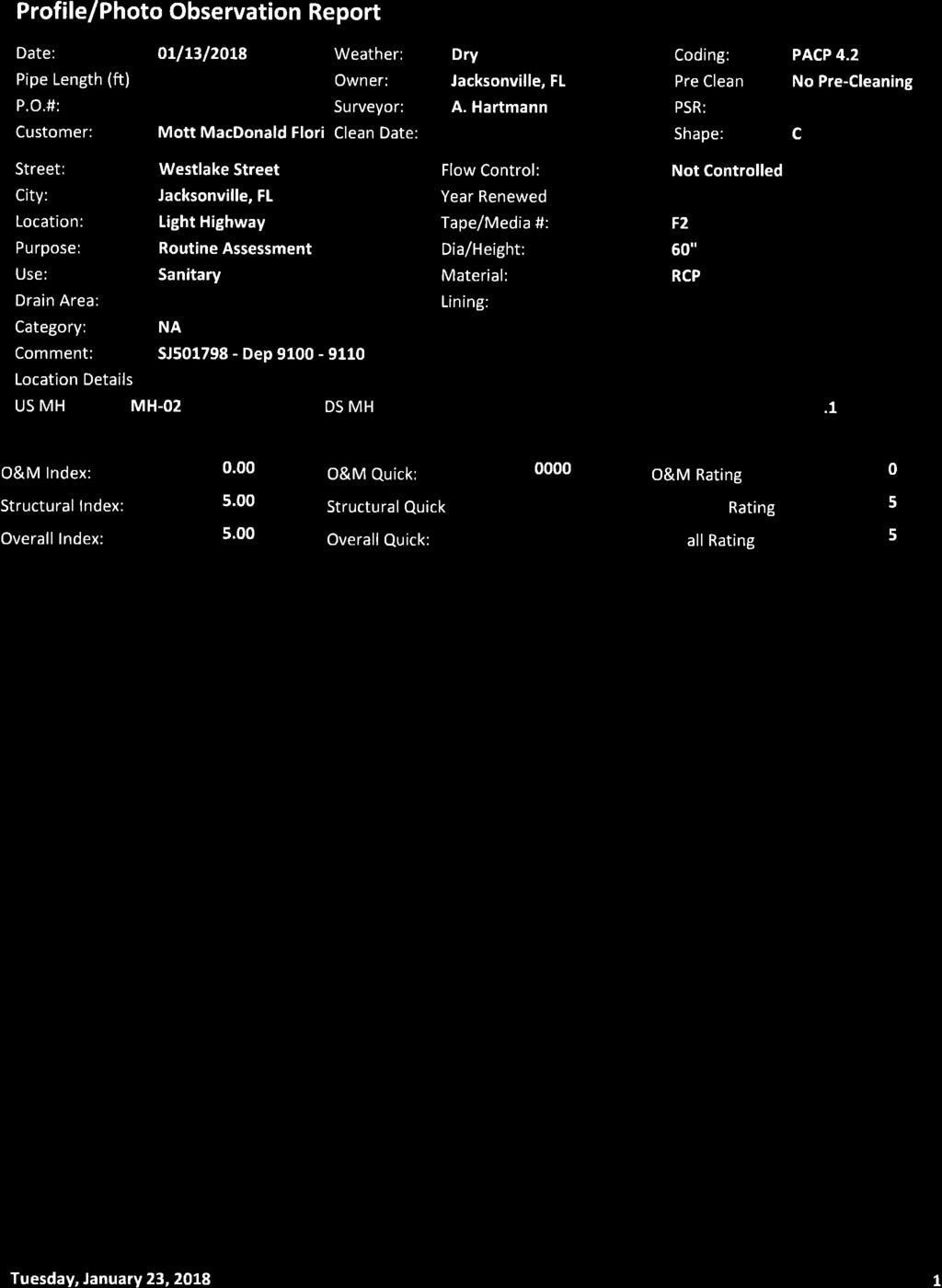
62
63
64
65
66
67
68
69
70
71
72
73

74
75
76
77
78
79
80
81
82
83
84
85
86
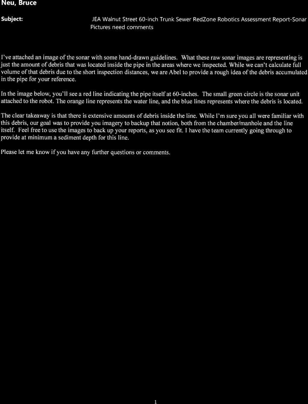

87

88


89

90
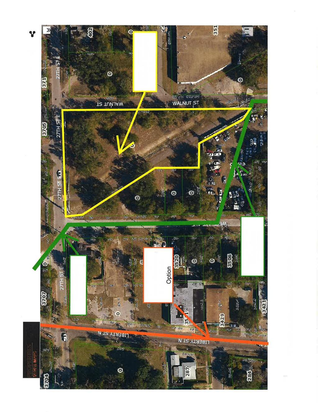
91

92

93

94


95
Memorandum. Dr. Wilbert Odem, Dr. Paul Trotta, and Mr. Justin Ramsey. From: Timothy Mahon, Patrick Belsheim, and Ali Alrayyes.
 Memorandum To: Dr. Wilbert Odem, Dr. Paul Trotta, and Mr. Justin Ramsey From: Timothy Mahon, Patrick Belsheim, and Ali Alrayyes Date: 10/17/2013 Re: Routes Decision Matrix Decision Matrix Methodology The
current supply and what is needed for future conditions; this is not the total water demand for these utilities.
 Southwest Missouri Water Delivery Systems, Hydraulic Analysis of Alternatives June 28, 2017 Page 2 current supply and what is needed for future conditions; this is not the total water demand for these
Specifications for Synchronized Sensor Pipe Condition Assessment (AS PROVIDED BY REDZONE ROBOTICS)
") Specifications for Synchronized Sensor Pipe Condition Assessment (AS PROVIDED BY REDZONE ROBOTICS) A. Scope of Work The work covered by these specifications consists of furnishing all materials, labor,
Specifications for Synchronized Sensor Pipe Condition Assessment (AS PROVIDED BY REDZONE ROBOTICS) A. Scope of Work The work covered by these specifications consists of furnishing all materials, labor,
TECHNICAL MEMORANDUM 002 EMORANNO. 001
 TECHNICAL MEMORANDUM 002 EMORANNO. 001 To: Jack Synder, P.E. EES Consulting From: Mort McMillen, P.E. Paul Larson, SE Date: October 13, 2010 Project: Cc: Taylor Bowen Subject: Technical Memorandum (TM)
East Downtown Tax Increment Reinvestment Zone (TIRZ) No. 15 Infrastructure Assessment Study
 No. 15 Infrastructure Assessment Study") East Downtown Tax Increment Reinvestment Zone (TIRZ) No. 15 Infrastructure Assessment Study Houston, TX Technical Memorandum April 15 th, 2009 Prepare by: 2950 North Loop West, Ste. 900 Houston, TX 77092
East Downtown Tax Increment Reinvestment Zone (TIRZ) No. 15 Infrastructure Assessment Study Houston, TX Technical Memorandum April 15 th, 2009 Prepare by: 2950 North Loop West, Ste. 900 Houston, TX 77092
SECTION 3 STREET DESIGN
 3.01 GENERAL SECTION 3 STREET DESIGN For purposes of geometric and structural design, streets shall be classified according to the following table. The City Engineer will determine the class of all proposed
Comments EXECUTIVE SUMMARY
 Comments 1. Under any Alternatives, MCDOT should provide better at-grade pedestrian crossing of Georgia Avenue and Forest Glen Road, including improved crosswalks with wider medians and adequate signal
DRAFT. A fifth objective, other considerations, has been added to capture considerations not captured by the four primary objectives.
 TECHNICAL MEMORANDUM Albany - Washington Avenue Traffic Calming Evaluation Matrix of Conceptual Alternatives Date: May 17, 2017 Project #: 17356 To: Aleida Andrino-Chavez From: Laurence Lewis, Sara Muse,
Asheville s Fairview Water System Improvements: from Modeling to Contract Documents. April 19, 2016 Meg Roberts, PE
 Asheville s Fairview Water System Improvements: from Modeling to Contract Documents April 19, 2016 Meg Roberts, PE City of Asheville Water Distribution System Customer elevations range 1,950 feet to 3,650
City of Margate, Florida. Neighborhood Traffic Management Manual
 City of Margate, Florida Neighborhood Traffic Management Manual Table of Contents Page No. I. INTRODUCTION... 1 II. TRAFFIC CALMING REQUEST AND PROCESSING PROCEDURES... 2 1. COMPLETE AND SUBMIT PROJECT
CLEANING, INSPECTION, AND TESTING OF SEWERS
 CLEANING, INSPECTION, AND TESTING OF SEWERS PART 1 - GENERAL 1.01 SECTION INCLUDES A. Cleaning, Inspecting, and Testing Sanitary Sewers B. Cleaning, Inspecting, and Testing Storm Sewers C. Cleaning and
SAWS QA/QC CHECKLIST WATER ADJUSTMENT/RELOCATION PROJECTS
 SAWS QA/QC CHECKLIST WATER ADJUSTMENT/RELOCATION PROJECTS Project Name: SAWS Water Job No.: CSJ No. (if applicable): Date: AWS Consultant: PROJECT INFORMATION N/A Yes No Joint Bid (COSA/TxDOT) N/A Yes
APPLYING VARIABLE SPEED PRESSURE LIMITING CONTROL DRIVER FIRE PUMPS. SEC Project No
 APPLYING VARIABLE SPEED PRESSURE LIMITING CONTROL DRIVER FIRE PUMPS SEC Project No. 1803007-000 November 20, 2006 TABLE OF CONTENTS I. ABSTRACT...1 II. INTRODUCTION...1 III. HISTORY...2 IV. VARIABLE SPEED
Consult with manufacturers concerning permeation of the pipe walls, jointing materials, valve seats, etc.
 Design Manual Chapter 4 - Water Mains 4C - Facility Design 4C-1 Facility Design A. General Water mains and appurtenances, including hydrants and valves, should be provided along all streets including connections
section 4 Existing Conditions, Issues, and Options
 section 4 Existing Conditions, Issues, and Options 4.0 Existing Conditions, Issues, and Options This section analyzes each segment of the corridor on a street to street basis. Each segment is discussed
DESIGN MEMORANDUM WITH DESIGN EXCEPTIONS SP SP
 DRAFT NOT FINAL (Note: document was not finalized due to an eastbound stopping site distance design issue that requires more detailed bridge and roadway design considerations. This discussion starts on
Paul Huston, P.E., Design-Build Coordinator Chuck Gonderinger, HDR Engineering. Minnesota Department of Transportation (the Department)
") To: From: Paul Huston, P.E., Design-Build Coordinator Chuck Gonderinger, HDR Engineering Date: March 20, 2001 Subject: Roadway Geometric Design Criteria Project: TH 14/218 Design-Build Project, SP 7408-29,
To: From: Paul Huston, P.E., Design-Build Coordinator Chuck Gonderinger, HDR Engineering Date: March 20, 2001 Subject: Roadway Geometric Design Criteria Project: TH 14/218 Design-Build Project, SP 7408-29,
City of Elizabeth City Neighborhood Traffic Calming Policy and Guidelines
 City of Elizabeth City Neighborhood Traffic Calming Policy and Guidelines I. Purpose: The City of Elizabeth City is committed to ensure the overall safety and livability of residential neighborhoods. One
2014 Street and Utility Improvement Project. Feasibility Report January 28, 2014
 2014 Street and Utility Improvement Project Feasibility Report January 28, 2014 Public Informational Meeting 22 residents from 17 properties signed in Questions about construction (FAQs) Eyebrow cul-de-sac
Technical Report Culvert A Hydraulic Analysis
 DATE: November 3, 2011 Technical Report Culvert A Hydraulic Analysis TO: FROM: RE: Jim Reiser, P.E. Project Manager Parsons Brinckerhoff, Inc. Kurt Killian, P.E., CFM Parsons Brinckerhoff, Inc. Design
This Chapter sets forth the minimum design, technical criteria and specifications to be used in the preparation of all roadway plans.
 4.1 GENERAL This Chapter sets forth the minimum design, technical criteria and specifications to be used in the preparation of all roadway plans. These Roadway Standards are for new construction and modification
Final Sidewalk Feasibility Study
 Garfield Drive From Anastasia Drive to Elizabeth Place City of South Daytona July 23, 2009 Final Sidewalk Feasibility Study Prepared for: Prepared by: Final Sidewalk Feasibility Study Garfield Drive 2
Building Great Neighbourhoods BELLEVUE AND VIRGINIA PARK
 Building Great Neighbourhoods BELLEVUE AND VIRGINIA PARK This is Meeting 2 Unfortunately, some residents in Bellevue and Virginia Park received the wrong information for this public open house (Meeting
RZC Appendix 8A Marymoor Subarea Street Requirements
 RZC Appendix 8A Marymoor Subarea Street Requirements For additional design details for Marymoor Subarea infrastructure, refer to the 2017 Marymoor Subarea Infrastructure Planning Report. STREET REQUIREMENTS
PORT ST. LUCIE UTILITY SYSTEMS DEPARTMENT FLUSHING REPORT
 FLUSHING REPORT Project Name: : of Record: Date of Inspection: Date Gallons Minutes Gallons Location of Test Per Minute Flushed Flushed Number of pigs used:. Total Gallons Flushed Number of pigs retreived:.
Roadway Design Manual
 Roadway Design Manual Manual Notice Archive by Texas Department of Transportation (512) 302-2453 all rights reserved Manual Notice 2009-1 From: Manual: Mark A. Marek, P.E Roadway Design Manual Effective
Owl Canyon Corridor Project Overview and Summary
 Owl Canyon Corridor Project Overview and Summary December 22, 2008 The Owl Canyon corridor (generally the connection between the I-25 / Larimer County Road 70 interchange and the US 287 / Larimer County
HENDERSON DEVELOPMENT 213, 217, 221, 221 ½, 223 HENDERSON AVENUE and 65 TEMPLETON STREET OTTAWA, ONTARIO TRANSPORTATION OVERVIEW.
 HENDERSON DEVELOPMENT 213, 217, 221, 221 ½, 223 HENDERSON AVENUE and 65 TEMPLETON STREET OTTAWA, ONTARIO TRANSPORTATION OVERVIEW Prepared for: 2294170 Ontario Inc. February 2, 2017 117-652 Report_1.doc
CITY OF ROSEVILLE DESIGN STANDARDS
 CITY OF ROSEVILLE DESIGN STANDARDS Section 1 Purpose and Definitions 1-1 Purpose PD 1 1-2 Design Practice PD 1 1-3 Definitions PD 1 Section 2 General Requirements 2-1 Plans by an Appropriate Engineer GR
Chapter 11. Culverts and Bridges Design Checklist for Culvert Design
 Yes No N/A Design Requirements I. GENERAL DESIGN GUIDELINES Chapter 11. Culverts and Bridges A. Culvert design is in accordance with the Culverts chapter of Volume 2 of the UDFCD Manual for additional
FORM A PASCO COUNTY ACCESS CONNECTION PERMIT APPLICATION
 FORM 901.3.A PASCO COUNTY ACCESS CONNECTION PERMIT APPLICATION The following information is required from all applicants directly or indirectly accessing any collector or arterial road or as otherwise
Legislative Update Williamsburg Residency
 Hampton Roads District Legislative Update Williamsburg Residency Jim Brewer, Resident Administrator 757-253-5140 Projects Under Way Warwick Boulevard Project http://www.warwickboulevard.org/ Contractors:
Business Plan Presentation
 2019 Department of Water Resources Business Plan Presentation Wednesday, August 29, 2018 Mission To Provide Superior Water Services at an Excellent Value Vision To be widely recognized as a leader in the
Magnolia Place. Traffic Impact Analysis. Prepared for: City of San Mateo. Prepared by: Hexagon Transportation Consultants, Inc.
 Magnolia Place Traffic Impact Analysis Prepared for: City of San Mateo Prepared by: Hexagon Transportation Consultants, Inc. Updated January 4, 2010 Table of Contents 1. Introduction...1 2. Existing Conditions...6
CIPP For Large-Diameter Pressure Pipes. Andrew Costa Aegion Corporation
 CIPP For Large-Diameter Pressure Pipes Andrew Costa Aegion Corporation WHAT TO EXPECT CIPP for Pressure Pipes Case Study Preliminary Condition Assessment Old Large Dia PCCP Force Main Factors for Rehabilitation
ADA TRANSITION PLAN 2013
 ADA TRANSITION PLAN 2013 TABLE OF CONTENTS Contents Introduction 1 Purpose 2 Identified Obstacles to the Public Right of Way 3 Criteria for Determining Impediments at Village Facilities 4 Removing Barriers
Planning & Zoning Commission
 Preliminary Plat Westwood, Section 3 Planning & Zoning Commission Planning & Development Department March 21, 2016 Request Subdivide approximately 38.1 acres of previously unplatted property to create
Building Great Neighbourhoods QUEEN ALEXANDRA
 Building Great Neighbourhoods QUEEN ALEXANDRA We are here today to Explain how the City is investing in improving your neighbourhood and how your neighbourhood will be improved to meet current City standards.
GENERAL LEGEND 12"CMP
 PLANS FOR X-REFS: west branch_ci FILE PATH: Z:\WEST BRANCH 36863 SIDEWALK IMPROVEMENTS 212 - SRTS - OLIPHANT\DRAWINGS\_PRODUCTION DRAWINGS\A.1 COVER PLOTTED: Monday, July 23, 212 2:44:13 PM OLIPHANT STREET
2010 STANDARD SPECIFICATIONS STANDARD DRAWINGS
 CITY OF REDMOND, OREGON 2010 STANDARD SPECIFICATIONS STANDARD DRAWINGS TABLE OF CONTENTS SECTION 1 TRENCHES TITLE 1-1 Utility Trench 1-2 Water Line & Sewer Line Separation 1-3 RR X-ING Single/Joint Use
Evaluating Surge Potential in CSO Tunnels
 14 Evaluating Surge Potential in CSO Tunnels Karen E. Ridgway Tunnels are being proposed to control combined sewer overflow (CSO) in numerous cities in the United States and Canada. The tunnels are intended
Street Paving and Sidewalk Policy
 City Commission Policy 600 Street Paving and Sidewalk Policy DEPARTMENT: Public Works DATE ADOPTED: June 7, 1995 DATE OF LAST REVISION: December 10, 2014 Policy No. 600.01 AUTHORITY: PASS City of Tallahassee-Leon
DRAFT. Table of Contents. Background
 Douglas County Table of Contents Existing Infrastructure 86 Funding 89 Policy and Program Recommendations 90 Infrastructure Recommendations 92 Conclusion 95 Background Home to 4,500 residents and Baker
LARIMER COUNTY: ENGINEERING DOUGLAS ROAD (CR 54)
") LARIMER COUNTY: ENGINEERING DOUGLAS ROAD (CR 54) INTRODUCTIONS * Pipeline 1041 Application Coordinator Todd Blomstrom Public Works Director Mark Peterson County Engineer Terry Gilbert Community Development
LARIMER COUNTY: ENGINEERING DOUGLAS ROAD (CR 54) INTRODUCTIONS * Pipeline 1041 Application Coordinator Todd Blomstrom Public Works Director Mark Peterson County Engineer Terry Gilbert Community Development
BPP / SUB
 Development Services Department Project/File: Lead Agency: Site address: Millwell Place Subdivision/ BPP15-0031/ SUB15-0064 This is a preliminary plat application to allow for the development of 68 building
TOWN OF CHAPEL HILL POLICY AND PROCEDURES FOR TRAFFIC CALMING MEASURES
 TOWN OF CHAPEL HILL POLICY AND PROCEDURES FOR TRAFFIC CALMING MEASURES (Adopted by the Town Council on June 30, 2004) (Revised December 6, 2010) (Revised February 8, 2016) POLICY AND PROCEDURES FOR TRAFFIC
Access requests to County streets and roadways are processed through one of the following methods:
 13.1 GENERAL APPLICATION PROCESS Access requests to County streets and roadways are processed through one of the following methods: A. Planned Developments may set general locations for access points.
ADOT Statewide Bicycle and Pedestrian Program Summary of Phase IV Activities APPENDIX B PEDESTRIAN DEMAND INDEX
 ADOT Statewide Bicycle and Pedestrian Program Summary of Activities APPENDIX B PEDESTRIAN DEMAND INDEX May 24, 2009 Pedestrian Demand Index for State Highway Facilities Revised: May 29, 2007 Introduction
AGENDA ITEM G-2 Public Works
 AGENDA ITEM G-2 Public Works STAFF REPORT City Council Meeting Date: 12/6/2016 Staff Report Number: 16-214-CC Regular Business: Approve the Oak Grove University Crane Bike Improvement Concept Plan, authorize
WHEREAS delivery trucks also pass through the Narrows, into the northern parking lot, to loading docks in the back of the building.
 CEDAR-ISLES-DEAN NEIGHBORHOOD ASSOCIATION ( CIDNA ) RESOLUTION OPPOSING A DRUG STORE DRIVE THRU, AND COMMENDING DORAN COMPANIES FOR PROPOSING MITIGATING AMENITIES INCLUDING NEW LANDSCAPING AND A DEDICATED
Americans with Disabilities Act Transition Plan for Public Right-of-Way Improvements
 Americans with Disabilities Act Transition Plan for Public Right-of-Way Improvements Prepared by: Public Works Department Engineering Division October 2015 Table of Contents Section I Introduction.. 3
CASTLE CREEK CORRIDOR PLANNING PUBLIC OPEN HOUSE
 CASTLE CREEK CORRIDOR PLANNING PUBLIC OPEN HOUSE Wednesday, November 15, 2017 AGENDA Project Background and Today s Goals Corridor Constraints and Conflicts Usage Information Public Process Schedule Review
PROJECT FACT SHEET May 25, 2018
 SITE CHALLENGES & PROJECT BACKGROUND In 2014, the City of Aspen identified the Castle Creek Bridge and Hallam Street corridor as a deficient link in Aspen s bicycle and pedestrian network. Safe and efficient
Building Great Neighbourhoods BONNIE DOON
 Building Great Neighbourhoods BONNIE DOON We Are Here Today To Explain the Neighbourhood Renewal Process Show you the Westwood Preliminary Design Ask for local knowledge Highlight the Local Improvement
ONONDAGA CREEKWALK PHASE II. Public Hearing Series 3
 ONONDAGA CREEKWALK PHASE II Public Hearing Series 3 Andrew Maxwell Director of Policy and Innovation, City of Syracuse Owen Kerney Assistant Director for City Planning Russell Houck, PE City of Syracuse
Introduction to Roadway Design
 Chapter Introduction to Roadway Design 1 This chapter lays the foundation for the Roadway Design course. You examine the roadway design workflow and the completed drawing files and review the project scope,
Welcome. Thank you for your interest in the Lewis & Clark Viaduct Concept Study
 Welcome Thank you for your interest in the Lewis & Clark Viaduct Concept Study Please use the arrows in the upper left hand corner to navigate through the presentation. Use the envelope icon to ask a question
What s New!!! Blackstone River Bikeway Fact Sheet: April 2004
 What s New!!! Blackstone River Bikeway Fact Sheet: April 2004 Construction / Design Update: * Worcester/Millbury, MA: One mile completed with another mile within the Rt. 20 contract currently under construction.
4. TRAIL DESIGN GUIDELINES
 Trail Design Guidelines 4. TRAIL DESIGN GUIDELINES This chapter provides specific design guidelines for the Humboldt Bay Trail that are consistent with the guidelines currently observed in California and
22. Specialty Valves.
 22. Specialty Valves. a. Types of Specialty Valves. 1) Use of the following specialty valves is covered in this section: Altitude Valve, Pressure Reducing Valve, Pressure Relief Valve, Swing Check Valve,
CHAPTER 8 STAKING SIGNALS AND LIGHTING FIELD GUIDE. 8.1 Staking Traffic Control Signal Systems
 CHAPTER 8 STAKING STAKING Correct staking of traffic control signal or lighting systems is critical to the appropriate placement of system components. 8.1 Traffic Control Signal Systems Locating the components
PROPOSED BICYCLE AND PEDESTRIAN FACILITY Vicinity of Route 123/I-495 Interchange Tysons, Fairfax County, Virginia
 PROPOSED BICYCLE AND PEDESTRIAN FACILITY Vicinity of Route 123/I-495 Interchange Tysons, Fairfax County, Virginia PRELIMINARY ENGINEERING REPORT Prepared for: Prepared by: July 2017 Table of Contents 1
Sponsored by the Office of Traffic and Safety of the Iowa Department of Transportation NOVEMBER 2001 CTRE
 PAVED SHOULDERS ON PRIMARY HIGHWAYS IN IOWA: AN ANALYSIS OF SHOULDER SURFACING CRITERIA, COSTS, AND BENEFITS EXECUTIVE SUMMARY Sponsored by the Office of Traffic and Safety of the Iowa Department of Transportation
Plan B Dam Breach Assessment
 Plan B Dam Breach Assessment Introduction In support of the Local Sponsor permit applications to the states of Minnesota and North Dakota, a dam breach analysis for the Plan B alignment of the Fargo-Moorhead
WYDOT DESIGN GUIDES. Guide for. Non-NHS State Highways
 WYDOT DESIGN GUIDES Guide for Non-NHS State Highways 2014 GUIDE FOR Non-NATIONAL HIGHWAY SYSTEM (Non-NHS) STATE HIGHWAYS PRESERVATION REHABILITATION RECONSTRUCTION INTRODUCTION This Guide is directed to
SUNRAY DRIVE/PERRINE RANCH ROAD FROM WEST OF DARLINGTON ROAD TO GRAND BOULEVARD AND PERRINE RANCH ROAD AT SEVEN SPRINGS BOULEVARD
 SUNRAY DRIVE/PERRINE RANCH ROAD FROM WEST OF DARLINGTON ROAD TO GRAND BOULEVARD AND PERRINE RANCH ROAD AT SEVEN SPRINGS BOULEVARD FINAL ROUTE AND POND STUDY PROJECT NO. C-9570.10 Prepared for: Pasco County
ROAD OCCUPANCY PERMIT APPLICATION # Damascus Township, 60 Conklin Hill Road, Damascus, PA Tel Fax
 Instructions: For a driveway access permit, fill in sections 1, 2, 3 and 4, and the appropriate drawings and sign. For a Utility access, fill in sections 1, 2, 3 and 5, and figures 1 and 3. Prepare a detailed
TRAFFIC STUDY GUIDELINES Clarksville Street Department
 TRAFFIC STUDY GUIDELINES Clarksville Street Department 9/1/2009 Introduction Traffic studies are used to help the city determine potential impacts to the operation of the surrounding roadway network. Two
WYDOT DESIGN GUIDES. Guide for. NHS Arterial (Non-Interstate)
") WYDOT DESIGN GUIDES Guide for NHS Arterial (Non-Interstate) 2014 GUIDE FOR NATIONAL HIGHWAY SYSTEM (NHS) HIGHWAYS (NHS ARTERIALS, Non-Interstate) PRESERVATION REHABILITATION RECONSTRUCTION INTRODUCTION
WYDOT DESIGN GUIDES Guide for NHS Arterial (Non-Interstate) 2014 GUIDE FOR NATIONAL HIGHWAY SYSTEM (NHS) HIGHWAYS (NHS ARTERIALS, Non-Interstate) PRESERVATION REHABILITATION RECONSTRUCTION INTRODUCTION
JONESBORO HIGHWAY 63 HIGHWAY 18 CONNECTOR STUDY
 JONESBORO HIGHWAY 63 HIGHWAY 18 CONNECTOR STUDY Craighead County May 2007 JONESBORO HIGHWAY 63 HIGHWAY 18 CONNECTOR STUDY Craighead County May 2007 Prepared by Planning and Research Division Arkansas State
DUNBOW ROAD FUNCTIONAL PLANNING
 DUNBOW ROAD FUNCTIONAL PLANNING Final Report August 3, 216 #31, 316 5th Avenue NE Calgary, AB T2A 6K4 Phone: 43.273.91 Fax: 43.273.344 wattconsultinggroup.com Dunbow Road Functional Planning Final Report
West Dimond Blvd Upgrade Jodhpur Street to Sand Lake Road
 West Dimond Blvd Jodhpur St to Sand Lake CSS Transportation Project Summary Municipality of Anchorage Project # 05 005 Project Manager: John Smith, P.E. (MOA PM&E) Project Administrator: Julie Makela,
VILLAGE OF NILES TRAFFIC CALMING POLICY
 INTRODUCTION There is increasing interest across the country in developing new strategies to reduce the speed and amount of traffic in residential neighborhoods. Measurement of speeds, traffic volumes,
CITY OF SOUTH DAYTONA
 CITY OF SOUTH DAYTONA FIVE YEAR WORK PLAN for HALF-CENT SALES TAX FY 2020-2025 Table of Contents Executive Summary Purpose of the Work Program... 3 Project List Magnolia Avenue North Roadway, Drainage
ADA Training Standard Plans
 ADA Training Standard Plans SCREEN READABLE VERSION IS IN THE MAKING AND WILL BE MADE AVAILABLE SOON 2018 MnDOT 2 Standard Plans 2017 Overview Overview PROWAG and Curb Ramp Basics Curb Ramp Types ADA Curb
ENHANCED PARKWAY STUDY: PHASE 2 CONTINUOUS FLOW INTERSECTIONS. Final Report
 Preparedby: ENHANCED PARKWAY STUDY: PHASE 2 CONTINUOUS FLOW INTERSECTIONS Final Report Prepared for Maricopa County Department of Transportation Prepared by TABLE OF CONTENTS Page EXECUTIVE SUMMARY ES-1
USING A LABYRINTH WEIR TO INCREASE HYDRAULIC CAPACITY. Dustin Mortensen, P.E. 1 Jake Eckersley, P.E. 1
 USING A LABYRINTH WEIR TO INCREASE HYDRAULIC CAPACITY Dustin Mortensen, P.E. 1 Jake Eckersley, P.E. 1 Plum Creek Floodwater Retarding Structure No. 6 is located in an area of Kyle, Texas, that is currently
SECTION 5: PEER CITY REVIEW
 SECTION 5: PEER CITY REVIEW 5.1 Introduction It is evident that the City of Lincoln continually strives to improve its operations and practices. To that end, a list of peer cities was developed to compare
City of Memphis On-Street Parking Modification Guidelines
 City of Memphis Effective Date: December 1, 2013 Bicycle/Pedestrian Program 125 N. Main Street Memphis, TN 38103 (901) 576-6710 www.bikepedmemphis.com City of Memphis Executive Summary It is current practice
La Crescent Township Zoning Ordinance
 La Crescent Township Zoning Ordinance Table of Contents SECTION 1 ~ PREAMBLE, TITLE, SHORT TITLE AND PURPOSE... 1 0101 Preamble... 1 0102 Title... 1 0103 Short Title... 1 0104 Purpose... 1 SECTION 2 ~
State Road 54/56 Tampa Bay s Northern Loop. The Managed Lane Solution Linking I-75 to the Suncoast Parkway
 State Road 54/56 Tampa Bay s Northern Loop The Managed Lane Solution Linking I-75 to the Suncoast Parkway SUNCOAST PARKWAY Both I 75 and the Suncoast Parkway are planning, or in the process of constructing,
PROJECT NO. 093 MA 199 H C. FEDERAL NO. xxxx WIKIEUP-WICKENBURG-PHOENIX HIGHWAY TEGNER STREET, ALTERNATIVE 10 PROJECT IMPROVEMENT
 PROJECT NO. 093 MA 199 H 5807 01C FEDERAL NO. xxxx WIKIEUP-WICKENBURG-PHOENI HIGHWAY TEGNER STREET, ALTERNATIVE 10 PROJECT IMPROVEMENT (INTERSECTION IMPROVEMENT) US 93/US 60 FINAL PROJECT ASSESSMENT April
ADA TRANSITION PLAN. For
 Page 1 of 7 ADA TRANSITION PLAN For PUBLIC WORKS DEPARTMENT 121 SW Port St. Lucie Boulevard Port St. Lucie, FL 34983 Phone: 772-871-5177 Website: www.cityofpsl.com September 2018 Table of Contents 1) Introduction
Driveway Design Criteria
 Design Manual Chapter 5 - Roadway Design 5L - Access Management 5L-4 Driveway Design Criteria A. General For efficient and safe operations, access drives and minor public street intersections can be improved
Carbondale to Murphysboro Bike Route JACKSON COUNTY
 Carbondale to Murphysboro Bike Route JACKSON COUNTY March, 2017 PREPARED BY: Southern Illinois Metropolitan Organization Table of Contents Introduction... 1 A. Project Purpose and Study Area... 1 B. Previous
Poor pavement condition Substandard Intersections. / Substandard bike/pedestrian/transit accommodations. Driveway access Environmental concerns
 Public Informational Meeting University Avenue (Allen Boulevard Segoe Road) March 23, 2011 City of Madison City of Middleton Village of Shorewood Hills Dane County Existing Roadway Conditions Poor pavement
Developed by: The American Traffic Safety Services Association (ATSSA) 15 Riverside Parkway, Suite 100 Fredericksburg, VA
 15 Riverside Parkway, Suite 100 Fredericksburg, VA") Addendum Developed by: The American Traffic Safety Services Association (ATSSA) 15 Riverside Parkway, Suite 100 Fredericksburg, VA 22406-1022 800-272-8772 This material is based upon work supported by
Addendum Developed by: The American Traffic Safety Services Association (ATSSA) 15 Riverside Parkway, Suite 100 Fredericksburg, VA 22406-1022 800-272-8772 This material is based upon work supported by
Building Great Neighbourhoods LANSDOWNE
 Building Great Neighbourhoods LANSDOWNE We are here today to Explain how the City is investing in improving your neighbourhood and how your neighbourhood will be improved to meet current City standards.
FINAL DESIGN TRAFFIC TECHNICAL MEMORANDUM
 FINAL DESIGN TRAFFIC TECHNICAL MEMORANDUM July 2014 FINAL (SR 43) Project Development and Environment Study From State Road 60 (Adamo Drive) to I-4 (SR 400) Hillsborough County, Florida Work Program Item
Complete Streets Process and Case Study: Taft / McMillian Two-Way Street Conversion Cincinnati, Ohio. Traffic Engineering Workshop June 4, 2014
 Complete Streets Process and Case Study: Taft / McMillian Two-Way Street Conversion Cincinnati, Ohio Traffic Engineering Workshop June 4, 2014 Complete Streets Streets that enable safe access for users
BRIDGE REPLACEMENT AND REHABILITATION PROGRAM
 BRIDGE REPLACEMENT AND REHABILITATION PROGRAM INTRODUCTION An integral element of the City's transportation infrastructure is a network of bridges designed to carry vehicular, railroad, light rail, pedestrian,
BASIC FREEWAY CAPACITY STUDIES Definitions
 Definitions A freeway is a divided highway facility having two or more lanes in each direction for the exclusive use of traffic with full control of access and egress. Freeway is the only facility that
TRAFFIC CALMING GUIDE FOR TORONTO CITY OF TORONTO TRANSPORTATION SERVICES DIVISION
 TRAFFIC CALMING GUIDE FOR TORONTO CITY OF TORONTO TRANSPORTATION SERVICES DIVISION CITY OF TORONTO TRANSPORTATION SERVICES DIVISION 2016 TRAFFIC CALMING GUIDE FOR TORONTO TABLE OF CONTENTS Introduction
Design Overview. Section 4 Standard Plans for Design. Pedestrian Access Routes. Pedestrian Access Routes. Overview. Cross Slope
 Design Overview Section 4 Standard Plans for Design Fall, 2017 Ann Johnson, PE Services Brady Rutman, SRF Consulting Group Overview Design Basics Recommendations: The Zone System Driveway Crossings Pedestrian
Roadway Classification Design Standards and Policies. Pueblo, Colorado November, 2004
 Roadway Classification Design Standards and Policies Pueblo, Colorado November, 2004 Table of Contents Page Chapter 1. General Provisions 1.1 Jurisdiction 3 1.2 Purpose and Intent 3 1.3 Modification 3
Traffic Impact Memorandum. May 22, 2018
 BISHOP PROFESSIONAL DEVELOPMENT BUILDING Proposed Land-use Change & Parking Modification 3601 SW 31st Street Topeka, Kansas 66614 CFS Project No. 185077 Traffic Impact Memorandum May 22, 2018 Prepared
City of Moorhead Committee of the Whole Meeting
 City of Moorhead Committee of the Whole Meeting Corridor Study Limits Center Avenue (Red River to 8th Street) TH 10 (Red River to TH 336) TH 75 (20th Ave S to Main Avenue) 2 Study Need: Project Overview
City of Wayzata Comprehensive Plan 2030 Transportation Chapter: Appendix A
 A1. Functional Classification Table A-1 illustrates the Metropolitan Council s detailed criteria established for the functional classification of roadways within the Twin Cities Metropolitan Area. Table
PROCEDURE FOR ACCOMMODATING PEDESTRIANS IN WORK ZONES FOR CONSTRUCTION AND MAINTENANCE
 PROCEDURE FOR ACCOMMODATING PEDESTRIANS IN WORK ZONES FOR CONSTRUCTION AND MAINTENANCE A.1 STANDARD Measures shall be taken to accommodate pedestrian traffic through and/or around Work Zones for Construction
County of Greenville South Carolina. Traffic Calming Program Neighborhood Traffic Education Program and Speed Hump Program
 County of Greenville South Carolina Traffic Calming Program Neighborhood Traffic Education Program and Speed Hump Program (rev) August 2008 I. PURPOSE The potential negative impacts from vehicular traffic