Math Review. Overview
|
|
|
- Donna Wade
- 5 years ago
- Views:
Transcription


1 Drawn by Steve Yan, CMD Math Review Shirley Ann Pinegar-Johnston MS RT(R)(T)CMD Overview Drawn by Steve Yan, CMD


2 Divergence & Intensity DIVERGENCE X-rays travel in Straight but Divergent lines INTENSITY Energy radiated per unit time per unit area

3 How do we calculate? Divergence Formula calculates the SIZE of the radiation field Inverse Square Formula helps us calculate the INTENSITY of a radiation beam Isocenter Point around which a gantry rotates Intersection of the collimator axis and the axis of rotation


4 If the field size is 10x15 at 100cm, what is it on a port film at 125cm? 100cm Image Receptor
5 Divergence If the field size is 10x15 at 100cm, what is it on a port film at 125cm? 100cm from the source 10 cm??? cm Field Size on portal film at 125cm Field width 1 = distance 1 10 = 100 Field width 2 distance 2 x 125 x = 12.5 Field length 1 = distance 1 15 = 100 Field length 2 distance 2 y 125 y = Magnification 100cm from the source 10 cm 12.5 cm Field Size on portal film at 125cm Comparing: Field Sizes 12.5/10 = 1.25 or Distances 125/100 = 1.25 Magnification Factor is 1.25
6 Field length 1 = distance 1 Field length 2 distance 2 40 = new SSD (56)(100) = (40)(new SSD) 140cm = new SSD
 + (20 x 6 ) 2 100 2 100 (4 x.06) + (10 x.06) Gap =.84cm.24 +.")
7 Divergence Gap Problem Gap = ( field size 1 xdepth ) + (field size 2 xdepth) 2 SSD 2 SSD What is the gap needed between two adjacent fields to a depth of 6cm. The field lengths of the fields are 8cm and 20cm, respectively at 100cm SSD? Gap = ( 8 x 6 ) + (20 x 6 ) (4 x.06) + (10 x.06) Gap =.84cm (Image from Stanton & Stinson p 242 Applied Physics for Radiation Oncology Revised Edition)


8 Feathering Initial Plan Used w permission TJU Graduate MD Student 2nd Plan - Feathered 1cm inferiorly 3rd Plan- Feathered additional 1 cm inferiorly


9 Used w permission TJU Graduate MD Student Feathering - CSI
10 Inverse Square Law states that the intensity is inversely proportional to the square of the distance from the source Inverse Square Formula Intensity 1 = (Distance 2 ) 2 Intensity 2 (Distance 1 ) 2 OR (Distance where Intensity is KNOWN) 2 x Intensity (Distance where Intensity is UNKNOWN) 2
11 Inverse Square Problem If the Intensity at 100cm is 200cGy, what is the Intensity at 50cm? 50cm??cGy 100cm 200cGy Inverse Square Problem If the Intensity at 100cm is 200cGy, what is the Intensity at 50cm? Intensity 1 = (Distance 2 ) 2 Intensity 2 (Distance 1 ) 2 200cGy = (50) 2 = Intensity at 50cm = 800cGy x (100) 2 (Distance where Intensity is KNOWN) 2 x Intensity (Distance where Intensity is UNKNOWN) 2 (100) 2 X 200cGy = Intensity at 50cm = 800cGy (50) 2
12 Drawn by Steve Yan, CMD Definitions Isocenter Point around which a gantry rotates Intersection of the collimator axis and the axis of rotation

13 SSD - SOURCE TO SKIN DISTANCE Source CENTRAL AXIS SSD 100cm SSD Field size is defined at SKIN surface SAD SOURCE TO AXIS DISTANCE SOURCE SAD 100cm CENTRAL AXIS SSD 92cm SSD + depth = SAD Field size is measured INSIDE the 92 + depth = 100 patient

14 Elapsed Days Elapsed Days Example Sun Mon Tues Wed Thur Fri Sat No Rx 180cGy 180cGy 180cGy 180cGy 180cGy No Rx No Rx 180cGy 180cGy 180cGy 180cGy 180cGy No Rx This chart shows 10 fractions at 180cGy per fraction over how many elapsed days?

15 Is the first treatment day considered Day 0 OR Day 1 Elapsed Days Example Sun Mon Tues Wed Thur Fri Sat No Rx 180cGy 180cGy 180cGy 180cGy 180cGy No Rx Day 0 Day 1 Day 2 Day 3 Day 4 Day 5 No Rx 180cGy 180cGy 180cGy 180cGy 180cGy No Rx Day 6 Day 7 Day 8 Day 9 Day 10 Day 11
16 Equivalent Square Find the equivalent square for a rectangular treatment field Sterling s Formula FS eq. 4 Area Perimeter 14 cm 10 cm Example 1 FS eq. 4 Area Perimeter L x W 2 (L + W) or sum of sides 10 x 14 = 140 = ( ) 48 4 x FS eq cm
 (2 2) (3 3) Perimeter 8 2 2 12 7 3 3 11 FS eq.")
17 10 cm 2 cm 14 cm 3 cm Example 2 Area FS eq. 4 Area Perimeter (10 14) (2 2) (3 3) Perimeter FS eq FS eq cm L x W 2 (L + W) or sum of sides


18 Can Swing Over Short Grenz Ray < KvP HVL in mm AL Contact Therapy KvP HVL mm AL Superficial Kvp Orthovoltage 1921 HVL in mm AL KvP HVL in mm Cu uses Thoreaus filter Tin, Copper, Aluminum from tube to patient Supervoltage Kvp Megavoltage 1961 > 1000 KvP HVL in mm Pb Image from Selman s The Basic Physics of Radiation Therapy 2 nd edition


19 Some D/Max Depths to Know Beam Energy Cobalt 60 4Mv 6Mv 10Mv 18Mv D/Max Depth.5cm 1.0cm 1.5cm 2.0cm 3.0cm Remember: D/max Depth is Primarily dependent on Beam Energy Effect of Energy on Isodose Curves **Normalized to D/Max Measured in Water Phantom** 60 Co 4Mv Build-Up Region Penumbra Image from Radiation Therapy Planning 2 nd Edition Gunilla C. Bentel 6Mv 15Mv

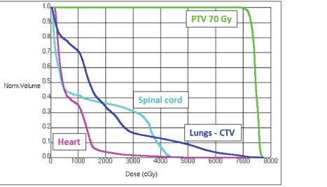
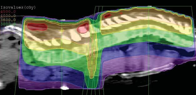
20 6Mv Beam From Bentel 2 nd edition p 101 Example of DVH DVH would be used to look at doses to normal structures/volume For example: Lung volume receiving JpGDmM3S6 2KLoii8K6bSE8MHheQ%3D&sa=X&ved=0ahUKEwjA54GC2KvbAhVG2lMKHcfPAYcQ9QEIPzAB#imgrc=RbzX6VoiRkuPPM:


 Stanton")
21 Beam Energy Whole Brain Equal dose from R/L Lateral 6Mv 15Mv Beam Weighting When the dose from EACH beam is the same, the beams are said to be Equally Weighted Different doses from EACH beam is called Unequally Weighted For example: AP:PA :: 2:1 dose ratio Anterior (120cGy) 2x + 1x = 180cGy 3x = 180cGy x = 60cGy Posterior (60cGy) Stanton & Stinson p261


22 3DCRT 3-Field Rectum Posterior Lateral Generally, a LOW Beam Energy was considered for the POSTERIOR Field HIGH Beam Energy was used on LATERAL Fields Monitor Units Calculations PDDs TARs/ TMRs Irregular Field

23 Percentage Depth Dose (PDD or %DD) Ratio of Dose at Depth compared to the dose at D/Max expressed as a percentage PDD at D/Max for ANY field Size, SSD, Beam Energy is 100% = 1.00 (decimal form)
24 PDD Table for 6Mv Factors Affecting PDD Field Size Beam Energy - Go deeper into patient - PDD Source to Skin Distance - (Mayneord s F Factor) **Mayneord s F Factor Calculation is no longer tested in the RTT Exam**
25 Percentage Depth Dose (PDD or %DD) Ratio of Dose at Depth compared to the dose at D/Max expressed as a percentage Mayneord s F Factor This is used when there is a change in the SSD from the chart. It is an application of the INVERSE SQUARE LAW!! F = (old SSD + depth) 2 X (new SSD + D/Max) 2 (old SSD + D/Max )2 (new SSD + depth) 2 F x old %DD value = %DD at new SSD
 2 X (new SSD + D/Max) 2 (old SSD +")
 = new PDD at 125cm SSD Monitor Unit (MU) Calculations Using PDD MU = Tumor Dose Reference Dose Rate x Sc")
26 Radiation Source Calculate the adjusted PDD value for a 60 Co machine using a treatment SSD of 110cm for a field size of 10x10 depth 5cm ****DO PROBLEM***** F = (old SSD + depth) 2 X (new SSD + D/Max) 2 (old SSD + D/Max )2 (new SSD + depth) 2 F x old PDD (.751) = new PDD at 125cm SSD Monitor Unit (MU) Calculations Using PDD MU = Tumor Dose Reference Dose Rate x Sc x Sp x PDD x (any other factors as needed) (at distance of Rx SSD + D/Max)
27 Monitor Unit Calculations Using PDD SOURCE SSD Field Size measured on SKIN Reference Dose Rate at SSD + D/max Reference Field Size generally 10x10 Scatter (Output) Factor This factor adjusts the machine output when the Treatment Field Size is different than 10x10 If the Field Size is greater than 10x10, the Output Factor will be GREATER than 1.0 (more scatter) If the Field Size is smaller than 10x10, the Output Factor will be Less than 1.0 (less scatter) The Output Factor can be subdivided into Collimator Scatter (Sc) and Phantom Scatter (Sp) Tumor Dose Reference Dose Rate x Sc x Sp x PDD x (any other factors as needed) (at distance of Rx SSD + D/Max)
28 Scatter Factor Tables 10x10 Reference Field Size Table from Washington & Leaver Monitor Unit Calculations Using PDD MU = Tumor Dose Reference Dose Rate x Sc x Sp x PDD x (any other factors as needed) (at distance of Rx SSD + D/Max)
 10x10 field size 6Mv Linear Accelerator 100cmSSD Reference Dose Rate at 101.5cm from source is 1.")
29 Monitor Units Calculation Using PDD Calculate the MU necessary to deliver: 200cGy to a depth of 3cm (PDD value = 95.1%) 10x10 field size 6Mv Linear Accelerator 100cmSSD Reference Dose Rate at 101.5cm from source is 1.0cGy/monitor unit Scatter Factor Tables 10x10 Reference Field Size Table from Washington & Leaver
 Rx SSD + D/max (100 + 1.")
30 PDD Table for 6Mv Monitor Units Calculation Using PDD 6Mv Linear Accelerator 200cGy = MU 1.0cGy/MU x 1.0 x 1.0 x.951 Reference Dose Rate at Sc Sp PDD (in decimal form) Rx SSD + D/max ( cm)
31 Dose to Another Point Along CAX Using PDD To calculate the dose at some point along the central axis use direct proportion. Dose at Point A = Dose at Point B %DD at Point A %DD at Point B Problem: For a 6Mv beam, what is the dose to the depth of 5cm when the dose at 3cm is 200cGy? PDD value at D3 =.951 PDD value at D5 =.876 Dose to Another Point Along CAX Using PDD Hint: Since 5cm depth is further AWAY from the source, the dose would be LESS than the dose at 3cm Source CENTRAL AXIS SSD 100cm D/max 200cGy at 3cm PDD =.951?? cgy at 5cm. PDD =.876
32 Dose to Another Point Along CAX Using PDD PDD value at D3 =.951 PDD value at D5 =.876 Dose at D3 = Dose at D5 PDD at D3 PDD at D5 200cGy = x dose at 5cm Depth x = cgy Dose to Another Point Along CAX Using PDD Problem: For a 6Mv beam, what is the dose to the D/Max when the dose at 3cm is 200cGy? PDD value at D3 =.951 Dose at D3 = Dose at D/Max PDD at D3 PDD at D/Max
33 Dose to Another Point Along CAX Using PDD Hint: Since 1.5cm depth (D/max depth for 6MV) is closer TOWARDS the source, the dose would be MORE than the dose at 3cm Source CENTRAL AXIS SSD 100cm D/max??? Dose at D/max... PDD = cGy at 3cm. PDD =.951 Dose to Another Point Along CAX Using PDD Problem: For a 6Mv beam, what is the dose to the D/Max when the dose at 3cm is 200cGy? PDD value at D3 =.951 Dose at D3 = Dose at D/Max PDD at D3 PDD at D/Max 200cGy = x dose at D/Max x = cgy


34 Dose to Another Point OFF CAX Using PDD Image and Text from Radiation Therapy Planning 2 nd Edition Gunilla C. Bentel
35 Tissue to Air Ratio (TAR) Developed by Johns to be used in Rotational Therapy Rotational Therapy has the gantry moving DURING the treatment while the beam is ON. A full treatment is called a Rotation Any treatment < is called an arc Tissue Air Ratio (TAR) ****TAR at D/Max is also called Back Scatter Factor****
36 Factors Affecting TAR Field Size Beam Energy - Go deeper into patient - ****Source to Skin Distance DOES NOT AFFECT TAR (~2% accuracy)**** 6Mv TAR
37 Monitor Unit Calculations Using TAR SOURCE SAD 100cm CENTRAL AXIS SSD 82cm **Machine Output AND Field Size measured at Treatment SAD** Monitor Units Calculation Using TAR 6Mv Linear Accelerator Calculate the MUs necessary to deliver 180cGy to a 5cm depth TAR at D5 = 95.2% 10x10 field size 100cmSAD 6Mv Linear Accelerator Machine output at 100cm from source is 1cGy/MU
38 Monitor Unit Calculation Using TAR MU = Tumor Dose Machine output x S c x TAR x (any other factors as needed) (at distance of Rx SAD) Monitor Units Calculation Using TAR 6Mv Linear Accelerator cGy/MU x 1.0 x.952 = MU machine output at Rx SAD S c TAR
39 PDD vs. TAR/TMR PDD was commonly used when SSD techniques were prevalent in radiotherapy. The use of 3DCRT and IMRT have required SAD treatment to become standard, and TAR/TMR is a more straightforward calculation system when using SAD treatment (SSD independent) As a rule on the exam, anytime a SSD treatment is mentions, use a PDD. For SAD treatments, use TAR or TMR Tissue Maximum Ratio Because of Measurement difficulties, the TMR was developed. The SAME factors which influence TAR, affect TMR in the same way
40 TAR compared to TMR Tissue to Air Tissue Air Ratio **************************************************************** epth of Interest Tissue Maximum Ratio Factors Affecting TMR Field Size Beam Energy - Go deeper into patient - ****Source to Skin Distance DOES NOT AFFECT TMR (~2% accuracy)****
41 Monitor Units Calculations Using TMR Calculate the MUs necessary to deliver 180cGy to a 5cm depth 10x10 field size 100cmSAD TMR = 97.7% 6Mv Linear Accelerator Machine output at 100cm from source is 1cGy/MU Monitor Units Calculation Using TMR MU = Tumor Dose Machine output x Sc x Sp x TMR x (any other factors as needed) (at distance of Rx SAD)
42 Monitor Units Calculation Using TMR 6Mv Linear Accelerator cGy/MU x 1.0 x 1.0 x.977 = MU machine output at Rx SAD Sc Sp TMR Gantry Speed for Rotational Treatments
43 Speed of Gantry for Rotational Treatment To set speed of gantry during a moving field treatment Treatment Monitor units number of degrees of treatment arc Problem for the Speed of the Gantry for Rotational Treatment What would be the monitor units per degree (aka speed of gantry) when The monitor units is 255 for an anterior arc of 180 degrees? Treatment Monitor units number of degrees of treatment arc 255/180 = = 1.42 MU/degree
44 Where is the FINISHING angle for the arc? If the MU are 255 and the MU/degree is 1.42 and the gantry starts at gantry angle of 270, travels clockwise WHERE is the FINISHING (aka STOP) gantry angle for this treatment? Where is the FINISHING angle for the arc? 1. Determine the number of degrees in the arc Treatment Monitor units number of degrees of treatment arc = gantry speed 255 = 1.42?????? = 180 degrees in the arc 2. Look at gantry angle orientation AND direction of the gantry movement

45 Where is the FINISHING angle for the arc? 0 START here AND.the FINISHING angle is.

 Bismuth, Lead, Tin & Cadmium Main Advantage Low Melting")
46 Blocking/MLC Kahn s 4 th Edition BLOCKS Shape the Radiation Field to shield/protect normal tissues Must be at least 5 HVL thick to allow < 5% transmission Made of Cerrobend (Lipowitz s metal) Bismuth, Lead, Tin & Cadmium Main Advantage Low Melting Point

47 Cerrobend Ratio to Lead Since cerrobend is a Lead alloy, we need MORE cerrobend to do the same shielding as Pure Lead ***1.25 cm Cerrobend ~ 1.00cm Pure Lead*** Problem: How much cerrobend is needed for blocks to be used on a machine whose HVL = 1.1cm Lead? 1.25 x 1.1= 1.375cm cerrobend x 5 = 6.875cm
48 Tray Factor Amount of Transmission through the plastic tray which holds the Cerrobend blocks Dose With Tray in place = 97cGy Dose Without Tray = 100cGy Transmission Factor = 97/100 =.97 (Same concept can be applied to compensator/physical wedges) Clarkson Calculation Also called Irregular Field Calculation corrects for the lack of scatter due to blocking The Tissue Air Ratio value needed to calculate the Monitor Unit, is made up of contributions from both the Primary radiation - 0x0 field size (TAR 0 ) when e- hits target, photons produced = primary beam added to scatter (SAR) TAR = TAR 0 + SAR

49 6Mv TAR TAR for 15x15 (open field) at 10cm depth =.844 TAR 0 for 0x0 at 10cm depth =.676 TAR = TAR 0 + SAR.844 = SAR = SAR.168 = SAR


50 Clarkson Calculation 1. Divide Field into Segments 2. Look up SAR value for EACH Radius Length 3. Get Average SAR value 4. Add Average SAR value to TAR 0 5. Use adjusted TAR value for MU Calculation Image from Bentel Radiation Therapy Planning 2 nd Edition p.94 Drawn by Steve Yan, CMD Wedges
 Dynamic Wedge The upper collimator moves DURING the")
51 Wedges The most FREQUENTLY used Beam Modifying Device The Physical wedges are shaped like a foot. Thick edge is called HEEL. Thin edge is called TOE (Image from Kahn The Physics of Radiation Therapy 4 th Edition p 182) Dynamic Wedge The upper collimator moves DURING the treatment giving a wedge effect

52 Wedge Angle Wedge Angle angle through which an isodose curve is tilted at the central ray of a beam at a specified depth. The range of wedge angles is generally degrees. wedge angle formula = 90 (.5 x hinge angle) Kahn wedge angle measurements recommended to be measured at 10cm depth 15 degree wedge 30 degree wedge 45 degree wedge 60 degree wedge
 Wedge Problems Determine the wedge angle to be used with a 150 0 hinge angle wedge angle formula = 90 (.5 x hinge angle) = 90 (.")
53 Hinge Angle Hinge Angle angle between the central rays of two fields optimum hinge angle = 180 (2 x wedge angle) (Image from Stanton & Stinson p242 Applied Physics for Radiation Oncology Revised Edition) Wedge Problems Determine the wedge angle to be used with a hinge angle wedge angle formula = 90 (.5 x hinge angle) = 90 (.5 x 150) = 90 (75) = 15 0 wedge angle Determine the optimum hinge angle to be used with 15 0 wedges optimum hinge angle = 180 (2 x wedge angle) = 180 (2 x 15) = 180 (30) = hinge angle

54 Wedge & Hinge Angles Table Wedge Angle Hinge Angle Wedge Factor Amount of Transmission through the physical wedge Dose With Wedge in place = 68cGy Dose Without Wedge = 100cGy Transmission Factor = 68/100 =.68 68% of beam TRANSMITTED through wedge 32% of radiation is attenuated

55 ALMOST Done. Electrons Electrons are generally used for boost treatments To determine the approximate depth of an electron isodose line to cover the deepest part of a tumor, the following rules of thumb can be used: Therapeutic Range Practical range Mev/4 ~ depth of 90% isodose line Mev/3 ~ depth of 80% isodose line Mev/2 ~ depth of 10% isodose line Khan 90% IDL Mev/3.2 80% IDL Mev/2.8
56 Electron Problem Determine the appropriate electron energy to treat a tumor at 4cm depth if the physician wants to treat to the 80% isodose line. (Image from Stanton & Stinson p242 Applied Physics for Radiation Oncology Revised Edition) Electron Problem 4cm to be covered by 80% IDL Available electron Energies: Rule of Thumb Mev/3 ~ depth of 80% isodose line 7Mev 10Mev 13Mev 16Mev 7Mev/3 = 2.33cm 10Mev/3 = 3.33cm 13Mev/3 = 4.33cm

57 Any Questions? Contact
58
Dosimetric Calculations. Lonny Trestrail
 Dosimetric Calculations Lonny Trestrail 20 October 2008 Objectives Dose Distribution Measurements PDD, OCR TAR, SAR, TPR, TMR, SPR, SMR Arc or Rotational Therapy Isodose Curves Point Dose Calculations
Review of fundamental photon dosimetry quantities
 Review of fundamental photon dosimetry quantities Narayan Sahoo Main sources of the materials included in this lecture notes are: (1) Radiation Oncology Physics: A Handbook for Teachers and Students Edited
Monitor Unit Calculations Part 2. Calculation of machine setting. Collimator setting
 Monitor Unit Calculations Part 2 George Starkschall, Ph.D. Department of Radiation Physics U.T. M.D. Anderson Cancer Center Calculation of machine setting reference dose machine setting =, reference dose
1. Question Answer cgy / MU cgy / MU 2. Question Answer
 GS020113: Introduction to Medical Physics III: Therapy s to home work problem set assigned on 3/22/11 1. Question A patient is set up at 100 cm SSD on a 6 MVX machine. The dose rate at 10 cm in phantom
Relative Dosimetry. Photons
 Relative Dosimetry Photons What you need to measure! Required Data (Photon) Central Axis Percent Depth Dose Tissue Maximum Ratio Scatter Maximum Ratio Output Factors S c & S cp! S p Beam profiles Wedge
Monitor Unit Calculations Part 1. Return to our first patient. Purpose. 62 yr old woman with Stage IIIB (T1N3M0) NSCLC rt lower lobe Dose prescription
 NSCLC rt lower lobe Dose prescription") Monitor Unit Calculations Part 1 George Starkschall, Ph.D. Department of Radiation Physics U.T. M.D. Anderson Cancer Center Return to our first patient 62 yr old woman with Stage IIIB (T1N3M0) NSCLC rt
Monitor Unit Calculations Part 1 George Starkschall, Ph.D. Department of Radiation Physics U.T. M.D. Anderson Cancer Center Return to our first patient 62 yr old woman with Stage IIIB (T1N3M0) NSCLC rt
The Royal Australian and New Zealand College of Radiologists. FRANZCR Examination Part I Radiation Oncology. Radiotherapeutic Physics.
 FRANZCR Examination Part I Radiation Oncology Radiotherapeutic Physics Candidate No.: The Royal Australian and New Zealand College of Radiologists FRANZCR Examination Part I Radiation Oncology Radiotherapeutic
Radiotherapy physics & Equipments
 Radiotherapy physics & Equipments RAD 481 Lecture s Title: Beam Modification devices in Radiotherapy Dr. Mohammed Emam Vision :IMC aspires to be a leader in applied medical sciences, health care education
Outline. Chapter 11 Treatment Planning Single Beams. Patient dose calculation. Patient dose calculation. Effect of the curved contour surface
 Chapter 11 reatment Planning Single Beams Radiation Dosimetry I Outline Basic terminology Curved contour surface correction (bolus, compensators, wedges) Oblique beam incidence Correction for tissue inhomogeneities
13 QUALITY ASSURANCE OF A LINEAR ACCELERATOR 13.1 COLLIMATOR ISOCENTER, JAWS, LIGHT FIELD VS INDICATORS, COLLIMATOR ANGLE INDICATORS.
 13 QUALITY ASSURANCE OF A LINEAR ACCELERATOR 13.1 COLLIMATOR ISOCENTER, JAWS, LIGHT FIELD VS INDICATORS, COLLIMATOR ANGLE INDICATORS. 13.1.1 TRAINING GOAL 13.1.1.1 Among the responsabilities of a medical
Field size and depth dependence of wedge factor for internal wedge of dual energy linear accelerator
 Journal of BUON 8: 55-59, 2003 2003 Zerbinis Medical Publications. Printed in Greece ORIGINAL ARTICLE Field size and depth dependence of wedge factor for internal wedge of dual energy linear accelerator
Commissioning an IMRT System for MLC Delivery. Gary A. Ezzell., Ph.D. Mayo Clinic Scottsdale
 Commissioning an IMRT System for MLC Delivery Gary A. Ezzell., Ph.D. Mayo Clinic Scottsdale Taking the broad view of commissioning Commissioning elements Validating the dosimetry system Commissioning the
Monitor Unit Verification for Small Fields
 Monitor Unit Verification for Small Fields Patrick Higgins, Ph.D University of Minnesota Department of Radiation Oncology October 10, 2013 The Issues: How do we verify the monitor units calculated by the
CHAPTER-2. Wedge filters are the most important beam modifiers used in
 CHAPTER-2 2. WEDGE FLTERS 2.1. NTRODUCTON Wedge filters are the most important beam modifiers used in radiotherapy which are placed in the path of photon beams to modify their isodose diistributions. The
3D Treatment Planning and verification with hand calculations
 3D Treatment Planning and verification with hand calculations Randy Holt, PhD, CEO Pacific Crest Medical Physics, Inc Chico, CA Dosimetric Calculations Calibration and Measurement Conditions Patient Conditions
CHAPTER 4 PRE TREATMENT PATIENT SPECIFIC QUALITY ASSURANCE OF RAPIDARC PLANS
 47 CHAPTER 4 PRE TREATMENT PATIENT SPECIFIC QUALITY ASSURANCE OF RAPIDARC PLANS 4.1 INTRODUCTION Advanced treatment techniques use optimized radiation beam intensities to conform dose distribution to the
OUTPUT at dmax in tissue 8x8 20x20 At 100cm SSD At 100cm SAD
 RAPHEX 2001 T1. All of the following are true regarding Percentage Depth Dose (PDD) except: A. Increases with increasing energy. B. Depends on field size. C. Is the dose at depth expressed as a % of the
JOURNAL OF APPLIED CLINICAL MEDICAL PHYSICS, VOLUME 3, NUMBER 4, FALL 2002
 JOURNAL OF APPLIED CLINICAL MEDICAL PHYSICS, VOLUME 3, NUMBER 4, FALL 2002 Comparison of monitor unit calculations performed with a 3D computerized planning system and independent hand calculations: Results
Treatment Planning Techniques for Larger Body Habitus Patients for Breast/Chestwall and Regional Lymph Nodal Irradiation
 Treatment Planning Techniques for Larger Body Habitus Patients for Breast/Chestwall and Regional Lymph Nodal Irradiation By Ruth Ann M. Good, CMD. R.T. (R)(T) Virginia Commonwealth University, Richmond,
Constancy checks of well-type ionization chambers with external-beam radiation units
 JOURNAL OF APPLIED CLINICAL MEDICAL PHYSICS, VOLUME 16, NUMBER 6, 2015 Constancy checks of well-type ionization chambers with external-beam radiation units Sara L. Hackett, 1a Benjamin Davis, 2 Andrew
Commissioning and quality assurance of a commercial intensity modulated radiotherapy (IMRT) treatment planning system PrecisePLAN
 treatment planning system PrecisePLAN") 22 Turkish Journal of Cancer Volume 37, No.1, 2007 Commissioning and quality assurance of a commercial intensity modulated radiotherapy (IMRT) treatment planning system PrecisePLAN SATISH PELAGADE 1, KALPANA
22 Turkish Journal of Cancer Volume 37, No.1, 2007 Commissioning and quality assurance of a commercial intensity modulated radiotherapy (IMRT) treatment planning system PrecisePLAN SATISH PELAGADE 1, KALPANA
Planning Assignment (3 field rectum)
") Megan Sullivan Clinical Lab Rectum April 25, 2016 Planning Assignment (3 field rectum) Use a CT dataset of the pelvis. Create a CTV by contouring the rectum (start at the anus and stop at the turn where
Megan Sullivan Clinical Lab Rectum April 25, 2016 Planning Assignment (3 field rectum) Use a CT dataset of the pelvis. Create a CTV by contouring the rectum (start at the anus and stop at the turn where
Clinical Implementation of Volumetric Modulated Arc Therapy
 Clinical Implementation of Volumetric Modulated Arc Therapy UT M.D. Anderson Cancer Center Ramaswamy Sadagopan, Rebecca M. Howell, Weiliang Du and Peter Balter Definition 2 Intensity Modulated Arc therapy
Zoubir Ouhib Lynn Cancer Institute
 Zoubir Ouhib Lynn Cancer Institute April 2015 Speaker for ELEKTA Brachytherapy using miniature X-ray sources Energy
TG-119 IMRT Commissioning Tests Instructions for Planning, Measurement, and Analysis Version 10/21/2009
 TG-119 IMRT Commissioning Tests Instructions for Planning, Measurement, and Analysis Version 10/21/2009 DISCLAIMER: This publication and associated spreadsheets and digital files are based on sources and
SnapShot IMRT with compensators and FFF beams
 SnapShot IMRT with compensators and FFF beams Vladimir Feygelman, PhD (1) Moffitt Cancer Center, Tampa, FL, USA Disclosure VF has a sponsored research agreement with.decimal. A short history of radiotherapy
CLINICAL IMPLEMENTATION OF RAPIDARC Treatment Planning Strategies to Improve Dose Distributions
 CLINICAL IMPLEMENTATION OF RAPIDARC Treatment Planning Strategies to Improve Dose Distributions Rebecca M. Howell, Ph.D., D.A.B.R, The University of Texas at M.D. Anderson Cancer Center Overview 2 Commissioning
WEDGE FILTERS FOR MEGAVOLTAGE ROENTGEN RAY BEAMS
 Acta Radiologica Oncology 23 (1984) Fusc. 6 FROM THE RADIATION THERAPY DEPARTMENT, ANTON1 VAN LEEUWENHOEK HOSPITAL, THE NETHERLANDS CANCER INSTITUTE, AMSTERDAM, THE PHILIPS MEDICAL SYSTEMS DIVISION, BEST,
Clinical Implementation of the TG-51 Protocol. David Followill Radiological Physics Center Houston Texas
 Clinical Implementation of the TG-51 Protocol David Followill Radiological Physics Center Houston Texas Current Implementation Status Current Implementation Status 1600 1400 TOTAL 1494 of 1623 ACTIVE INSTITUTIONS
ANALYSIS OF OFF-AXIS ENHANCDED DYNAMIC WEDGE DOSIMETRY USING A 2D DIODE ARRAY A CREATIVE PROJECT (3 SEMESTER HOURS) SUBMITTED TO THE GRADUATE SCHOOL
 SUBMITTED TO THE GRADUATE SCHOOL") ANALYSIS OF OFF-AXIS ENHANCDED DYNAMIC WEDGE DOSIMETRY USING A 2D DIODE ARRAY A CREATIVE PROJECT (3 SEMESTER HOURS) SUBMITTED TO THE GRADUATE SCHOOL FOR THE DEGREE MASTER OF ARTS BY CHARLES TRAVIS WEBB
ANALYSIS OF OFF-AXIS ENHANCDED DYNAMIC WEDGE DOSIMETRY USING A 2D DIODE ARRAY A CREATIVE PROJECT (3 SEMESTER HOURS) SUBMITTED TO THE GRADUATE SCHOOL FOR THE DEGREE MASTER OF ARTS BY CHARLES TRAVIS WEBB
Introduction. Materials and Methods
 STANDARD WEDGE AND TRAY TRANSMISSION VALUES FOR VARIAN, SEIMENS, ELEKTA/PHILIPS ACCELERATORS; A QUALITY ASSURANCE TOOL David S. Followill, Nadia Hernandez, and William F. Hanson Introduction The Radiological
Introduction. Introduction. The CyberKnife SRS/SBRT System. Introduction. Contour Structures. CyberKnife Components
 Introduction The CyberKnife SRS/SBRT System James M. Hevezi,, Ph.D., FACR CyberKnife Unit San Antonio, Texas CyberKnife Components Treatment Delivery (G3 Platform San Antonio) Robot (modified German auto
THE development of more advanced techniques in radiotherapy,
 1 A Geant4-based simulation of an accelerator s head used for Intensity Modulated Radiation Therapy F. Foppiano, B. Mascialino, M.G. Pia, M. Piergentili. Abstract We present a Geant4-based simulation,
Only 8% to go. TOTAL 1494 of 1623 ACTIVE INSTITUTIONS (92%) May-09. May-04 Nov-04. May-07. Nov-02 May-03. Nov-05. Nov-06. Nov-07 May-08.
 May-09. May-04 Nov-04. May-07. Nov-02 May-03. Nov-05. Nov-06. Nov-07 May-08.") Clinical Implementation of the TG-51 Protocol David Followill Radiological Physics Center Houston Texas 2009 AAPM Summer School Educational Objectives Improve your understanding of how to implement TG-51
Clinical Implementation of the TG-51 Protocol David Followill Radiological Physics Center Houston Texas 2009 AAPM Summer School Educational Objectives Improve your understanding of how to implement TG-51
1. BEAM MODIFIERS IN RADIOTHERAPY
 CHAPTER-1 1. BEAM MODIFIERS IN RADIOTHERAPY INTRODUCTION In radiotherapy, tumours under varying body contour are very often encountered. In such cases, due to the irregular body surface, the dose distribution
The dose distribution of medium energy electron boosts to the laryngectomy stoma
 JOURNAL OF APPLIED CLINICAL MEDICAL PHYSICS, VOLUME 2, NUMBER 1, WINTER 2001 The dose distribution of medium energy electron boosts to the laryngectomy stoma Ellen D. Yorke* Memorial Sloan-Kettering Cancer
A dose delivery verification method for conventional and intensitymodulated radiation therapy using measured field fluence distributions
 A dose delivery verification method for conventional and intensitymodulated radiation therapy using measured field fluence distributions Wendel Dean Renner a) Math Resolutions, LLC, 5975 Gales Lane, Columbia,
Scientific Journal of Nuclear Medicine & Radiation Therapy
 Scientific Journal of Nuclear Medicine & Radiation Therapy Research Article Radiotherapy Dose Calculation Program, for Monitoring and Commissioning Treatment Planning Systems - Ioannis Vamvakas*, Stella
Absorption measurements for a carbon fiber couch top and its modelling in a treatment planning system
 Absorption measurements for a carbon fiber couch top and its modelling in a treatment planning system G. Kunz, F. Hasenbalg, P. Pemler 1 1 Klinik für Radio-Onkologie und Nuklearmedizin, Stadtspital Triemli
High Speed Direct SAD Radiosurgery Beam Scanner
 Open Access Original Article DOI: 10.7759/cureus.20 High Speed Direct SAD Radiosurgery Beam Scanner Walter Nikesch 1, James M. Hevezi 2, Irene Monterroso 3, Daniel Navarro 4, James G. Schwade 5 1. CyberKnife
The Effect of Immobilisation Devices on Radiotherapy Dose Distributions. Alison Gray August 2007
 The Effect of Immobilisation Devices on Radiotherapy Dose Distributions A thesis submitted in fulfilment of the requirements for the Degree of Master of Applied Science (Medical and Health Physics) By
A simple theoretical verification of monitor unit calculation for intensity modulated beams using dynamic mini-multileaf collimation
 Radiotherapy and Oncology 71 (2004) 235 241 Technical Note A simple theoretical verification of monitor unit calculation for intensity modulated beams using dynamic mini-multileaf collimation Nadine Linthout*,
Commissioning of Elekta 6MV FFF Versa HD and Pinnacle
 Commissioning of Elekta 6MV FFF Versa HD and Pinnacle Poster No.: R-0044 Congress: Type: Authors: Keywords: DOI: 2014 CSM Scientific Exhibit L. Bendall, I. Patel, N. McGrath, C. Rowbottom; MANCHESTER/
A clinical comparison and analysis between conventional MLC based and solid compensator based IMRT treatment techniques
 The University of Toledo The University of Toledo Digital Repository Theses and Dissertations 2009 A clinical comparison and analysis between conventional MLC based and solid compensator based IMRT treatment
Investigation of Buildup Dose for Therapeutic Intensity Modulated Photon Beams in Radiation Therapy
 University of South Florida Scholar Commons Graduate Theses and Dissertations Graduate School 7-14-2010 Investigation of Buildup Dose for Therapeutic Intensity Modulated Photon Beams in Radiation Therapy
Treatment plan complexity metrics for predicting IMRT pretreatment. assurance results. Scott Crowe, QUT
 Treatment plan complexity metrics for predicting IMRT pretreatment quality assurance results Scott Crowe, QUT Pre-treatment QA Verification of fluence delivery to ensure that dose can be delivered accurately
A beam-matching concept for medical linear accelerators
 Acta Oncologica, 2009; 48: 192200 ORIGINAL ARTICLE A beam-matching concept for medical linear accelerators DAVID SJÖSTRÖM, ULF BJELKENGREN, WIVIANN OTTOSSON & CLAUS F. BEHRENS Copenhagen University Hospital,
Electronic Oncology Systems the Management and the Safety Measures. Hansen Chen, Director, TDSI
 Electronic Oncology Systems the Management and the Safety Measures Hansen Chen, Director, TDSI Radiation Oncology Department People Place Equipments Procedures Patients Hansen Chen 2 Radiation Oncology
Commissioning and periodic tests of the Esteya electronic brachytherapy system
 Review paper Educational Activity Commissioning and periodic tests of the Esteya electronic brachytherapy system Cristian Candela-Juan, PhD 1, Yury Niatsetski, MSc 2, Zoubir Ouhib, PhD 3, Facundo Ballester,
IMRT in clinical practice at the UMC-Utrecht. Utrecht
 3 IMRT in clinical practice at the UMC-Utrecht Utrecht Clinical use of IMRT Improvement of local control without increased incidence of normal tissue complications + Dose escalation in the prostate Step-and
Iranian Journal of Medical Physics
 Iranian Journal of Medical Physics ijmp.mums.ac.ir Verification of Monitor Unit Calculations for Eclipse Treatment Planning System by in-house Developed Spreadsheet Athiyaman Mayivaganan 1*, Hemalatha
TG219: IT'S USE, STRENGTHS AND WEAKNESSES
 1 CONFLICT OF INTEREST TG219: IT'S USE, STRENGTHS AND WEAKNESSES SOTIRI STATHAKIS, PHD, DABR None ROSTER STATEMENT OF THE PROBLEM Timothy C. Zhu, University of Pennsylvania, Philadelphia, PA (Co- Chair)
How to Design Medical Accelerator Systems for Reliability: IBA PT System
 How to Design Medical Accelerator Systems for Reliability: IBA PT System Yves Jongen Founder & Chief Research Officer Ion Beam Applications s.a. Belgium 1 Outline A short introduction of a proton therapy
TEST REPORT BEAMSCAN WITH HALCYON
 TEST REPORT BEAMSCAN WITH HALCYON UZ Leuven, November 20 th, 2017 + = Ideal BEAMSCAN tank dimensions to fit perfectly into the Halcyon bore Fast tank positioning using the Halcyon lasers, no electronics
Clinical Implementation of the IPEM 2003 Code of Practice for Electron Dosimetry
 Clinical Implementation of the IPEM 2003 Code of Practice for Electron Dosimetry Tom Jordan Royal Surrey County Hospital IPEM Electron Dosimetry Working Party: + DI Thwaites, AR DuSautoy, MR McEwen, AE
Ultrasound Dose Calculations
 Ultrasound Dose Calculations One of the advantages of ultrasound therapy remains the reasonably broad range of trials from which effective treatment doses can be established. In principle, there is no
7.65 ±0.05 mm of lead. The maximum energy of the bremsstrahlung photons was calibrated using the threshold for the D(-y,n)H reaction at
H reaction at") Am 7Roentgenolia6:ia6oia65, 1976 CENTRAL AXIS DEPTH DOSE FOR A 2.5 MV VAN DE GRAAFF GENERATOR DAVID W. ANDERSON, DAVID E. RAESIDE, REBA I. ADAMS, AND MYRON R. GOEDE 2 ABSTRACT: Central axis percentage
Am 7Roentgenolia6:ia6oia65, 1976 CENTRAL AXIS DEPTH DOSE FOR A 2.5 MV VAN DE GRAAFF GENERATOR DAVID W. ANDERSON, DAVID E. RAESIDE, REBA I. ADAMS, AND MYRON R. GOEDE 2 ABSTRACT: Central axis percentage
Commissioning of a new total body irradiation protocol
 University of Wollongong Research Online University of Wollongong Thesis Collection University of Wollongong Thesis Collections 2012 Commissioning of a new total body irradiation protocol Zoe Baldwin University
Comparison of ionization chambers of various volumes for IMRT absolute dose verification
 Comparison of ionization chambers of various volumes for IMRT absolute dose verification Leonid B. Leybovich, a) Anil Sethi, and Nesrin Dogan Department of Radiation Oncology, Loyola University Medical
COMPARISON BETWEEN PHYSICAL WEDGES AND VIRTUAL WEDGES IN LINAC
 COMPARISON BETWEEN PHYSICAL WEDGES AND VIRTUAL WEDGES IN LINAC by TAN ZI XIANG Thesis submitted in fulfillment of the requirements for the degree of Master of Science (Medical Physics) February 2015 ACKNOWLEDGEMENT
Validation of Treatment Planning Dose Calculations: Experience Working with Medical Physics Practice Guideline 5.a.
 International Journal of Medical Physics, Clinical Engineering and Radiation Oncology, 2017, 6, 57-72 http://www.scirp.org/journal/ijmpcero ISSN Online: 2168-5444 ISSN Print: 2168-5436 Validation of Treatment
GEANT4 SIMULATION OF AN ACCELERATOR HEAD FOR INTENSITY MODULATED RADIOTHERAPY
 The Monte Carlo Method: Versatility Unbounded in a Dynamic Computing World Chattanooga, Tennessee, April 17-21, 2005, on CD-ROM, American Nuclear Society, LaGrange Park, IL (2005) GEANT4 SIMULATION OF
The MC commissioning of CyberKnife with MLC (Tips and Tricks)
") The MC commissioning of CyberKnife with MLC (Tips and Tricks) Alain Guemnie Tafo, PhD UPMC Pinnacle, Harrisburg, PA Institute Gustave Roussy, Villejuif, France Disclaimer & Disclosure The views expressed
The MC commissioning of CyberKnife with MLC (Tips and Tricks) Alain Guemnie Tafo, PhD UPMC Pinnacle, Harrisburg, PA Institute Gustave Roussy, Villejuif, France Disclaimer & Disclosure The views expressed
USER MANUAL PROGRAM VERSION 1.0.1
 R WWW..COM REF 92730-92731 USER MANUAL PROGRAM VERSION 1.0.1 STANDARD IMAGING, INC. 7601 Murphy Drive Middleton, WI 53562-2532 Dec / 2004 2004 Standard Imaging, Inc. DOC #80464-01 TEL 800.261.4446 TEL
TG-61 deals with: This part of the refresher course: Phantoms. Chambers. Practical Implementation of TG-61:
 Practical Implementation of TG-61: II. Guidelines for clinical implementation of TG-61 J.P. Seuntjens Medical Physics Unit McGill University, Montreal General Hospital Montréal, Canada jseuntjens@medphys.mcgill.ca
AAPM s TG-51 protocol for clinical reference dosimetry of high-energy photon and electron beams
 AAPM s TG-51 protocol for clinical reference dosimetry of high-energy photon and electron beams Peter R. Almond Brown Cancer Center, Louisville, Kentucky 40202 Peter J. Biggs Department of Radiation Oncology,
Development of Graphical User Interfaces (GUI) software and database for radiation therapy applications
 software and database for radiation therapy applications") The University of Toledo The University of Toledo Digital Repository Theses and Dissertations 2005 Development of Graphical User Interfaces (GUI) software and database for radiation therapy applications
The University of Toledo The University of Toledo Digital Repository Theses and Dissertations 2005 Development of Graphical User Interfaces (GUI) software and database for radiation therapy applications
Practical Course in Reference Dosimetry, National Physical Laboratory February 2014 MV Photon Dosimetry in the Clinic Page 1 of 11
 MV Photon Dosimetry in the Clinic This document discusses both the scientific methods and the system of work required to calibrate a field instrument expanding upon the practical details of both.. Introduction
Surface buildup dose dependence on photon field delivery technique for IMRT
 Surface buildup dose dependence on photon field delivery technique for IMRT Shigeru Yokoyama, Peter L. Roberson, Dale W. Litzenberg, Jean M. Moran, and Benedick A. Fraass Department of Radiation Oncology,
Implementation of respiratory-gated VMAT on a Versa HD linear accelerator
 Received: 21 November 2016 Revised: 7 April 2017 Accepted: 5 June 2017 DOI: 10.1002/acm2.12160 RADIATION ONCOLOGY PHYSICS Implementation of respiratory-gated VMAT on a Versa HD linear accelerator Jeffrey
Basics of Proton Therapy. Proton Treatment Planning and Beam Optimization
 Basics of Proton Therapy Proton Treatment Planning and Beam Optimization SAM Educational Session, WE D BRB 2 Mark Pankuch, PhD Northwestern Medicine Chicago Proton Center Today s objectives Review the
FLUKA Simulations of Radiation Field in Second Accelerator Tunnel
 FLUKA Simulations of Radiation Field in Second Accelerator Tunnel Z.G. AMIRKHANYAN CANDLE Synchrotron Research Institute, Yerevan, Armenia E-mail: zamirkhanyan@asls.candle.am Content The purpose of this
3 1 PRESSURE. This is illustrated in Fig. 3 3.
 P = 3 psi 66 FLUID MECHANICS 150 pounds A feet = 50 in P = 6 psi P = s W 150 lbf n = = 50 in = 3 psi A feet FIGURE 3 1 The normal stress (or pressure ) on the feet of a chubby person is much greater than
Exradin Ion Chambers. What attributes make Exradin the smart choice? EXRADIN Ion Chambers
 EXRADIN Ion Chambers Exradin Ion Chambers Exradin (EXacting RADiation INstrumentation) Ion Chambers have been built for over 33 years, are recognized by top research institutes and standards laboratories,
Breast Treatment System REFERENCE MANUAL
 Breast Treatment System REFERENCE MANUAL This manual may not be reproduced in whole or in part, by mimeograph or any other means, without the written permission of Diacor, Inc. The MammoRx Breast Treatment
Arithmetic with Units of Measure
 Arithmetic with Units of Measure Reteaching 81 Math Course 1, Lesson 81 If units are not the same, convert first. Example: 2 ft + 12 in. 24 in. + 12 in. or 2 ft + 1 ft To add or subtract measures, keep
RADIOLOGY/ FLUOROSCOPY 15 RAD-CHECK PLUS X-RAY EXPOSURE METER
 RADIOLOGY/ FLUOROSCOPY 15 RAD-CHECK PLUS X-RAY EXPOSURE METER Proven Rad-Check technology specifically designed to provide you with the ultimate in versatility and cost-effective operation. Fast and easy
TG-51: Experience from 150 institutions, common errors, and helpful hints
 TG-51: Experience from 150 institutions, common errors, and helpful hints Ramesh C. Tailor, Ph. D., William F. Hanson, Ph.D., and Geoffrey S. Ibbott, Ph.D. Department of Radiation Physics, University of
Radiation Producing Machines Radiation Safety Training for X-ray Diffraction Units
 INTRODUCTION Radiation Producing Machines Radiation Safety Training for X-ray Diffraction Units RADIATION SAFETY GUIDE IMAGING AND MICROSCOPY FACILITY University of California, Merced Training Document
Experimental verification of a Monte Carlo-based MLC simulation model for IMRT dose calculations in heterogeneous media
 Experimental verification of a Monte Carlo-based MLC simulation model for IMRT dose calculations in heterogeneous media N Tyagi 1, B H Curran, P L Roberson, J M Moran, E Acosta and B A Fraass Department
VariSource High Dose Rate Afterloader Procedures. For Performing Breast Brachytherapy with. The SAVI TM Applicator
 VariSource High Dose Rate Afterloader Procedures For Performing Breast Brachytherapy with The SAVI TM Applicator Contents I. CT Evaluation (~1 week prior to insertion) II. SAVI Applicator Implantation
Problem 1. A cuboid of length x, width 5 less than x and a height of half the length has a surface area of 250 cm 2. Show that 4x 2 15x 250 = 0
 Problem 1 Expand x(x+5) Write an expression for: 6 less than x Calculate the surface area of the cuboid Simplify 5x + x 2 + 8x + 3 + x 2 half of x 5 cm 8 cm 3 cm A cuboid of length x, width 5 less than
Abstract: Introduction:
 Are photon and electron beam calibrations more consistent with TG-51 than with TG-21? Ramesh C. Tailor, William F. Hanson, Nathan Wells, and Geoffrey S. Ibbott. U.T. MD Anderson Cancer Center, Houston
Larry A. DeWerd, Ph.D., FAAPM UW ADCL & Dept. of Medical Physics University of Wisconsin
 Larry A. DeWerd, Ph.D., FAAPM UW ADCL & Dept. of Medical Physics University of Wisconsin NCCAAPM Meeting Oct 11,2013 Larry DeWerd has a partial interest in Standard Imaging Talks from people who have been
Walk - Run Activity --An S and P Wave Travel Time Simulation ( S minus P Earthquake Location Method)
") Walk - Run Activity --An S and P Wave Travel Time Simulation ( S minus P Earthquake Location Method) L. W. Braile and S. J. Braile (June, 2000) braile@purdue.edu http://web.ics.purdue.edu/~braile Walk
Walk - Run Activity --An S and P Wave Travel Time Simulation ( S minus P Earthquake Location Method) L. W. Braile and S. J. Braile (June, 2000) braile@purdue.edu http://web.ics.purdue.edu/~braile Walk
Exposure System Selection
 Principles of Imaging Science II (RAD120) Exposure Systems Exposure System Selection Radiographic exposure is a very complex process Best technique systems manipulate one variable while holding others
Firestop Products and Systems Estimating Guide
 F i rr eessttooppppi ni ng g http://flamesafe.rectorseal.com PRODUCT DATA UPDATES TECH LETTERS DETAILS MSDS CONTACTS FAQS Firestop Products and Systems Estimating Guide Through-penetrations Estimating
INTRODUCTION TABLE OF CONTENTS
 2 INTRODUCTION Thank you for choosing Servometer to design and manufacture your unique, new electrodeposited bellows for your particular application. The definitions, formulas and design parameters inside
MIT Analytical X-Ray Safety Policies and Procedures
 5th Edition 2014 MIT Analytical X-Ray Safety Issued by: MIT Radiation Protection Committee Contents 1.0 Program Overview...1 2.0 Purpose...1 3.0 Scope and Application...2 4.0 Radiation Protection Program
Perimeter. Perimeter is the distance around a figure. Add to find the perimeter (P) of each figure. P
 of each figure. P") Place Value: Large Numbers... 5 Comparing Numbers...6 Rounding Numbers...7 Two-Digit Addition with Regrouping...8 Three-Digit Addition with Regrouping...9 Addition of Large Numbers... 10 Problem olving:
Place Value: Large Numbers... 5 Comparing Numbers...6 Rounding Numbers...7 Two-Digit Addition with Regrouping...8 Three-Digit Addition with Regrouping...9 Addition of Large Numbers... 10 Problem olving:
Disclosures. What Is So Hard? End of ITV: Gating is the Best ITV Killer 8/3/2016. Daniel A. Low, Ph.D. UCLA. Varian Grant Siemens Grant Accuray Grant
 Real Timefullness 8/3/2016 End of ITV: Gating is the Best ITV Killer Daniel A. Low, Ph.D. UCLA Varian Grant Siemens Grant Accuray Grant Disclosures What Is So Hard? Light Ultrasound MRI X Ray Planar X
COMPASS. Dr. Lutz Müller. AK IMRT Bamberg April D IMRT Verification in Patient Anatomy
 COMPASS 3D IMRT Verification in Patient Anatomy AK IMRT Bamberg April 2010 Dr. Lutz Müller Patient-specific Verification? CT Treatment unit Gantry =0 Treatmt unit Patient couch X-ray beam Patient couch
Dynamic wedges dosimetry and quality control
 Original Paper Received: 2005.06.07 Accepted: 2006.02.28 Published: 2006.04.28 Authors Contribution: A Study Design B Data Collection C Statistical Analysis D Data Interpretation E Manuscript Preparation
39 WAYS TO USE CUISENAIRE RODS VISIT OUR NEW WEBSITE
 39 WAYS TO USE CUISENAIRE RODS VISIT OUR NEW WEBSITE WWW.KCS4EDUCATION.CO.UK FREE NEXT DAY DELIVERY BEST VALUE FOR MONEY DEDICATED CUSTOMER SERVICE Your trusted partner CALL: 0808 281 9440 ONLINE: www.kcs4education.co.uk
Density and Archimedes Principle 11-cor
 Density and Archimedes Principle 11-cor Objectives: To understand the concept of density and its relationship to various materials. To understand and use Archimedes Principle. Equipment: Dial calipers,
Physics and Quality Assurance
 Disclosure Physics and Quality Assurance Consultancy agreements with Nucletron, Hologic Mahta M. McKee, MS, DABR Department of Radiation Oncology Wake Forest University Health Sciences Agenda Current Treatment
Beam modeling and VMAT performance with the Agility 160-leaf multileaf collimator
 JOURNAL OF APPLIED CLINICAL MEDICAL PHYSICS, VOLUME 14, NUMBER 2, 2013 Beam modeling and VMAT performance with the Agility 160-leaf multileaf collimator James L. Bedford, a Michael D. R. Thomas and Gregory
ON THE RELATIVE ADEQUACY OF SOME AMERICAN CHAMBERS FOR MEASUREMENTS IN THE GRENZ RAY RANGE*
 ON THE RELATIVE ADEQUACY OF SOME AMERICAN CHAMBERS FOR MEASUREMENTS IN THE GRENZ RAY RANGE* VICTOR H. WITTEN, M.D., EDGAR N. GRISEWOOD, M.A. AND ELEANOR OSHRY, B.S.t The use of grenz radiation has been
OPERATION. Estimated kerf width compensation. HPR260 Manual Gas Instruction Manual 4-9
 Estimated kerf width compensation The widths in the chart below are for reference. Differences between installations and material composition may cause the specific user results to vary from those shown
LAB 7. ROTATION. 7.1 Problem. 7.2 Equipment. 7.3 Activities
 LAB 7. ROTATION 7.1 Problem How are quantities of rotational motion defined? What sort of influence changes an object s rotation? How do the quantities of rotational motion operate? 7.2 Equipment plumb